TGF60G - Stove Tisira - Free user manual and instructions
Find the device manual for free TGF60G Tisira in PDF.

User questions about TGF60G Tisira
0 question about this device. Answer the ones you know or ask your own.
Ask a new question about this device
Download the instructions for your Stove in PDF format for free! Find your manual TGF60G - Tisira and take your electronic device back in hand. On this page are published all the documents necessary for the use of your device. TGF60G by Tisira.
USER MANUAL TGF60G Tisira
IMPORTANT // Please ensure that you read through this user manual prior to installation and use. This manual contains important information to ensure optimal performance and keep you safe. Please retain your proof of purchase, as this will be required in the event that you require warranty service. Remember to retain this manual for future reference.
t tisira

text_image
www.tisira.comHELLO
CONGRATULATIONS ON THE SELECTION OF THIS TISIRA APPLIANCE. TISIRA APPLIANCES HAVE BEEN SPECIFICALLY DESIGNED FOR AUSTRALIAN AND NEW ZEALAND KITCHENS.
Please read through this user manual carefully as it contains information that will ensure that your appliance is installed correctly, important operating & care instructions and also some advice of what you need to do if this appliance is not performing as intended.
CONTENTS
HELLO 2
CONTENTS 3
WARNING & SAFETY INFORMATION 4
PRODUCT OVERVIEW 5
OPERATING INSTRUCTIONS 6-7
MAINTAINING YOUR COOKTOP 8
INSTALLATION 9-14
PRODUCT SPECIFICATIONS 15
WARRANTY TERMS & CONDITIONS 16
PROOF OF PURCHASE 17
NOTES 18-19
CONTACT DETAILS 20
WARNING & SAFETY INFORMATION
- DO NOT USE OR STORE FLAMMABLE MATERIALS IN THE APPLIANCE STORAGE DRAWER OR NEAR THIS APPLIANCE
• DO NOT SPRAY AEROSOLS IN THE VICINITY OF THIS APPLIANCE WHILE IT IS IN OPERATION
• DO NOT MODIFY THIS APPLIANCE - This appliance is not intended for use by persons (including children) with reduced physical, sensory or mental capabilities, or lack of experience and knowledge, unless they have been given supervision or instruction concerning use of the appliance by a person responsible for their safety.
- Young children should be supervised to ensure that they do not play with the appliance.
- There shall be adequate ventilation of the room when the rangehood is used at the same time as appliances burning gas or other fuels.
- You must read the details concerning the method and frequency of cleaning.
- If the supply cord of this equipment is damaged, it must only be replaced by the manufacturer or its service agent or a similarly qualified person in order to avoid a hazard.
- This appliance has been designed for indoor domestic use only.
- Where this appliance is installed in a marine craft or in caravans, it shall not be used as a space heater.
- Keep packaging out of reach of children at all times. To avoid burns, young children should be kept away.

Do not place anything, e.g. flame tamer, asbestos mat, between pan and pan support as serious damage to the appliance may result.

Do not remove the pan support and enclose the burner with a wok stand as this will concentrate and deflect heat onto the hotplate.

Do not use large pots or heavy weights which can bend the pan support or deflect flame onto the hotplate.
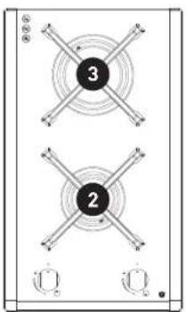
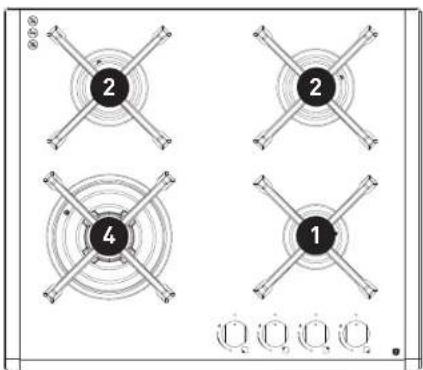
PRODUCT OVERVIEW
text_image
3 2TGF30G

natural_image
Technical diagram of a mechanical or electrical component with two circular components labeled 2 and 4, and mounting holes (no text or symbols beyond labels)TGWF30G

text_image
2 2 3 1TGF60G
text_image
2 2 4 1TGWF60G
text_image
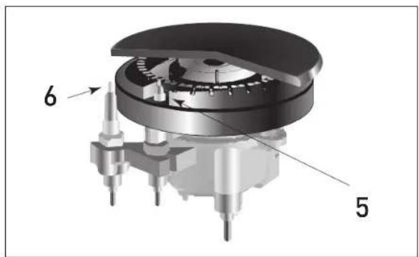
6 5COMPONENT IDENTIFICATION
- Auxiliary Gas Burners
- Semi-rapid burner
- Rapid burner
- Triple ring burner
- Igniter for Gas Burners (only on certain models)
- Safety Device - Flame Failure (only on certain models) activates if the flame accidentally goes out (spills, drafts, etc.), interrupting the delivery of gas to the burner.

text_image
2 3 4 1 2TGWF90G

tisira
www.tisira.com
OPERATING INSTRUCTIONS
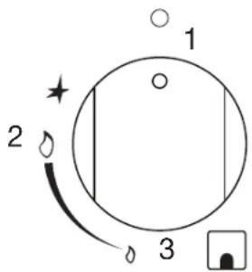
The position of the corresponding gas burner is indicated on each control knob.
GAS BURNERS
The burners differ in size and power. Choose the most appropriate one for the diameter of the cookware being used. The burner can be regulated with the corresponding control knob by using one of tile following settings:
text_image
1 2 3-
Off
-
High
-
Low
To light a burner, simply press the corresponding knob all the way in and, then, turn it in the counter-clockwise direction to the High setting, keeping it pressed in until the burner lights.
CAUTION // If the burner accidentally goes out, turn off the gas with the control knob and try to light it again after waiting at least 1 minute.
To turn off a burner // turn the knob in the clockwise direction until it stops (it should be on the "off" setting).
OPERATING INSTRUCTIONS
USE THE CORRECT COOKWARE
| BURNER ∅ COOKWARE DIAMETER (CM) | |
| RAPID 20-28 | |
| SEMI RAPID 14-20 | |
| AUXILIARY 8-14 | |
| TRIPLE RING WOK ABOVE 26 | |
- Cookware should be centralised on the burner when in use.
- Do not use round bottomed pans (e.g woks) without appropriate wok support recommended by the manufacturer.
- Adjust the flame according to the size of your cookware, not allowing the flame to extend past the edge of the pan.

natural_image
Four line drawings of cooking pots with crossed x marks, no text or symbols presentMAINTAINING YOUR COOKTOP
GENERAL MAINTENANCE
Before cleaning or performing maintenance on your appliance, disconnect it from the electrical power supply.
To extend the life of the cooktop, it is important that it be cleaned carefully and thoroughly on a frequent basis, keeping in mind the following:
- The enameled, cast iron and stainless steel parts must be washed with warm water without using abrasive powders/cloths or corrosive substances which could ruin them.
- The removable parts of the burners should be washed frequently with warm water and soap, making sure to remove caked-on substances. After cleaning, the burners and diffusers must be well dried.
- On cooktops with automatic ignition, the end of the electronic ignition device must be cleaned carefully and frequently, making sure that the gas holes are not clogged.
SERVICING INSTRUCTIONS
Always refer servicing to an authorised service person. It is recommended that the appliance be serviced at least once per year to ensure the appliance continues to operate correctly and safely.
GREASING THE GAS VALVES
Over time, the gas valves may stick or become difficult to turn. If this is the case, they must be cleaned on the inside and then re greased.
NOTICE // This procedure must be performed by an authorised service person.
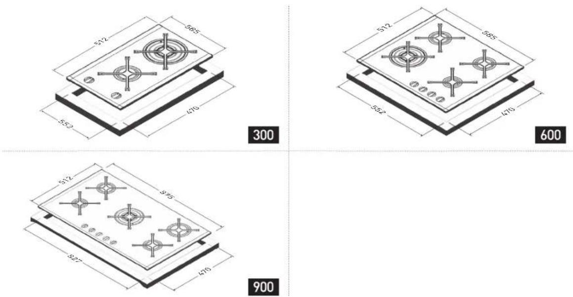
INSTALLATION
text_image
512 565 470 552 300 512 585 470 532 600 512 545 470 900The following instructions are directed at the qualified installer so that the installation and maintenance procedures may be followed in the most professional and expert manner possible.
Gas inlet is located at the rear right hand side 50mm from the rear edge. Electrical terminal is located at the rear, 60mm from the left edge on the 300 models, at the rear centre for the 600 models and at the rear, 300mm from the left edge on the 700 and 900 models.
Fixing brackets are provided which allow the hob to be installed in 30-40mm benchtops. It is recommended to use all supplied brackets to ensure that the hob is secularly installed.
The unit is also supplied with a seal with adhesive on one side.
- Remove trivets, burner caps and diffusers.
- Turn the cooktop over and rest the glass side on a cloth
- Apply the self-adhesive seal "G" as illustrated to the right
- Slot the cooktop into the cutout and position
- Position the cooktop in the recess and secure with the brackets as shown to the right

text_image
G Adhesive Side G 30mm 40mm 30mm minINSTALLATION
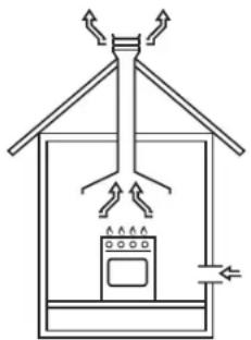
IMPORTANT // This unit may be installed and used only in permanently ventilated rooms in accordance with AS5601 (gas installations), local authority and any other statutory regulations. The following requirements must be observed:
A The room must be fitted with a ventilation system which vents smoke and gases from combustion to the outside. This must be done by means of a hood or electric ventilator that turns on automatically each time the hood is operated.
natural_image
Simple line drawing of a roof-mounted air conditioner unit with fan blades and control panel (no text or symbols)In a chimney stack or branched flue. (Exclusively for cooking appliances)
natural_image
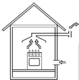
Simple line drawing of a house with air flow arrows and appliances (no text or symbols)Directly to the outside
B The room must also allow for the influx of the air needed for proper combustion. The flow of air for combustion purposes must, not be less than 2m^3/h per kW of installed capacity. The supply of said air can be affected by means of direct influx from the outside through a duct with a inner cross section of at least 100cm^2 which must not be able to be accidentally blocked. Those appliances which are not fitted with a safety device to prevent the flame from accidentally going out must have a ventilation opening twice the size otherwise required, i.e. a minimum of 200 cm^2 (Fig. A). Otherwise, the room can be vented indirectly through adjacent rooms fitted with ventilation ducts to the outside as described above, as long as the adjacent rooms are not shared areas, bedrooms or present the risk of fire (Fig. B).
Detail A

natural_image
Technical line drawing of a door frame and vertical structure with an arrow indicating direction (no text or symbols)Adjacent Room | Room to be vented
text_image
Examples of Ventilation Holes for comburant air - Fig. A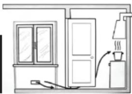
natural_image
Simple line drawing of a kitchen or bathroom interior with a door, cabinet, and stove (no text or symbols)Enlarging the Ventilation slots between the window and floor - Fig. B
INSTALLATION
C Intensive and prolonged use of the appliance may necessitate supplemental ventilation, e.g. opening a window or increasing the power of the air intake system (if present).
D Liquefied petroleum gases are heavier than air and, as a result, settle downwards. Rooms in which LPG tanks are installed must be fitted with ventilation openings to the outside in order to allow the gas to escape in the event of a leak. Therefore, LPG tanks, whether empty or partially full, must not be installed or stored in rooms or spaces below ground level' (cellars, etc.). It is also a good idea to keep only the tank currently being used in the room, making sure that it is not near sources of heat (ovens, fireplaces, stoves, etc.) that could raise the internal temperature of the tank above 50°C.
E Overhead clearances—(Measurement A) Rangehoods and exhaust fans shall be installed in accordance with the manufacturer's relevant instructions. However, in no case shall the clearance between the highest part of the hob of the gas cooking appliance and a range hood be less than 600 mm or, for an overhead exhaust fan, 750 mm.
Side clearances—(Measurements B, & C) Where B, measured from the periphery of the nearest burner to any vertical combustible surface, or vertical combustible surface covered with toughened glass or sheet metal, is less than 200 mm, the surface shall be protected to a height C of not less than 150 mm above the hob for the full dimension (width or depth) of the cooking surface area. Where the gas cooking appliance is fitted with a 'splashback', protection of the rear wall is not required.
F In the event the cooktop is not installed above a built-in oven, a wood panel must be inserted as insulation. This panel must be placed at least 30 mm from the bottom of the cooktop itself.
IMPORTANT // When installing the hob above a built-in oven, the oven should be placed on two wooden strips; in the case of a joining cabinet surface, remember to leave a space of at least 45 x 560 mm at the back.

text_image
A B CINSTALLATION

text_image
560 mm. 45 mm. 60 cm² 360 cm² 120 cm² 180 cm²When installing on a built-in oven without forced ventilation, ensure that there are air inlets and outlets for ventilating the interior of the cabinet adequately.
The gas cooktop should be connected to the gas-supply by an authorised person only. During installation of this product it is essential to fit an approved gas tap to isolate the supply from the appliance for the convenience of any subsequent removal or servicing. Connection of the appliance to the gas mains or liquid gas must be carried out according to the prescribed regulation in force, and only after it is ascertained that it is adaptable to the type of gas to be used. If not, follow the instructions indicated in the section “Gas Conversion – Natural Gas and Universal LPG”. In the case of connection to liquid gas, by tank, use pressure regulators that conform to the regulation in force.
IMPORTANT // For safety, for the correct regulation of gas use and long life of the appliance, ensure that the gas pressure conforms to the indications given in the Product Specification section of this manual under the heading “Nozzle and burner characteristics”.
CONNECTION TO NON-FLEXIBLE TUBE
Copper or Steel // Connection to the gas source must be done in such a way as to not create any stress points at any part of the appliance. The appliance is fitted with an adjustable, "L" shaped connector and a gasket for the attachment to the gas supply. Should this connector have to be turned, the gasket must be replaced (supplied with the appliance). The feeding connector of the gas to the appliance is threaded 1/2" gas male cylinder.
CONNECTION TO FLEXIBLE HOSE
The gas feed connector to the appliance is a threaded, male 1/2" connector for round gas pipe. Only use pipes and sealing gaskets that that conform to the standards currently in force. Flexible hose must be certified to AS1869 class B or D 10mm in diameter and no longer than
INSTALLATION
1200mm long. The hose must not be kinked or be able to touch any hot surface. The supply connection point must be accessible when installed.
GAS LEAKAGE AND OPERATION CHECK
The appliance must be tested by the installer before leaving. Check all burner flames are blue in colour, stable and completely ignite at both high and low flame settings with no appreciable yellow tipping, carbon deposition, lifting, floatinglighting back or objectionable odour. Test burners individually and in combination.
ELECTRICAL CONNECTION
The cooktops fitted with a tripolar electrical supply cord are designed to be used with alternating current according to the indications on the rating plate located under the cooktop. The earth wire can be identified by its yellow-green colour. In the case of installation over a built-in electric oven, the electrical connections for the cooktop and oven should be independent, not only for safety purposes, but also to facilitate removal of one or both in the future.
ELECTRICAL CONNECTION FOR GAS COOKTOP
The supply cord has been fitted with a 10A 3 pin plug. The power supply cord must be positioned so that it does not reach a temperature in excess of 50degC above room temperature at any point.
Before actual connection make sure that:
- The fuse and electrical system can withstand the load required by the appliance;
- That the electrical supply system is equipped with an efficient earth hook-up according to the norms and regulations prescribed by law;
- That the plug and switch are easily accessible after installation.
Important // the wires in the mains lead are coloured in accordance with the following code: Green & Yellow - Earth
Blue - Neutral
Brown - Live
As the colours of the wires in the mains lead may not correspond with the coloured markings identifying the terminals in your plug, proceed as follows: Connect the Green & Yellow wire to terminal marked "E" or coloured Green or Green & Yellow.
Connect the Brown wire to the terminal marked "L" or coloured Red.
Connect the Blue wire to the terminal marked "N" or coloured Black.
INSTALLATION
GAS CONVERSION - NATURAL GAS AND UNIVERSAL LPG
The cooktop is factory fitted with Natural Gas Injectors. To adapt the cooktop to a different type of gas than that for which it was designed, (see the sticker under the hob or on the packaging), the burner nozzles must be changed, as follows:
- Remove the pan supports and slide the burners out of the cooktop.
- Unscrew the nozzles using a 7mm socket wrench and replace them with those for the new type of gas. (See the product specification "Burner and Nozzle Specifications").
- Reassemble the parts following the instructions in reverse order.
- On completing the operation, replace the old rating label with the one showing the new type of gas; the sticker is available from our Service Centres.
- If the gas pressure is different than that prescribed, a pressure regulator must be installed at the source, in compliance with national standards governing the use of piped gas regulators.
REGULATION OF AIR SUPPLY TO THE BURNER
The burners do not need any primary air regulator.
SETTING THE MINIMUM REGULATION
NOTICE // In the case of liquid gas, the regulation screw must be fully screwed in (clockwise).
- Turn the gas valve to minimum.
- Remove the knob and turn the regulator screw (positioned either on the side of the top or inside the shaft - Fig. A and B) clockwise until the flame becomes small but regular.
- Make sure that, when the knob is turned rapidly high to low, the flame does not go out.
- In the event of a malfunction on appliances with the security device (thermocouple) when the gas supply is set at minimum, increase the minimum supply levels using the regulator screw in Fig. A-B.
- Once the adjustment has been made, apply sealing wax, or a suitable substitute, to the old seals on the by-pass.

natural_image
Close-up of a mechanical component with a cylindrical shaft and threaded rod (no visible text or symbols)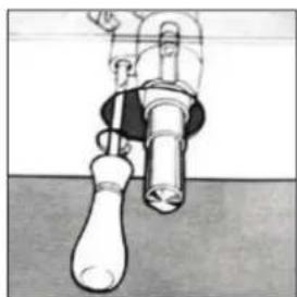
natural_image
Illustration of a mechanical valve or pump assembly with no visible text or symbolsPRODUCT SPECIFICATIONS
BURNERS AND NOZZLE SPECIFICATIONS
Gas consumption - Nominal gas consumption measured in MJ/h as per tables below.
| TGWF90G | Natural Gas Universal LPG | |||||
| Inj. diam.(mm) | MJ/h Gas press | Inj. diam.(mm) | MJ/h Gas press | |||
| Wok burner x 1 1.70 14.00 1.00 | 0.98 13.00 | 2.75 | ||||
| Rapid burner x 1 1.40 10.50 1.00 | 0.90 10.50 | 2.75 | ||||
| Semi-rapid burner x 2 | 1.10 | 6.00 | 1.00 | 0.70 | 6.00 | 2.75 |
| Auxiliary burner x 1 | 0.90 | 4.30 | 1.00 | 0.55 | 3.90 | 2.75 |
| Total NHGC | 40.80 | 39.40 | ||||
| TGWF60G | Natural Gas Universal LPG | |||||
| Inj. diam.(mm) | MJ/h Gas press | Inj. diam.(mm) | MJ/h Gas press | |||
| Wok burner x 1 1.70 14.00 1.00 | 0.98 | 13.00 2.75 | ||||
| Semi-rapid burner x 2 | 1.10 | 6.00 | 1.00 | 0.70 | 6.00 | 2.75 |
| Auxiliary burner x 1 | 0.90 | 4.30 | 1.00 | 0.55 | 3.90 | 2.75 |
| Total NHGC | 30.30 | 28.90 | ||||
| TG F60G | Natural Gas Universal LPG | |||||
| Inj. diam.(mm) | MJ/h Gas press | Inj. diam.(mm) | MJ/h Gas press | |||
| Rapid burner x 1 1.40 10.50 1.00 | 0.90 | 10.50 2.75 | ||||
| Semi-rapid burner x 2 | 1.10 | 6.00 | 1.00 | 0.70 | 6.00 | 2.75 |
| Auxiliary burner x 1 | 0.90 | 4.30 | 1.00 | 0.55 | 3.90 | 2.75 |
| Total NHGC | 26.80 | 26.40 | ||||
| TGWF30G | Natural Gas Universal LPG | |||||
| Inj. diam.(mm) | MJ/h Gas press | Inj. diam.(mm) | MJ/h Gas press | |||
| Wok burner x 1 1.70 14.00 1.00 | 0.98 | 13.00 2.75 | ||||
| Semi-rapid burner x 1 | 1.10 | 6.00 | 1.00 | 0.70 | 6.00 | 2.75 |
| Total NHGC | 20.00 | 19.00 | ||||
| TG F30G | Natural Gas Universal LPG | |||||
| Inj. diam.(mm) | MJ/h Gas press | Inj. diam.(mm) | MJ/h Gas press | |||
| Rapid burner x 1 1.40 10.50 1.00 | 0.90 | 10.50 2.75 | ||||
| Semi-rapid burner x 1 | 1.10 | 6.00 | 1.00 | 0.70 | 6.00 | 2.75 |
| Total NHGC | 16.50 | 16.50 | ||||
The appliance is supplied with a duplicate data plate, please attach to an adjacent surface for future reference.
WARRANTY TERMS & CONDITIONS
These Terms and Conditions apply only to Tisira products distributed in Australia and New Zealand by Arisit Pty Limited.
- This warranty applies for a period of 2 years parts and labour, Australia and New Zealand, commencing from date of purchase.
- Evidence of the date of purchase must be shown to the technician, when he calls, to obtain benefit under this warranty.
- This warranty applies only to the original purchaser/hire purchaser of this appliance and cannot be assigned or transferred. Failure to produce documentary proof of the date of original acquisition by the original purchaser will result in a charge being levied for work done, labour and parts supplied.
- This warranty does not apply to:
a) Serviceable items such as filters, fuses, light bulbs, door seals, drive belts, external hoses, etc.
b) Damage to body work, paint work, glass, trivets and plastic items (such as, but not limited to windows, covers, baskets, trays, worktops, door handles, control and kick panels.)
c) Corrosion & rust damage.
d) Damages/blockages caused by laundry or foreign objects.
A fee for service will be charged following warranty claims where no fault is found with the appliance.
- This warranty will not apply where:
a) The fault is caused by accident, misuse, oversuds, an infestation of vermin, fire, flood or the use of products not approved by Arisit Pty. Limited.
b) There has been a failure to comply, with the manufacturer's operating and installation instructions.
c) Service, modification or repair has been carried out by anybody other than an approved Tisira Service Technician.
d) The appliance has been used/installed anywhere other than a private dwelling, or where it has been used other than for domestic use.
e) The appliance is subject to a rental agreement.
- Any defective part that has been replaced becomes the property of Arisit Pty Limited.
- This warranty applies only to Tisira appliances purchased and installed in Australia and New Zealand.
- Loss of use of the appliance or consequential loss of any nature is not covered.
- A charge may be levied at the discretion of Arisit Pty Limited if the call is deemed unnecessary or if the cause of failure is traced to external sources such as, but not limited to: blown fuses, power failure, faulty installation, etc.
- Where the appliance, the subject of a warranty claim or repair, is used or installed more than TWENTY (20) kilometres from the nearest
Arisit Service Division or Authorised Service Agent, the cost of delivery to the nearest Service Division or travel costs for a technician or Authorised Service Agent shall be for the account of the Purchaser. Where a built-in appliance is located or installed outside the Arisit Authorised Service Agent's normal service area, additional travel and labour costs shall be the account of the Purchaser
- Arisit Pty Limited shall not under any circumstances be responsible in terms of this warranty for the replacement or repair of any part of the equipment which may have been damaged in transit, during and after installation or imperfections after installation.
- Losses caused by act of God, failure to obtain spare parts, strikes or lockouts are not covered.
- Service is offered during normal working hours only, also appliances to a have clear access in a serviceable area.
- This warranty does not effect your statutory rights.
- Our goods come with guarantees that cannot be excluded under the Australian Consumer Law. You are entitled to a replacement or refund for a major failure and for compensation for any other reasonably foreseeable loss or damage. You are also entitled to have the goods repaired or replaced if the goods fail to be of acceptable quality and the failure does not amount to a major failure.
We reserve the right to amend any of the above without prior notice.
Registration Form
To register for your warranty please complete and return this form to Arisit Pty Limited within 30 days of purchase.
t tisira
Where did you first hear about Tisira?
□ Advertising
In Store Display
☐ Other (please specify).
□ Tradesman's Recommendation
☐ Recommendation by Friend/Relative
Would you like any further information on other Tisira appliances? Please specify
□ Cooking
□ Dishwashers
□ Laundry
□ All
Please print in block letters
Date of Purchase / /
Name of Retailer
Address
Model Number
Serial Number
□ Mr □ Mrs □ Ms
Initials
Surname
Address
State Postcode
Telephone
PROOF OF PURCHASE
ATTACH YOUR PROOF OF PURCHASE FOR FUTURE REFERENCE
NOTES
NOTES
CONTACT DETAILS
AUSTRALIA
ARISIT PTY LIMITED
40-44 Mark Anthony Drive, Dandenong South, VIC 3175, Australia
P // 1300 762 219
F // 03 9768 0838
consumer.care@arisit.com
NEW ZEALAND
ARISIT PTY LIMITED
PO Box 68-140
Newton, Auckland 1145, New Zealand
P // 09 306 1020
F // 09 302 0077
sales@aristonappliances.co.nz
t tisira
TISIRA IS COMMITTED TO ONGOING RESEARCH AND DEVELOPMENT. EVERY EFFORT HAS BEEN MADE TO ENSURE ALL INFORMATION IN THIS USER MANUAL. IS CORRECT AT TIME OF GOING TO PRINT. DIMENSIONS SHOULD BE USED AS A REFERENCE ONLY AND ACTUAL DIMENSIONS SHOULD BE TAKEN FROM THE PHYSICAL PRODUCT ONLY.
MANUFACTURER RESERVES THE RIGHT TO CHANGE SPECIFICATIONS WITHOUT NOTICE.
www.tisira.com.au