
FOX USB - USB video transmitter Extron - Free user manual and instructions
Find the device manual for free FOX USB Extron in PDF.

| Product Type | Fiber Optic Extender for USB Peripherals (Transmitter and Receiver Pair) |
| Dimensions (H x W x D) | 1.0" x 4.3" x 3.0" (2.5 cm x 10.9 cm x 7.6 cm) |
| Weight | 0.25 lbs (0.1 kg) each unit |
| Power Supply | External; Input: 100-240 VAC, 50-60 Hz; Output: 12 VDC, 1 A, 12 W |
| USB Standards | USB 2.0 (480 Mbps), USB 1.1 (12 Mbps), USB 1.0 (1.5 Mbps) |
| Maximum Transmission Distance (Singlemode) | Up to 30 km (18.75 miles) |
| Maximum Transmission Distance (Multimode) | Up to 2 km (1.2 miles) with OM3/OM4 fiber |
| Receiver USB Hub Ports | 4 female USB Type A, each providing +5 VDC up to 500 mA |
| Transmitter Host Port | 1 female USB Type B |
| Fiber Optic Connectors | 2 LC connectors (Tx and Rx) |
| Front Panel Indicators | Power, Link, Host, and Hub LEDs |
| DIP Switch Settings | Emulation (down) or Bypass (up) for peripheral emulation |
| Enclosure Material | Metal, quarter rack width, 1 inch high |
| Mounting Options | Tabletop, rack shelf, under-desk, through-desk, projector mount (optional kits) |
| Cooling | Convection, vents on top and sides |
| Regulatory Compliance | CE, c-UL, UL, FCC Class A, ICES, VCCI Class A, C-tick |
| Operating Temperature | +32 to +122 °F (0 to +50 °C) |
| Storage Temperature | -40 to +158 °F (-40 to +70 °C) |
| Power Consumption (Transmitter) | 2.6 W (device), 3.4 W (device + power supply) |
| Power Consumption (Receiver) | 11.5 W (device), 13.9 W (device + power supply) |
| MTBF | 30,000 hours |
| Warranty | 3 years parts and labor |
Frequently Asked Questions - FOX USB Extron
User questions about FOX USB Extron
0 question about this device. Answer the ones you know or ask your own.
Ask a new question about this device
Download the instructions for your USB video transmitter in PDF format for free! Find your manual FOX USB - Extron and take your electronic device back in hand. On this page are published all the documents necessary for the use of your device. FOX USB by Extron.
USER MANUAL FOX USB Extron
Fiber Optic Extender for USB Peripherals
Safety Instructions • English
This symbol is intended to alert the user of important operating and maintenance (servicing) instructions in the literature provided with the equipment.
This symbol is intended to alert the user of the presence of uninsulated dangerous voltage within the product's enclosure that may present a risk of electric shock.
Caution
Read Instructions • Read and understand all safety and operating instructions before using the equipment.
Retain Instructions • The safety instructions should be kept for future reference.
Follow Warnings • Follow all warnings and instructions marked on the equipment or in the user information.
Avoid Attachments • Do not use tools or attachments that are not recommended by the equipment manufacturer because they may be hazardous.
Power sources • This equipment should be operated only from the power source indicated on the product. This equipment is intended to be used with a main power system with a grounded (neutral) conductor. The third (grounding) pin is a safety feature, do not attempt to bypass or disable it.
Power disconnection • To remove power from the equipment safely, remove all power cords from the rear of the equipment, or the desktop power module (if detachable), or from the power source receptacle (wall plug).
Power cord protection • Power cords should be routed so that they are not likely to be stepped on or pinched by items placed upon or against them.
Servicing • Refer all servicing to qualified service personnel. There are no user-serviceable parts inside. To prevent the risk of shock, do not attempt to service this equipment yourself because opening or removing covers may expose you to dangerous voltage or other hazards.
Slots and openings • If the equipment has slots or holes in the enclosure, these are provided to prevent overheating of sensitive components inside. These openings must never be blocked by other objects.
Lithium battery • There is a danger of explosion if battery is incorrectly replaced. Replace it only with the same or equivalent type recommended by the manufacturer. Dispose of used batteries according to the manufacturer's instructions.
Avertissement
This equipment has been tested and found to comply with the limits for a Class A digital device, pursuant to part 15 of the FCC rules. The Class A limits provide reasonable protection against harmful interference when the equipment is operated in a commercial environment. This equipment generates, uses, and can radiate radio frequency energy and, if not installed and used in accordance with the instruction manual, may cause harmful interference to radio communications. Operation of this equipment in a residential area is likely to cause interference; the user must correct the interference at his own expense.
NOTE: This unit was tested with shielded I/O cables on the peripheral devices. Shielded cables must be used to ensure compliance with FCC emissions limits. For more information on safety guidelines, regulatory compliances, EMI/EMF compatibility, accessibility, and related topics, see the "Extron Safety and Regulatory Compliance Guide" on the Extron website.
Conventions Used in this Guide
Notifications
WARNING: A warning indicates a situation that has the potential to result in death or severe injury.
ATTENTION: Attention indicates a situation that may damage or destroy the product or associated equipment.
NOTE: A note draws attention to important information.
Copyright
© 2012 Extron Electronics. All rights reserved.
Trademarks
All trademarks mentioned in this guide are the properties of their respective owners.
Contents
Introduction ...... 1
About this Guide 1
About the FOX USB Extender....1
Features....3
Installation and Operation......4
Mounting Overview 4
Connections 5
System Startup and Operation 6
Indications 6
Startup 7
Operation 7
Troubleshooting 8
Reference Information ...... 9
Specifications....9
Part Numbers....11
FOX USB Extender Part Numbers....11
Included Parts 11
Cables 11
Mounting the FOX USB Extender 12
Tabletop Use 12
Mounting 12
Introduction
WARNING: The FOX USB Extender Transmitter and Receiver units output continuous invisible light, which may be harmful to the eyes; use with caution.
- Do not look into the rear panel fiber optic cable connectors or into the fiber optic cables themselves.
-
Plug the attached dust caps into the optical transceivers when the fiber cable is unplugged.
-
About this Guide
• About the FOX USB Extender - Features
About this Guide
This guide contains information to install, configure, and operate the Extron Electronics FOX USB Extender.
About the FOX USB Extender
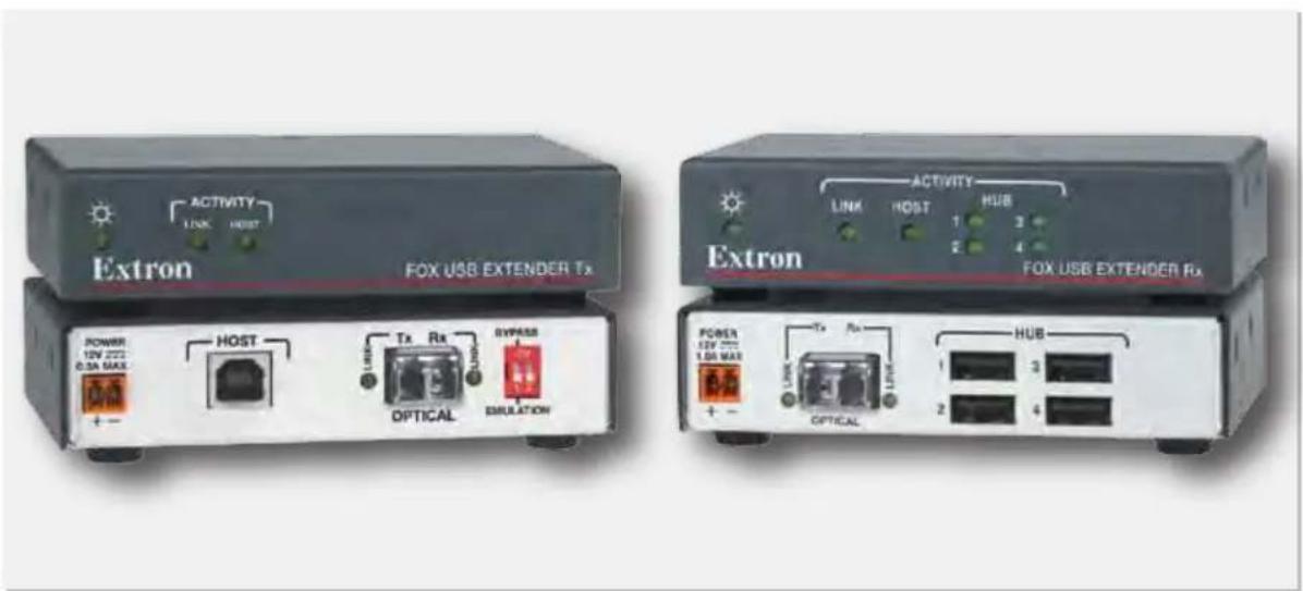
The FOX USB Extender (see figure 1, on the next page) is a USB transmitter and receiver pair that extends the usable distance of USB 1.0, 1.1, and 2.0 standards with data transfer rates up to 480 Mbps. The Extender is also compatible with the Extron FOX Matrix Switcher models (see figure 2, on the next page).
The transmitter and receiver are categorized by the type of fiber optic cable, multimode or singlemode, which define the effective range of transmission:
- Multimode — Long distance, up to 2 km (1.2 miles) (depending on the fiber cable)
- Singlemode — Very long distance, up to 30 km (18.75 miles)
NOTE: The multimode and singlemode units are physically and functionally identical, with the exception of the effective range of transmission. In this manual, any reference applies to either transmission mode model unless otherwise specified.
A FOX USB Extender system consists of a transmitter (Tx) and a receiver (Rx). The transmitter connects directly to a USB port on a PC or USB host. The receiver features a four port USB hub to connect multiple peripheral devices.
The FOX USB Extender complies with the USB 2.0 standard, supporting USB 2.0 (480 Mbps high speed), USB 1.1 (12 Mbps full speed), and USB 1.0 (1.5 Mbps low speed) for data transmission throughout the system. It also supplies +5 VDC (up to 500 mA) of power on each of the receiver USB peripheral ports.
The transmitter and receiver both feature a front panel USB host activity LED, power indicator, and a fiber cable Link LED for local or remote troubleshooting.
flowchart
graph TD
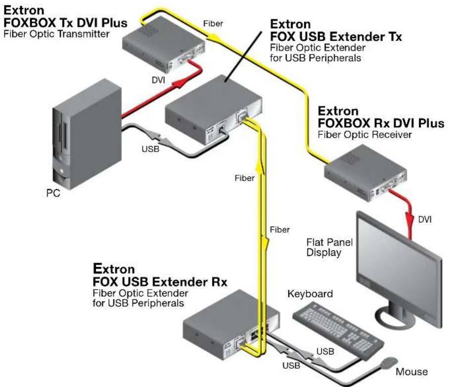
A["Extron FOXBOX Tx DVI Plus\nFiber Optic Transmitter"] -->|DVI| B["Extron FOX USB Extender Tx\nFiber Optic Extender for USB Peripherals"]
B -->|Fiber| C["Extron FOXBOX Rx DVI Plus\nFiber Optic Receiver"]
C -->|DVI| D["Flat Panel Display"]
D --> E["Keyboard"]
E --> F["USB"]
F --> G["Mouse"]
H["PC"] --> I["USB"]
I --> J["Fiber"]
J --> K["Extron FOX USB Extender Rx\nFiber Optic Extender for USB Peripherals"]
Figure 1. Typical FOX USB Transmitter and Receiver Application
flowchart
graph TD
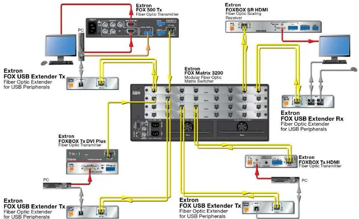
A["Extron FOX USB Extender Tx\nFiber Optic Extender for USB Peripherals"] --> B["Extron FOX 500 Tx\nFiber Optic Transmitter"]
B --> C["Extron FOX Matrix 3200\nModular Fiber Optic Matrix Switcher"]
C --> D["Extron FOX BOX SR HDMI\nFiber Optic Scaling Receiver"]
D --> E["Extron FOX USB Extender Rx\nFiber Optic Extender for USB Peripherals"]
C --> F["Extron FOX BOX Tx HDMI\nFiber Optic Transmitter"]
F --> G["Extron FOX USB Extender Tx\nFiber Optic Extender for USB Peripherals"]
G --> H["Extron FOX USB Extender Tx\nFiber Optic Extender for USB Peripherals"]
C --> I["Extron FOX BOX Tx DVI Plus\nFiber Optic Transmitter"]
I --> J["Extron FOX USB Extender Tx\nFiber Optic Extender for USB Peripherals"]
J --> K["Extron FOX USB Extender Tx\nFiber Optic Extender for USB Peripherals"]
A --> L["PC"]
L --> M["Computer"]
style A fill:#f9f,stroke:#333
style B fill:#ccf,stroke:#333
style C fill:#cfc,stroke:#333
style D fill:#fcc,stroke:#333
style E fill:#cff,stroke:#333
style F fill:#ffc,stroke:#333
style G fill:#cfc,stroke:#333
style H fill:#fcc,stroke:#333
style I fill:#ffc,stroke:#333
style J fill:#cfc,stroke:#333
style K fill:#fcc,stroke:#333
Figure 2. Typical FOX USB Transmitter and Receiver Application with Matrix Switcher
The FOX USB Extenders are in 3 inches deep, quarter rack width, 1 inch high metal enclosures. They can be set on a tabletop or mounted in a rack, behind a display, under or through furniture, or to a projector pole.
Features
- Transmits USB signals long distances over two fiber optic cables — Up to 30 km (18.75 miles) on singlemode cables.
- One inch high, quarter rack width, metal enclosures — With low profile enclosures, the transmitter and receiver can be discreetly installed in locations such as behind a plasma or LCD flat-panel display.
- External 100 VAC to 240 VAC, 50-60 Hz, international power supply — Included with each transmitter and receiver.
Installation and Operation
This sections details the installation of the FOX USB Extender, including:
- Mounting Overview
- Connections
• System Startup and Operation - Troubleshooting
Mounting Overview
The 3 inches deep, 1 inch high, quarter rack width FOX USB Extender transmitter and receiver can be placed on a tabletop, behind a display, mounted on a rack shelf, or mounted under a desk or tabletop. The receiver can be mounted on a projector bracket.
Mounting details are included in "Mounting the FOX USB Extender" in the "Reference Information" section on page 12. Mounting instructions are included with each optional mounting kit.
ATTENTION: Installation and service must be performed by authorized personnel only.
Connections

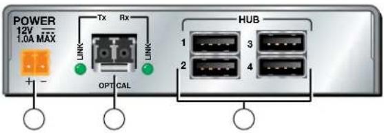
Figure 3. Rear Panel Connectors
① Power input connector — Connect external power supplies to these 2-pole, 3.5 mm captive screw connectors. If the USB port of a connected PC or laptop is capable of providing USB power, an external supply for the transmitter is not required.
ATTENTIONS: • Always use a power supply supplied by or specified by Extron for use with the FOX USB Extender Series. Use of an unauthorized power supply voids all regulatory compliance certification and may cause damage to the supply and the FOX USB Extenders.
- Unless otherwise stated, the AC/DC adapters are not suitable for use in air handling spaces or in wall cavities. The power supply is to be located within the same vicinity as the Extron AV processing equipment in an ordinary location, Pollution Degree 2, secured to the equipment rack within the dedicated closet, podium or desk.
- The installation must always be in accordance with applicable provisions of National Electrical Code ANSI/NFPA 70, article 75 and the Canadian Electrical Code part 1, section 16. The power supply shall not be permanently fixed to building structure or similar structure.
② USB host connector — This USB Type A connector supports a computer host. Do not connect a device at this time; see "Startup" on page 7.
③ Fiber optic connectors and LEDs — Connect two fiber optic cables between the LC connectors on the transmitter and receiver. Connect each Tx port to the Rx port on the opposite unit (see the drawing at right).
WARNING: These units output continuous invisible light, which may be harmful to the eyes; use with caution. For additional safety, plug the attached dust caps into the optical transceivers when the fiber cable is unplugged.
NOTE: Use the proper fiber cable for your transmitter and receiver pair. Typically, singlemode fiber has a yellow jacket and multimode cable has an orange or aqua jacket.

Tx Link and Rx Link LEDs — When lit, the link is active (light is present, either transmitted or received).
④ DIP Switch —
Emulation (down) position — Enables the peripheral emulation, which is internal to the transmitter. This emulation allows connected hosts, some of which require a connected USB device, to boot up normally.
Bypass (up) position — Bypasses the internal peripheral emulation of the transmitter.
NOTES: • The FOX USB Extender system supports up to four USB hubs connected to the receiver when the DIP switch on the transmitter is in the Bypass position. The system supports up to three hubs when the DIP switch is in the Emulation position. • DIP switch 2 has no function.
⑤ Hub connectors — These female USB Type A connectors support up to four USB devices. Do not connect devices at this time; see "Startup" on the next page.
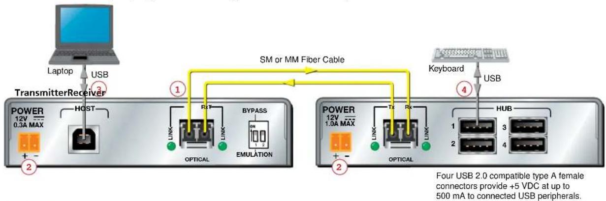
The connections are USB 2.0 compatible, and can provide +5 VDC at up to 500 mA to connected USB peripherals requiring power.
System Startup and Operation
Indications
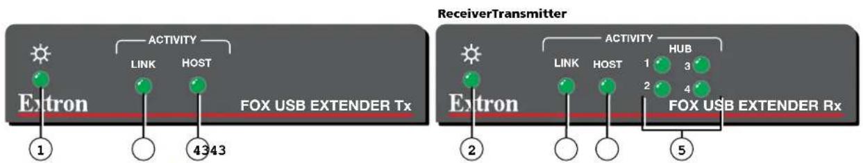
Figure 4. Front Panel Indications
① Power LED (transmitter) — Indicates that the transmitter is receiving power from an external power supply.
② Power LED (receiver) — Indicates that the receiver is receiving power from an external power supply.
③ Link LED — Indicates that the unit is receiving light on its rear panel Rx connector.
NOTE: The receiver Link LED indicates light from the transmitter. The transmitter Link LED indicates light from the receiver.
④ Host LED — Indicates that the Extender is communicating with the computer connected to the rear panel Host port on the transmitter.
⑤ Hub LEDs — Indicate that the receiver is communicating with the USB peripheral connected to the rear panel Hub port on the receiver.
Startup
For proper operation, the transmitter, receiver, USB host, and peripherals must be connected properly as shown in figure 5 and in the sequence described below.
flowchart
graph TD
    A["Laptop"] -->|USB| B["Transmitter Receiver"]
    B --> C["POWER 12V 0.3A MAX"]
    C --> D["HOST"]
    D --> E["OPTICAL"]
    E --> F["RIT"]
    F --> G["BYPASS"]
    G --> H["EMULATION"]
    H --> I["TX"]
    I --> J["POWER 12V 1.0A MAX"]
    J --> K["TX"]
    K --> L["OPTICAL"]
    L --> M["HUB"]
    M --> N["Keyboard"]
    N --> O["USB"]
    style A fill:#f9f,stroke:#333
    style O fill:#bbf,stroke:#333
    note right of B SM or MM Fiber Cable
        Four USB 2.0 compatible type A female connectors provide +5 VDC at up to 500 mA to connected USB peripherals.
Figure 5. FOX USB Extender Connection Guide with Two External Supplies
- Power down the transmitter, receiver, USB host computer (connected to the transmitter) and all peripherals and devices that will be connected to the receiver.
- Connect fiber cables between the transmitter and receiver ( ① on figure 5).
- Connect external power supplies to the transmitter and receiver and apply power (②).
The Power LEDs and Link LEDs on both units light to indicate proper link cable connection between the transmitter and receiver.

LINK
- Connect a type A-B cable between the FOX USB Extender transmitter Host port and the USB host (a computer or other USB host device) (③).
- Apply power to the host computer and boot the computer.
After the computer starts, the transmitter Host LED lights, indicating communication between the PC and transmitter hub controller.
HOST
Shortly after, the receiver Host LED lights indicating communication between the transmitter and receiver.

HOST

- Connect USB peripherals, such as keyboards and mice, to the FOX USB Extender receiver using USB 2.0 compatible cables (4).
As each peripheral is recognized by the PC, the appropriate FOX USB Extender Hub LED on the front panel of the receiver lights.
HUB


Operation
No drivers are required for a host to function with the FOX USB Extenders. The transmitter is detected by Windows and appropriate USB drivers are loaded. Certain USB peripherals, such as gaming keyboards, USB interactive whiteboards, scanners, printers, and similar devices, require specific drivers to be installed on the host computer. See the USB device installation instructions or the peripheral manufacturer website to obtain drivers.
After the transmitter, the receiver, the USB host, and the peripherals are connected and powered up, and the appropriate drivers are loaded for the peripherals, the system is fully operational. If any problems are encountered, verify that the cables are routed and connected properly and the latest drivers for each peripheral are installed.
Troubleshooting
USB signals are generally reliable but are susceptible to bad connections or cables that are too long. To avoid the loss of data and communications, follow these guidelines:
- The transmitter host USB cable and receiver hub port USB cables should not exceed 10 feet (3 m).
- Avoid or limit the use of adapters.
- The FOX USB Extender works as described in point-to-point applications. Do not use additional adapters, patch panels, or couplers with the host USB cables, hub USB cables, or fiber optic cables. Additional links in the signal chain can result in the reduction of signal integrity and overall cable length performance.
When properly connected and operating, both transmitter and receiver Power LEDs, Link LEDs and Host LEDs are lit. The Hub LED for each connected peripheral recognized by the host PC is also lit.
Front panel LEDs may also be useful for troubleshooting. The table on the next page outlines operating details indicated by the LEDs.
Table 1. System Troubleshooting
| Transmitter Receiver | ||||
| LED Lit Unlit Lit Unlit | ||||
| The 12 VDC supply is connected and operating properly or the host is properly supplying power. | The 12 VDC supply is not connected or is defective.If a transmitter supply is not being used, the USB host is either not on or not providing power, or the USB cable is disconnected. | The 12 VDC supply is connected and operating properly. | The 12 VDC supply is not connected or defective. | |
| Link | Both the transmitter and receiver have power and the fiber optic cables are connected properly.(The transmitter Link LED indicates light from the receiver.) | If both Power LEDs are on, the fiber optic cable is not connected.If a transmitter supply is not being used, the USB host is either not on or is not providing power. | Both the transmitter and receiver have power and the fiber optic cables are connected properly.(The receiver Link LED indicates light from the transmitter.) | If both Power LEDs are on, the fiber optic cables are not connected or are improperly wired.If either Power LED is off, see the Power LED troubleshooting instructions above. |
| Host | When the transmitter Host LED is on, the transmitter is communicating with the host computer. | If the transmitter Host LED is on, the USB cable is not connected.The LED blinks if the transmitter is not communicating with the receiver. | Lights when communication with the host computer is established. | The host USB port is not connected or the host is not communicating. |
| Hub | N/A N/A Lights when the peripheral | on the USB port has been recognized by the host computer. | The peripheral on the USB port has not been recognized or is improperly connected. | |
If your problems persist, call the Extron S3 Sales & Technical Support Hotline. See the contact numbers on the last page of this guide for the Extron office nearest you
Reference Information
This section provides the specifications, part numbers, and accessories, and mounting instructions for the FOX USB Extender. Topics that are covered include:
- Specifications
- Part Numbers
- Mounting the FOX USB Extender
Specifications
USB
USB standards.... USB 2.0, USB 1.1, USB 1.0 compatible
USB data rates..... Low speed (1.5 Mbps), full speed (12 Mbps), high speed (480 Mbps)
Signal transmission distance .... 30 km (18.64 miles) with singlemode (SM) cables
300 m (985') with 62.5 μm OM1 multimode (MM) cables
1 km (3280') with 50 μm OM2 multimode (MM) cables
2 km (6561') with 50 μm OM3/OM4 2000 MHz bandwidth laser optimized
multimode cables
NOTE: Operating distance is approximate. These are typical maximum distances that may vary depending on factors such as fiber type, fiber bandwidth, connector splicing, losses, modal or chromatic dispersion, environmental factors, and kinks.
USB host — FOX USB Extender Tx
Number/signal type 1 USB (supports USB 2.0, 1.1, 1.0 speeds)
Connectors 1 female USB type B
Interconnection between transmitter and receiver
Connectors 2 LC connectors
Nominal peak wavelength.... 850 nm for MM, 1310 nm for SM
Data rate 600 Mbps
Transmission power.... -5 dBm, typical
Maximum receiver sensitivity
Singlemode .... -18 dBm, typical
Multimode.... -12 dBm, typical
Optical loss budget
Singlemode 13 dB, maximum
Multimode.... 7 dB, maximum
USB hub — FOX USB Extender Rx
Number/signal type ...... (1) 4-port USB hub
Connectors 4 female USB type A
General
Power supply...... External
Input: 100-240 VAC, 50-60 Hz
Output: 12 VDC, 1 A, 12 watts
Power consumption
Device
FOX USB Extender Tx ..... 2.6 watts
FOX USB Extender Rx ...... 11.5 watts
Device and power supply
FOX USB Extender Tx ...... 3.4 watts
FOX USB Extender Rx ...... 13.9 watts
Temperature/humidity ...... Storage: -40 to +158 °F (-40 to +70 °C) / 10% to 90%, noncondensing
Operating: +32 to +122 °F (0 to +50 °C) / 10% to 90%, noncondensing
Cooling...... Convection, vents on top and sides
Thermal dissipation
Device
FOX USB Extender Tx 8.8 BTU/hr
FOX USB Extender Rx ..... 10.1 BTU/hr
Device and power supply
FOX USB Extender Tx ..... 11.4 BTU/hr
FOX USB Extender Rx...... 18.3 BTU/hr
Mounting
Rack mount...... Yes, with optional rack shelf or rack mounting brackets
Furniture or wall mount ...... Yes, with optional mounting kits
Enclosure type.... Metal
Enclosure dimensions 1.0" H x 4.3" W x 3.0" D
(2.5 cm H x 10.9 cm W x 7.6 cm D)
(Depth excludes connectors.)
Product weight.... 0.25 lbs (0.1 kg)
Shipping weight.... 1 lb (<1 kg)
Vibration.... ISTA 1A in carton (International Safe Transit Association)
Regulatory compliance
Safety...... CE, c-UL, UL
EMI/EMC CE, C-tick, FCC Class A, ICES, VCCI Class A
Environmental...... Complies with the appropriate requirements of RoHS, WEEE
MTBF 30,000 hours
Warranty 3 years parts and labor
NOTES: • All nominal levels are at ±10%.
- Specifications are subject to change without notice.
Part Numbers
FOX USB Extender Part Numbers
| Extender part numbers Part number | |
| FOX USB Tx (SM) 60-1234-12 | |
| FOX USB Rx (SM) 60-1234-22 | |
| FOX USB Tx (MM) 60-1234-11 | |
| FOX USB Rx (MM) 60-1234-21 |
Included Parts
These items are included in each order for a FOX USB Extender transmitter or receiver:
| Included part numbers Part number | |
| 12V, 1A external power supply | |
| IEC power cords (qty. 1) | |
| SFP Module (SM or MM, depending on the model) | |
| 10' LC-LC duplex patch cable (SM or MM, depending on the model) | |
| Rubber feet (qty. 4) | |
| FOX USB Extender Setup Guide |
Cables
Fiber cable assemblies
| MHR Mini High Resolution Cable Part Number | |
| 4LC MM LC to LC Multimode Fiber Optic Cable Assemblies 26-652-nn | |
| 2LC OM4 MM P LC to LC Laser-Optimized Multimode Fiber Optic Cable Assemblies — Plenum | 26-671-nn |
| 2LC SM P LC to LC Bend-Insensitive Singlemode Fiber Optic Cable Assemblies — Plenum | 26-670-nn |
Bulk fiber cable and termination tools
| RG6 Super High Resolution Cable Part Number | |
| OM4 MM P/2K Plenum 2 km (6,562 foot) Spool 22-225-02 | |
| SM P/2K Plenum 2 km (6,562 foot) Spool 22-223-02 | |
| Fiber Optic Termination Kit Termination Kit 100-656-01 | |
| QLC MM/10 Fiber Optic connectors, multimode, qty. 10 101-018-01 | |
| QLC SM/10 Fiber Optic connectors, singlemode, qty. 10 | 101-017-01 |
Mounting the FOX USB Extender
ATTENTION: Installation and service must be performed by authorized personnel only.
Any of the units can be placed on a tabletop or behind a display, mounted on a rack shelf, or mounted under or through a desk or other furniture. The receiver can be mounted to a projector bracket.
Tabletop Use
Affix the four included rubber feet to the bottom of the unit and place it in any convenient location.
Mounting
If desired, mount the unit using any of the following optional kits:
• RSF 123 3.5-inch deep rack shelf kit (part number 60-190-20)
• RSB 123 3.5-inch deep rack shelf (part number 60-604-21)
• RSU 126 6-inch deep universal rack shelf kit (part number 60-190-10)
• RSB 126 6-inch deep basic rack shelf (part number 60-604-11)
• RSU 129 9.5-inch deep universal rack shelf kit (part number 60-190-01)
• RSB 129 9.5-inch deep basic rack shelf (part number 60-604-02)
• MBB 100 Back of the rack mounting kit (part number 70-367-01)
• MBU 125 under-desk mounting kit (part number 70-077-01)
• MBD 129 through-desk mounting kit (part number 70-077-02)
• PMK 300 projector mount kit (part number 70-374-01)
• PMK 350 low profile projector mount kit (part number 70-563-03)
Follow the instructions included with the kit.
UL Guidelines for Rack Mounting
The following Underwriters Laboratories (UL) guidelines pertain to the installation of a FOX USB Extender unit into a rack.
- Elevated operating ambient — If installed in a closed or multi-unit rack assembly, the operating ambient temperature of the rack environment may be greater than room ambient. Therefore, consider installing the equipment in an environment compatible with the maximum ambient temperature specified by Extron (Tma = +122 °F [+50 °C]).
- Reduced air flow — Installation of the equipment in a rack should be such that the amount of air flow required for safe operation of the equipment is not compromised.
- Mechanical loading — Mounting of the equipment in the rack should be such that a hazardous condition is not achieved due to uneven mechanical loading.
- Circuit overloading — Consideration should be given to the connection of the equipment to the supply circuit and the effect that overloading of the circuits might have on overcurrent protection and supply wiring. Appropriate consideration of equipment nameplate ratings should be used when addressing this concern.
- Reliable earthing (grounding) — Reliable earthing of rack-mounted equipment should be maintained. Particular attention should be given to supply connections other than direct connections to the branch circuit (such as the use of power strips).
Extron Warranty
Extron Electronics warrants this product against defects in materials and workmanship for a period of three years from the date of purchase. In the event of malfunction during the warranty period attributable directly to faulty workmanship and/or materials, Extron Electronics will, at its option, repair or replace said products or components, to whatever extent it shall deem necessary to restore said product to proper operating condition, provided that it is returned within the warranty period, with proof of purchase and description of malfunction to:
USA, Canada, South America, and Central America:
Extron Electronics
1001 East Ball Road
Anaheim, CA 92805
U.S.A.
Japan:
Extron Electronics, Japan
Kyodo Building, 16 Ichibancho
Chiyoda-ku, Tokyo 102-0082
Japan
Europe and Africa:
Extron Europe
Hanzeboulevard 10
3825 PH Amersfoort
The Netherlands
China:
Extron China
686 Ronghua Road
Songjiang District
Shanghai 201611
China
Asia:
Extron Asia
135 Joo Seng Road, #04-01
PM Industrial Bldg.
Singapore 368363
Singapore
Middle East:
Extron Middle East
Dubai Airport Free Zone
F12, PO Box 293666
United Arab Emirates, Dubai
This Limited Warranty does not apply if the fault has been caused by misuse, improper handling care, electrical or mechanical abuse, abnormal operating conditions, or if modifications were made to the product that were not authorized by Extron.
NOTE: If a product is defective, please call Extron and ask for an Application Engineer to receive an RA (Return Authorization) number. This will begin the repair process.
USA: 714.491.1500 or 800.633.9876
Europe: 31.33.453.4040
Asia: 65.6383.4400
Japan:
81.3.3511.7655
Units must be returned insured, with shipping charges prepaid. If not insured, you assume the risk of loss or damage during shipment. Returned units must include the serial number and a description of the problem, as well as the name of the person to contact in case there are any questions.
Extron Electronics makes no further warranties either expressed or implied with respect to the product and its quality, performance, merchantability, or fitness for any particular use. In no event will Extron Electronics be liable for direct, indirect, or consequential damages resulting from any defect in this product even if Extron Electronics has been advised of such damage.
Please note that laws vary from state to state and country to country, and that some provisions of this warranty may not apply to you.
| Extron Headquarters+1.800.633.9876 (Inside USA/Canada Only)Extron USA - West Extron USA - East+1.714.491.1500 +1.919.850.1000+1.714.491.1517 FAX +1.919.850.1001 FAX | Extron Europe+800.3987.6673(Inside Europe Only)+31.33.453.4040+31.33.453.4050 FAX | Extron Asia+800.7339.8766(Inside Asia Only)+65.6383.4400+65.6383.4664 FAX | Extron Japan+81.3.3511.7655+81.3.3511.7656 FAX | Extron China+4000.398766+86.21.3760.1568+86.21.3760.1566 FAX | Extron Middle East+971.4.2991800+971.4.2991880 FAX | Extron Korea+82.2.3444.1571+82.2.3444.1575 FAX | Extron India1800.3070.3777Inside India Only+91.80.3055.3777+91.80.3055.3737 FAX |
- Safety Instructions • English
- Caution
- Avertissement
- Conventions Used in this Guide
- Notifications
- Copyright
- Trademarks
- Contents
- Introduction ...... 1
- Installation and Operation......4
- Reference Information ...... 9
- Introduction
- About this Guide
- About the FOX USB Extender
- Features
- Installation and Operation
- Mounting Overview
- Connections
- ④ DIP Switch —
- ⑤ Hub connectors — These female USB Type A connectors support up to four USB devices. Do not connect devices at this time; see "Startup" on the next page.
- System Startup and Operation
- Startup
- Operation
- Troubleshooting
- Reference Information
- Specifications
- USB
- USB host — FOX USB Extender Tx
- Interconnection between transmitter and receiver
- USB hub — FOX USB Extender Rx
- General
- Part Numbers
- Included Parts
- Cables
- Mounting the FOX USB Extender
- Tabletop Use
- Mounting
- UL Guidelines for Rack Mounting
- Extron Warranty
- USA, Canada, South America, and Central America:
- Japan:
- Europe and Africa:
- China:
- Asia:
- Middle East:
Brand : Extron
Model : FOX USB
Category : USB video transmitter