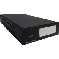
HVWCTRL - Controller AG Neovo - Free user manual and instructions
Find the device manual for free HVWCTRL AG Neovo in PDF.


| Product Type | IP Controller |
| Brand | AG Neovo |
| Model | HVWCTRL |
| Power Supply | 12V DC, 1A |
| Network Interface | Gigabit Ethernet (RJ45) |
| Protocol Support | TCP/IP, HTTP, Telnet |
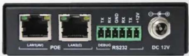
| Control Port | RS-232 (via Phoenix connector) |
| Video Wall Capability | Up to 2x2 (configurable) |
| Max Transmitters Displayed | 6 |
| Compatible Transmitters | HVWCIP-T (firmware V2.83) |
| Compatible Receivers | HVWCIP-R (firmware V2.82) |
| iPad App | VisualM25 (iOS 7+) |
| PC Software | HDMI over IP Console V7.0.0 |
| Firmware Version | V1.5/V5.10 |
| Operating Temperature | 0°C to 50°C |
| Relative Humidity | <80% (non-condensing) |
| PoE Support | No (requires external adapter) |
| CEC Support | Yes (for display power control) |
| API Commands | Telnet-based for matrix and video wall switching |
Frequently Asked Questions - HVWCTRL AG Neovo
User questions about HVWCTRL AG Neovo
0 question about this device. Answer the ones you know or ask your own.
Ask a new question about this device
Download the instructions for your Controller in PDF format for free! Find your manual HVWCTRL - AG Neovo and take your electronic device back in hand. On this page are published all the documents necessary for the use of your device. HVWCTRL by AG Neovo.
USER MANUAL HVWCTRL AG Neovo
HVWCTRL IP Controller
Video Wall SETUP

Installation Manual


TABLE OF CONTENTS
Contents
Chapter 1: APP GUIDE FOR THE HVWCIP-SERIES DEVICES....2
1.1 ABOUT THIS DOCUMENT 2
1.2 GENERAL INSTRUCTIONS ...... 2
Chapter 2: OVERVIEW....3
Chapter 3: BEFORE INSTALLATION....4
Chapter 4: NETWORK BANDWIDTH CALCULATOR....5
Chapter 5: VIDEO WALL SETUP....7
Chapter 6: CREATE AND CONFIGURE VIDEOWALL....8
Chapter 7: IPAD APP SETUP....15
Chapter 8: ADVANCE SETTING TABS....18
Chapter 9: SIMPLE API COMMANDS....20
APP GUIDE FOR THE HVWCIP-SERIES DEVICES
1.1 ABOUT THIS DOCUMENT
This document explains how to configure the HVWCIP-Series devices to work with an iPad App and control PC software.
Software version: V7.0.0
Firmware version: V1.5/V5.10 (5.11)
The firmware and software versions listed in this document have been tested within the recommended settings the units can support and are fully supported by AG Neovo.
It is recommended that users read this entire document before attempting both setup and firmware updates and fully understand all the steps and procedures outlined in this document.

WARNING – Please make sure when using this guide for an exciting setup all of the following items are available:
- HVWCIP-T and HVWCIP-R with 12V 1A power supplies
- HVWCTRL IP Controller
- CAT5/6 cables
- Wireless Gigabit Router with 802.11/a/b/g/n 2.4 GHz; 5 GHz
- Network switch
- RS-232 to bare wire for phoneix RS-232 out
- 3.5mm headphones jack to bare wire (external audio)
- Wireless Gigabit Router with 802.11/a/b/g/n 2.4 GHz; 5 GHz
- 6 x Ethernet (RJ45 Patch Cable 6 to 3m (10ft) or within the setup CAT5/6 cable runs)
1.2 GENERAL INSTRUCTIONS
- Before beginning the setup guide or firmware upgrade ensure that the HVWCIP-Series unit are powered by the supplied power supply 12V 1A or to proper POE specifications.
- PC Requirements-Windows® XP/ Windows Vista®/ Windows® 7 (Windows® 8/ Windows® 10 are available)
- Ensure Laptop or desktop is plugged in to AC power during the update process. It is not recommended to use battery power during the setup/upgrade. Do not unplug power from the unit at any time during the firmware update process as this could lead to malfunctions.
OVERVIEW
The following table describes the firmware version the devices has to be at to ensure a stable working environment and IOS compatibility.
Products and Versions
| Products Versions | |
| HVWCTRL- iPad & PC Software V7.0.0 | |
| HVWCTRL V1.5/ V5.1.0 (V5.1.1) | |
| HVWCIP-T (Transmitter) V2.83 | |
| HVWCIP-R (Receiver) V2.82 | |
BEFORE INSTALLATION
- Place the product in a level and stable location. If the product falls, it may cause damage or malfunction to components within the casing.
- Do not place the product in temperatures under 0^ or over 50^ . High humidity may also cause the unit to malfunction.
- Use the DC power adapter with correct specifications supplied with the unit. If improper power supply is used, this may result in malfunction of the unit and may cause fire.
- Do not twist or pull by force the ends of the UTP/HDMI cable. It will cause malfunction.
Please follow the connection diagram as below:

flowchart
graph TD
    subgraph HVWCIP-T
        A1["HDMI SOURCE 1"] --> B1["HDMI SOURCE 2"]
        A2["HDMI SOURCE 3"] --> B2["HDMI SOURCE 3"]
    end

    subgraph HVWCIP-R
        C1["PC Software control or control with third party systems"] --> D1["HVWCTRL"]
        E1["CRESTRON"] --> D1
        F["AMX"] --> D1
    end

    G["Transmitters can be up to 100m (330ft) from the Network Switch"]
    H["GIGABIT SWITCH with MULTICAST & IGMP 2.0"] --> I["HVWCTRL"]
    J["Video Wall 2x2"] --> K["LIVE PREVIEW IN APP"]
    L["IPAD CONTROL SOFTWARE"] --> M["Receivers can be up to 100m (330ft) to HD Display"]
    N["Available on the App Store"] --> O["Available on the App Store"]
    style HVWCIP-T fill:#f9f,stroke:#333
    style HVWCIP-R fill:#f9f,stroke:#333

NETWORK BANDWIDTH CALCULATOR
The following notes and math equations below allow the installer to properly calculate and establish the right network environment for streaming live video across the network and iPad.
Control Device : iPad Air/ Air2/Mini
iOS Version: Compatible with iOS 7 and above.
Wireless device: Should have Wi-Fi frequency band (2.4GHz and 5GHz)
Equation for calculating the video bandwidth allowed
Tband=1.3*i*(6+VW)*0.5 aka True bandwidth
Pband=Wifi bandwidth/3 (Unit: M) aka Project bandwidth
Project proposal should be Tband<Pband.
Parameters:
Constant 1.3:1.3 is the network packets consumption coefficient.
Variable i: the number of the iPad which connected to the same network of the IP controller (HWWCTRL) and has the APP running.
Constant 6: this number is the max number of Transmitter show on the HVWCTRL-iPad & PC Software task bar App.
Variable VW: the numbers of the video wall configuration show on the HVWCTRL-iPad & PC software.
Constant 0.5: this numbers is the Transmitter preview stream bandwidth to the HVWCTRL software.
Variable Wifi bandwidth/3: this digit is the wireless router protocol (Example 802.11G=54mbps @ 2.4Ghz) or Access Point's rated bandwidth, on any project site the device would only use 1/3 of the bandwidth
Unit M: the network transfer unit.
Calculating Transmitter Bandwidth
Each Transmitter sender streams an average of 30-50Mbps of data, therefore a system of:
10 Transmitter each streaming @ 50Mpbs
50 Receiver link to the 10 Transmitter with each Transmitter streaming to 10 Groups of 5 Receiver
The Transmitter bandwidth within this sytem would be 0.02Gbps.
HVWCIP-Series iPad Application
Control your video anywhere, anytime

VIDEO WALL SETUP
Before Starting iPad Control Software
Follow the steps below from page 7 to page 14 using HVWCTRL- iPad & PC Software to set up alias names, matrix, videowall and scenes before attempting to use the "Visual M25" iPad App application (if this is already completed proceed to page 15).
By performing the following tasks within the PC console; the information is easily uploaded to the HVWCTRL and then transferred to the iPad App or PC App.
What is the HVWCTRL?
This device aka IP Controller (HVWCTRL) offers API commands to third party applications for matrix, videowall configuration and RS-232 control to peripheral devices.
The user can use two methods when setting up a videowall -Create and Configure video wall.
Method 1 requires simple telnet commands as noted in the HVWCTRL API commands user guide.
Method 2 via PC configurator. This guide mainly explains method 2.
(1) API commands
(2) PC configurator (HDMI over IP Console) to create and configure video wall, and then upload its configuration to IP Controller.
Recommended Software Versions:
- PC configurator: V7.0.0
- IP Controller: API V1.5 or higher, gbcmdV5.1.1 or higher, HVWCTRL_WebV5.1.0 or higher

CREATE AND CONFIGURE VIDEOWALL
The following example creates and configure a group "Group1", a 2x2 video wall "Zone1Scene2" within this group, and two layouts under the 2x2 video wall.
The details of the two layouts are shown in the table below.
| NAME CONTENT | ||
| Layout A Matrix Four Single Screens | ||
| Layout B 2x2 | A 2x2 Combination | Screen |
Step 1.
Launch PC configurator and click Search to search the connected devices Transmitter, Receiver and IP controller on the desired network.
Please note if the devices is displayed with the factory given names, proceed to provide alias names for easy identification. The following caption shows devices with aliases.

CREATE AND CONFIGURE VIDEOWALL
Step 2.
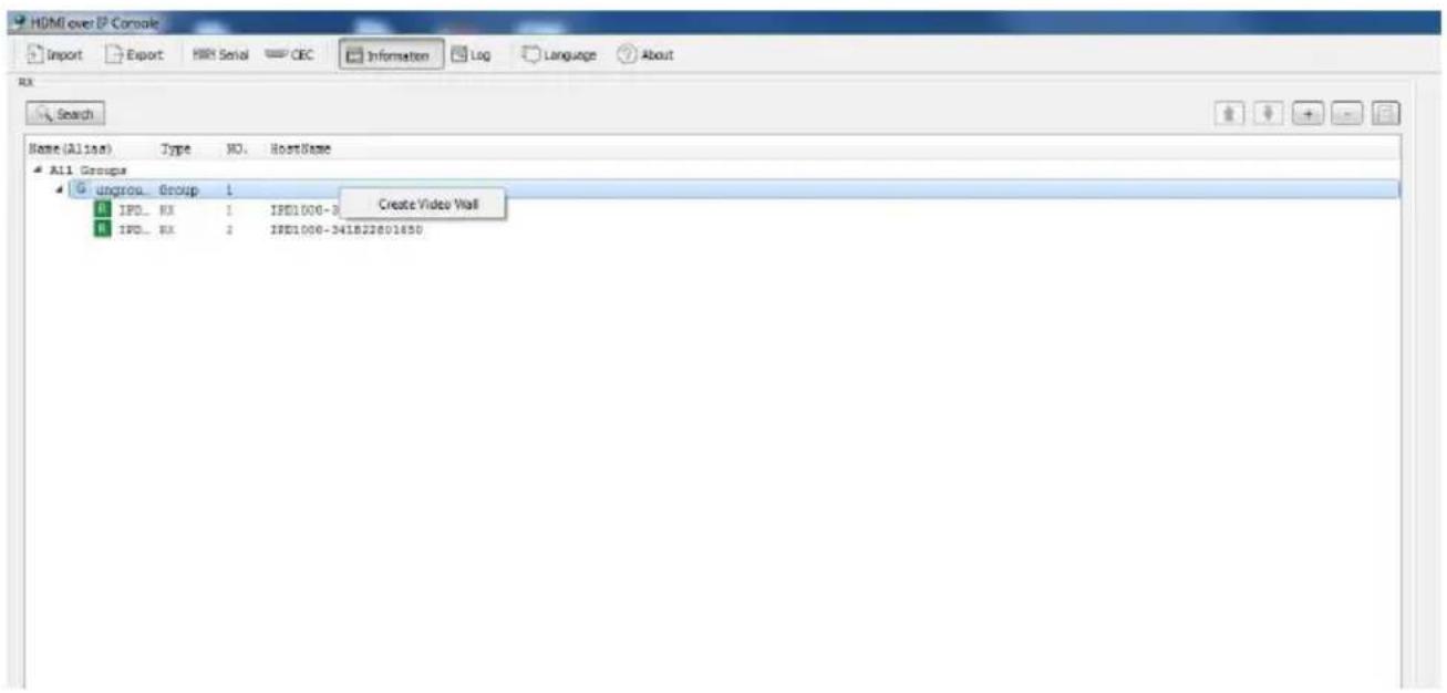
Create a group. To create a group please right click on "ungroup" a create videowall box appears, please click on the tab.
Name: Group 1
Step 3.
In Group 1 create a 2x2 video wall Zone1Scene2 with two rows and two columns.

CREATE AND CONFIGURE VIDEOWALL
Step 4.
In the middle section, click on Create layout button, a window will appear to create "Layout Name".
(1) Please type Matrix.
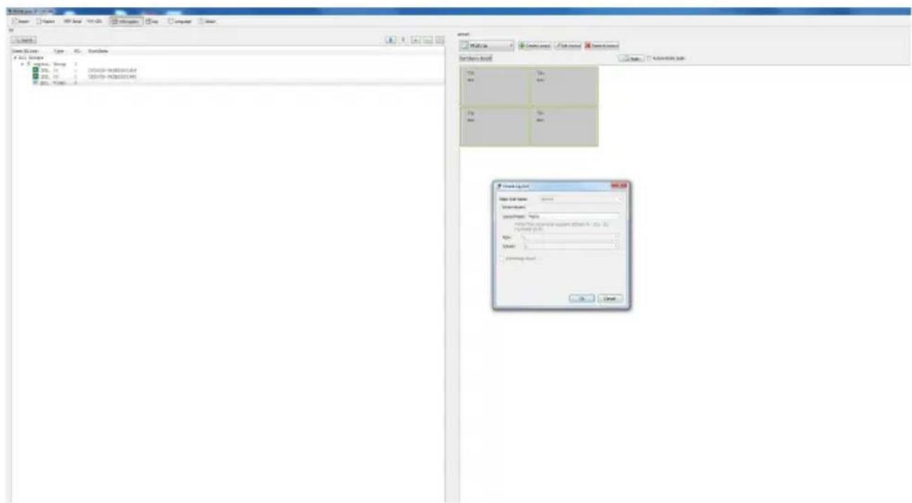
(2) To link/enable video and audio in the matrix, please Drag and Drop the Receiver devices from the left in Group1 to the middle section on the assigned screens. Perform this task again with the Transmitter devices on the right to stream the source to the screens.
NOTES: Apply button must be clicked for the above actions to be activated.

CREATE AND CONFIGURE VIDEOWALL
Step 5.
Create layout B which contains 2x2 combination screen.
(1) In video wall Zone1Scene2, create a layout 2x2.
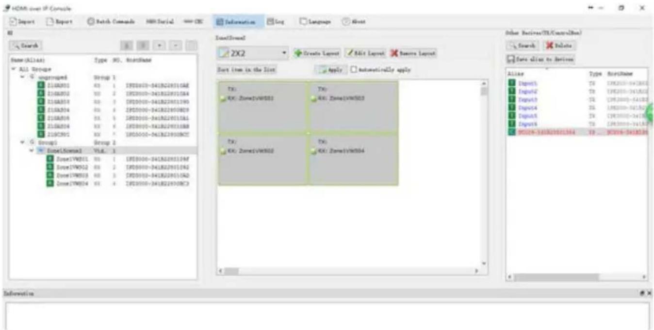
(2) Select the four screens by right clicking on the screen on the upper left corner and moving the cursor while holding the right mouse until all four screens are highlighted.
In the displayed context menu, choose Combine.

CREATE AND CONFIGURE VIDEOWALL
(3) In the Video Wall Properties dialog box, set the combination screen name to vw and click OK.
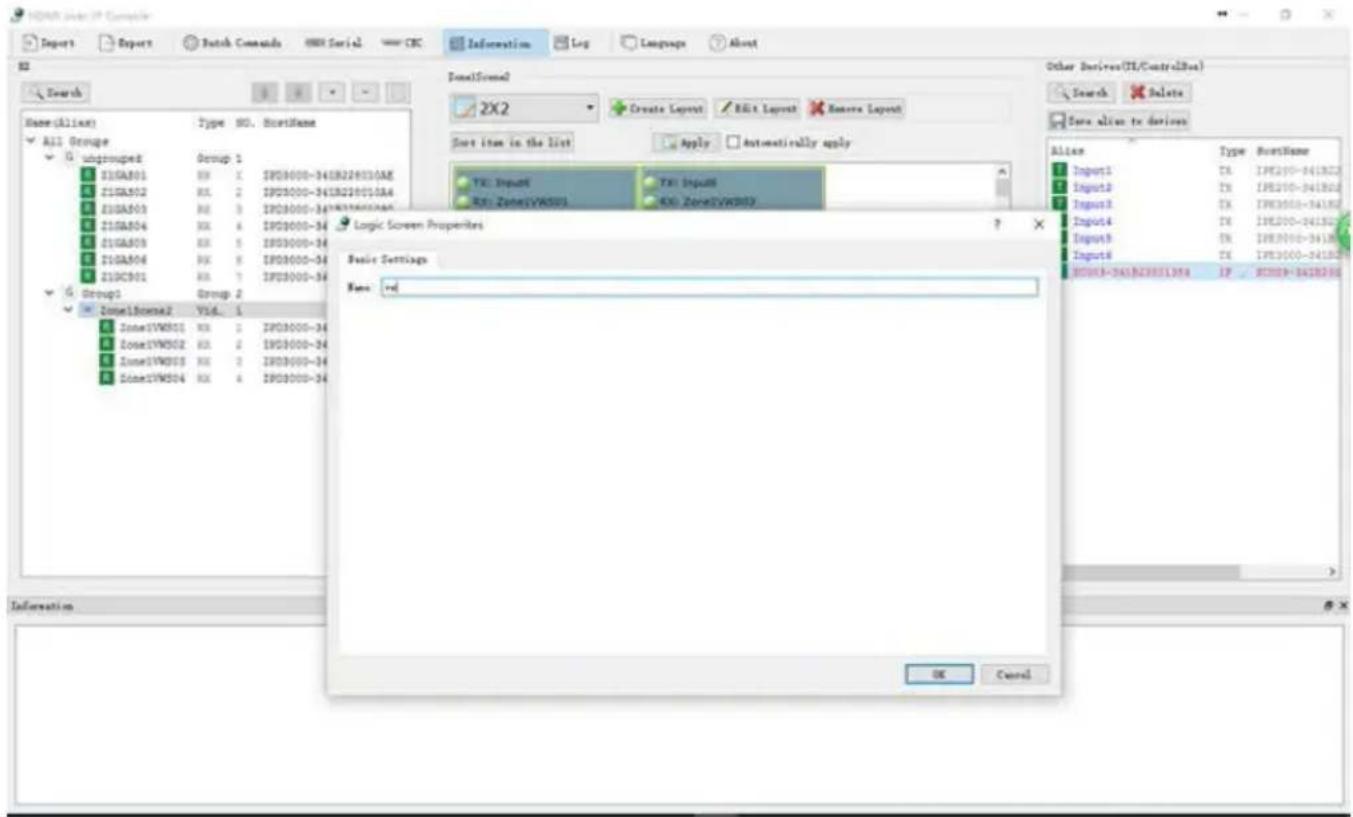
(4) The yellow checkered lines combining the 4 screens indicates a videowall has been created, as shown in the caption below.

CREATE AND CONFIGURE VIDEOWALL
Please Note:
When the video wall and its layouts are completed as the above examples, different layouts can be viewed by clicking on the drop down arrow.
Layout name: Matrix
Content: Four single screens
Location: videowall Zone1Scene2


Layout name: 2x2
Content: 2x2 combination screen vw (configurable)
Location: video wall Zone1Scene2
![HDMI User IP Console Report Report Patch Commands HMI Serial CRC Deformation Log Language About M Search Name(All): Type M0, NextName All-Orange G unbranded Group 1 210A001 00 1 1950000-3418229110A8 210A002 00 2 1950000-3418228910A6 210A003 00 3 1950000-3418228710B6 210A004 00 4 1950000-3418228510B3 210A005 00 5 1950000-3418228310A1 210A006 00 6 1950000-3418228110A9 210C001 00 7 1950000-341822800B7 G Strong Group 2 Box1Box2 Yid 1 Box17W5D1 00 1 1950000-3418228110A9 Box17W5D2 00 2 1950000-3418228910A6 Box17W5D3 00 3 1950000-3418228710A3 Box17W5D4 00 4 1950000-3418228510B3 LocalForm2 ZX2 Create Layout Edit Format Return Layout Next item in the list Apply automatically apply TX: Input6 TX: Input8 RX: Zone1VW5D1 RX: Zone1VW5D3 TX: Input6 TX: Input8 RX: Zone1VW5D2 RX: Zone1VW5D4 Other Devices(CTL/ControlBox) Search Delete Down alias to devices Allie: Type NextName Input1 TX: [FX2D]X-3418D2 Input2 TX: [FX2D]X-3418D2 Input3 TX: [FX3D]X-3418D2 Input4 TX: [FX3D]X-3418D2 Input5 TX: [FX3D]X-3418D2 Input6 TX: [FX3D]X-3418D2 WLSD-34-X3D(D)X: TX: X(D)-74-BL3D](/content/2026/06/1189544/images/c5bf0f4b3220f58c16702fc43240a8e165641338d98190152b4479e92542e4a6.jpg)
CREATE AND CONFIGURE VIDEOWALL
Step 6.
Proceed to upload all the configurations made to the IP controller.
Right click on HVWCTRL (IP controller) in Other Devices area and choose Upload.
When 100% is displayed, the upload is successful.

All steps for creating a videowall and matrix layouts are now successfully completed.
In the above examples, a video wall Zone1Scene2 contains the following two layouts.
- Matrix which contains no combination screen
- 2X2 which contains a combination screen vw and is recognized as Zone1Scene2-2X2_vw in IP controller.
Within the IP controller WEB GUI, the user can input API commands to switch between sources on the video wall.
- To switch between sources for a video wall layout, use vw change vwnname txname.
- To switch between sources for a single screen in a layout, use vw change rxname txname.
Example, to switch to source input1 for the 2X2 videowall screen use vw change Zone1Scene2-2X2_vw Input1.
NOTES:
Naming Convention-Layout and video wall names can only contain numbers 0 to 9, lowercase letters a to z and uppercase letters A to Z.
- To switch between sources for a videowall and a single screen in a layout, use vw change.
- To switch between sources for a single screen outside a layout, use matrix set.
IPAD APP SETUP
HWWCTRL iPad App Quick Start
This guide demonstrates the seamless switching control application for the HVWCIP-Series devices on PC or iPad for small or medium applications where a 3rd Party controller and programmer is not in the budget.
A. HVWCTRL software on iPad
1.1 Key Features
Some of the key features of the HVWCTRL are: The ability to Drag and Drop sources directly to the connected displays, live preview on iPad App of the connected sources, seamless Matrix and Video wall switching, and upload scenes from PC software to HVWCTRL for easy setup and configuration.
1.2 Downloading HVWCTRL-iPad & PC Software
* Search VisualM25 in Apple store and download it.
1.3 Operating HVWCTRL-iPad & PC Software
i. Launching HVWCTRL- iPad & PC Software
HVWCTRL- iPad & PC Software automatically connects to HVWCTRL using the default IP address 169.254.1.1 on its first startup. When connection succeeds, HVWCTRL- iPad & PC Software downloads configuration information from HVWCTRL such as logo icon, group information (includes group name and group sequence), device information (includes device name, groups and device sequence in a group) and video wall information (includes video wall name, layouts, groups and video wall sequence in a group). For iPad to receive /view live video feed from the connected Encoders, must be on the same IP range.
ii. Introduction to HVWCTRL- iPad & PC Software Interface
IPAD APP SETUP
1. Main Screen

When HVWCTRL-iPad & PC Software has established network connection to the HVWCTRL-iPad & PC App controller, the main screen above is displayed.
(1) Logo icon: indicates the image of this app name HVWCTRL- iPad & PC Software, which is uploaded to HVWCTRL- iPad & PC software IP configuration web from your local computer and then is downloaded from HVWCTRL- iPad & PC software IP to HVWCTRL- iPad & PC Software.
(2) Connected and Disconnected: indicates the connection status between HVWCTRL-iPad & PC Software and HVWCTRL-iPad & PC software IP.
(3) System Settings button: used to configure the system settings.
(4) Slider: go to previous or next screen.
(5) To all screen: dragging and dropping a source from source list over this button means the switching of this source to the screens in all groups, including single screens and video walls.
(6) Display On: Power on the displays in all groups (must be compatible with CEC commands).
Display Off: Place all displays in standby state (must be compatible with CEC commands).
IPAD APP SETUP
- Introduction to Video Wall
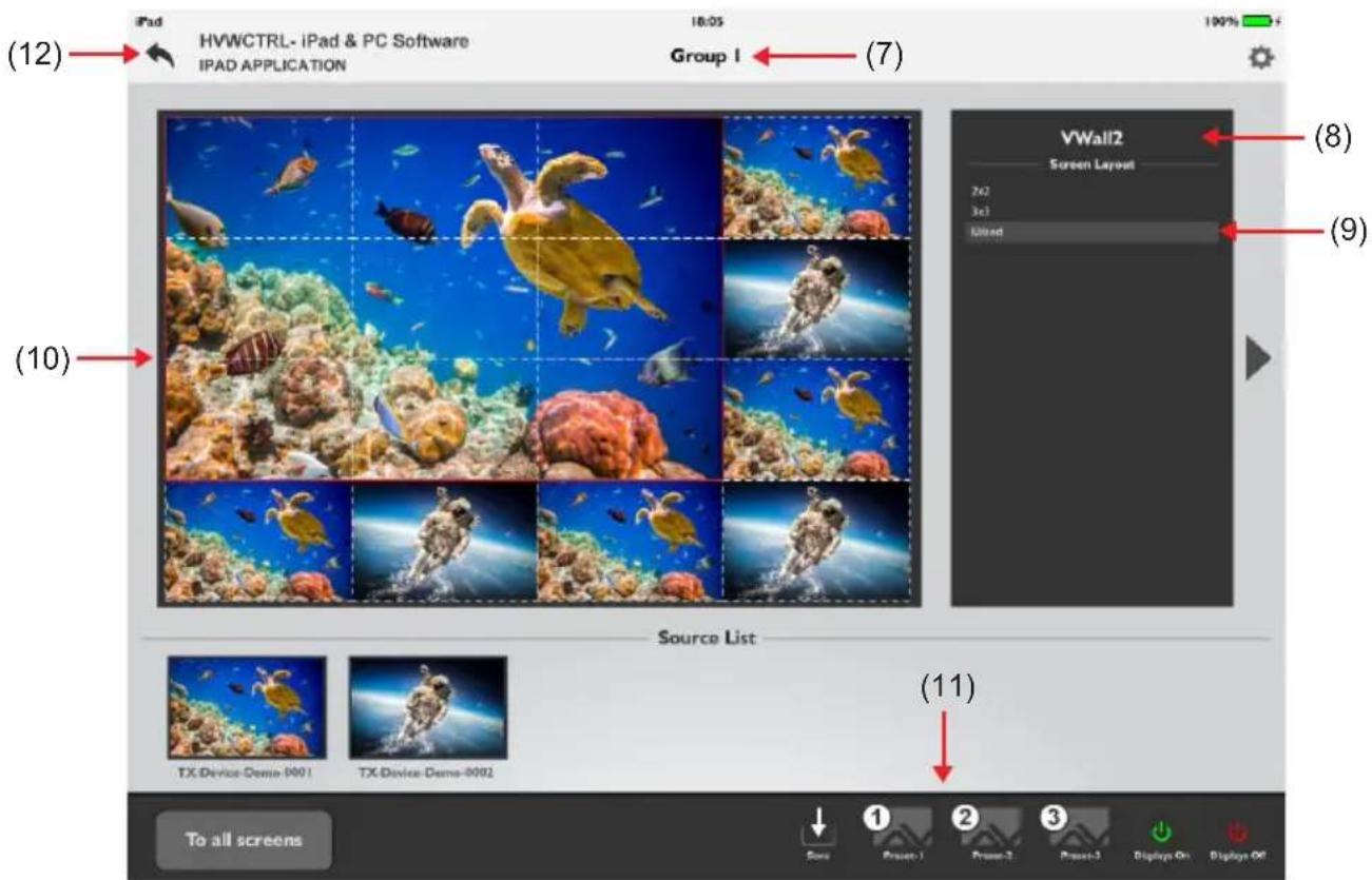
On the main screen, select a group icon to access this group.
If this group is configured for a video wall, the following app interface will show as the above caption.
(7) Group1: indicates the user is in/selected the current group.
(8) VWall2: indicates the video wall name.
(9) Screen layout list: indicate all videowall layouts created, Press a layout to seamlessly switch between each other.
(10) Display area: Drag and drop a video source from the source list to this area to switch between video sources and enjoy live preview as well.
(11) Preset settings:
Save: The current link or configuration made between Receiver and Transmitter in a group as a preset option.
Preset-1, Preset-2 and Preset-3: recall the corresponding relationship between Receiver and Transmitter in a group.
(12) Back button: To navigate to the main screen.
ADVANCE SETTING TABS
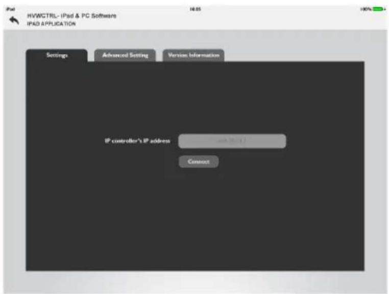

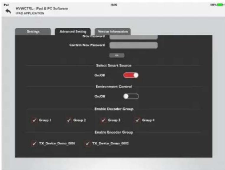
ADVANCE SETTING TABS
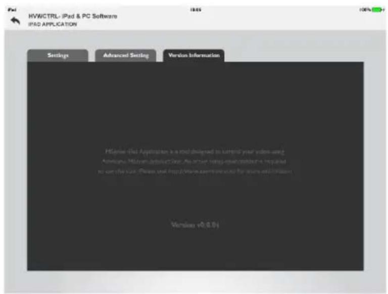
Introduction to System settings Screen
In system settings screen the user can:
- Change HVWCTRL-iPad & PC Software IP address.
- Change advanced setting password (the default is admin).
- Show and hide Receiver groups and Transmitter.
- Enable and disable smart source selection function. When switching between video wall layouts, the video source from the last layout will be used in the current layout.
- Enable and disable environment control function. By default, it's disabled.
- View software version.
SIMPLE API COMMANDS
No. COMMANDS DESCRIPTION
| 1 | Matrix set Transmitter1 / Receiver2/ Receiver3 | Switch between sources for single screens. |
| 2 Vw change Receiver/Transmitter | Switch between sources for single screens.NOTES: For a display in a combination screen, matrix set will not change its video wall status while vw change will set it to exit the current video wall status and to full-screen display of Transmitter. | |
| 3 Vw change vw-name Transmitter Switch between sources for a videowall layout. | ||
| 4 Scene active scenename Switch between video wall layouts. | ||
| 5 | Config set device CEC standby hostname1 hostname2... | Set displays connected to hostname1 and hostname2 to enter standby mode. The displays must support CEC. |
| 6 | Config set device CEC onetouchplay hostname1 hostname2... | Power on displays connected to hostname1 and hostname2. The displays must support CEC. |
- HVWCTRL IP Controller
- TABLE OF CONTENTS
- Contents
- Chapter 1: APP GUIDE FOR THE HVWCIP-SERIES DEVICES....2
- Chapter 2: OVERVIEW....3
- Chapter 3: BEFORE INSTALLATION....4
- Chapter 4: NETWORK BANDWIDTH CALCULATOR....5
- Chapter 5: VIDEO WALL SETUP....7
- Chapter 6: CREATE AND CONFIGURE VIDEOWALL....8
- Chapter 7: IPAD APP SETUP....15
- Chapter 8: ADVANCE SETTING TABS....18
- Chapter 9: SIMPLE API COMMANDS....20
- APP GUIDE FOR THE HVWCIP-SERIES DEVICES
- ABOUT THIS DOCUMENT
- GENERAL INSTRUCTIONS
- OVERVIEW
- BEFORE INSTALLATION
- NETWORK BANDWIDTH CALCULATOR
- Parameters:
- Calculating Transmitter Bandwidth
- HVWCIP-Series iPad Application
- VIDEO WALL SETUP
- Before Starting iPad Control Software
- What is the HVWCTRL?
- Recommended Software Versions:
- CREATE AND CONFIGURE VIDEOWALL
- Step 1.
- Step 2.
- Name: Group 1
- Step 3.
- Step 4.
- Step 5.
- Please Note:
- Step 6.
- All steps for creating a videowall and matrix layouts are now successfully completed.
- NOTES:
- IPAD APP SETUP
- HWWCTRL iPad App Quick Start
- HVWCTRL software on iPad
- Key Features
- Downloading HVWCTRL-iPad & PC Software
- Operating HVWCTRL-iPad & PC Software
- Main Screen
- ADVANCE SETTING TABS
- Introduction to System settings Screen
- SIMPLE API COMMANDS
Brand : AG Neovo
Model : HVWCTRL
Category : Controller