
WorkFit-DL 48 - Desk Stand Ergotron - Free user manual and instructions
Find the device manual for free WorkFit-DL 48 Ergotron in PDF.


| Product Type | Sit-Stand Desk |
| Model | WorkFit-DL 48 |
| Brand | Ergotron |
| Worksurface Size | 48" x 29" (122 x 74 cm) |
| Weight Capacity (48" x 29") | ≤ 50 lbs (22.7 kg) including cable tray |
| Height Travel Range | 20" (508 mm) |
| Brake Type | Hand brake on right leg |
| Stop Screws | Pre-installed for shipping; must be removed before use |
| Adjustment Tool | 14 mm socket drill or wrench |
| Cable Management | Includes cable channel and clips |
| Assembly Required | Yes, two people needed to lift |
| Safety Features | Anti-tipping, crush/impact warnings, stop screws |
| Warranty | Visit www.ergotron.com/warranty |
| Customer Service | 1-800-888-8458 (US) or contact.ergotron.com |
| Recommended Usage | Indoor office environment |
Frequently Asked Questions - WorkFit-DL 48 Ergotron
User questions about WorkFit-DL 48 Ergotron
0 question about this device. Answer the ones you know or ask your own.
Ask a new question about this device
Download the instructions for your Desk Stand in PDF format for free! Find your manual WorkFit-DL 48 - Ergotron and take your electronic device back in hand. On this page are published all the documents necessary for the use of your device. WorkFit-DL 48 by Ergotron.
USER MANUAL WorkFit-DL 48 Ergotron
Total Weight Capacity(includes Cable Tray):
Worksurface size
60"x29"(152x74cm):≤42 lbs.(19.1 kg)
48"x29"(122x74cm):≤50 lbs.(22.7kg)
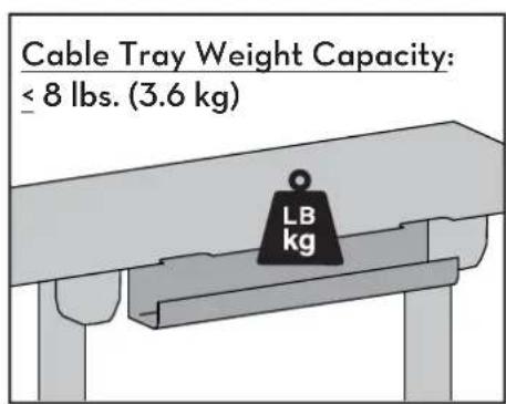

CAUTION: DO NOT EXCEED
User's Guide - English
Hazard Symbols Review
These symbols alert users of a safety condition that demands attention. All users should be able to recognize and understand the significance of the following Safety Hazards if encountered on the product or within the documentation. Children who are not able to recognize and respond appropriately to Safety Alerts should not use this product without adult supervision!
| Symbol | Signal Word | Level of Hazard |
 | NOTE | A NOTE indicates important information that helps you make better use of this product. |
 | CAUTION | A CAUTION indicates either potential damage to hardware or loss of data and tells you how to avoid the problem. |
 | WARNING | A WARNING indicates either potential for property damage, personal injury, or death. |
 | ELECTRICAL | An Electrical indicates an impending electrical hazard which, if not avoided, may result in personal injury, fire and/or death. |
Safety

Important! You will need to adjust this product after installation is complete. Make sure all your equipment is properly installed on the product before attempting adjustments. This product should move smoothly and easily through the full range of motion and stay where you set it. If movements are too easy or difficult or if product does not stay in desired positions, follow the adjustment instructions to create smooth and easy movements. Depending on your product and the adjustment, it may take many turns to notice a difference. Any time equipment is added or removed from this product, resulting in a change in the weight of the mounted load, you should repeat these adjustment steps to ensure safe and optimum operation.
!WARNING
IMPACT HAZARD


Moving Parts Can Crush And Cut
Minimize Lift Strength BEFORE:
- Removing Mounted Equipment and
Insert 4 Stop Screws BEFORE:
- Shipping or Storing (i.e. when Desk is not upright).
To Minimize Lift Strength
Refer to installation manual for instructions on how to minimize lift strength.
To Insert 4 Stop Screws
Refer to installation manual for instructions on installing stop screws.
Failure to heed this warning may result in serious personal injury or property damage!
For More information and instructions visit www.ergotron.com or contact Ergotron Customer Care at 1-800-888-8458.
826-901-00
Safety

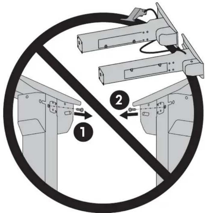
WARNING! Stop screws are pre-installed in this product to secure it in the compressed position during shipping and installation. DO NOT REMOVE THESE SCREWS UNTIL INSTRUCTED TO DO SO IN THESE INSTRUCTIONS. Make sure these screws are in place before starting installation. Failure to follow these instructions may cause lift engine to expand rapidly and may result in equipment damage and or personal injury. If any of the 4 stop screws are not installed in these locations, contact customer care before continuing with installation.
IMPORTANT!
Save these stop screws and instructions. Install stop screws when shipping or storing this product. Failure to follow these instructions may cause lift engine to expand rapidly and may result in equipment damage and or personal injury.
DO NOT REMOVE SCREWS!

WARNING!
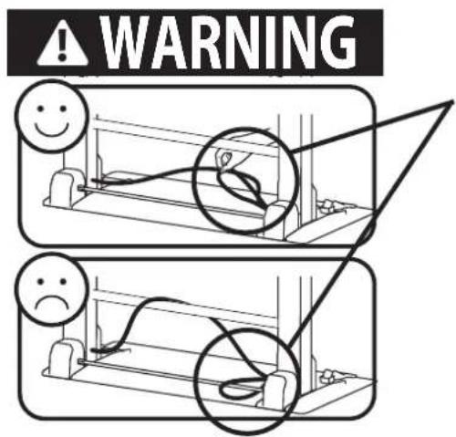
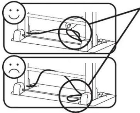
Keep Brake Cables Away from Sync Rod and Crossbars During Installation! Failure to keep the brake cables away from sync rod and crossbars may restrict lift motion and may cause equipment damage or personal injury! Refer to instruction manual for more information.

WARNING! TIPPING HAZARD!
When mounting accessories to the WorkFit-D, they must stay within the foot print. Do not mount accessories past the front and rear worksurface! Failure to follow this warning may result in equipment damage and or personal injury.

Components

1

NOTE: The brake cable is attached to both legs. Take care when removing the legs from the packaging to avoid damaging or pulling the brake cable from the legs.
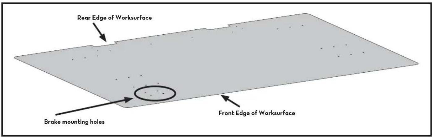
Place the worksurface on a clean floor with the top side facing down.
Carefully position the leg with the hand brake on the side of the worksurface with the brake mounting holes, and the other leg on the other side of the worksurface.

2
Att ach cable channel.

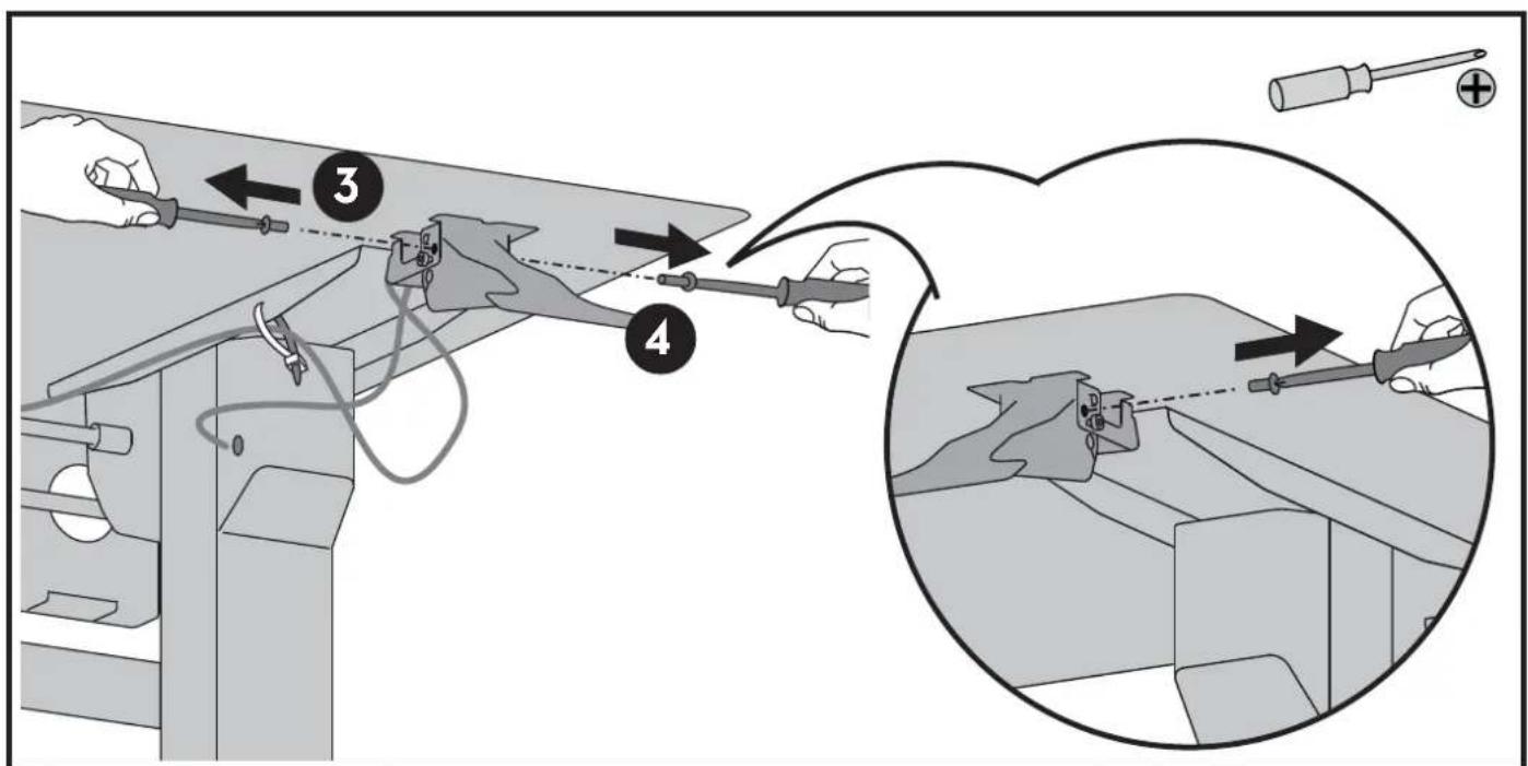
3 Loosely attach the leg with the brake handle to the worksurface.

NOTE: Do not fully insert the screws into the worksurface at this time. Leave approximately 1/8" space.

WARNING

WARNING!
Keep Brake Cables Away from Sync Rod and Crossbars During Installation! Failure to keep the brake cables away from sync rod and crossbars may restrict lift motion and may cause equipment damage or personal injury! Refer to instruction manual for more information.

5
Place the other leg on the worksurface and att ach the sync rod to it.
WARNING
WARNING!
Keep Brake Cables Away from Sync Rod and Crossbars During Installation! Failure to keep the brake cables away from sync rod and crossbars may restrict lift motion and may cause equipment damage or personal injury! Refer to instruction manual for more information.
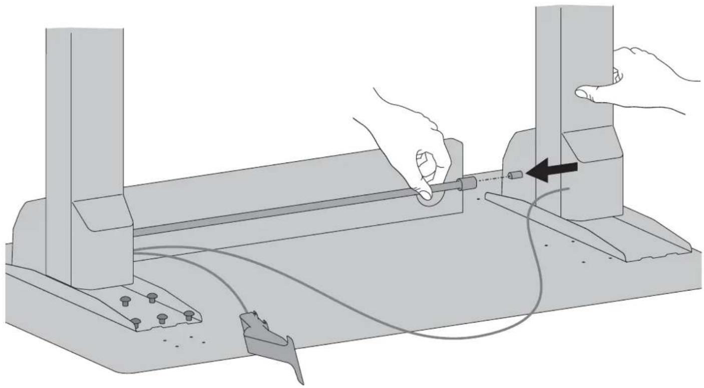

NOTE: Do not fully insert the screws into the worksurface at this time. Leave approximately 1/8" space.

7
Att ach crossbar. Make sure the brake cables don't loop around the crossbars.
Tighten the screws slightly one at a time and repeat to ensure that the tension on every screw is equal.

NOTE: Do not overtighten screws. overtightening screws may result in stripping the holes and may cause the installation to be unsafe.


10
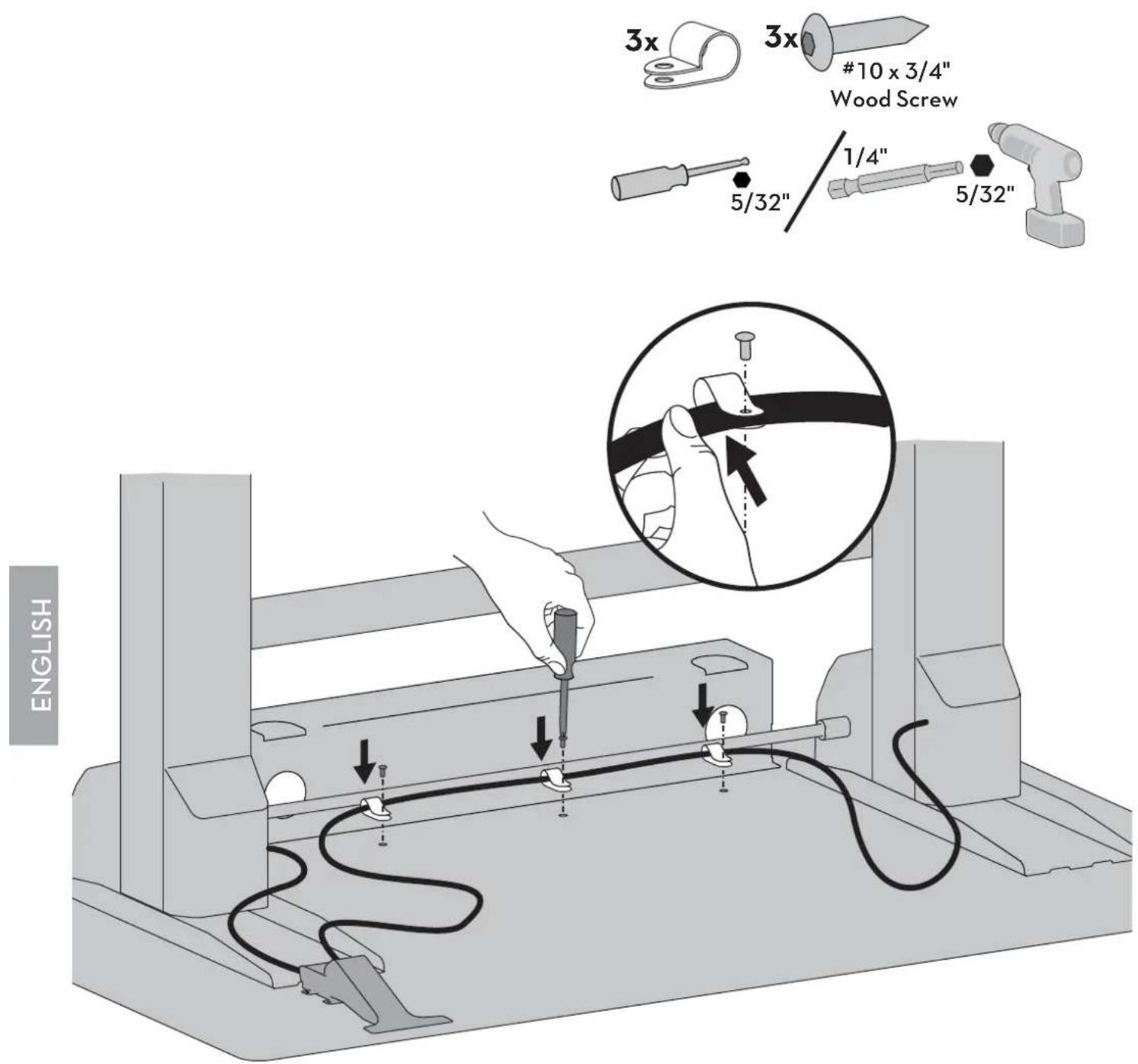
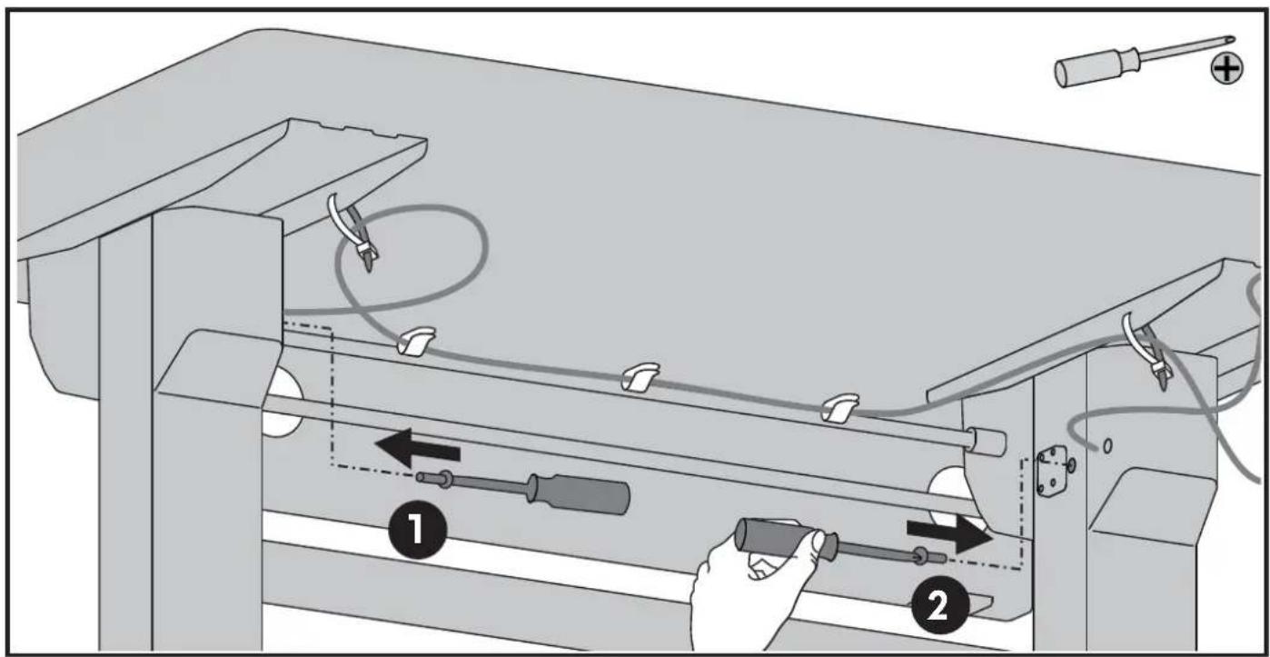
Insert brake cable into 3 cable clips and attach to worksurface.
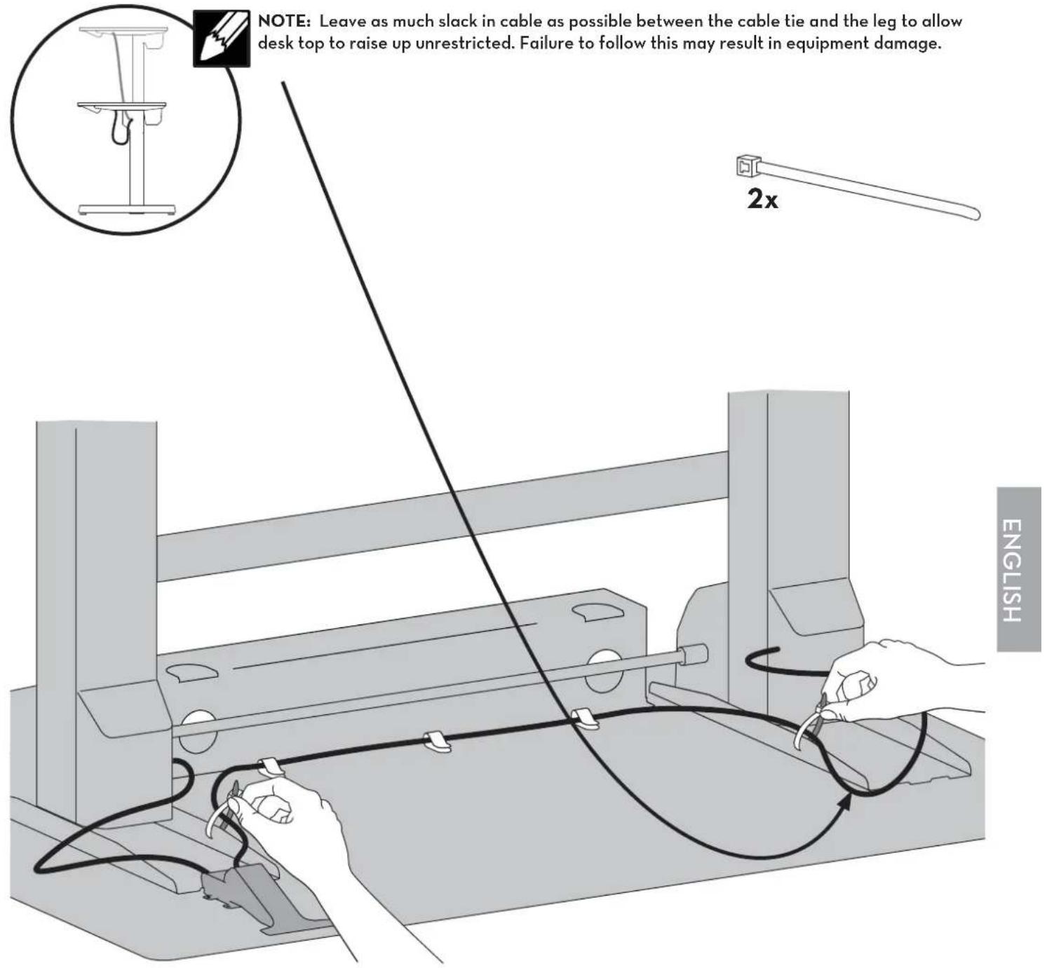

NOTE: Leave as little slack in cable as possible between this cable tie and the brake release lever.
12

b

C
8x

13
Set the desk upright onto its legs.


CAUTION!
LIFT HAZARD!
Two persons are required for this step. Failure to follow this warning may result in equipment damage and or personal injury.
a

b

14
Remove the 4 brake stop screws before installing equipment.
Remove the 2 stop screws from the legs then the 2 stop screws from the brake to allow the worksurface to raise and lower.
IMPORTANT!
Save these stop screws and instructions. Install stop screws when shipping or storing this product. Failure to follow these instructions may cause lift engine to expand rapidly and may result in equipment damage and or personal injury.

15
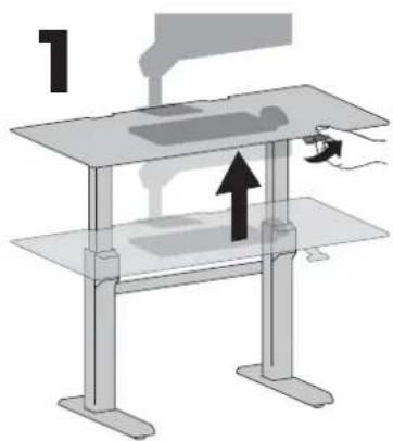
After you remove the 4 brake stop screws, release the hand brake (on the right leg) and move the worksurface up to highest level.

16
Install all equipment.

CAUTION! Make sure you leave 20" (508mm) of slack in all equipment cables to allow the worksurface to raise up it's full 20" (508mm). Failure to allow enough slack in equipment cables may cause cables to get pulled, equipment to fall off desk and may result in product damage and or personal injury.

17
Adjustment Step
Important! You will need to adjust this product after installation is complete. Make sure all your equipment is properly installed on the product before attempting adjustments. This product should move smoothly and easily through the full range of motion and stay where you set it. If movements are too easy or difficult or if product does not stay in desired positions, follow the adjustment instructions to create smooth and easy movements. Depending on your product and the adjustment, it may take many turns to notice a difference. Any time equipment is added or removed from this product, resulting in a change in the weight of the mounted load, you should repeat these adjustment steps to ensure safe and optimum operation.

Test Lift strength by raising and lowering desk. If it is too easy or too difficult to lift/lower, then follow the next set of adjustment steps to properly counterbalance the lift strength with the weight of the mounted equipment.


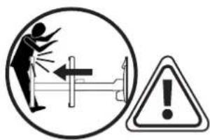
WARNING! DO NOT tip desk over to adjust. Only perform adjustment while desk is upright. Failure to follow these instructions may cause the lift engine to expand rapidly and may result in equipment damage and or personal injury.

First you will need to raise the desk all the way to the highest position. Release brake and lift up.

Adjustment Step

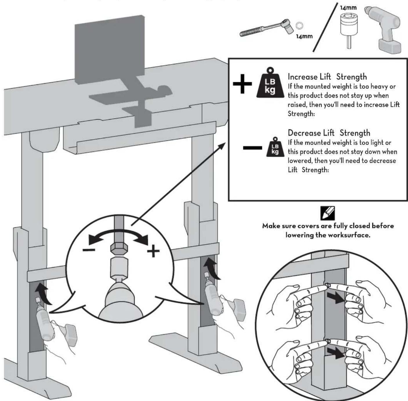
On the back of each leg, push in the adjustment doors to access the adjustment bolts.

NOTE: The covers on the legs will not open unless the worksurface has been lifted to it's full height. The worksurface will not lower unless the covers have been completely closed.


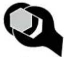
Use either a socket drill or a socket wrench to adjust the bolts. A socket drill is recommended due to the adjustment bolts needing many turns before noticing a difference in lift strength. Make sure you are adjusting the lift strength for both legs equally.

Adjust the riser on each leg and check with a level to make sure the work surface is even.

Your Installation is Complete
The following steps are for shipping or storing your cart.
APPENDIX A - Minimize Lift Tension

WARNING. Before removing mounted equipment (monitor, arm, stand CPU, etc.), from desk, or to prepare for shipping or storing the desk it is extremely important to minimize the lift tension. Failure to follow these instructions may cause lift engine to expand rapidly and may result in equipment damage and or personal injury.

WARNING! DO NOT tip desk over to adjust. Only perform adjustment while desk is upright. Failure to follow these instructions may cause the lift engine to expand rapidly and may result in equipment damage and or personal injury.
- Release the hand brake (on the right leg) and move the worksurface up to highest level.
- Push in the cover located behind each leg to access the adjustment point.

NOTE: The covers on the legs will not open unless the worksurface has been lifted to it's full height. The worksurface will not lower unless the covers have been completely closed.
2


- To minimize tension, turn adjustment bolts left using a 14mm socket drill. Maintain equal tension on both legs by alternating adjustment from one leg to the other. Keep adjusting until the wrench stops turning.
- Once at minimum tension it is ok to remove mounted equipment.

Make sure covers are fully closed before lowering the worksurface.

APPENDIX B - Inserting Stop Screws

WARNING. Before shipping or storing the desk, or in cases where the desk is placed on it's back or side*, it is extremely important that the 4 stop screws be re-inserted. Failure to follow these instructions may cause lift engine to expand rapidly and may result in equipment damage and or personal injury.
- Follow instructions in Appendix A to minimize lift tension.
- Push the desk down to its lowest position.
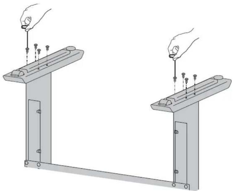
- Insert 2 stop screws at the bottom of each leg.
- Insert the other 2 stop screws on each side of the hand brake located on the right side of the worksurface.
- Once the 4 stop screws have been installed the desk can be shipped or stored.
* Placing the desk on its back or side is not recommended.


Learn more about ergonomic computer use at: www.computingcomfort.org
Height
Position top of screen slightly below eye level.
Position keyboard at about elbow height with wrists fl at.
Distance
Position screen an arm's length from face—at least 20" (508mm).
Position keyboard close enough to create a 90° angle in elbow.
Angle
Tilt screen to eliminate glare.
Tilt the keyboard back 10° so that your wrists remain fl at.
To Reduce Fatigue
Breathe - Breathe deeply through your nose.
Blink - Blink oft en to avoid dry eyes.
Break · 2 to 3 minutes every 20 minutes
• 15 to 20 minutes every 2 hours.
For Warranty visit: www.ergotron.com/warranty
For Service visit: www.ergotron.com
For local customer care phone numbers visit: http://contact.ergotron.com

NOTE: When contacting customer service, reference the serial number.

Americas Sales and
Corporate Headquarters
EMEA Sales
1181 Trapp Rd.
St. Paul, MN USA
(800) 888-8458
+1-651-681-7600
www.ergotron.com
sales@ergotron.com
Amersfoort, The Netherlands
+31 33 45 45 600
www.ergotron.com
info.eu@ergotron.com
APAC Sales
Tokyo, Japan
www.ergotron.com
apaccustomerservice@ergotron.com
Worldwide OEM Sales
www.ergotron.com
info.oem@ergotron.com
ERGOTRON®
While Ergotron, Inc. makes every effort to provide accurate and complete information on the installation and use of its products, it will not be held liable for any editorial errors or omissions (including those made in the process of translation from English to another language), or for incidental special or consequential damages of any nature resulting from furnishing this instruction and performance of equipment in connection with this instruction. Ergotron, Inc. reserves the right to make changes in the product design and/or product documentation without notification to its users. For the most current product information, or to know if this document is available in languages other than those herein, please contact Ergotron. No part of this publication may be reproduced, stored in a retrieval system, or transmitted in any form or by any means, electronic, mechanical, photocopying, recording or otherwise without the prior written consent of Ergotron, Inc.,1181 Trapp Road, Eagan, Minnesota, SS121, USA Patents Pending and Patented U.S. & Foreign. Ergotron is a registered trademark of Ergotron, Inc.
© 2016 Ergotron, Inc. All rights reserved.


- HAZARD SYMBOLS REVIEW
- SAFETY
- WARNING
- IMPACT HAZARD
- MOVING PARTS CAN CRUSH AND CUT
- IMPORTANT
- WARNING! TIPPING HAZARD
- COMPONENTS
- 1
- 3 LOOSELY ATTACH THE LEG WITH THE BRAKE HANDLE TO THE WORKSURFACE
- 5
- 7
- 10
- 13
- CAUTION
- LIFT HAZARD
- 14
- 15
- 16
- 17
- ADJUSTMENT STEP
- YOUR INSTALLATION IS COMPLETE
- APPENDIX A - MINIMIZE LIFT TENSION
- APPENDIX B - INSERTING STOP SCREWS
- ERGOTRON®
Brand : Ergotron
Model : WorkFit-DL 48
Category : Desk Stand