97-854 - Medical accessory Ergotron - Free user manual and instructions
Find the device manual for free 97-854 Ergotron in PDF.

User questions about 97-854 Ergotron
0 question about this device. Answer the ones you know or ask your own.
Ask a new question about this device
Download the instructions for your Medical accessory in PDF format for free! Find your manual 97-854 - Ergotron and take your electronic device back in hand. On this page are published all the documents necessary for the use of your device. 97-854 by Ergotron.
USER MANUAL 97-854 Ergotron
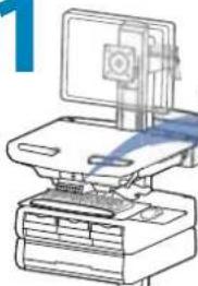
StyleView® Telemedicine Bin

www.ergotron.com

USA 1-800-888-8458
Europe +31 (0)33-45 45 600
China 86-769-86018920
For service and warranty visit www.ergotron.com
User's Guide - English
natural_image
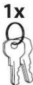
Simple line drawing of a rectangular frame with four vertical lines and a wavy top edge (no text or symbols)1x
2x
M4 x 12mm
D
1x
1x
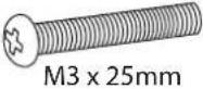
M3 x 25mm

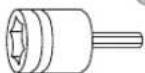
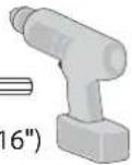
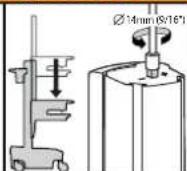
14mm (9/16")

natural_image
Simple line drawing of a vertical mechanical device inside a circle (no text or symbols)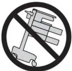
text_image
Prohibition sign with crossed-out robot and battery symbols, indicating no use or prohibition
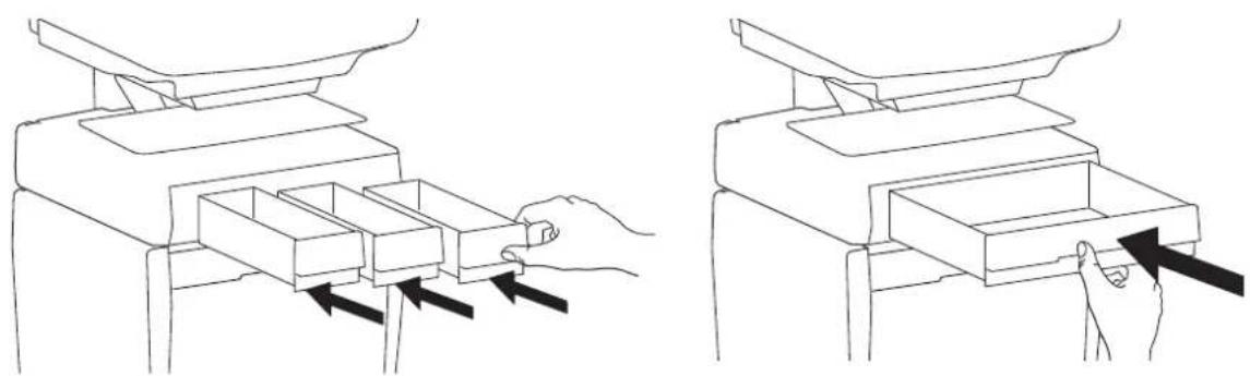
CAUTION: Close worksurface before opening drawers. Open only one drawer at a time. Do Not push cart when drawers or worksurface are open. Failure to follow these instructions may cause the cart to be unstable.

WARNING

IMPACT HAZARD!
MOVING PARTS CAN CRUSH AND CUT.
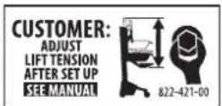
Minimize Lift Tension BEFORE:
- Removing Mounted Equipment.
- Shipping Cart
- Storing Cart
To Minimize Lift Tension
- Lower worksurface to lowest position.
- Turn adjustment nut at top of riser
counterclockwise until it stops
(Adjustment may require 40-60 revolutions).
Failure to heed this warning may result in
serious personal injury or property damage!
For More information and instructions refer to product
guide at http://4support.ergotron.com or contact
Ergotron Customer Care at 1-800-888-8458.
822-052

natural_image
Illustration of a hand holding a cable or wire inserted into a ceiling structure (no text or symbols)
NOTE: When removing drawers from the cart, make sure to disconnect the cable.

text_image
12.8" (324 mm) 10.7" (272 mm) 5.3" (134 mm) 5.4" (138 mm) Top View 12" (308 mm) 13" (329 mm) 11" (280 mm) 15.6" (395 mm) 12.6"-24.4" (320-620 mm) Front View Side View1
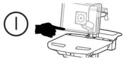
a
Turn off all mounted equipment.
text_image
Diagram showing a hand pointing at a device with a numbered circle nearby, likely indicating a step or instruction.b
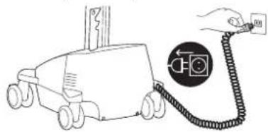
Disconnect Power System from power source.
text_image
Diagram showing a vehicle connected to a car with a hand holding a cable, featuring a camera icon and directional arrows.C
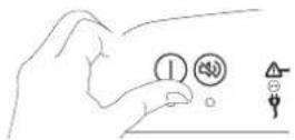
Turn power system off by holding down the AC Outlet Power button for 1 - 3 seconds. Power light will shut off.
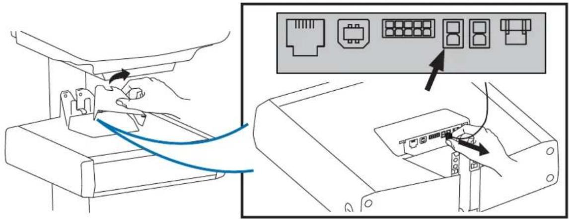
d
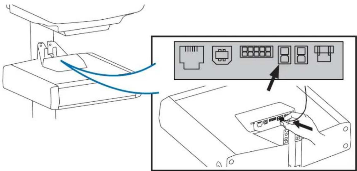
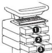
Disconnect Power from Drawer.
text_image
Diagram showing connection between a device and its internal components, with labeled ports and arrows indicating connection paths.2
Attach the Travel Stop bracket to the lift engine to keep the drawer from hitting the base.
1x
natural_image
Line drawing of a hand using a handheld device to press down a small mechanical component (no text or symbols)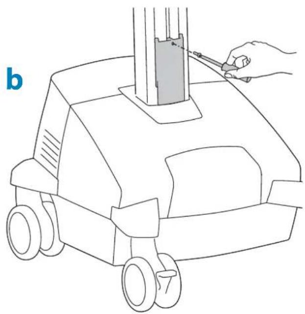
natural_image
Line drawing of a hand using a tool to press or install a mechanical component, no text or symbols present3
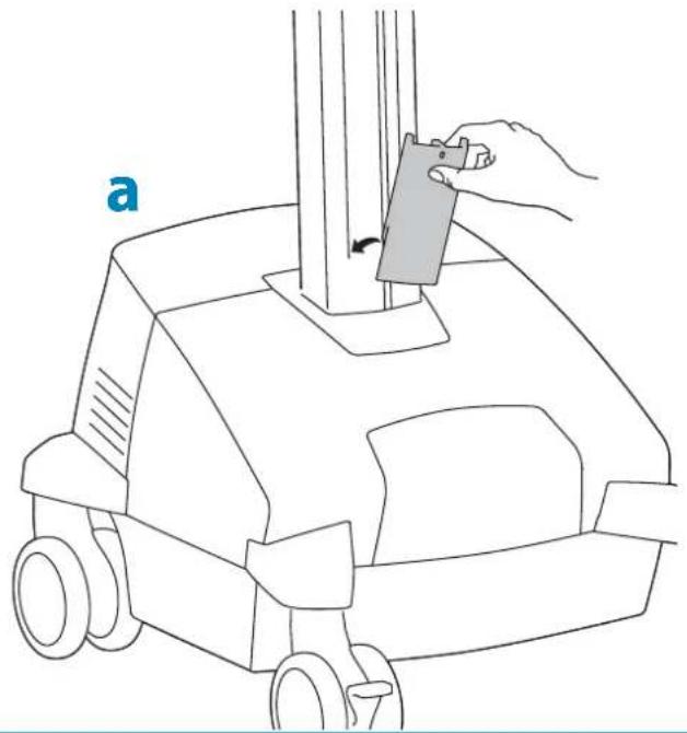
Remove plug cover.

natural_image
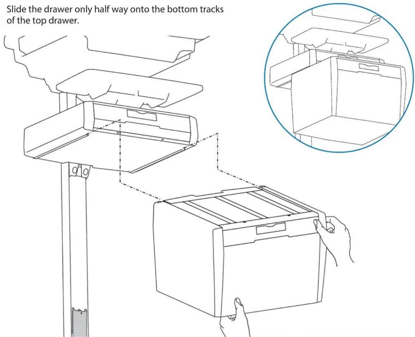
Line drawing of a hand using a screwdriver to adjust or install a device component (no text or symbols present)4 Slide the drawer only half way onto the bottom tracks of the top drawer.
text_image
Slide the drawer only half way onto the bottom tracks of the top drawer.5 a Plug the cable on the bottom drawer into the jack on the bottom of the drawer above it.
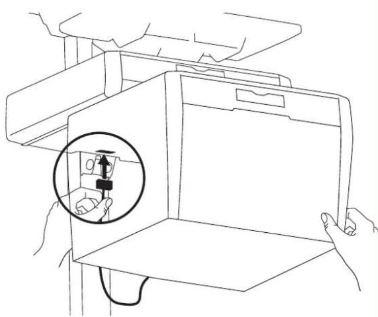
natural_image
Line drawing of a person inside a box with hands holding a device, showing a magnified inset of the device (no text or symbols present)b Slide the drawer completely onto the bottom tracks of the top drawer.
natural_image
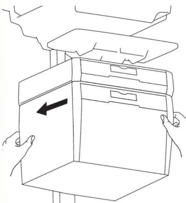
Line drawing of two hands opening a cardboard box with an arrow indicating left motion (no text or symbols)6
Remove the top drawer(s).
natural_image
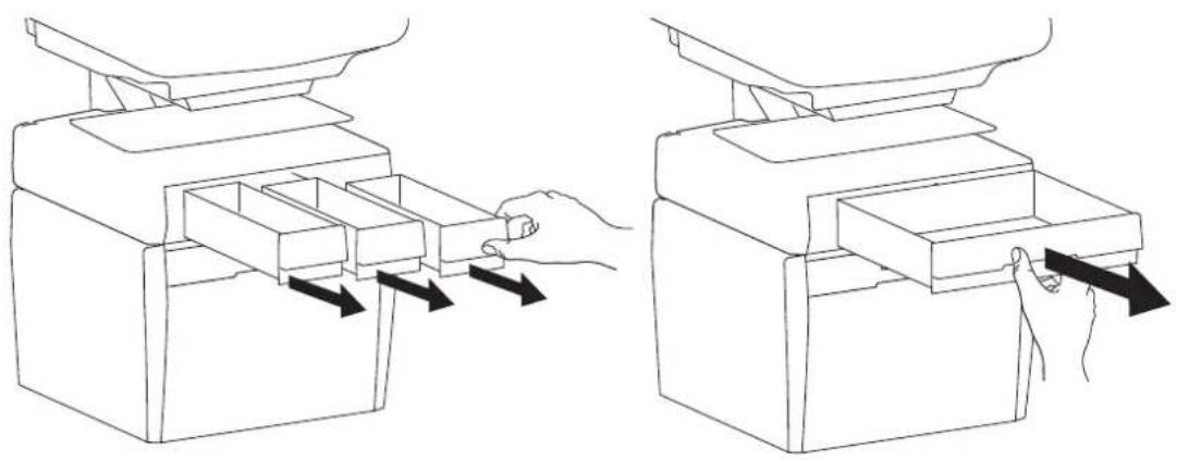
Line drawing showing two steps of a device with arrows indicating process flow (no text or symbols)7
Secure the bottom drawer by attaching the two screws.

natural_image
Line drawing of a hand using a pipette to press down an open printer (no text or symbols present)2x
M4×12mm
8
Replace the top drawer(s).
natural_image
Line drawings of a hand inserting objects into a device, showing two different states of mechanical assembly (no text or symbols)

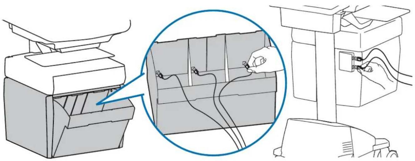
Reconnect drawer power.
text_image
Diagram showing connection between a device and its internal network ports, with an inset highlighting the port layout.
Replace top cover on drawer.

natural_image
Line drawing of a hand using a tool to press or install a device into a rectangular box (no text or symbols)
natural_image
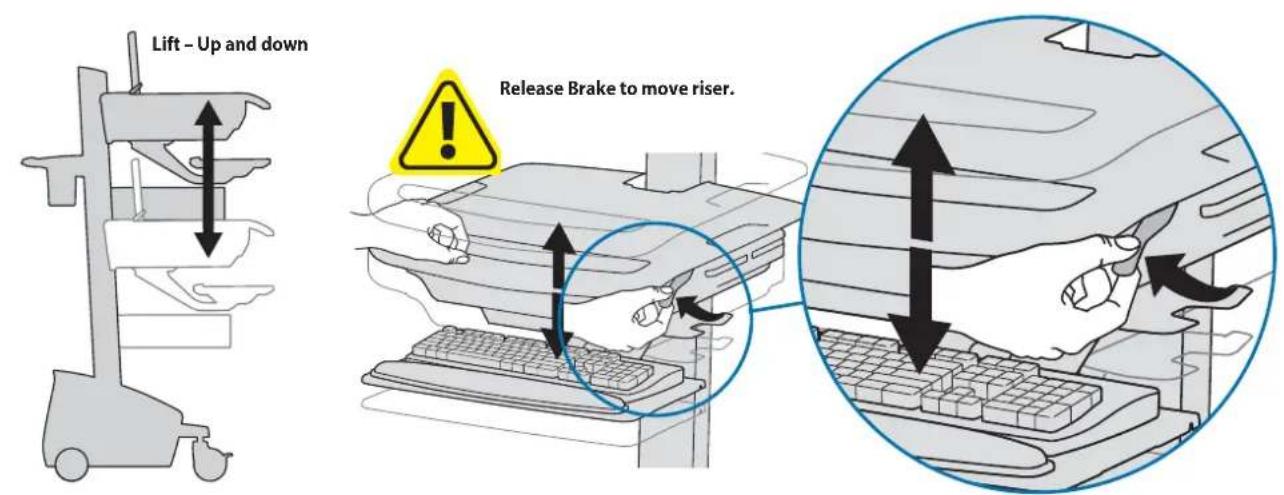
Line drawing of a hand holding a tool over a device with a directional arrow (no text or symbols)10 Adjustment
It is important that you adjust this product according to the weight of the mounted equipment as described in the following steps. Any time equipment is added or removed from this product, resulting in a change in the weight of the mounted load, you should repeat these adjustment steps to ensure safe and optimum operation.
Adjustments should move smoothly and easily through the full range of motion and stay where you set it. If adjustments are difficult and do not stay in the desired position, follow the instructions to loosen or tighten the tension to create a smooth, easy adjustment motion. Depending on your product and the adjustment, it may take several turns to notice a difference.
text_image
Lift - Up and down Release Brake to move riser.
text_image
Follow these instructions to tighten or loosen tension. 14mm (9/16") NOTE: Adjustment may require 40 - 60 revolutions.11
natural_image
Line drawing of a printer with a paper airplane and a monitor, no text or symbols presentNOTE: User should change Master Personal Identifi cation Number (PIN) upon receipt of cart.
Ensure that the main power system batteries are installed and functioning. The power does not need to be turned on at the power system user interface.

User PINs:
Without StyleLink management:
- PINs entered on the cart and not managed by StyleLink may vary in length from 4-7 digits.
- Ergotron recommends the following for choosing PIN digit length (assumes less than 1 in 25 chance of guessing random User PIN):
Max number of User PINs >50, 5+digit length recommended
Max number of User PINs >300, 6+digit length recommended
For maximum security use PIN length of 7
- Carts store up to 1,000 PINs.
With StyleLink management:
- Maximum 100 PINs per cart.
- 5 digit PIN length required.


CAUTION: Open only one drawer at a time. Do Not push cart when drawers are open. Failure to follow these instructions may cause the cart to be unstable.
Set-up Master PIN for the First Time (Default Master PIN: 12345)
Contact Ergotron Customer Care for instructions if Master PIN is lost.
-
Enter default Master PIN (1-2-3-4-5) then press ENTER.
-
Press 5 for Master PIN Entry mode
-
Enter new Master PIN and press Enter (LEDs will blink green if PIN is accepted)
-
Master PIN entry mode will exit after 5 seconds of inactivity (LEDs blink red twice)
Master PIN Mode Menu (NOTE: Master PIN does not open drawers.)
Enter Master PIN and then select one of the below numbers to enter that mode
-
After entering Master PIN, Select 1 to access User PIN Entry Mode
-
After entering Master PIN, Select 2 to access Pharmacy PIN Entry/Change Mode
-
After entering Master PIN, Select 5 to access Master Pin Change Mode
Master PIN Mode Menu (continued)
6, 1. After entering master PIN, select 6 then select 1 to mute alarm.
6, 6, Master PIN, Enter. After entering master PIN, select 6 then select 6 again, then enter Master PIN again, then select Enter. This will reset keypad to the factory default Master PIN as 1, 2, 3, 4, 5, and will also delete all personal PINs and Pharmacy PIN.
Programming User PINS
-
Enter Master PIN and press ENTER for Mode Menu.
-
Press 1 for User PIN Entry Mode.
-
Input new User PIN and press ENTER (All LEDs blink green if PIN is accepted). You may enter multiple USER PINs consecutively.
-
User PIN entry mode will exit after 5 seconds of inactivity (LEDs blink red twice).
NOTE: User PIN cannot be the same as a Master PIN or Pharmacy PIN. Once maximum User PIN storage is exceeded, the oldest User PIN will be over written.
Programming Pharmacy PIN
-
Enter Master PIN and press ENTER for Mode Menu
-
Press 2 for Pharmacy PIN Entry Mode
-
Input Pharmacy PIN and press ENTER (all LEDs blink green in PIN is accepted).
-
Pharmacy PIN entry mode will exit after 5 seconds of inactivity (LEDs blink red twice).
Note: System will hold 1 Pharmacy PIN. Pharmacy PIN allows all drawers to unlock at the same time. Drawers should then be opened at least slightly as the system will auto-lock after 15 seconds. All LEDs will flash green until system auto-locks. Once a drawer is opened the corresponding LED for that row will light solid until it is placed back into its original location.
If drawers are removed from cart for filling, they must be replaced in the same configuration per row. If they are not, power must be removed and reapplied so that the drawer system reconfi gures itself.
Unlock Drawer (2 methods): NOTE: All Drawers in row must be closed before a new row can be unlocked.
- Enter User PIN (only numbers for available drawer rows flash green), then press desired drawer row number*.
• Key - turn clockwise 1/4 turn
*Drawer Row Numbers:

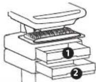
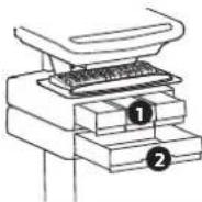

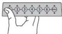

text_image
Diagram illustrating a key inserted into a computer with an open lock, showing key and lock mechanism.Lock Drawer:
- Wait 4 seconds for lock to engage automatically.
NOTE: Always ensure drawer is pushed in all the way and engaged with lock.
Drawer Troubleshooting
• No LEDs on keypad when pressing any number:
- Verify DC cable is connected from cart battery harness to controller.
- Verify keypad cable is connected to controller.
- Verify circuit breakers are not tripped and 5A fuse is installed in battery harness.
- Drawer selection not available when User PIN is entered:
- Check to make sure drawer cable is installed securely.
- Remove power from drawer system for 10 seconds and re-apply.
• LEDs flash red/green after User PIN in entered:
- Battery charge is low, check to make sure USB charging cable is plugged into computer and computer is ON.
LEDs/Alarm Meaning:
1,2,3,4, or 5 LED ON green: Corresponding Drawer is open.
1,2,3,4, or 5 LED fl ashing red and alarm sounding: Corresponding Drawer is open longer than 20 seconds. Mute alarm by pressing fl ashing button corresponding to open drawer.
All available drawer numbers flashing green: Waiting for drawer selection (see Unlock Drawer).
All LEDs blink red twice: PIN entry rejected/exit current mode after 5 seconds timeout.
All LEDs blink green 3 times: PIN entry accepted.
All LEDs flashing red: Firmware update in progress.
All LEDs flashing red/green: System power ON or low battery condition.
12
Telemedicine Bin - includes dividers, 3 USB ports inside and 2 USB ports on back of drawer. 6' max USB cable length for stored devices.
natural_image
Illustration of a printer being connected to a circuit board, showing internal wiring and connection (no text or symbols)
While Ergotron, Inc. makes every effort to provide accurate and complete information on the installation and use of its products, it will not be held liable for any editorial errors or omissions (including those made in the process of translation from English to another language), or for incidental, special or consequential damages of any nature resulting from furnishing this instruction and performance of equipment in connection with this instruction. Ergotron, Inc. reserves the right to make changes in the product design and/or product documentation without notification to its users. For the most current product information, or to know if this document is available in languages other than those herein, please contact Ergotron. No part of this publication may be reproduced, stored in a retrieval system, or transmitted in any form or by any means, electronic, mechanical, photocopying, recording or otherwise without the prior written consent of Ergotron, Inc., 1181 Trapp Road, Eagan, Minnesota, 55121, USA Patents Pending and Patented U.S. & Foreign. Ergotron is a registered trademark of Ergotron, Inc.
Americas Sales and
Corporate Headquarters
EMEA Sales
St. Paul, MN USA
(800) 888-8458
+1-651-681-7600
www.ergotron.com
sales@ergotron.com
Amersfoort, The Netherlands
+31 33 45 45 600
www.ergotron.com
info.eu@ergotron.com
APAC Sales
Tokyo, Japan
www.ergotron.com
apaccustomerservice@ergotron.com
Worldwide OEM Sales
www.ergotron.com
info.oem@ergotron.com