REJCPTZ-1 - Contrôleur de clavier REVO - Free user manual and instructions
Find the device manual for free REJCPTZ-1 REVO in PDF.

| Product Type | Keyboard Controller |
| Brand | REVO |
| Model | REJCPTZ-1 |
| Dimensions (W x D x H) | 150 x 100 x 30 mm |
| Weight | 200 g |
| Power Supply | USB 5V or DC 5V adapter (not included) |
| Connection Interface | USB Type-C |
| Compatible Systems | Windows, macOS, Linux |
| Key Switches Supported | MX-style mechanical switches |
| Maximum Keys | 108 keys (full-size matrix) |
| Programmable Layers | Up to 8 |
| Macro Support | Yes, per-key and global macros |
| Backlight Control | RGB per-key, 16.8 million colors |
| Polling Rate | 1000 Hz |
| Maintenance | Keep dry; clean with soft, dry cloth |
| Safety Precautions | Do not expose to liquids or excessive heat |
| Spare Parts / Repairability | Not user-serviceable; contact support |
| General Information | Designed for custom keyboard enthusiasts |
Frequently Asked Questions - REJCPTZ-1 REVO
User questions about REJCPTZ-1 REVO
0 question about this device. Answer the ones you know or ask your own.
Ask a new question about this device
Download the instructions for your Contrôleur de clavier in PDF format for free! Find your manual REJCPTZ-1 - REVO and take your electronic device back in hand. On this page are published all the documents necessary for the use of your device. REJCPTZ-1 by REVO.
USER MANUAL REJCPTZ-1 REVO
natural_image
Black and white industrial control console with rotary knob and keyboard (no visible text or symbols)WARNING AND CAUTION
WARNING
TO REDUCE THE RISK OF FIRE OR ELECTRIC SHOCK, DO NOT EXPOSE THIS PRODUCT TO RAIN OR MOISTURE. DO NOT INSERT ANY METALLIC OBJECTS THROUGH THE VENTILATION GRILLS OR OTHER OPENINGS ON THE EQUIPMENT.
CAUTION

text_image
CAUTION RISK OF ELECTRIC SHOCK DO NOT OPEN CAUTION: TO REDUCE THE RISK OF ELECTRIC SHOCK, DO NOT REMOVE COVER(OR BACK). NO USER-SERVICEABLE PARTS INSIDE. REFER SERVICING TO QUALIFIED SERVICE PERSONNEL.EXPLANATION OF GRAPHICAL SYMBOLS
The lightning flash with arrowhead symbol, within an equilateral triangle, is intended to alert the user to the presence of uninsulated "dangerous voltage" within the product's enclosure that may be of sufficient magnitude to constitute a risk of electric shock to persons.

The exclamation point within an equilateral triangle is intended to alert the user to the presence of important operating and maintenance (servicing) instruction in the literature accompanying the product.
FCC COMPLIANCE STATEMENT
FCC INFORMATION: THIS EQUIPMENT HAS BEEN TESTED AND FOUND TO COMPLY WITH THE LIMITS FOR A CLASS A DIGITAL DEVICE, PURSUANT TO PART 15 OF THE FCC RULES. THESE LIMITS ARE DESIGNED TO PROVIDE REASONABLE PROTECTION AGAINST HARMFUL INTERFERENCE WHEN THE EQUIPMENT IS OPERATED IN A COMMERCIAL ENVIRONMENT. THIS EQUIPMENT GENERATES, USES, AND CAN RADIATE RADIO FREQUENCY ENERGY AND IF NOT INSTALLED AND USED IN ACCORDANCE WITH THE INSTRUCTION MANUAL, MAY CAUSE HARMFUL INTERFERENCE TO RADIO COMMUNICATIONS. OPERATION OF THIS EQUIPMENT IN A RESIDENTIAL AREA IS LIKELY TO CAUSE HARMFUL INTERFERENCE IN WHICH CASE THE USER WILL BE REQUIRED TO CORRECT THE INTERFERENCE AT HIS OWN EXPENSE.
CAUTION: CHANGES OR MODIFICATIONS NOT EXPRESSLY APPROVED BY THE PARTY RESPONSIBLE FOR COMPLIANCE COULD VOID THE USER'S AUTHORITY TO OPERATE THE EQUIPMENT.
THIS CLASS A DIGITAL APPARATUS COMPLIES WITH CANADIAN ICES-003. CET APPAREIL NUMÉRIQUE DE LA CLASSE A EST CONFORME À LA NORME NMB-003 DU CANADA.
CE COMPLIANCE STATEMENT
WARNING
THIS IS A CLASS A PRODUCT. IN A DOMESTIC ENVIRONMENT THIS PRODUCT MAY CAUSE RADIO INTERFERENCE IN WHICH CASE THE USER MAY BE REQUIRED TO TAKE ADEQUATE MEASURES.
IMPORTANT SAFEGUARDS
- Read these instructions.
- Keep these instructions.
- Heed all warnings.
- Follow all instructions.
- Do not use this apparatus near water.
-
Clean only with dry cloth.
-
Do not block any ventilation openings. Install in accordance with the manufacturer's instructions.
-
Do not install near any heat sources such as radiators, heat registers, stoves, or other apparatus (including amplifiers) that product heat.
-
Do not defeat the safety purpose of the polarized or grounding-type plug. A polarized plug has two blades with one wider than the other. A grounding type plug has two blades and a third grounding prong. The wide blade or the third prong is provided for your safety. If the provided plug does not fit into your outlet, consult an electrician for replacement of the obsolete outlet.
-
Protect the power cord from being walked on or pinched particularly at plugs, convenience receptacles, and the point where they exit from the apparatus.
-
Only use attachments/accessories specified by the manufacturer.
-
Unplug this apparatus during lightning storms or when unused for long periods of time.
-
Refer all servicing to qualified service personnel. Servicing is required when the apparatus has been damaged in any way, such as power-supply cord or plug is damaged, liquid has been spilled or objects have fallen into the apparatus, the apparatus has been exposed to rain or moisture, does not operate normally, or has been dropped.
-
CAUTION - THESE SERVICING INSTRUCTIONS ARE FOR USE BY QUALIFIED SERVICE PERSONNEL ONLY. TO REDUCE THE RISK OF ELECTRIC SHOCK DO NOT PERFORM ANY SERVICING OTHER THAN THAT CONTAINED IN THE OPERATING INSTRUCTIONS UNLESS YOU ARE QUALIFIED TO DO SO.
-
Use Certified/Listed Class 2 power supply transformer only.
Table of Contents
| Chapter 1 — Introduction ...... 1 | |
| 1.1 Features ...... 1 | |
| 1.2 Package Contents ...... 2 | |
| 1.3 Required Installation Tools ...... 2 | |
| 1.4 Connectors ...... 2 | |
| Chapter 2 — Installation and Configuration ...... 3 | |
| 2.1 Basic Configuration of Fastrax Dome System...... 3 | |
| 2.2 Configuration with DVR...... 4 | |
| 2.3 Configuration with MUX...... 5 | |
| 2.4 Configuration of Master and Slave Keyboards...... 6 | |
| 2.5 Termination...... 7 | |
| 2.6 Dip Switch Settings...... 10 | |
| 2.7 Multiplexer Configuration...... 10 | |
| Chapter 3 — Keyboard Setup ...... 12 | |
| 3.1 Configuration ...... 12 | |
| Change User Password ...... 12 | |
| Change Administrator Password ...... 13 | |
| 3.2 Network ...... 13 | |
| Set Port ...... 13 | |
| Set Baud Rate ...... 13 | |
| Com Ports ...... 14 | |
| MUX Config (Multiplexer Configuration)...... 14 | |
| Set Slave Kbd ...... 17 | |
| Slave KBD Unit ...... 17 | |
| 3.3 Camera ...... 17 | |
| 3.4 Time / Date ...... 18 | |
| 3.5 ALARM ...... 18 | |
| 3.6 LCD ...... 19 | |
| 3.7 DATA BANK ...... 19 | |
| 3.8 INITIALIZATION ...... 20 | |
| 3.9 HOLD TIME ...... 20 | |
| Chapter 4 — Slave Keyboard Setup ...... 21 | |
| Chapter 5 — Install with DVR Series ...... 22 | |
| 5.1 Install with Standalone DVR Series...... 22 | |
| 5.2 Install with PC DVR Series ...... 24 | |
| Chapter 6 — Operation......27 | |
| 6.1 Keyboard Lock/Unlock (Hidden command)......27 | |
| 6.2 Controlling Multiplexer......27 | |
| 6.2.1 Selecting Multiplexer......27 | |
| 6.2.2 Dome Camera Selection......27 | |
| 6.3 Summary of Keyboard Controls......28 | |
| 6.3.1 Keys for Dome camera......29 | |
| 6.3.2 Keys for Multiplexer......30 | |
| 6.3.3.1 Keys for DVR [DVR1-4, PC-DVR]......31 | |
| 6.3.3.2 Example of Key operation in PC-DVR......33 | |
| 6.4 DVR5 protocol for the DVR for the version 3.1.0 and over......34 | |
| Appendix A- Short Cut Key......39 | |
| Appendix B- Trouble Shooting......41 | |
| Appendix C- OPTIONAL JUNCTION BOX......41 | |
| Appendix D -SPECIFICATION......42 | |
Chapter 1 — Introduction
1.1 Features
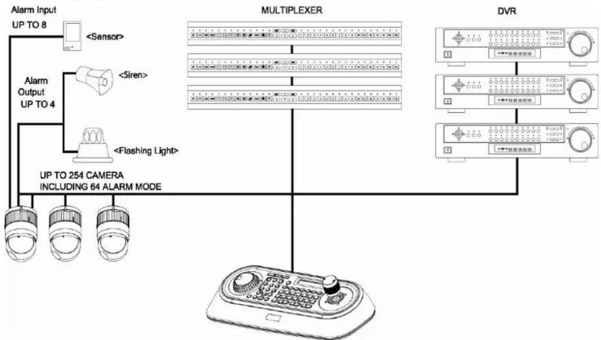
This keyboard controller is capable of controlling dome cameras and providing remote control functions for a variety of external switching devices such as Multiplexers, Digital Video Recorders etc.
A combination of 4 Keyboard controllers and 5 Multiplexers comprises a small matrix system (64x4) using its remote control functions and programmable macro functions.
● Variable speed control joystick with zoom controlling handle.
- Program and recall programmed preset positions, auto scan, tour, pattern, from the selected dome camera.
- Two levels of password are supported for higher security, administrator and user.
● Up to 254 dome cameras controllable including 64 dome cameras with Alarm mode.
- Multiplexers (Max 255) and DVR system (Max 99) can be controlled remotely at each KBD controller regardless Master or Slave.
- Using 3\~5 multiplexers and 4 Keyboard controllers, 32\~64x4 matrix system can be configured.
- Up to 3 slave of the same type keyboard controllers can be connected to the master keyboard.
● Battery backed-up clock displays real time on the LCD screen.
- Up to two dome cameras' programmed data can be downloaded to nonvolatile memory space, and later uploaded to the new dome camera.
● The dome with the ID up to 3999 can be controlled.
- Scan range option: 32, 254, 3999.
flowchart
graph TD
    A["Alarm Input UP TO 8"] --> B["<Sensor>"]
    C["Alarm Output UP TO 4"] --> D["<Siren>"]
    C --> E["<Flashing Light>"]
    F["UP TO 254 CAMERA INCLUDING 64 ALARM MODE"] --> G["MULTIPLEXER"]
    G --> H["DVR"]
    H --> I["+/-按钮开关"]
    H --> J["+/-按钮开关"]
    H --> K["+/-按钮开关"]
Figure 1 – Typical system Configuration
1.2 Package Contents
The package contains the following.
| Description | Q'ty |
| Keyboard controller | 1 |
| Instruction manual | 1 |
| 12VDC Power supply (SMPS) | 1 |
| Power Cord | 1 |
1.3 Required Installation Tools
No special tools are required to install the KBD controller. Refer to the installation manuals for the other items that make up part of your system.
1.4 Connectors
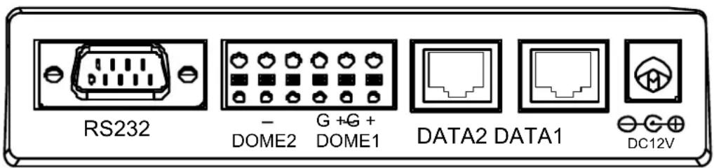
text_image
RS232 - DOME2 G +G + DOME1 DATA2 DATA1 DC12V| CONNECTOR | USAGE |
| RS232 | RS232:DVR/UPGRADE |
| DOME2 | RS485:DOME/DVR/MULTIPLEXER/SLAVE KEYBOARD |
| DOME1 | RS485:DOME |
| DATA2 | FOR JUNCTION BOX ONLY |
| DATA1 | FOR JUNCTION BOX ONLY |
| DC12V | FOR POWER SUPPLY |
NOTE: DON'T CONNECT THE DATA1 PORT AND DC12V PORT TOGETHER.
Chapter 2 — Installation and Configuration
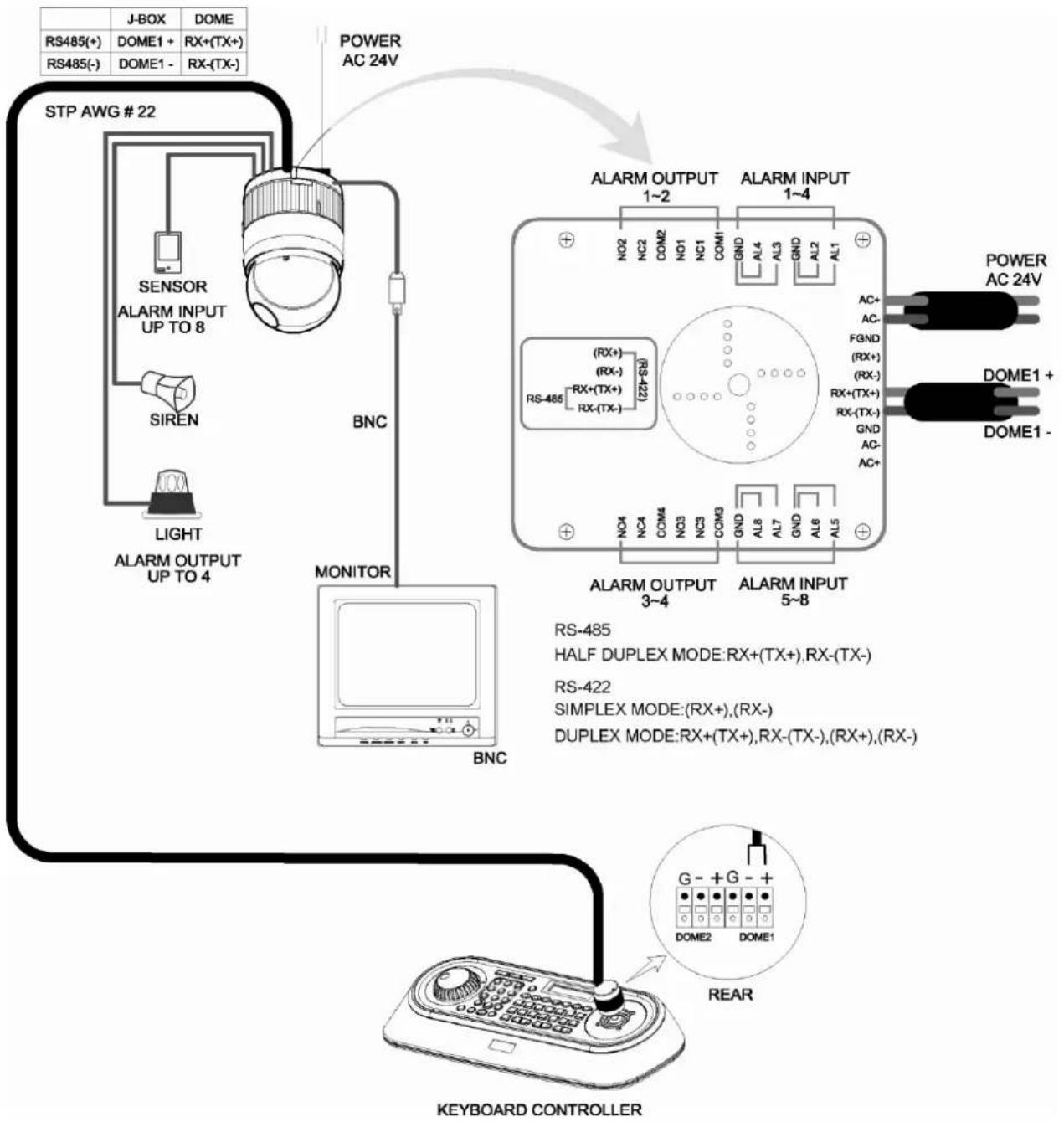
2.1 Basic Configuration of Fastrax Dome System.
flowchart
graph TD
    A["STP AWG # 22"] --> B["Sensor"]
    B --> C["ALARM INPUT UP TO 8"]
    B --> D["SIREN"]
    B --> E["LIGHT"]
    E --> F["ALARM OUTPUT UP TO 4"]
    F --> G["BNC"]
    G --> H["MONITOR"]
    H --> I["BNC"]
    I --> J["KEYBOARD CONTROLLER"]

    K["POWER AC 24V"] --> L["ALARM OUTPUT 1~2"]
    K --> M["ALARM INPUT 1~4"]

    N["ALARM OUTPUT 3~4"] --> O["ALARM INPUT 5~8"]

    P["POWER AC 24V"] --> Q["DOME1 + DOME1 -"]

    R["RS-485"] --> S["HALF DUPLEX MODE: RX+(TX+), RX-(TX-)"]
    T["RS-422"] --> U["SIMPLEX MODE: RX+, (RX-)"]
    V["DUPLEX MODE: RX+(TX+), RX-(TX-), (RX+), (RX-)"]
    W["G- + G- + DOME2 DOME1"] --> X["REAR"]
Figure 2 – Basic installation diagram
2.2 Configuration with DVR.

flowchart
graph TD
    A["STP AWG #22"] --> B["SENSOR ALARM INPUT UP TO 8"]
    A --> C["SIREN"]
    A --> D["LIGHT ALARM OUTPUT UP TO 4"]
    B --> E["BNC"]
    E --> F["POWER AC 24V"]
    F --> G["ALARM OUTPUT 1~2"]
    F --> H["ALARM INPUT 1~4"]
    G --> I["RS-485 (RX+), RX-(TX+)"]
    H --> J["RS-485 (RX-), RX-(TX-)"]
    I --> K["ALARM OUTPUT 3~4"]
    I --> L["ALARM INPUT 5~8"]
    K --> M["MONITOR"]
    L --> N["REAR"]
    M --> O["STANDALONE DVR SERIES"]
    N --> P["DOME1"]
    N --> Q["DOME2"]
    N --> R["KEYBOARD CONTROLLER"]
    G --> S["POWER AC 24V"]
    H --> T["DOME1 + DOME1 -"]
    style A fill:#f9f,stroke:#333
    style F fill:#ccf,stroke:#333
    style G fill:#cfc,stroke:#333
    style H fill:#cfc,stroke:#333
    style I fill:#fcc,stroke:#333
    style J fill:#fcc,stroke:#333
    style K fill:#fcc,stroke:#333
    style L fill:#fcc,stroke:#333
    style M fill:#ffc,stroke:#333
    style N fill:#ffc,stroke:#333
    style O fill:#ffc,stroke:#333
    style P fill:#ffc,stroke:#333
    style Q fill:#ffc,stroke:#333
    style R fill:#ffc,stroke:#333
Figure 3 –installation diagram with DVR
2.3 Configuration with MUX.

flowchart
graph TD
    A["STP AWG # 22"] -->|J-BOX, DOME, RS485(+) / RS485(-)| B["SENSOR ALARM INPUT UP TO 8"]
    A -->|SIREN, LIGHT ALARM OUTPUT UP TO 4| C["BNC"]
    A --> D["ALARM OUTPUT 1~2, ALARM INPUT 1~4"]
    D --> E["RS-485 RX+ (TX+) RX-(TX-) (22V-30)"]
    D --> F["ALARM OUTPUT 3~4, ALARM INPUT 5~8"]
    D --> G["MAIN MONITOR"]
    G --> H["MULTIPLEXER"]
    H --> I["DOME1"]
    H --> J["DOME2"]
    H --> K["KEYBOARD CONTROLLER"]
    D --> L["POWER AC 24V"]
    G --> M["RS-485(+), RS-485(-), RS-485(+), RS-485(-), RS-485(+), RS-485(-), RS-485(-), RS-485(+), RS-485(-), RS-485(-), RS-485(+), RS-485(-), RS-485(-), RS-485(+), RS-485(-), RS-485(-), RS-485(+), RS-485(-), RS-485(-), RS-485(+), RARE"]
    style A fill:#f9f,stroke:#333
    style D fill:#ccf,stroke:#333
    style G fill:#cfc,stroke:#333
    style H fill:#fcc,stroke:#333
    style I fill:#ffc,stroke:#333
    style J fill:#fcc,stroke:#333
    style K fill:#fcc,stroke:#333
Figure 4 –installation diagram with MUX
2.4 Configuration of Master and Slave Keyboards.

flowchart
graph TD
    A["STP AWG #22"] --> B["POWER AC 24V"]
    B --> C["SLAVE K/B CONTROL CONNECTION"]
    C --> D["MASTER KEYBOARD CONTROLLER\nDIP SW 1=ON\nDIP SW 2=ON"]
    C --> E["REAR"]
    C --> F["SLAVE1 KEYBOARD CONTROLLER\nDIP SW 1=OFF"]
    C --> G["REAR"]
    C --> H["SLAVE3 KEYBOARD CONTROLLER\nDIP SW 1=ON"]
    C --> I["REAR"]
    C --> J["SLAVE2 KEYBOARD CONTROLLER\nDIP SW 1=OFF"]
    C --> K["REAR"]
Figure 5 –Master and Slave keyboard connection
Note: Connect the DOME1 port of all slave keyboards to the DOME2 port of the master keyboard and set the DIP SW 1 and 2 as the figure above.
| Without J-BOX | |
| Master Keyboard Setting | Slave Keyboard Setting |
1.  2. 2. 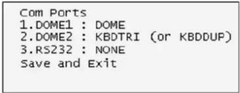 3. 3.  4. 4. 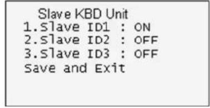 | 1. Dip switch the 8th of S1 is "ON"2. Network1.J-BOX Set: OFF2. Keyboard ID: 013.BPS:9600Save and Exit |
| With J-BOX | |
| Master Keyboard Setting | Slave Keyboard Setting |
1. | 1. Dip switch the 8thof S1 is "ON"2. Network1.J-BOX Set : ON2. Keyboard ID : 013.BPS:9600Save and Exit |
2. | |
3. | |
4. | |
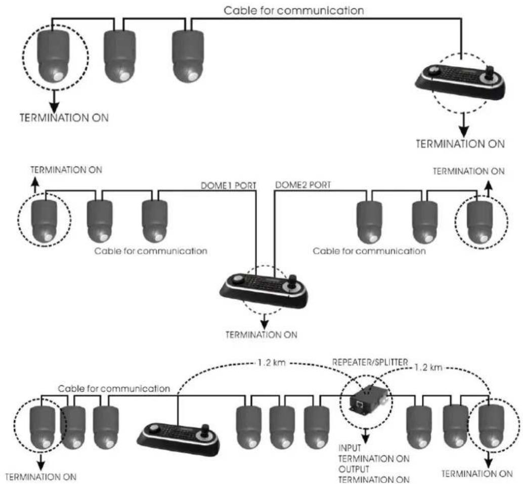
2.5 Termination.
The first and last devices in an installation (dome and keyboard controller) must have the data line terminated by setting the DIP switch. Without proper termination, there is potential for control signal errors. Total length of the cable for communication should not exceed 4000ft (1.2Km). Refer to Figure 6 for setting the dome camera and keyboard controller termination.
flowchart
graph TD
    A["Cable for communication"] --> B["TERMINATION ON"]
    A --> C["DOME1 PORT"]
    A --> D["DOME2 PORT"]
    A --> E["TERMINATION ON"]
    F["Cable for communication"] --> G["Cable for communication"]
    F --> H["DOME1 PORT"]
    F --> I["DOME2 PORT"]
    F --> J["TERMINATION ON"]
    K["REPEATER/SPLITTER"] --> L["INPUT TERMINATION ON OUTPUT TERMINATION ON"]
    K --> M["TERMINATION ON"]
    N["TERMINATION ON"] --> O["Cable for communication"]
    N --> P["1.2 km"]
    N --> Q["1.2 km"]
Figure 6 – Termination
2.6 Dip Switch Settings.
Termination and Master/Slave: Set the switches according to your configuration.

text_image
S1 ON 9J12345678Figure 7 – Keyboard DIP Switches
| NO | SETTING | DESCRIPTION |
| 1 | ON | DOME1 Termination |
| OFF | ||
| 2 | ON | DOME2 Termination |
| OFF | ||
| 3 | ON | J-BOX Data2 Termination |
| OFF | ||
| 4~6 | OFF | Reserved |
| 7 | ON | DOWNLOAD ON |
| OFF | DOWNLOAD OFF | |
| 8 | ON | SLAVE |
| OFF | MASTER |
Table 1 - S1 Switch Setting
2.7 Multiplexer Configuration
Duplex setup:
NOTE: Multiplexers to be controlled by the keyboard controller require a new ROM version. The new multiplexer ROM accepts control instructions from the keyboard controller. If your multiplexer's serial number is M104xxxx or higher, then it is ready to accept control instructions. Alternately, you can check the status of your multiplexer by pressing the Menu key of the multiplexer and then selecting item 9. If you see the “** Protocol” option line in the Communication Setup menu, your multiplexer has the new ROM, and you do not need to replace the ROM. If your multiplexer has the old ROM version, contact your distributor on how to get new a ROM.
CAUTION: Before opening the multiplexer, make certain you are working on an antistatic work surface and that you are wearing a grounding wrist strap. Also, be very careful to orient the ROM chip correctly and not bend any of the pins.
NOTE: Replace the multiplexer firmware with the new multiplexer ROM (U45) as follows; Remove the top cover of the multiplexer, and locate the ROM (U45). Before removing the ROM, note the orientation of the ROM. After removing the old ROM from the socket, insert the new ROM. Be careful to orient the new ROM the same as the old ROM. (Refer to the Multiplexer instruction manual.)
Set the multiplexer functions as follows:
(Press the Menu key of the multiplexer to enter the Unit Options menu.)
9 Unit Options
Unit Number: 001 (first Mux) or 002 (second Mux)
Communication Type: RS 485
Baud rate: 9600 bps
PORT: ON
** Protocol:** B (If you see this line, the multiplexer has the new ROM)
** The old ROM version does not show Protocol selection option.
Multiplexer alarm inputs will function normally, but the Dome controller has no way of knowing about alarms wired to the Multiplexer. If a Dome preset is required for such an alarm, you must connect the same alarm input to both the multiplexer and Dome.
Triplex setup: Unit setup
Network Type: RS 485
Baud Rate: 9600 bps
Unit address: 001 \~ 128
Protocol: B1
Chapter 3 — Keyboard Setup
To setup the keyboard controllers, the user needs to setup the network, passwords and perform special tasks such as Uploading and Downloading programmed data from the dome cameras. To enter the Keyboard menu, press and hold CTRL and press MENU expressed as CTRL+MENU in the manual. You will see the following menu.
MAIN MENU
1. Configuration
To scroll menu items, move the joystick up or down.
To enter the sub menu, push the joystick to the right.
To change the value, twist the joystick handle.
MAIN MENU
- Configuration
- Network
- camera
4.Time/Date - Alarm
- LCD
- Data Bank
- Initialization
9.Hold time:005s
Save and Exit
3.1 Configuration
| 1. Key beep:ON | ON: the KBD controller's internal speaker will sound when you press key. |
| 2. key-lock:OFF | OFF - Disable Auto Key-Lock function.15Min, 30Min, 60Min - After elapsed setup time, keyboard locks automatically.User needs the login password to operate the Keyboard again |
| 3. S-Range:32 | Scan Range: 32, 254, 3999 –scan dome cameras up to setting number. |
| 4. Chg User PW | Enters the change user password submenu. |
| 5. Chg Admin PW | Enters the change administrator password submenu. |
| 6. Rescan dome | Rescan the connected dome cameras. |
| Save and exit | Save the changed settings and return to the previous menu |
Change User Password
Current PW : XXXX
NEW PW : YYYY
Confirm PW : YYYY
Save and Exit
This screen allows you to change user password.
Enter 4 digits password and press ENTER . Factory Default setting is 1111.
The user is not allowed to setup or program the KBD controller and the Dome Camera.
Change Administrator Password
Current PW : XXXX
NEW PW : YYYY
Confirm PW : YYYY
Save and Exit
This screen allows you to change administrator password.
Enter 4 digits password and press ENTER . Factory Default setting is 9999.
Note) Factory default Administrator's password is 9999+ ENTR.
User password is 1 1 1 1 + ENTR
If you forgot your own password, contact service personnel or distributor.
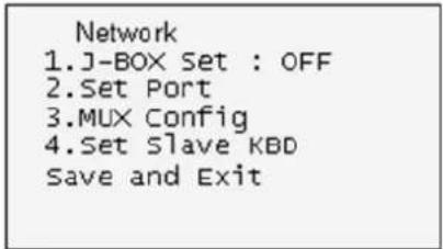
3.2 Network
| 1. J-BOX Set: OFF | Select to use the optional Junction Box or not. |
| 2. Set Port | Select the baud rate and the connected unit's protocol. |
| 3. MUX Config | Set the multiplexer configuration. |
| 4. Set Slave KBD | Select to use the slave keyboard or not. |
| Save and exit | Save the changed settings and return to the previous menu |
Set Port
- Set Baud Rate
2.Com Ports
Exit(ESC)
| Set Baud Rate | Enters the Baud Rate setup submenu. |
| Com Ports | Enters the Communications Ports setup submenu. |
| Exit | Return to the previous menu. |
Set Baud Rate
Set Baud Rate
KBDDUP : Keyboard + Duplex Multiplexer
KBDTRI : Keyboard + Triplex Multiplexer
AUX IN : outputs the auxiliary signal input to Dome1(FASTRAX,PELCO only)
Note: When the DVR is selected at a port, the other port displays the same DVR only. To change the DVR number at the other port, first change the current DVR number to none.
Note: JBOX is an optional device that is not included with the KBD.
JBOX menu has to be set to OFF in the menu if you do not have this optional JBOX.
MUX Config (Multiplexer Configuration)
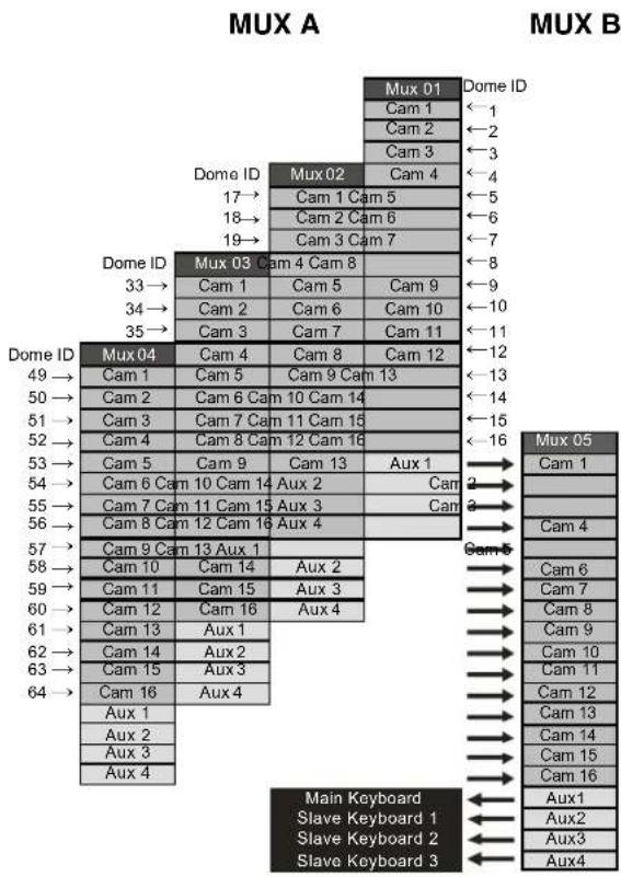
This screen allows you to set multiplexer switching settings when you select the camera by pressing NO + CAM. Up to 64 Cameras can be installed using 5 MUXs and 4 keyboards. It is equivalent to a 64x4 matrix system. Each four users can view one of 64 cameras to his own SPOT(AUX) monitor.
| MUX Config |
| 1.MUX Channel : 16 |
| 2.Set MUX A |
| 3.Set MUX B |
| Save and Exit |
This menu is for assignment when multiplexers are installed in two levels. Two levels means that spot outputs of the first level multiplexers is connected to the video input of the second level multiplexer.
Press NO + CAM will display the selected camera on the spot output of the second level multiplexer.
MUX Channel: NO(no use), 16, 28, 32, 48, 64 – Select the MUX channel number used in the multiplexer configuration.
When you select the desired number, the MUX configuration table is made automatically according to the number as the figure 8.
When the configuration is different from the auto-setting, you can change the value individually as below.
Set MUX A
| Cam<- | MUX | In | Out |
| 0001 | 001 | 01 | 01 |
This menu is for assignment the first level (A level) of MUX.
Cam : Dome camera ID
MUX : MUX ID
In : Input of MUX
Out : Spot Output number of the MUX
(01: master keyboard, 02: slave keyboard 1, 03: slave keyboard 2, 04: slave keyboard 3)
- Move the cursor ( ) on the Cam column by the joystick.
- Twist the joystick handle to change the value.
- Move the cursor ( ) on the MUX column by the joystick.
- Twist the joystick handle to change the value.
- Move the cursor ( ) on the In column by the joystick.
- Twist the joystick handle to change the value.
- Press CTRL or ESC to exit.
- To save data, move the joystick right on 'Save and Exit' row in MUX Config.
Press OFF to delete the camera number.
Set MUX B
| Cam<- | MUX | In | Out |
| 0001 | 005 | 01 | 01 |
This menu is for assignment the second level (B level) of MUX.
Cam : Dome camera ID
MUX : MUX ID
In : Video Input number connected from the spot output of the first level's MUX.
Out : Spot Output number of the MUX
(01: master keyboard, 02: slave keyboard 1, 03: slave keyboard 2, 04: slave keyboard 3)
For example: When the MUX channel is 64:
At the master keyboard, pressing 64 + CAM is operates as below.
| Cam<- | MUX | In | Out |
| 0064 | 004 | 16 | 01 |
| Cam<- | MUX | In | Out |
| 0064 | 005 | 13 | 01 |
MUX A: the multiplexer 04 outputs camera (ID=64) of the video input 16 to the spot output 1.
MUX B: the multiplexer 05 outputs the camera (ID=64) of the video input 13 to the spot output 1.
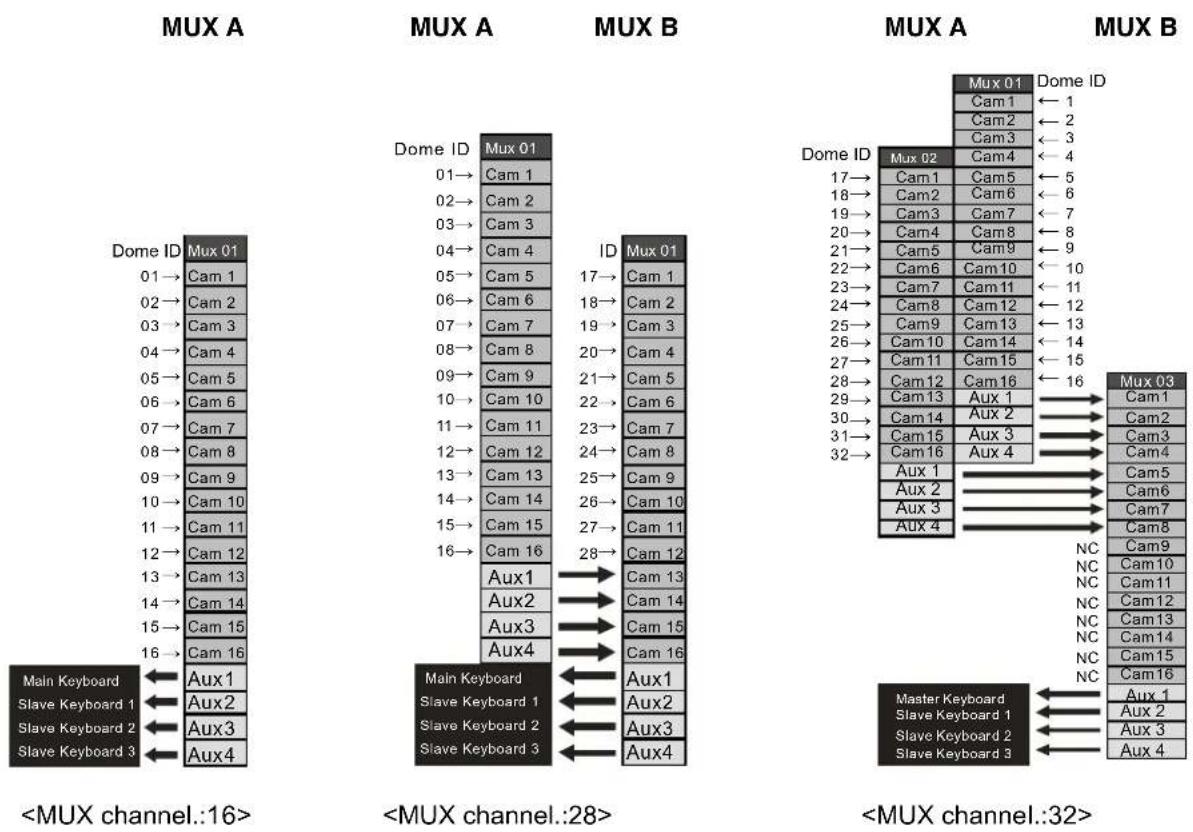
MUX A
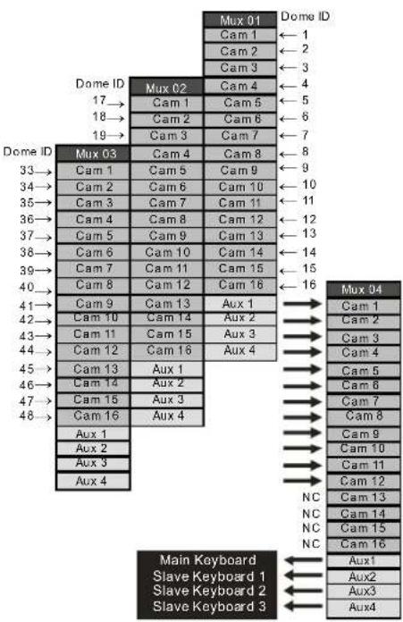
text_image
Mux 01 Dome ID Cam 1 ← 1 Cam 2 ← 2 Cam 3 ← 3 Dome ID Mux 02 Cam 4 ← 4 17 → Cam 1 Cam 5 ← 5 18 → Cam 2 Cam 6 ← 6 19 → Cam 3 Cam 7 ← 7 Dome ID Mux 03 Cam 4 Cam 8 ← 8 33 → Cam 1 Cam 5 Cam 9 ← 9 34 → Cam 2 Cam 6 Cam 10 ← 10 35 → Cam 3 Cam 7 Cam 11 ← 11 36 → Cam 4 Cam 8 Cam 12 ← 12 37 → Cam 5 Cam 9 Cam 13 ← 13 38 → Cam 6 Cam 10 Cam 14 ← 14 39 → Cam 7 Cam 11 Cam 15 ← 15 40 → Cam 8 Cam 12 Cam 16 ← 16 41 → Cam 9 Cam 13 Aux 1 Mux 04 42 → Cam 10 Cam 14 Aux 2 → Cam 1 43 → Cam 11 Cam 15 Aux 3 → Cam 2 44 → Cam 12 Cam 16 Aux 4 → Cam 3 45 → Cam 13 Aux 1 → Cam 4 46 → Cam 14 Aux 2 → Cam 5 47 → Cam 15 Aux 3 → Cam 6 48 → Cam 16 Aux 4 → Cam 7 Aux 1 Aux 9 Aux 10 Aux 2 Aux 11 Aux 3 Aux 12 Aux 4 NC -Cam 13 Main Keyboard Slave Keyboard 1 Slave Keyboard 2 Slave Keyboard 3 Aux1 Aux2 Aux3 Aux4MUX B
tree
| MUX ID | Dome ID | Cam 1 | Cam 2 | Cam 3 | Cam 4 | Cam 5 | Cam 6 | Cam 7 | Cam 8 | Cam 9 | Cam 10 | Cam 11 | Cam 12 | Cam 13 | Cam 14 | Cam 15 | Cam 16 | Main Keyboard | Slave Keyboard 1 | Slave Keyboard 2 | Slave Keyboard 3 | |---|---|---|---|---|---|---|---|---|---|---|---|---|---|---|---|---|---|---|---|---|---| | Mux 01 | Dome ID | -1 | -2 | -3 | -4 | -5 | -6 | -7 | -8 | -9 | -10 | -11 | -12 | -13 | -14 | -15 | -16 | -16 | -16 | -16 | -16 | | Mux 02 | Dome ID | -1 | -2 | -3 | -4 | -5 | -6 | -7 | -8 | -9 | -10 | -11 | -12 | -13 | -14 | -15 | -16 | -16 | -16 | -16 | -16 | | Mux 03 | Dome ID | -1 | -2 | -3 | -4 | -5 | -6 | -7 | -8 | -9 | -10 | -11 | -12 | -13 | -14 | -15 | -16 | -16 | -16 | -16 | -16 | | Mux 04 | Dome ID | -1 | -2 | -3 | -4 | -5 | -6 | -7 | -8 | -9 | -10 | -11 | -12 | -13 | -14 | -15 | -16 | -16 | -16 | -16 | -16 | | Mux 05 | Dome ID | -1 | -2 | -3 | -4 | -5 | -6 | -7 | -8 | -9 | -10 | -11 | -12 | -13 | -14 | -15 | -16 | -16 | -16 | -16 | -16 | | Main Keyboard Slave Keyboard 1 Aux1 Aux2 Aux3 Aux4Figure 8 – MUX configuration
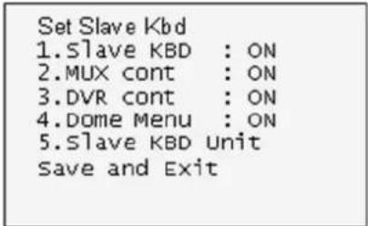
Set Slave Kbd
Set Slave Kbd
- Slave KBD : OFF
2.MUX cont : OFF
3.DVR cont : OFF - Dome Menu : OFF
5.Slave KBD Unit
Save and Exit
This screen allows you set up Slave KBD controller, how many the slave KBD controller and Mux menu controllability and DVR menu controllability, etc.
| 1. Slave KBD | ON: Slave KBD controller can control the unit which is connected Master KBD controller. |
| 2. MUX control | ON: Slave KBD controller is allowed to access Mux setup menu. |
| 3. DVR control | ON: Slave KBD controller is allowed to access DVR setup menu. |
| 4. Dome Menu | ON: Slave KBD controller is allowed to access Dome menu setup. |
| 5. Slave KBD Unit | Enters the Slave keyboard unit submenu. |
| Save and exit | Save the changed settings and return to the previous menu |
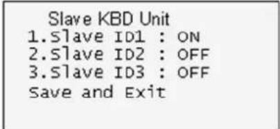
Slave KBD Unit
Slave KBD Unit
This setup allows you set up the slave keyboard, how many slave keyboards.
To use the slave keyboard, set ON.
3.3 Camera
Cam : Camera ID
PR : Protocol[F2,F2E,P-D(PELCO-D),P-P(PELCO-P)]
PT : Port[D1(DOME1),D2(DOME2)]
BR : Baud rate
| Cam<- | PR | PT | BR |
| 0001 | F2E | D1 | 9600 |
This camera setup is listed up to 64 cameras and the camera ID has up to 3999.
When the keyboard has that the Alarm Check option is ON, the camera setup is set automatically after the keyboard checks the camera at the first power on or after the scan dome function.
At this time, the F2E protocol could not be changed.
To add the other camera:
- Select the blank line (---) by moving the joystick down or up.
-
Twist the handle of the joystick clockwise, then the next camera number displays or press camera number and CAM key, if that number is not already defined, the camera number displays.
-
Set the appropriate protocol and port moving the cursor ( ) by the joystick.
Alarm check option is ON: P-D (PELCO-D), P-P (PELCO-P) Alarm check option is OFF: F2, F2E, P-D (PELCO-D), P-P (PELCO-P)
- Set the appropriate baud rate of the camera.
- Repeat step 1-4 to add a new camera.
- Press CTRL to save and exit.
- To change the camera, repeat step 2-6 after selecting the desired camera number.
Press OFF to delete the saved camera.
Press the ESC key to exit without saving.
Note) The baud rate of the F2E is according to the value of the set baud rate menu.
When the keyboard has that the alarm check option is OFF, the camera setup displays the blank value after the first power on. At this time, set all cameras according to the procedure above.
3.4 Time / Date
| TIME/DATE | |
| 1.Dispaly :ON | |
| 2.Year :2007 | |
| 3.Month :JUL | |
| 4.Day :02 MON | |
| 5.Hour :12 | |
| 6.Minute :20 | |
| Save and Exit |
Set the KBD controllers' Time & Date
3.5 ALARM
| Alarm | |
| 1.Check :ON | |
| 2.Beep :ON | |
| Save and Exit |
| 1. Alarm Check | When set to ON, the KBD controller will check alarm signal and each port can be connected 32 dome cameras. When set to OFF, it will not check alarm signal and each port can be connected 128 dome cameras. |
| 2. Alarm Beep | When set to ON, the KBD controller will sound beep when alarm signal is detected. |
| Save and exit | Save the changed settings and return to the previous menu |
NOTE: When domes are installed more than 64 at one dome port, you should set the alarm
check to OFF.
3.6 LCD
- Bright : 01\~12
- Backlight : ON/OFF
3.7 DATA BANK
LCD
1.Bright :03
2.Backlight :ON
Save and Exit
Data Bank
1:Download->
2:Download->
Exit(ESC)
The data bank function allows you to download the programmed data from the selected camera and to upload the saved data of the keyboard to the selected camera.
Push the joystick to the right to download.
Data Bank 1
065.5%
After downloading, if success, press ENTER.
Data Bank 1
Download OK
After downloading, if fail, press ENTER
Data Bank 1
Download Error
After downloading, it displays as the right figure.
Data Bank
1:0001E
2: Download->
To upload, select the upload and push the joystick to the right.
Data Bank 1
Upload
Clear Data
Exit(ESC)
To clear the saved data, select the clear data and push the joystick to the right.
3.8 INITIALIZATION
To initialize the keyboard, select Initialization.
After Initialization, the keyboard returns it to the factory value.
MAIN MENU
- Initialization
ARE YOU SURE?
ENTER OR ESC
3.9 HOLD TIME
MAIN MENU
9.Hold time:005s
When the dome ID of the master keyboard is the same as the slave keyboard or the one from AUX IN mode(dome2 port), during the hold time after the master keyboard control the dome, the slave keyboard and the unit from the AUX IN mode(dome2 port) cannot control the dome.
| INF (Infinite) | Slave Keyboard user never has the right to control the dome which is selected by master Keyboard users. |
| 1 ~ 200 second | After select hold time, the slave keyboard can control the dome. |
When the dome ID of the master keyboard is not the same as the slave keyboard or the one from AUX IN mode (dome2 port), the hold time has no relation.
Chapter 4 — Slave Keyboard Setup
Master keyboard should be setup as following procedure.
- Check for dip switch the 8 ^th of S1 "OFF".
- Press CTRL + MENU. Check Slave KBD setting "ON".
Network ▶ Set Slave KBD ▶ Slave KBD : ON
Network ▶ Set Slave KBD ▶ Slave KBD Unit: ON for the desired slave keyboard
Slave keyboard need to be setup with the following procedure.
- Check for dip switch the 8^th of S1 is “ON”.
- If you setup all connection correctly and turn on slave keyboard, you should see following screen.
Ver x.x Slave1
Password : xxxx
←Current Device ID = 1
←Default setting is 9 9 9 9 for administrator, 1 1 1 1 for user
Not connected
←means that the controller is not connected to master keyboard
- Press CTRL + MENU, Set the Slave ID to 01
MAIN MENU
- Configuration
- Network
- LCD
- Initialization
Exit(ESC)
Configuration
- Key Beep : ON
2.key Lock : OFF
3.Chg User PW
4.Chg Admin PW
Save and Exit
Network
1.J-BOX Set : OFF
2. Keyboard ID : 01
3.BPS:9600
Save and Exit
LCD
1.Bright :03
2. Backlight : ON
Save and Exit
Chapter 5 — Install with DVR Series
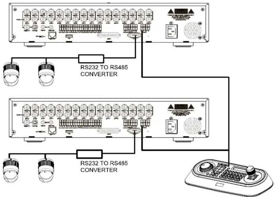
5.1 Install with Standalone DVR Series
When user wants to connect with DVR, proceed as the following order.

flowchart
graph TD
    A["J-BOX"] --> B["DOME"]
    C["RS485(+) DOME1 + RX+(TX+)"] --> B
    D["RS485(-) DOME1 - RX-(TX-)"] --> B
    B --> E["POWER AC 24V"]
    F["STP AWG #22"] --> G["UNSHIELDED CABLE"]
    G --> H["KEYBOARD CONTROLLER"]
    H --> I["REAR"]
    I --> J["STANDALONE DVR SERIES"]
    J --> K["REAR"]
    style A fill:#f9f,stroke:#333
    style C fill:#f9f,stroke:#333
    style D fill:#f9f,stroke:#333
    style F fill:#ccf,stroke:#333
    style H fill:#cfc,stroke:#333
    style I fill:#fcc,stroke:#333
    style J fill:#cff,stroke:#333
    style K fill:#ffc,stroke:#333
-
Connect RS232 cable between RS-232 Port of DVR and RS232 of the Keyboard. (This connection enables DVR control remotely from KBD controller)
-
How to setup the KBD controller.
A. Turn the Keyboard ON
B. Input password (Factory setting is 9999)
C. Open the menu of the KBD controller by pressing CTRL + MENU Key.
D. Set as below in Network menu.
text_image
Quick Setup Quick Setup On Recording Speed/Quality 60 ips High Audio Recording Off Sequence Dwell Time 3 sec System Information... Camera... Network Setup... Password... Date/Time... OK CancelA. Press "OK", and the below screen will be appeared.
text_image
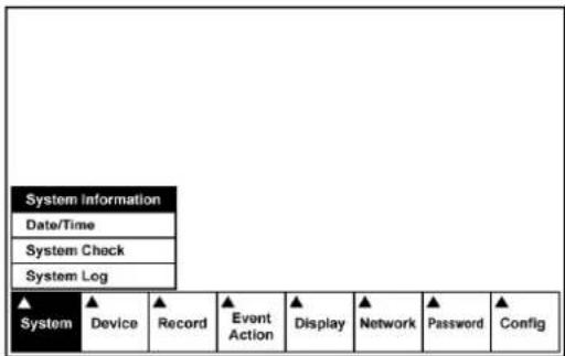
System Information Date/Time System Check System Log ▲ System ▲ Device ▲ Record ▲ Event Action ▲ Display ▲ Network ▲ Password ▲ ConfigB. Select "System Information" on the system menu and change UNIT ID.
text_image
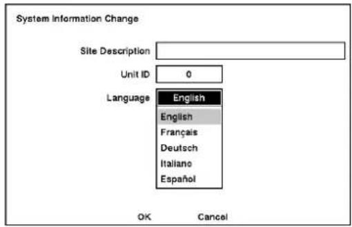
System Information Change Site Description Unit ID 0 Language English English Français Deutsch Italiano Español OK CancelC. Select "Camera" on the Device menu. Unit ID should be 1 up to 99. Unit ID is not allowed number "0".
text_image
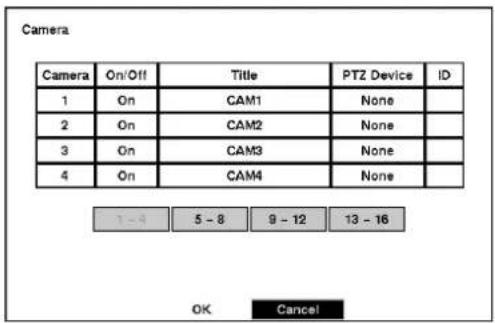
Camera Camera On/Off Title PTZ Device ID 1 On CAM1 None 2 On CAM2 None 3 On CAM3 None 4 On CAM4 None 7 - 9 5 - 8 9 - 12 13 - 16 OK CancelD. Set "PTZ Device" and "ID" of the dome camera. Select RS232/RS485 after PTZ is installed, and then set-up as below table.
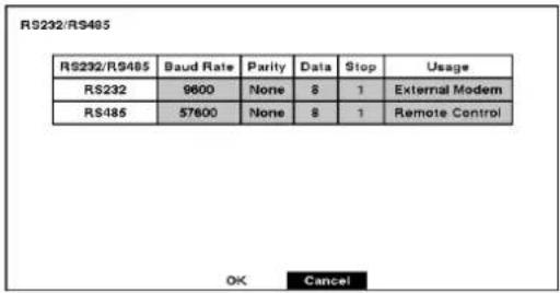
text_image
RS232/RS485 RS232 / RS485 Baud Rate Parity Data Stop Usage RS232 9600 None 8 1 External Modem RS485 57600 None 8 1 Remote Control OK Cancel| RS232/RS485 | Baud Rate | Parity | Data | Stop | Usage |
| RS232 | 9600 | None | 8 | 1 | Remote Control |
| RS485 | 9600 | None | 8 | 1 | PTZ Control |
-
After setting Unit ID, Camera, and RS232/RS485, installing dome camera is basically completed. Please refer to the manual of DVR for the other installation.
-
Press the related number of the controller which is correspondent to unit ID of DVR. Then press DVR button and adjust unit ID of the controller
-
Make sure if any change is appeared on screen when you press ☐ button of the controller for basic testing. If there's no change appeared, verify cable connection and setting of installation.
5.2 Install with PC DVR Series
If user wants to connect with PC DVR, please proceed as the following order.

text_image
22 AWG STP CABLE WIRE CONNECTION DOME JUNCTION BOX R(T)X+ DOME1+ R(T)X- DOME1 - CONVERTER JUNCTION BOX TX+(RS-485) DOME2+ TX-(RS-485) DOME2 - RS-232 CABLE Remote control PTZ control from DVR RS-232C to RS-485 CONVERTERFigure 11 – PC DVR Connection Diagram
-
Connect RS-232C cable between RS-232C Port of PC DVR and RS-232C port of the Keyboard. (This connection enables PC DVR control remotely from KBD controller)
-
Plug the RS-232C TO RS-485 converter in the RS-232C Port of PC DVR. Connect wires between the TX(+/-) of converter and DOME2(+/-) of Keyboard. (This connection enables PC DVR PTZ control from KBD controller)
-
How to setup the KBD controller.
A. Switch the KBD controller ON
B. Input password (Factory Setting is 9 9 9 9)
C. Open the menu of the KBD controller by pressing CTRL + MENU Key.
D. Set as below in Network menu.
4. How to setup PC DVR
A. Switch the PC DVR on.
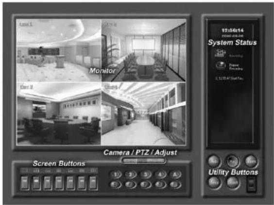
text_image
12:50:14 System Status Monitor Camera / PTZ / Adjust Screen Buttons Utility ButtonsB. If press setup button on the above screen, the below screen will be appeared.

text_image
Setup System Camera Schedule Sensor Motion Detector Alarm Remote CAMERA Select a camera For each camera Description Cam1 PTZ Set up PTZ... Hide Image Show Image Color Text for Hidden camera: LOOKED Same configuration for all cameras Advanced Setup Recording speed 1/4 30sec 1/30sec Post-event rec. speed 1/8 30sec 1/30sec Post-event rec. width 0.019 sec 10min Pre-event recording: Pre-event rec. speed 1/2 30sec 1/30sec Pre-event rec. width 0.019 sec 10min Rec. image modulation 30K-240 100 640 Rec. image quality: Medium Low Very High ... Default... The recording speed may not be achieved when averaged over all the cameras. Load Save Default OK CancelC. Select camera input number that dome camera connected. Then install as below to select set-up PTZ after checking PTZ box.
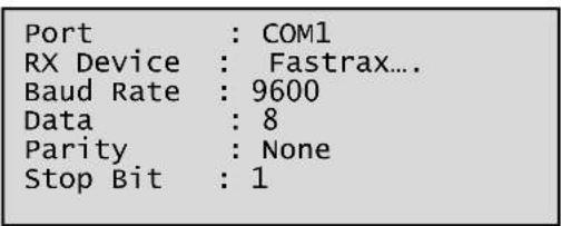
text_image
Port : COM1 RX Device : Fastrax.... Baud Rate : 9600 Data : 8 Parity : None Stop Bit : 1D. If PTZ is not necessary for PC DVR, cable and installation here is not needed. (PC DVR is able to be controlled remotely and there's no PTZ function)
5. How to PC DVR Remote setup
A. If selects Setup on main menu, the below screen will be appeared.
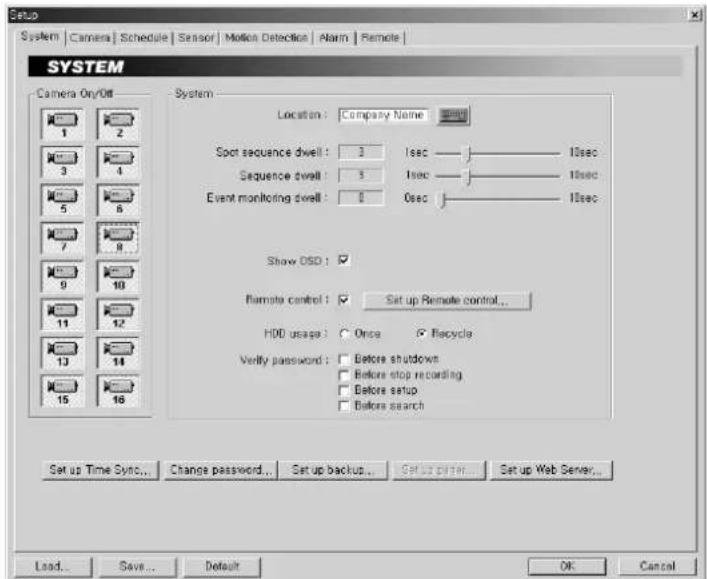
text_image
Setup System | Camera | Schedule | Sensor | Motion Detection | Alarm | Remote | SYSTEM Camera On/Off 1 2 3 4 5 6 7 8 9 10 11 12 13 14 15 16 System Location : Company Name Spot sequence dwell : 3 1sec — 10sec Sequence dwell : 3 1sec — 10sec Event monitoring dwell : 0 0sec — 10sec Show OSD : Remote control : ✓ Set up Remote control... HDD usage : Once ✓ Recycle Verify password : □ Before shutdown □ Before stop recording □ Before setup □ Before search Set up Time Sync... Change password... Set up backup... Setup paper... Set up Web Server... Load... Save... Default OK CancelB. After selecting System and checking Remote control box, please install as below to select Setup remote control. Device ID is not allowed number "0".

C. Make sure if any change is appeared on screen to press QUAD (Next Screen) button of a controller for basic testing. If there's no change appeared, check cable connection and installation again.
Chapter 6 — Operation
6.1 Keyboard Lock/Unlock (Hidden command)
When the user leaves the control desk, he may wish to lock the keyboard controller to prevent unauthorized use.
Pressing 7 7 7 + ENTER will lock the keyboard controller. Pressing 7 7 7 + ENTER while the keyboard is locked will open the password screen. If the correct password is entered, the keyboard controller will return to normal operation.
If the power is turned OFF and ON while the keyboard is locked, it will ask for the password. Entering the correct password will cause the keyboard controller to return to normal operation.
NOTE : If you forget your own passwords, turn off the keyboard controller, contact your distributor to get a 4-digit back door password. This will change the passwords to the factory default. Contact your distributor to get the 4-digit back door password.
6.2 Controlling Multiplexer
Using a multiplexer allows more flexibility in the types of cameras that can be used in a full system. Dome cameras and regular cameras can be mixed.
The keys , 2× 2 , 3× 3 , 4× 4 , , , etc., are keys that are used to operate the multiplexer.
6.2.1 Selecting Multiplexer
Duplexer : Press MACRO/MENU key to enter Multiplexer set up menu and hold down the ENTER Key while navigating using the joystick. (ENTER+Joystick)
Triplexer : Push the Joystick upward with the ENTER pressed ENTER+Joystick) will show the Mux menu. It will act like a mouse. Rotating the handle clockwise will act like the set key of the multiplexer. Rotating counterclockwise will act like the ESC key of the Multiplexer.
Selecting multiplexer (Mux ID No. + MUX)
Example: If the unit address of the Multiplexer is 128, you should press 1 2 8 + MUX to control the 128th Multiplexer.
6.2.2 Dome Camera Selection
Selecting camera (No. + CAM)
With these selections, the keyboard controller has full control of the selected camera if it is a dome camera.
Viewing full screen mode (Mux ID No. + MUX, Multiplexer video input No. + MAIN)
Select cameras 1 to 16 by pressing the camera number and then Main. The selected camera will appear in the full screen mode and is under control if it is a dome camera.
Picture on Spot output monitor (SPOT No. + SPOT + Camera No. + ENTER)
Pressing SPOT No. + SPOT + Camera No. + ENTER will switch the selected camera number to the specific spot monitor output of the multiplexer. The selected camera can be a dome camera or a standard camera. The Keyboard controller maintains control of the previously selected dome camera. It does not change the main output of the multiplexer.
Example:
1 + MUX, 2 + SPOT + 12 + ENTER will switch camera 12 on multiplexer 1 to the spot output 2 of multiplexer 1.
2 + MUX, 1 + SPOT + 16 + ENTER will switch camera 16 on multiplexer 2 to the spot output 1 of multiplexer 2.
6.3 Summary of Keyboard Controls
Key operation example
CTRL + MENU : Press and hold down CTRL Key and press MENU Key.
1 + CAM : Press 1 Key, CAM Key sequentially.
CTRL + JOYSTICK : Press and hold down CTRL Key while manipulate Joystick Handle.
ENTER + JOYSTICK : Press and hold down ENTER Key while manipulate Joystick Handle.

text_image
CAM MUX OVR MACRO VIEW PRP 2X3 3X3 4X4 2ND LREC VCR /CO MAIN SPOT SEQ FRE ZOOM PTZ SET PRET SCAN PTRN TOUR ALUM HOME MINI ESC ENTER CTRL6.3.1 Keys for Dome camera
| Function | Key Label | Descriptions |
| Camera Selection |  | Displays the selected camera on the spot out of the multiplexer and allows the camera to be controlled by the keyboard controller, if the selected camera is a dome camera.Function number selection with function keys.(e.g., 1 + CAM, 3 + TOUR, 5 + SCAN, 6 + PRST) |
| Cancel |  | Cancels current inputs.Exits from currently running functions or menu, error status, etc. |
| Alarm |  | Disregards all currently activated alarms and turns off the beep temporarily. alarm is activated again within the programmed hold time, the timer will restart and beep again. |
| Relay ON |  | Relay No. 1-4+ONwill activate the selected relay. |
| Relay OFF |  | Relay No. 1-4+OFFwill disable the selected relay. |
| Home |  | Immediately calls Home function.Deletes selected value or function in programming mode |
| Global |  | Sends all cameras to preset (e.g., 1, 2... 5 5 + ENTER).8 8 8+ENTER: Night shot mode, 9 9 9+ENTER: Normal mode |
| Call Preset position |  | Pressing Prst will bring up the preset programming menu.Recalls preset;( e.g.: 1, 2... 3 1... 2 4 0 +PRST)In the preset or tour programming mode, the operator can review the exiting preset (selected by cursor) by pressing this key. |
| Tour |  | Pressing TOURwill bring up the tour programming menu directlyRecalls programmed presets or functions sequentially. (e.g., 1+TOUR) |
| Pattern |  | Pressing PTRNwill bring up the pattern programming menu directly.Repeats the selected pattern of the current dome camera. (e.g., 1+PTRN) |
| Auto Scan |  | Pressing Scan will bring up the Auto Scan programming menu.Calls Auto panning function (e.g., 2+SCANrepeats Auto Scan 2). |
| Configurati on |  | Enters programming menu.CTRL+MENUwill invoke Keyboard set up menu |
| Program |  | No. + CTRL+PRSTwill store current view as a preset directly.No. + CTRL+TOURwill open programming menuNo. + CTRL+SCANwill open programming menu |
| Control |  | CTRL+Joystick: In a programming mode (Preset, Pattern, Scan, Privacy....)the joystick operates as if in the normal control mode.While pressing and holding down the CTRLkey, all movements of the joystickwill start recording when in the pattern programming menu.CTRL+Joystick: In normal operation mode, manual speed of the joystickcontrol will be operated in turbo mode. |
| Enter |  | Completes entering data for the password or titleENTER+Joystick: Direction key in DVR remote mode or Mux ( PTZ, Mouse,Cursor) |
| Manual Focus |  | Overrides auto focus. Moving the Zoom handle reactivates Auto Focus mode. |
| Manual Iris |  | Overrides auto iris. Moving the joystick reactivates Auto Iris mode. |
| Zoom |  | Zoom control. |
| Joystick | Twist ,Up / DownLeft / Right | Zoom control (proportional to position) Tilt control, Cursor Up / Down in the menuPan control, Cursor Left / Right or Page scroll in the Menu. |
6.3.2 Keys for Multiplexer
| Function | Key Label | Descriptions |
| Select Mux ID |  | Select Multiplexer (e.g.; 1 or 2 + MUX) |
| Full Screen |  | Puts the multiplexer in Full-Screen Mode of the selected camera No. |
| PiP |  | Picture-in-Picture mode. |
| 2 by 2 Display |  | Displays view of four cameras. The remaining cameras can be sequenced in the lower-right window. |
| 3 by 3 Display |  | Displays view of nine cameras. The remaining cameras can be sequenced in the lower-right window. |
| 4 by 4 Display |  | Displays view of 16 cameras in 1/16-size pictures. |
| 2nd |  | Second mode of PIP multiplexer. Pressing 2nd+ENTER again will return to normal mode. |
| Panic record |  | Put a camera in the Panic Record Mode. |
| Macro |  | Same as Menu key in the Duplexer model.Same as Macro key in the Triplexer model. |
| Select or Alarm |  | Same as Select key in the Duplexer model.Same as Alarm key in the Triplexer model. |
| Freeze |  | Freeze the video from the currently selected camera. |
| Digital Zoom |  ZOOM ZOOM | Enter the Zoom Mode. |
| Sequence |  | Put the multiplexer in the Sequence Mode. |
| VCR |  | Switch the multiplexer into VCR playback mode. |
| SET |  | This button has several functions. It brings up a Popup menu, set selections on the OSD menus and decreases numbers in the number setup function. |
| Spot output |  | Displays selected camera as spot output of the current Multiplexer.(e.g., 2 + SPOT +1 + ENTER will display camera 1 as a spot output 2of the current Multiplexer) |
| Cursor movement |  | Up / Down / Left / Right control in the ZOOM and SET UP mode.Handle turn clockwise for SET mode.Handle turn counterclockwise for ESC mode. |
6.3.3.1 Keys for DVR [DVR1-4, PC-DVR]
| Function | Key Label | Descriptions |
| Id Selection | ![REVO REJCPTZ-1 - Keys for DVR [DVR1-4, PC-DVR] - 1](/content/2026/06/1188952/images/cc0584e6e3ef6b780c4642af93c416dabbf614c343497e88f80f97dda6aa36d7.jpg) | DVR ID Selection. (e.g.:1 or 2 + DVR). |
| MENU | MACRO [z8z6] | Enter the Quick Setup screen. You will need to enter the administrator password to access the Quick Setup. Pressing the button also closes the current menu or setup dialog box. |
| Record | ![REVO REJCPTZ-1 - Keys for DVR [DVR1-4, PC-DVR] - 2](/content/2026/06/1188952/images/5bce9374c4997aec4585a556b652e07d59b2deea9e5091a7e2c83ed0ddb9c25b.jpg) | [DVR1,DVR3] Record on and off.[DVR2,DVR4] Turn the panic record on and off. |
| Recall Preset | ![REVO REJCPTZ-1 - Keys for DVR [DVR1-4, PC-DVR] - 3](/content/2026/06/1188952/images/34f6e493d4b593ad931c1910885626f9a574997544b5ff5de96125253ea41fe8.jpg) | Recall the preset number in the PTZ mode. |
| Rewind | ![REVO REJCPTZ-1 - Keys for DVR [DVR1-4, PC-DVR] - 4](/content/2026/06/1188952/images/51dfa69972b227445529af7419afc21bd4b09394cb2deeb04e03902dfa59fe9e.jpg) | Play video backward at high speed. Pressing the button again toggles the playback speed from ,and, |
| Reverse Play | ![REVO REJCPTZ-1 - Keys for DVR [DVR1-4, PC-DVR] - 5](/content/2026/06/1188952/images/6f4f523567388a107e5444a214f8ee3220298e133f3847178606a21a5ef545bc.jpg) | No operation |
| Play/Pause | ![REVO REJCPTZ-1 - Keys for DVR [DVR1-4, PC-DVR] - 6](/content/2026/06/1188952/images/d42ea9580afbcba658a2a63f2a57a68efb6a2ee3dcaee1bc41cf7128c7ee6d5b.jpg) | [DVR1- 4]Play recorded data / Pause playing. [PC-DVR] Play |
| Fast Forward | ![REVO REJCPTZ-1 - Keys for DVR [DVR1-4, PC-DVR] - 7](/content/2026/06/1188952/images/17b27b374360e2c3964204a216e160234634ac10eb1df66c41f7768b309e020c.jpg) | Play video forward at high speed. Pressing the button again toggles the playback speed from ,, and |
| STOP | ![REVO REJCPTZ-1 - Keys for DVR [DVR1-4, PC-DVR] - 8](/content/2026/06/1188952/images/e148a65672bba4f3e49250bcfa7b2fcc188c306f0a3cc588270335de89847c4e.jpg) | [DVR1,DVR2]During Playback mode returns the DVR to the Live Monitoring mode. |
| SPOT | ![REVO REJCPTZ-1 - Keys for DVR [DVR1-4, PC-DVR] - 9](/content/2026/06/1188952/images/08b6cf7de7da65c3f356185d1ba6e3e7736b8e138fd83a50ce6f43419699ae78.jpg) | [DVR3,DVR4]Display the SPOT pop-up menu. |
| Save Preset | ![REVO REJCPTZ-1 - Keys for DVR [DVR1-4, PC-DVR] - 10](/content/2026/06/1188952/images/daa4eaf707bea81689ebc879dd8526b5a3602c1b2abfd97afeb04314fe107cb3.jpg) | Save the preset number in the PTZ mode. |
| Pause | ![REVO REJCPTZ-1 - Keys for DVR [DVR1-4, PC-DVR] - 11](/content/2026/06/1188952/images/9c3342271a368ad353f46caffce72fbc79123bcc9732f101c7bee1f8b525d3be.jpg) | [DVR1- 4] No operation, [PC-DVR] Pause |
| Full Screen | [czkD] | Displays selected camera in the full-Screen Mode and enter the numbers in the login menu. |
| Spot Sequence | ![REVO REJCPTZ-1 - Keys for DVR [DVR1-4, PC-DVR] - 12](/content/2026/06/1188952/images/4167ddfb7cab947ede74ad153f217490abb77e47956c2e3eb70311ccd88fe40b.jpg) | Toggle on and off sequence mode of the selected spot output. |
| Spot output | ![REVO REJCPTZ-1 - Keys for DVR [DVR1-4, PC-DVR] - 13](/content/2026/06/1188952/images/13ddfc1be93cd86444cb845109e6cd3fa4cc3061fb1118a525ddb6c397aaf501.jpg) | Displays selected camera as spot output of the current DVR . |
| Display Mode | ![REVO REJCPTZ-1 - Keys for DVR [DVR1-4, PC-DVR] - 14](/content/2026/06/1188952/images/4de36b2a88bde769c29711e46ab8d7a72f4df47d685ce7cae84217c316586dcc.jpg) | Toggle between different display formats. The available formats are: full, 4x4, 3x3, 2x2 and PIP. |
| Sequence | ![REVO REJCPTZ-1 - Keys for DVR [DVR1-4, PC-DVR] - 15](/content/2026/06/1188952/images/2465df972efedfd095b2263566865950a82f92f3a6e8d2765f0d171e3c621d1b.jpg) | When in the live mode, pressing the SEQUENCE button displays another full live channel sequentially. When in one of the multi-view formats, pressing this button will cause the DVR to sequence cameras in two sequence modes: “Page” and “Cameo”. In the Page mode, th DVR sequences through user-defined screen layouts (pages). In the Cameo mode, the bottom, right screen to display live cameras sequentially. Pressing the SEQUENCE button while in the Sequence mode will exit the Sequence mode. |
| Freeze | ![REVO REJCPTZ-1 - Keys for DVR [DVR1-4, PC-DVR] - 16](/content/2026/06/1188952/images/62f181886d30428a3edd8a3eb8ac658e797cd3a78617c1d35bfb36376768e74d.jpg) | Freeze the current live screen. |
| Search | ![REVO REJCPTZ-1 - Keys for DVR [DVR1-4, PC-DVR] - 17](/content/2026/06/1188952/images/45e788803f814697cf858eb208b3ad42e01f75286125f56b55b3eed0f50738cd.jpg) | Go to the playback mode and exit the playback mode. |
| Digital ZoomAlarm | ![REVO REJCPTZ-1 - Keys for DVR [DVR1-4, PC-DVR] - 18](/content/2026/06/1188952/images/63c9c476a5bfff392594383951c757149d5d8088329cdaac4f6ac50175cc7fb0.jpg) ![REVO REJCPTZ-1 - Keys for DVR [DVR1-4, PC-DVR] - 19](/content/2026/06/1188952/images/e57251dcfdf783557cbc67400118d7c8020914464c4dee3bedb6c8a1a081ac65.jpg) | [DVR1- 4] Enter the digital zoom mode when DVR has the digital zoom function.First, it will reset the DVR's outputs including the internal buzzer during an alarm. Second, it will display the event log when you are in the live monitoring mode unless there is an active alarm. |
| Enter | ![REVO REJCPTZ-1 - Keys for DVR [DVR1-4, PC-DVR] - 20](/content/2026/06/1188952/images/6a3e8d3bd256f6a9e07f53c81fc82ec2d4bdbe78f6f6607b0c5e71f716c5ae87.jpg) | [DVR1- 4]Select a highlighted item or completes an entry that you have made. |
| Cursor movement | ![REVO REJCPTZ-1 - Keys for DVR [DVR1-4, PC-DVR] - 21](/content/2026/06/1188952/images/9d41653a3357f2bc1dcd35880189d913b55e3ab53f8d9d5a4245b4578f51f900.jpg) | Up / Down / Left / Right control in the digital zoom and SET UP mode. Handle turn clockwise for SET mode. Handle turn counterclockwise for ESC mode. |
| Shuttle | The Shuttle Ring operates in the Playback mode only. Turning the ring clockwise plays video forward. Turning the ring counterclockwise plays video backward. | |
| Jog | The Jog Dial operates only when playback video has been paused. By turning the jog dial clockwise, you can play video forward image-by-image. | |
| Cam Selection | ![REVO REJCPTZ-1 - Keys for DVR [DVR1-4, PC-DVR] - 22](/content/2026/06/1188952/images/46d03180a7a47d5e8f7f8bd2c4203a0803540d5e6b5b39e70e6ba11e61af9c9c.jpg) | [PC-DVR] Select the camera and change the camera in the full-screen mode. |
| Display Mode | CTRL + 1 ~ CTRL + 9 | [PC-DVR] Change screen mode. |
| Go last | ![REVO REJCPTZ-1 - Keys for DVR [DVR1-4, PC-DVR] - 23](/content/2026/06/1188952/images/18073f2697f30a7d16a3863500bda7f9404c231c19434419880f039a9e55a4ca.jpg) | [PC-DVR] Go last. |
| Go last | ![REVO REJCPTZ-1 - Keys for DVR [DVR1-4, PC-DVR] - 24](/content/2026/06/1188952/images/77eca37a41b3a14b0cd625311fab1cd42f7e7b5d5dc2a90ff2c2013480b83a33.jpg) | [PC-DVR] Go last. |
| X times Forward play | _![REVO REJCPTZ-1 - Keys for DVR [DVR1-4, PC-DVR] - 25](/content/2026/06/1188952/images/53c9bb692eecb4f5d1c089526d2938b73f0ea85bfc979777527400feb6af8179.jpg) | [PC-DVR] Fast play at x(No.) times speed. |
| X times Backward play | _![REVO REJCPTZ-1 - Keys for DVR [DVR1-4, PC-DVR] - 26](/content/2026/06/1188952/images/96e870d3df81d671064685e4d40d4cda233f40205fcf0ee41fe5b52851394489.jpg) | [PC-DVR] Fast rewind at x(No.) times speed. |
| PTZ | ![REVO REJCPTZ-1 - Keys for DVR [DVR1-4, PC-DVR] - 27](/content/2026/06/1188952/images/918d0dec42c38b6cda0c93a9da48180e9981b93d8d66756b75cd2eec72ac2f9b.jpg) | [DVR1- 4] Open a Pan/Tilt/Zoom screen which allows you to control properly configured PTZ cameras. |
| Manual Focus | ![REVO REJCPTZ-1 - Keys for DVR [DVR1-4, PC-DVR] - 28](/content/2026/06/1188952/images/286bf25b1e2ee401cdb4ab565f4328a511407ba809eb5a9fa3625825b4022414.jpg) | When a PTZ camera is connected to the DVR, it can control the focus. Moving the Zoom handle reactivates Auto Focus mode. |
| Manual Iris | ![REVO REJCPTZ-1 - Keys for DVR [DVR1-4, PC-DVR] - 29](/content/2026/06/1188952/images/f7b258ef7c61fd8b1778dc8e1ff7dd9a6c989d48b6c561a37a7e09f81c2bc0d9.jpg) | When a PTZ camera is connected to the DVR, it can control the IRIS. Moving the joystick reactivates Auto Iris mode. |
| Zoom | ![REVO REJCPTZ-1 - Keys for DVR [DVR1-4, PC-DVR] - 30](/content/2026/06/1188952/images/8daf8fcc2aa2a288d06f3c75f7f7111762b8c1ac37ea2a28d8a800c351d49778.jpg) | When a PTZ camera is connected to the DVR, it can control the zoom position. |
| movement | ![REVO REJCPTZ-1 - Keys for DVR [DVR1-4, PC-DVR] - 31](/content/2026/06/1188952/images/36de88c2e8172b42c6a687e88168f4650be0c27ba371bcb56064280c3da8e633.jpg) | Up / Down / Left / Right control in the PTZ mode. Handle turn clockwise or counterclockwise for then zoom control. |
* When DVR has the record button, select DVR1
* When DVR has the panic record button, select DVR2
* When DVR has the record button and the spot button, select DVR3
* When DVR has the panic record button and the spot button, select DVR4
* When DVR is the PC based DVR, select PC-DVR
* The key for the dome control operates only when the dome is connected to the DVR by RS485 and the DVR is in the PTZ mode.
6.3.3.2 Example of Key operation in PC-DVR
| Function | Key Label | Live(Guard) Mode | Playback Mode |
| MENU |  MACRO MACRO | NO ACTION | |
| Record |  | Record ON / OFF | |
| Recall Preset |  | Recall Preset | |
| Search |  | Go to Playback mode | Stop |
| Rewind |  | NO ACTION | Rewind one image |
| X times Backward play |  | NO ACTION | Fast rewind at x(No.) times speed. |
| Reverse Play |  | NO ACTION | Reverse Play |
| Play/Pause |  | NO ACTION | Play |
| Fast Forward |  | NO ACTION | Forward one image |
| X times Forward play |  | NO ACTION | Fast play at x(No.) times speed. |
| STOP |  | NO ACTION | Go to Guard mode |
| Save Preset |  | Save Preset | |
| Pause |  | NO ACTION | Pause in playing |
| Full Screen |  | NO ACTION | |
| Spot Sequence | Spot No.+  ENTER ENTER | Operate according to the model or not | |
| Spot output | Spot No.+  camera No.+ camera No.+  | Operate according to the model or not | |
| Display Mode |  | Change Display Mode | NO ACTION |
| Sequence |  | Sequence | NO ACTION |
| Freeze, PTZ, Enter |  | NO ACTION | |
| Camera Selection | No.+  | Camera Selection | |
* For example, press to enter the playback mode.
6.4 DVR5 protocol for the DVR for the version 3.1.0 and over
Installation of the DVR5 protocol when one DVR is used.
Note: When you set the protocol to DVR5, the keyboard operates as the DVR's keyboard only and you must install domes to the DVR only.

text_image
RS232When you control the PTZ camera by the DVR, follow as below.
- Connect RS232 cable between RS-232 Port of DVR and DVR port of the J-box. (This connection enables DVR control remotely from KBD controller)
- Connect RS485 cables between the DVR and PTZ cameras.
- Connect the power jack to the power port of the keyboard.
A. Input password (Factory setting is 9999)
B. Open the menu of the KBD controller by pressing CTRL + MENU Key.
C. Set as below in Network menu.
Note: The baud rate of DVR/AUX should be the same as one of the RS232 of the DVR
4. How to setup DVR:
D. Switch the DVR on.
E. Enter the Menu according to the DVR's instruction manual.
F. Change the Port to "RS232" of the remote control in the devices menu.
G. Confirm matching the setup of RS232 with the keyboard.
Ex: Baud Rate:9600, Data Bit:8, Stop Bit:1, Parity:None)
H. Change the Remote Control to "Remote Control2" in the devices menu.
I. Change the Port to "RS485" in the PTZ menu of the camera of the devices menu.
J. Confirm matching the setup of RS485 of the PTZ menu with PTZ cameras.
K. Set the PTZ menu according to PTZ cameras.
Note: The baud rate of all PTZ cameras should be used one speed type (ex. All 9600 or all 2400)
Note: The product of FASTRAX should be used "FASTRAX2"
L. Set the ID number according to PTZ cameras.
M. Set the system ID number to 1.
Operation of the keyboard
When the PTZ camera is installed on the DVR, you should select the number of the input channel not the ID number of the PTZ camera.
For example, when the PTZ camera with the 5 ID number is installed the number 1 of the input jack of the DVR, to control the camera, you select 1 + CAM not 5 + CAM.
| Action | Key pressing | Remark / LCD display |
| DVR selection | 1 + DVR | Displays DVR-001 at the top line |
| Camera selection | 1 + CAM | CAM:0001 at the top lineDVR-001 at the top line |
| 17 + CAM | CAM:0017 at the top lineDVR-001 at the top line | |
| Camera selection of DVR #2 | 2 + DVR | CAM:0017 at the top lineDVR-002 at the top line |
| Camera 1 selection of DVR #2 | 1 + CAM | CAM:0001 at the top lineDVR-002 at the top line |
| Return to DVR #1 | 1 + DVR | CAM:0001 at the top lineDVR-001 at the top line |
| Full-screen selection | 1 + MAIN | CAM:0001 at the top lineDVR-001 at the top line |
| 16 + MAIN | CAM:0016 at the top lineDVR-001 at the top line | |
| 32 + main | CAM:0032 at the top lineDVR-001 at the top line | |
| Return to DVR #2 | 2 + DVR | CAM:0032 at the top lineDVR-002 at the top line |
| Control SPOT output | 1+SPOT + 1+ENTER | Camera 1 goes to SPOT 1 output |
| 2+SPOT + 16+ENTER | Camera 16 goes to SPOT2 output | |
| 1+SPOT + ENTER | Sequence SPOT 1 output | |
| 1+SPOT + ENTER | Stop the sequence of SPOT 1 output |
Installation of DVR5 protocol when many DVR use.
flowchart
graph TD
    A["Server Rack 1"] --> B["RS232 TO RS485 CONVERTER"]
    C["Server Rack 2"] --> D["RS232 TO RS485 CONVERTER"]
    B --> E["Control Panel"]
    D --> E
    style A fill:#f9f,stroke:#333
    style C fill:#f9f,stroke:#333
    style B fill:#ccf,stroke:#333
    style D fill:#ccf,stroke:#333
    style E fill:#dfd,stroke:#333
When you control PTZ cameras on many DVRs, you need RS232 to RS485 converter. PTZ cameras are connected to RS232 to RS485 converter by the RS232 port of the DVR and the keyboard is connected through the RS485 port of the DVR.
Follow as below.
-
Connect RS485 cable between RS485 Port of DVR and the DOME1 port of the keyboard.
-
Connect RS232 cable between RS-232 Port of DVR and the RS232 Port of the RS232 to RS485 converter.
-
Connect PTZ cameras to the RS485 Port of the RS232 to RS485 converter.
-
Repeat the step 1-3 each DVR.
-
Set the system ID number of each DVR from 1 to the last DVR increasing 1.
-
Set the network menu of the keyboard as below.
Note: The baud rate of DOME1 should be the same as one of the RS485 of the DVR.
- How to setup DVR:
A. Switch the DVR on.
B. Enter the Menu according to the DVR's instruction manual.
C. Change the Port to "RS485" of the remote control in the devices menu.
D. Confirm matching the setup of RS485 with the keyboard.
Ex: Baud Rate:9600, Data Bit:8, Stop Bit:1, Parity:None)
E. Change the Remote Control to "Remote Control2" in the devices menu.
F. Change the Port to "RS232" in the PTZ menu of the camera of the devices menu.
G. Confirm matching the setup of RS232 of the PTZ menu with PTZ cameras.
H. Set the PTZ menu according to PTZ cameras.(PRODUCT and ID)
Note: The baud rate of all PTZ cameras should be used one speed type(ex. All 9600 or all 2400)
Keys for Dome camera:
| Key Label | Descriptions | |
| Camera selection |  | Displays the selected camera number. |
| Cancel |  | Cancels current inputs.Exits from currently running functions or menu, error status, etc. |
| Alarm |  | No Action |
| Home |  | Immediately calls Home function.Deletes selected value or function in programming mode |
| Call Preset position |  | Pressing Prst will bring up the preset programming menu.Recalls preset;(e.g.: 1, 2 ... 3 1 ... 2 4 0 + PRST)In the preset or tour programming mode, the operator can review the exiting preset (selected by cursor) by pressing this key. |
| Tour |  | Pressing TOUR will bring up the tour programming menu directlyRecalls programmed presets or functions sequentially. (e.g., 1 + TOUR) |
| Pattern |  | Pressing PTRN will bring up the pattern programming menu directly.Repeats the selected pattern of the current dome camera. (e.g., 1 + PTRN) |
| Auto Scan |  | Pressing Scan will bring up the Auto Scan programming menu.Calls Auto panning function (e.g., 2 + SCAN repeats Auto Scan 2). |
| Configuration |  | Enters programming menu.CTRL+MENU will invoke Keyboard set up menu |
| Program |  | No. + CTRL + PRST will store current view as a preset directly.No. + CTRL + TOUR will open programming menuNo. + CTRL + $CAN will open programming menu |
| Control |  | CTRL+Joystick: In a programming mode (Preset, Pattern, Scan, Privacy....) the joystick operates as if in the normal control mode.While pressing and holding down the CTRL key, all movements of the joystick will start recording when in the pattern programming menu.CTRL+Joystick; In normal operation mode, manual speed of the joystick control will be operated in turbo mode. |
| Enter |  | Completes entering data for the password or titleENTR+Joystick: Direction key in DVR remote mode. |
| Manual Focus | 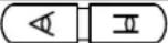 | Overrides auto focus. Moving the Zoom handle reactivates Auto Focus mode. |
| Manual Iris |  | Overrides auto iris. Moving the joystick reactivates Auto Iris mode. |
| Zoom |  | Zoom control. |
| Joystick |  | Zoom control (proportional to position).Tilt control, Cursor Up / Down in the menuPan control, Cursor Left / Right or Page scroll in the menu. |
Note: According to camera type, these functions could be different from the description.
Keys for DVR[DVR5]
*See the DVR's manual to know in detail.
| Key Label | Descriptions | |
| DVR Selection |  | DVR ID Selection. (e.g.:1 or 2 + DVR). |
| PTZ |  | Open a Pan/Tilt/Zoom screen which allows you to control properly configured cameras. |
| Play/Pause |  | Play recorded data / Pause playing. |
| Rewind |  | Play video backward at high speed. Pressing the button again toggles the playback speed from ◀, ◀ and ◀◀◀◀ |
| Fast Forward |  | Play video forward at high speed. Pressing the button again toggles the playback speed from ▶, ▶ and ▶▶▶▶. |
| Stop |  | During Playback mode returns the DVR to the Live Monitoring mode. |
| Record |  | Set the DVR so that it is ready to record video. |
| MENU |  | Enter the menu screen. You will need to enter the administrator password to access the menu if enabled. Press the menu button to see the search menu in the playback mode. Pressing the button also closes the current menu or setup dialog box. |
| Alarm |  | Invokes the event log search menu. |
| Freeze |  | Freeze the current live screen. |
| Zoom |  | Display the digital zoom screen |
| Sequence |  | Sequence. |
| Display Mode |  | Toggle between different display formats. The available formats are: full, 4x4, 3x3, 2x2 and PIP. |
| Display Mode | 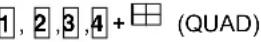 | PIP(1+Quad), 2x2(2+Quad), 3x3(3+Quad) and 4x4(4+Quad) |
| Enter |  | Select a highlighted item or completes an entry that you have made. |
| Spot Sequence | Spot  | Toggle on and off sequence mode of the selected spot output. |
| Spot output |  | Displays selected camera as spot output of the current DVR. |
| Full Screen | 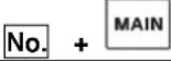 | Displays selected camera in the full-Screen Mode and enter the numbers in the login menu. |
| Cursor movement |  | Up / Down / Left / Right control in the digital zoom.Left / Right control in the quad or 3x3 screen. |
| Cursor movement | Joystick | Up / Down / Left / Right control in the menu. |
| Shuttle | The Shuttle Ring operates in the Playback mode only. Turning the ring clockwise plays video forward. Turning the ring counterclockwise plays video backward. | |
| Jog | The Jog Dial operates only when playback video has been paused. By turning the jog dial clockwise, you can play video forward image-by-image. |
Appendix A- Short Cut Key
| Short Cut Key | Function | ||
| PRST | Pop up preset setup menu. | ||
| TOUR | Pop up Tour setup menu. | ||
| PTRN | Pop up Pattern setup menu. | ||
| SCAN | Pop up Auto Scan setup menu. | ||
| NO.+PGM +PRST | Store the current view at the selected number. | ||
| Short Cut Key | Function | Short Cut Key | Function |
| 1+ON | Turn On Relay 1. | 1+OFF | Turn Off Relay. |
| 2+ON | Turn On Relay 2. | 2+OFF | Turn Off Relay. |
| 3+ON | Turn On Relay 3. | 3+OFF | Turn Off Relay. |
| 4+ON | Turn On Relay 4. | 4+OFF | Turn Off Relay. |
| 7+ON | Change FOCUS to AUTO | 7+OFF | Change FOCUS to manual |
| 8+ON | Change AE to AUTO | 8+OFF | Change AE to manual |
| 9+ON | Change Night Shot to AUTO | ||
| 10+ON | Night Shot on (go to the manual mode) | 10+OFF | Night Shot off (go to the manual mode) |
| 11+ON | BLC on (AE auto mode) | 11+OFF | BLC off (AE auto mode) |
| 12+ON | Digital Zoom on (According to digital zoom setting) | 12+OFF | Digital Zoom off |
| 13+ON | Dome OSD on | 13+OFF | Dome OSD off |
| 14+ON | Dome Area Title Display on | 14+OFF | Dome Area Title Display off |
| 15+ON | View Direction on | 15+OFF | View Direction off |
| 100+ON | Shutter speed auto | ||
| 101+ON | Shutter speed 1/4(PAL 1/3)sec | ||
| 102+ON | Shutter speed 1/2 sec | ||
| 103+ON | Shutter speed 1 sec | ||
| 104+ON | WDR ON | 104+OFF | WDR off |
| 105+ON | Image Stabilizer ON | 105+OFF | Image Stabilizer off |
* Some function may not operate according to the model.
| Short Cut Key | Function | Short Cut Key | Function |
| 150 + ON | Image Flip ON | 150 + OFF | Image Flip off |
| 151 + ON | Origin Check | ||
| 152 + ON | Place the camera in the 0° area horizontally. | ||
| 153 + ON | Go to the slow speed mode | 153 + OFF | Go to the normal speed mode |
| 154 + ON | Display System Information | ||
| 155 + ON | Flip the camera in the 180° area horizontally. | ||
| 250 + PRESET | Set the dome ID up to 3999 | ||
| 888 + ENTER | Night Shot on (in the global mode only) | ||
| 999 + ENTER | Night Shot off (in the global mode only) | ||
| For Keyboard controller | |||
| 777 + ENTER | Lock the keyboard controller. To unlock the keyboard, enter the password of the Keyboard. | ||
* Some function may not operate according to the model.
Appendix B- Trouble Shooting
If problems occur, verify the installation of the camera with the instructions in this manual and with other operating equipment. Isolate the problem to the specific piece of equipment in the system and refer to the equipment manual for further information.
| Problem | Possible Solution |
| Joystick can’t control system. | Check that the dome camera IDs are set properly.Check the polarity of the data line |
| Camera number does not match the multiplexer number. | Check the camera ID and insert the BNC cable into the proper input of the multiplexer. |
| Forgot password | Consult your supplier, distributor or service Center |
| Multiplexer & DVR can’t work with the Joystick controller. | Check that the data cable for the multiplexer has the correct Pin configuration (1=1, 2=2, 3=3 .... 8=8).Check the communication menu of Multiplexer. |
Appendix C- OPTIONAL JUNCTION BOX
| Description | Q'ty |
| Junction box (J-box) | 1 |
| 3m 8pin cable (Unshielded cable) | 2 |
| M4 x L10 Self tapping screws | 4 |
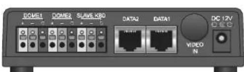
text_image
DOME1 DOME2 SLAVE KB0 DATA2 DATA1 DC 12V VIDEO N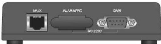
text_image
MUX ALARM/PG DVR RS-232CFigure -Front & Rear
NOTE: This junction box is not included in the keyboard box.
NOTE: Don't supply the power to the keyboard and the junction box together.
When you use the junction box with the keyboard, connect the power adaptor of the keyboard to the junction box.
Appendix D -SPECIFICATION
| GENERAL | |
| Certification | CE EMC, FCC CLASS A |
| ELECTRICAL | |
| LCD | 16 X 2 Line LCD |
| Joystick | Zoom handle Joystick |
| Input Voltage | 12 VDC |
| Power Consumption | 6W |
| Communications | RS-485/232 baud rate: 2400 ~38400 bps (default:9600bps) |
| Dome1 Port (RS-485) | Up to 127 dome cameras including 32 Alarm mode on. |
| Dome2 Port (RS-485) | Up to 127 dome cameras including 32 Alarm mode on / SLAVE KEYBOARD / DVR/MULTIPLEXER |
| RS-232 | DVR / UPGRADE |
| MECHANICAL | |
| Dimension | 15.9 X6.9 X 4.2(Unit : inch) : 405x176x107(Unit : mm) |
| Unit Weight | Approx 1.2 kg |
| Shipping Weight | Approx 2.2 kg |
| Shipping Size | 19.7 X9.1 X 6.3(Unit : inch) : 500 x 230 x 160 mm |
| ENVIRONMENT | |
| Operating temperature | 0°C to 50°C (32°F to 122°F) |
| Operating humidity | 0 to 90%RH (non-condensing) |
| Storage temperature | -20°C to 60°C (-4°F to 140°F) |
Specifications are subject to change without notice.

text_image
Technical line drawing of a control panel with labeled dimensions and component layoutsFigure – Dimension
Keyboard Controller
natural_image
Black and white industrial control console with joystick and keyboard (no visible text or symbols)Instruction
MANUAL