
KPC-WDR7000NU - Security Camera KT&C - Free user manual and instructions
Find the device manual for free KPC-WDR7000NU KT&C in PDF.


| Product Type | Security Camera |
| Brand | KT&C |
| Model | KPC-WDR7000NU |
| Dimensions (W x H x D) | 2.9 x 2.7 x 2.2 inches (74 x 68 x 56 mm) |
| Weight | 1.1 lbs (500 g) |
| Power Supply | DC 12V or PoE (IEEE 802.3af) |
| Resolution | 2 MP (1920 x 1080) at 30 fps |
| Lens | 2.8 – 12 mm varifocal, F1.4 |
| Wide Dynamic Range | True WDR (120 dB) |
| Night Vision | IR LEDs up to 100 ft (30 m) |
| Day/Night Function | Mechanical IR cut filter |
| Video Compression | H.265 / H.264 / MJPEG |
| Ingress Protection | IP66 (outdoor rated) |
| Operating Temperature | -40°F to 140°F (-40°C to 60°C) |
| Maintenance | Clean lens with a soft, dry cloth; avoid harsh chemicals |
| Safety Instructions | Use only specified power adapter; do not expose to rain |
| Spare Parts & Repairability | Contact KT&C support for replacement parts or service |
| Warranty | 2 years limited |
Frequently Asked Questions - KPC-WDR7000NU KT&C
User questions about KPC-WDR7000NU KT&C
0 question about this device. Answer the ones you know or ask your own.
Ask a new question about this device
Download the instructions for your Security Camera in PDF format for free! Find your manual KPC-WDR7000NU - KT&C and take your electronic device back in hand. On this page are published all the documents necessary for the use of your device. KPC-WDR7000NU by KT&C.
USER MANUAL KPC-WDR7000NU KT&C
HIGH RESOLUTION WDR COLOR CAMERA
OPERATION MANUAL

natural_image
Exterior view of a metallic industrial sensor or camera module with black lens and wiring (no visible text or symbols)Thank you for choosing our high quality camera. Before attempting to connect or operate, please read and follow these instructions.
- CAUTIONS
- FEATURES
- COMPONENTS
- NAME AND FUNCTION
- INSTALLATION
- DIMENSIONS
- SPECIFICATION
-
OSD MANUAL
-
CAUTIONS
- FEATURES
- COMPONENTS
- NAME AND FUNCTION
- INSTALLATION
- DIMENSIONS
- SPECIFICATION
- OSD MANUAL
This device complies with Part 15 of the FCC Rules. Operation is subject to the following two conditions;
- This device may not cause harmful interference.
- This device must accept any interference received, including interference that may cause undesired operation.
Note
This equipment has been tested and found to comply with the limits for a Class A digital device, pursuant to part 15 of the FCC Rules. These limits are designed to provide reasonable protection against harmful interference when the equipment is operated in a commercial environment. This equipment generates, uses, and can radiate radio frequency energy and, if not installed and used in accordance with the instruction manual, may cause harmful interference to radio communications. Operation of this equipment in a residential area is likely to cause harmful interference in which case the user will be required to correct the interference at his own expense."
WARNING
This is a class A product. In a domestic environment this product may cause radio interference in which case the user may be required to take adequate measures.
Caution
Any changes or modifications in construction of this device which are not expressly approved by the party responsible for compliance could void the user's authority to operate the equipment.
CAUTION
- A regulated DC12V 500mA power supply is recommended for use with this camera for the best picture and the most stable operation.
An unregulated power supply can cause damage to the camera.
When unregulated power supply is applied, product warranty will be out of subject. - It is recommended that the camera is used with a monitor that has a CCTV quality 75 video impedance level.
If your monitor is switched to high impedance then please adjust accordingly. - Do not attempt to disassemble the camera to gain access to the internal components. Refer servicing to your dealer.
- Never face the camera towards the sun or any bright or reflective light, which may cause smear on the picture and possible damage to the CCD.
- Do not remove the serial sticker for the warranty service.
- Do not expose the camera to rain or other types of liquid.
- The apparatus must be connected to a mains socket-outlet with a protective earthing connection.

Correct Disposal of This Product (Waste Electrical & Electronic Equipment)
(Applicable in the European Union and other European countries with separate collection systems)
This marking shown on the product or its literature, indicate that it should not be disposed with other household wastes at the end of its working life. To prevent possible harm to the environment or human health from uncontrolled waste disposal, please separate this from other types of wastes and recycle it responsibly to promote the sustainable reuse of material resources.
This product should not be mixed with other commercial wastes purchased this product, or their local government office, for details of where and how they can take item for environmentally safe recycling.
Business users should contact their supplier and check the terms and conditions of the purchase contract.
Household users should contact either the retailer where they for disposal.

CAUTION
RISK OF ELECTRIC SHOCK DO NOT OPEN

CAUTION: TO REDUCE THE RISK OF ELECTRIC SHOCK, DO NOT REMOVE COVER (OR BACK). NO USER.SERVICEABLE PARTS INSIDE. REFER SERVICING TO QUALIFIED SERVICE PERSONNEL.
This symbol is intended to alert the user to the presence of uninsulated "dangerous voltage" within the product's enclosure that may be of sufficient magnitude to constitute a risk of electric shock to persons.

This symbol is intended to alert the user to the presence of important operating and maintenance(servicing) instructions in the literature accompanying the appliance
• 1/3"960H SONY Double Scan Super HAD CCD II
• High Resolution of 700TV Lines
• WDR (Wide Dynamic Range)
- OSD Function
• Multi Language
(English / Chinese / Russian / Spanish / German)
• Digital slow shutter
• 3DNR
• Privacy Zone 15Zone
- 3x Digital Zoom
- Motion Detect, Face Detection
• DC12V, DC12V / AC24V Dual Voltage
• RS-485 Communication
• True Day & Night With ICR Mechanism
How WDR makes better image?
WDR allows every detail to be captured accurately even if one portion is bright while other portions are dark.


natural_image
Black-and-white photo of people interacting indoors, no visible text or symbols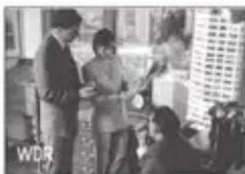
natural_image
Black-and-white photo of people interacting indoors, no visible text or symbols| HIGH PERFORMANCEWDR COLOR CAMERA |  |
| AUTO IRIS LENSCONNECTION PLUG |  |
| C-MOUNT ADAPTOR RING |  |
| OPERATION MANUAL |  |

4. NAME AND FUNCTION
- FRONT
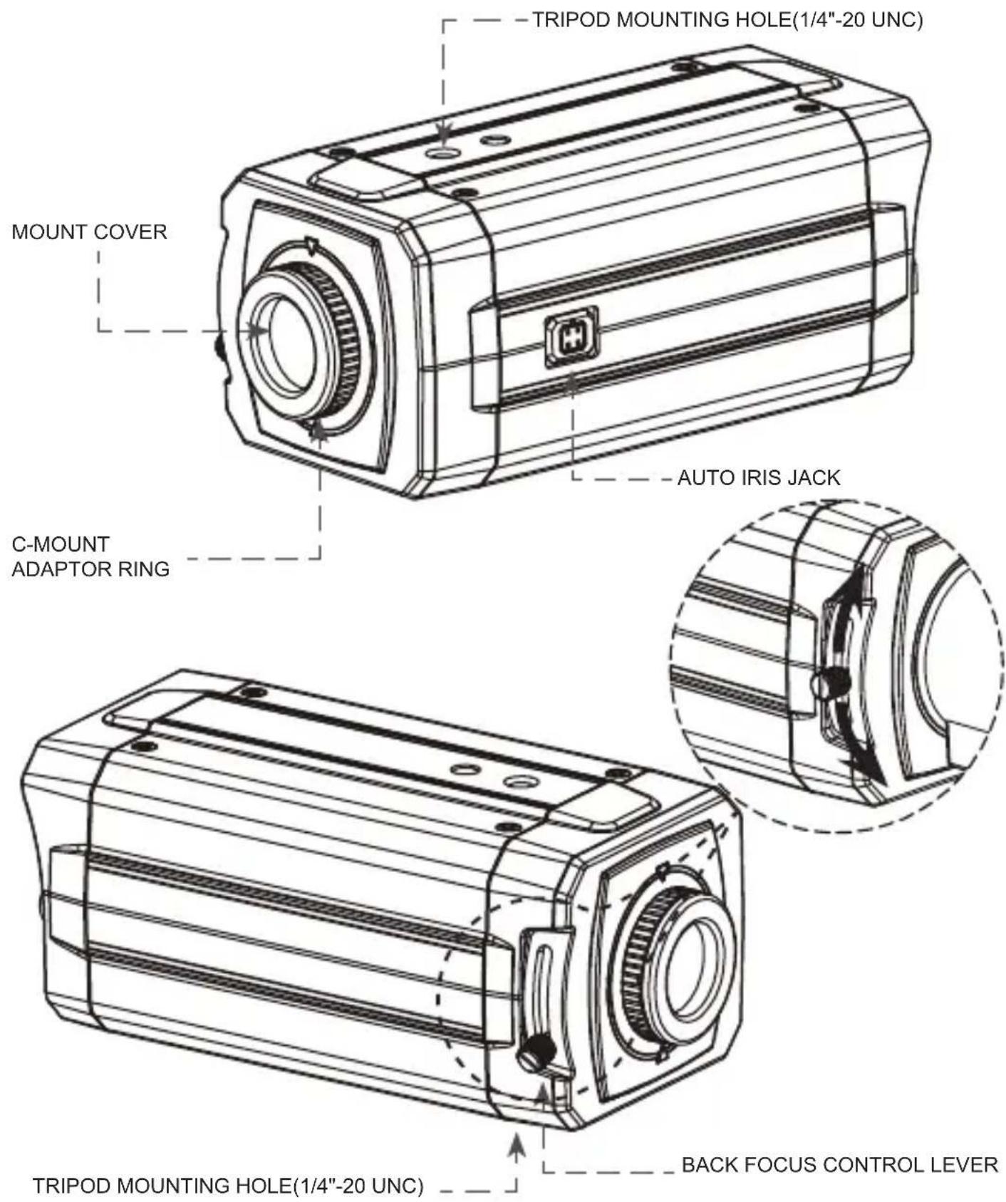
- BACK

DC12V

DC12V/AC24V
①. MENU BUTTON
②. UP BUTTON
③. DOWON BUTTON
④. LEFT BUTTON
⑤. RIGHT BUTTON
⑥. POWER LED
(The LED turns on when power is supplied)
⑦. VIDEO OUT JACK
(Used to connect an external video monitor in jack)
⑧. POWER TERMINAL
(User to connect an DC12V power source)
(Options : AC 24V/DC12V power source)
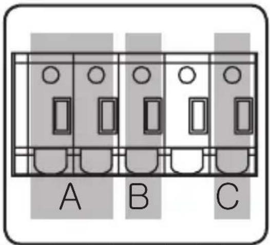
⑨. EXTERNAL CONTROL CONNECTOR
EXTERNAL CONTROL CONNECTOR

A - The camera can be controlled by using external controller such as the keyboard controller. (RS-485 Communication)
B - Motion detection feature is to generate an alarm whenever movement occurs in the video. When Motion Mode is set "ON" on the OSD menu of the camera.
-> Normal status : 0V
-> Motion detected : 3.3V
C - It can be switched to DAY mode or NIGHT mode by receiving the signal from external light sensor or IR LED LAMP.
-> When +3.3V is applied, camera will be switched to BW mode.
-> When 0V is applied, camera will be switched to COLOR mode
CAUTION: Do not apply higher than 3.3V to D/N connector in order to prevent damage to the camera.
5. INSTALLATION
- LENS CONNECTION
Lenses are sold separately. Lenses such as an auto iris lens,
CS-Mount lens and C-Mount lens can be used.
NOTE
- Please keep the lens clean.
- Any foreign objects and Finger marks on the lens can cause inferior image quality in low light level conditions.
When using an auto iris lens
- Please peel off about 8mm of the outer skin of the auto iris lens cable.

- Please peel off about 2mm of the outer skin of the insulated conductor inside the lens cable.
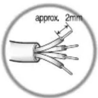
- Please remove the cover of the auto iris lens connection plug and solder the lens cable to the connector pin in the plug.
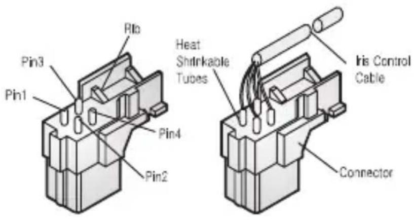
* PIN ASSIGNMENT OF THE LENS CONNECTOR
1) Video auto iris lens
Pin 1: Power source(DC 12V)
Pin 2: N.C(Not used)
Pin 3: Video signal
Pin 4: Shield, GND(Ground)
- Please replace the auto iris lens connection plug cover and take off the Sensor protection cap and then attach the auto iris lens to the camera by screwing it in clockwise.
5. INSTALLATION
- Please insert the connection plug that is connected to the auto iris lens cable into the auto lens connector, which is located on the side of the camera

natural_image
Technical line drawing of a mechanical device with attached pipe and housing (no text or symbols)\* NOTE
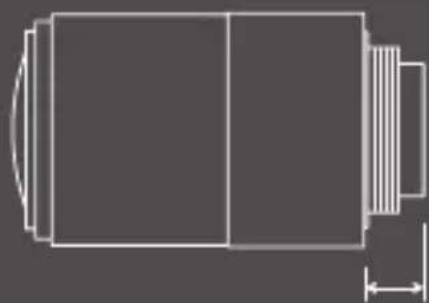
Use the lens under the specification as shown. Otherwise the lens can damage the camera or abnormal fixing may result.

natural_image
Pure technical line drawing of a mechanical component with no text or symbolsC-mount lens : 10mm or less
CS-mount lens : 5mm or less
Installation of C-Mount Lens

Installation of CS-Mount Lens

natural_image
Technical line drawing of a mechanical component with a circular inset showing rotational motion (no text or symbols)5. INSTALLATION
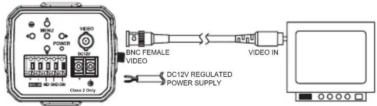
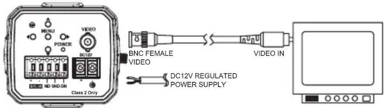
• MONITOR CONNECTION
(1) DC12V
(2) DC12V/AC24V
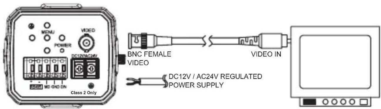
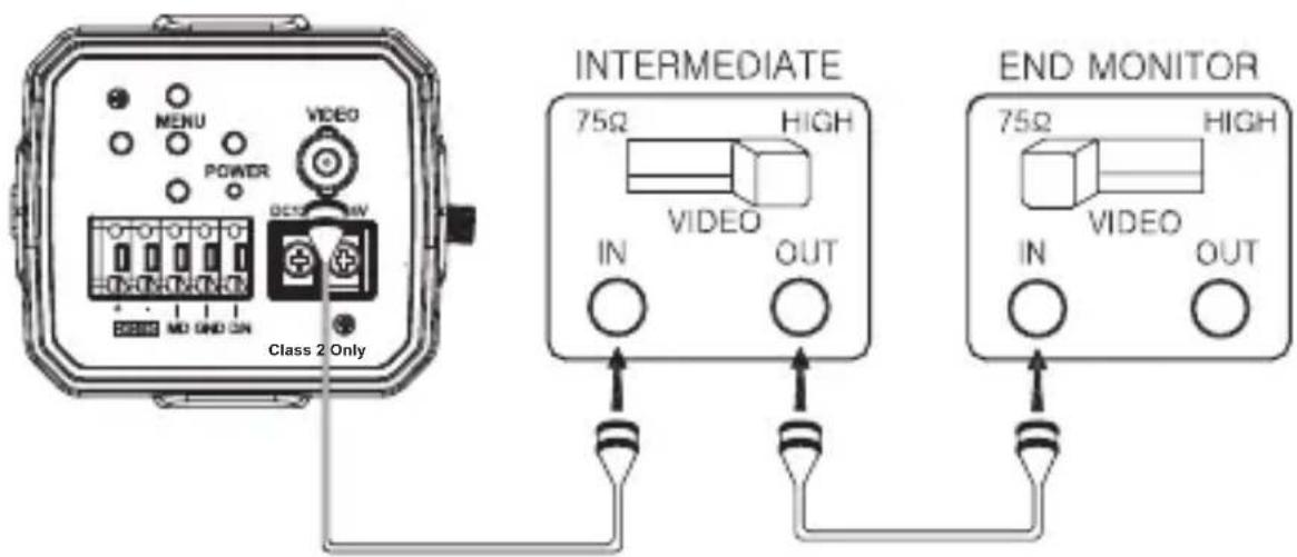
* As the connecting method varies with instruments, refer to the manual supplied with the instrument.
* Only connect the cable when the power is turned off.
* Set the 75Ω / Hi-Z selection switch as shown below if you have an intermediate device
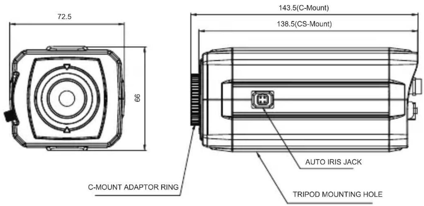
Unit(mm)


- SPECIFICATION
| Signal Format NTSC PAL | |||
| Image Device 1/3" 960H SONY Double Scan Super HAD CCD II | |||
| Scanning System 2:1 Interlace | |||
| H.Resolution 750TV Lines | |||
| Scanning Frequency H:15.734KHz, V:59.94Hz H:15.625KHz, V:50Hz | |||
| Total Pixels 1028(H) X 508(V) 1028(H) X 596(V) | |||
| Effective Pixels 976(H) X 494(V) 976(H) X 582(V) | |||
| Electronic Shutter 1/60 ~1/100,000sec 1/50 ~1/100,000sec | |||
| Digital Zoom Ratio 3x | |||
| Digital Slow Shutter | OFF, 2 ~ 128 Field | ||
| Flickerless | ON / OFF | ||
| WDR | ON / OFF (Level adjustable) | ||
| BLC | ON / OFF (Level adjustment, Area selection) | ||
| 3DNR ON / OFF (Level adjustable) | |||
| Image Function | Image reverse(NORMAL/H / V / HV), Freeze | ||
| Sharpness | Level adjustable | ||
| AGC | LOW / MID / HIGH | ||
| Day & Night | True Day & Night with ICR Mechanism (COLOR / BW / AUTO / EXT) | ||
| Motion Detection | ON / OFF (Level adjustable, Area adjustment) | ||
| Face Detection | ON / OFF (Level adjustable, Area adjustment) | ||
| Privacy Masking | 15 Zones (Area adjustment) | ||
| White Balance | ATW / PUSH / PUSH LOCK / MANUAL(R Gain, B Gain) | ||
| OSD | Built in | ||
| Language | English / Chinese / Russian / Spanish / German | ||
| Protocol | Pelco"D" | ||
| Baud Rate | 2400 / 4800 / 9600 / 19200 | ||
| S/N Ratio | More than 50dB(3DNR ON) | ||
| Gamma | r=0.45 | ||
| Min. Illumination 0.08Lux(Color) / 0.04Lux(BW) (30IRE@F1.4, AGC:HIGH) | |||
| Sync System | Internal | ||
| Video Output | 1.0 Vp-p Composite 75(Ω) unbalanced | ||
| Lens | C / CS (DC\VIDEO) | ||
| Power Consumption | DC12V | DC 12V ±10%, Max 210mA | |
| DUAL | DC 12V ±10%, Max 270mA / AC 24V ±10%, Max 3.9W | ||
| Operating Temperature | 14°F~122°F(-10°C~+50°C) | ||
| Storage Temperature | -4°F~140°F(-20°C~+60°C) | ||
| Humidity | Less than 80% | ||
| External Control | RS485 Communication | ||
| Weight | 400g | ||
| Dimensions(mm) | 72.5mm x 66mm x 138.5mm | ||
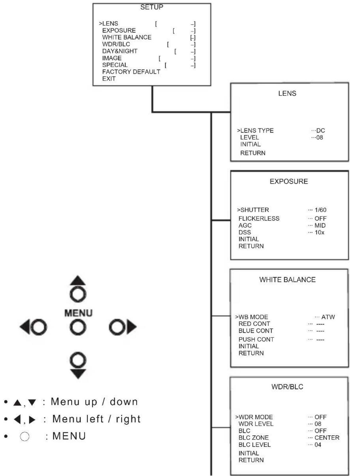
GENERAL STRUCTURE
flowchart
graph TD
    A["SETUP"] --> B["LENS"]
    A --> C["EXPOSURE"]
    A --> D["WHITE BALANCE"]
    A --> E["WDR/BLC"]
    B --> F["LENS TYPE ...DC LEVEL ...08 INITIAL RETURN"]
    C --> G[">SHUTTER ... 1/60 FLICKERLESS ... OFF AGC ... MID DSS ... 10x INITIAL RETURN"]
    D --> H["WHITE BALANCE"]
    E --> I["WDR/BLC"]
    J["MENU"] --> K["▲,▼ : Menu up / down"]
    J --> L["◀,► : Menu left / right"]
    J --> M["○ : MENU"]

flowchart
graph TD
    A["DAY & NIGHT"] --> B["CAM TITLE"]
    B --> C["123456789 ABCDEFGHIJKLMN OPQRSTUVWXYZ!?*#$%()<>{} SPACE>> <<BACK LOCATION ... [+"] RETURN]
    A --> D["IMAGE"]
    D --> E["REVERSE NORMAL DNR ... OFF DNR LEVEL ... 4 SHARPNESS ... 10 FREEZE ... OFF D-ZOOM ... 1.0x INITIAL RETURN"]
    A --> F["SPECIAL"]
    F --> G["MOTION DET"]
    G --> H[">CAM ID ... 0 MASK ... OFF V START ... 07 V END ... 12 H START ... 10 H END ... 19 TOP ANGLE ... 00 BOTTOM ANGLE ... 00 INITIAL RETURN"]
    G --> I["MOTION DET"]
    I --> J[">MOTION MODE ... ON LEVEL ... 08 FACE MODE ... ON LEVEL ... 07 V START ... 01 V END ... 06 H START ... 01 H END ... 10 INITIAL RETURN"]
    I --> K["DISPLAY"]
    K --> L[">CAM ID ... OFF CAM TITLE ... OFF MOTION DETECT ... OFF FACE DETECT ... OFF INITIAL RETURN"]
LENS MENU STRUCTURE

flowchart
graph TD
    A["LENS"] --> B["LENS TYPE"]
    B --> C["ELC"]
    C --> D["DC"]
    D --> E["VIDEO"]
    A --> F["EXPOSURE"]
    F --> G["WHITE BALANCE"]
    G --> H["WDR / BLC"]
    H --> I["DAY&NIGHT"]
    I --> J["IMAGE"]
    J --> K["SPECIAL"]
    K --> L["FACTORY DEFAULT"]
    L --> M["EXIT"]
    B --> N["LEVEL"]
    N --> O["INITIAL"]
    O --> P["RETURN"]
    N --> Q["UP"]
    Q --> R["DOWN (0~15)"]
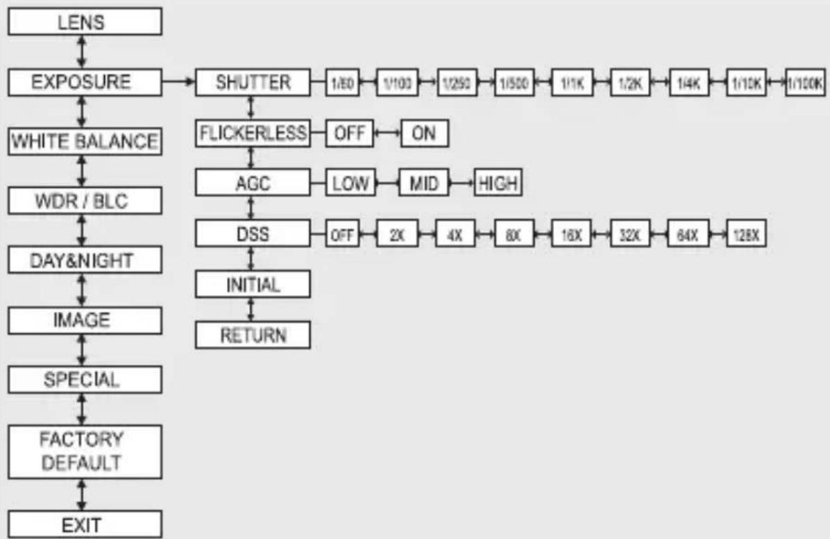
EXPOSURE MENU STRUCTURE
flowchart
graph TD
    A["LENS"] --> B["EXPOSURE"]
    B --> C["SHUTTER"]
    C --> D["1/EO"]
    D --> E["1/100"]
    E --> F["1/250"]
    F --> G["1/500"]
    G --> H["1/1K"]
    H --> I["1/2K"]
    I --> J["1/4K"]
    J --> K["1/10K"]
    K --> L["1/100K"]
    B --> M["WHITE BALANCE"]
    M --> N["WDR / BLC"]
    N --> O["DAY&NIGHT"]
    O --> P["IMAGE"]
    P --> Q["SPECIAL"]
    Q --> R["FACTORY DEFAULT"]
    R --> S["EXIT"]
    C --> T["FLICKERLESS"]
    T --> U["OFF"]
    U --> V["ON"]
    T --> W["AGC"]
    W --> X["LOW"]
    X --> Y["MID"]
    Y --> Z["HIGH"]
    T --> AA["DSS"]
    AA --> AB["OFF"]
    AB --> AC["2X"]
    AC --> AD["4X"]
    AD --> AE["8X"]
    AE --> AF["16X"]
    AF --> AG["32X"]
    AG --> AH["64X"]
    AH --> AI["128X"]
    AA --> AJ["INITIAL"]
    AJ --> AK["RETURN"]
WHITE BALANCE MENU STRUCTURE

flowchart
graph TD
    A["LENS"] --> B["EXPOSURE"]
    B --> C["WHITE BALANCE"]
    C --> D["WB MODE"]
    D --> E["ATW"]
    E --> F["PUSH"]
    F --> G["PUSH LOCK"]
    G --> H["MANUAL"]
    C --> I["WDR / BLC"]
    I --> J["DAY&NIGHT"]
    J --> K["IMAGE"]
    K --> L["SPECIAL"]
    L --> M["FACTORY DEFAULT"]
    M --> N["EXIT"]
    D --> O["RED CONT"]
    O --> P["UP"]
    P --> Q["DOWN (0~255)"]
    J --> R["BLUE CONT"]
    R --> S["UP"]
    S --> T["DOWN (0~255)"]
    J --> U["PUSH AUTO"]
    U --> V["PUSH BUTTON"]
    U --> W["INITIAL"]
    W --> X["RETURN"]
WDR MENU STRUCTURE

flowchart
graph TD
    A["LENS"] --> B["EXPOSURE"]
    B --> C["WHITE BALANCE"]
    C --> D["WDR / BLC"]
    D --> E["DAY&NIGHT"]
    E --> F["IMAGE"]
    F --> G["SPECIAL"]
    G --> H["FACTORY DEFAULT"]
    H --> I["EXIT"]

    J["WDR"] --> K["OFF"] --> L["ON"]
    M["WDR LEVEL"] --> N["UP"] --> O["DOWN (0-15)"]
    P["BLC"] --> Q["OFF"] --> R["ON"]
    S["BLC ZONE"] --> T["TOP"] --> U["BOTTOM"] --> V["CENTER"] --> W["LEFT"] --> X["RIGHT"]
    Y["BLC LEVEL"] --> Z["UP"] --> AA["DOWN (0-15)"]
    AB["INITIAL"] --> AC["RETURN"]

    style J fill:#f9f,stroke:#333
    style M fill:#f9f,stroke:#333
    style P fill:#f9f,stroke:#333
    style S fill:#f9f,stroke:#333
    style Y fill:#f9f,stroke:#333
    style X fill:#f9f,stroke:#333
: Enable user to select the lens type according to equipped with camera. Set up using LEFT, RIGHT KEY at each menu.

- LENS TYPE
①ELC : Enable user to set up for BOARD lens.
②DC : Enable user to set up for DC Iris lens.
③VIDEO : Enable user to set up for VIDEO Iris lens.
- LEVEL
: Enable user to select the level for Brightness of image(0\~15).
- INITIAL
: Enable user to initialize the LENS menu set up.
2. EXPOSURE
: Enable user to set up the function of SHUTTER, FLICKERLESS, AGC, DSS. Set up using LEFT, RIGHT KEY at each menu.

- SHUTTER
: Enable user to set up the Shutter Speed -> 1/60(50), 1/100(120), 1/250, 1/500, 1/1K, 1/2K, 1/4K, 1/10K, 1/100K *() is for PAL TYPE
- FLICKERLESS
: Enable user to set up the FLICKERLESS ON/OFF.
- AGC
: Enable user to make image bright to amplify the Gain. -> LOW, MID, HIGH
- DSS(Digital Slow Shutter)
: Enable user to enhance video quality in extreme low-light condition to slow down the shutter speed and collect over multiple fields based on the shutter limit setting. -> OFF, 2X, 4X, 8X, 16X, 32X, 64X, 128X
- INITIAL
: Enable user to initialize the Exposure menu set up.
3. WHITE BALANCE
: Enable user to represent the accurate white color by controlling the R,G,B level. Setting up LEFT, RIGHT KEY on each menu.

- WB MODE
① ATW : Enable user to trace the White Balance automatically in the range of 2,300K\~10,000K.
② PUSH : Enable user to search for White Balance automatically. In this mode, color temperature range is broader than ATW.
③ PUSH LOCK : Enable user to fix the White Balance according to the color temperature in the certain environment.
④ MANUAL : Enable user to sets the White Balance according to the circumstance.
- RED CONT :
In the USER setting of WB MODE, enable user to set the RED GAIN.
- BLUE CONT :
In the USER setting of WB MODE, enable user to set the BLUE GAIN.
- PUSH AUTO :
In the PUSH LOCK setting of WB MODE, enable user to fix the White Balance in camera setting.
- INITIAL : Enable user to reset the WHITE BALANCE menu setting.
4. WDR/BLC
: Use the condition which Image doesn't figure out with BLC such as place surrounded windows and lobby. Set the WDR using the LEFT, RIGHT KEY on the each menu.
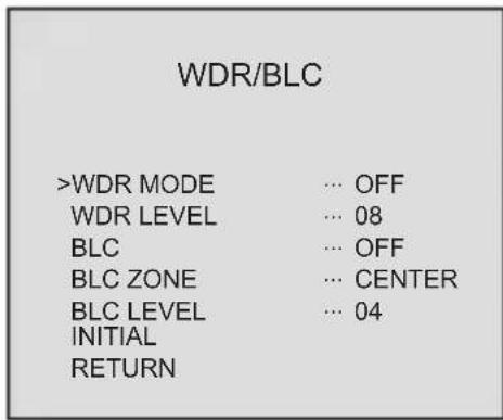
- WDR MODE
① OFF : None WDR
② ON : WDR Fixed
- WDR LEVEL
: Enable user to set WDR Level(0\~15 level).
- BLC(Back Light Compensation)
: Back Light Compensation
- BLC ZONE : Enable user to set the BLC area. TOP, BOTTOM, CENTER, LEFT, RIGHT
- BLC LEVEL : Enable user to set BLC in selected area(0\~15 level).
- INITIAL : Enable user to initialize the WDR setting.
| TOP | ||
| LEFT | CENTER | RIGHT |
| BOTTOM | ||
5. DAY&NIGHT
: Conversion of output image COLOR / BW depending on exterior environment Enable user to set the LEFT, RIGHT KEY in menu.
DAY & NIGHT
| >D&N MODE | ... COLOR |
| DWELL TIME | ... ---- |
| D -> N LEVEL | ... ---- |
| N -> D LEVEL | ... ---- |
| INITIALRETURN |
- D&N MODE
①COLOR : Enable user to fix the output image in color.
②B/W : Enable user to fix the output image in B/W.
③AUTO : Enable user to convert to COLOR/BW automatically by luminace element on Screen.
④EXT : Enable user to convert to COLOR/BW by signal of the exterior input.
-> Low input signal : COLOR
-> High input signal : BW
- DWELL TIME : In D&N MODE AUTO, enable user to set to delay time for changing COLOR/BW (0\~10sec).
- D->N LEVEL : Day(Color) to Night(BW), level(0\~19).
- N->D LEVEL : Night(BW) to Day, level(1\~20).
- INITIAL : Enable user to initialize the setting in DAY&NIGHT menu.
6. IMAGE
: REVERSE, DNR, SHARPNESS, FREEZE, D-ZOOM functions set up by pressing LEFT, RIGHT KEY.

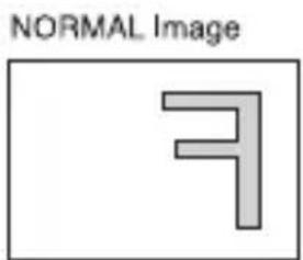
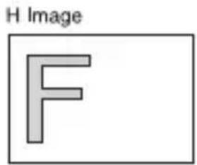
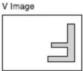
- REVERSE: Enable user to reverse the image. -> NORMAL, H, V, H/V
natural_image
Simple geometric shape resembling a right-angle bracket inside a rectangle labeled 'V Image' (no text or symbols within the shape)
- DNR : Reduces noise by using time-based filtering.
- DNR LEVEL : Enable user to set level(0\~15 steps).
- SHARPNESS : Enable user to control the image sharpness (0\~15steps).
- FREEZE : Enable user to freeze the image.
- D-ZOOM(Digital Zoom) -> Max. 3x Digital Zoom.
- INITIAL : Enable user to initialize the setting on IMAGE menu.
7. SPECIAL
: Setting up the CAM TITLE, LANGUAGE, COMM ADJ, PRIVACY, MOTION DET, DISPLAY Set up using LEFT and RIGHT key in each manual.
SPECIAL
>CAM TITLE ... [-]
LANGUAGE ... ENGLISH
COMM ADJ ... [-]
PRIVACY ... [-]
MOTION DETECT ... [-]
DISPLAY ... [-]
INITIAL
RETURN
- CAM TITLE :
Enable user to choose any word in screen.(Maximum 10 letter is available)
CAM TITLE
0123456789ABCDEFGHIJKLMNOPQRSTUVWXYZ!?*#$%()<>{}
SPACE>> <<BACK
LOCATION ... [-]
RETURN
① A letter Choice from the screen using Menu key.
② Enable user to move to next menu using LEFT, RIGHT KEY in LOCATION.
③ By using UP, DOWN, LEFT, RIGHT KEY, enable user to choose any letters in LOCATION and then get back to previous step.
④ Enable user to finish words choice and position by using LEFT, RIGHT KEY in RETURN.
[TITLE LOCATION]
TITLE
[U] [D] [L][R][M]+
- LANGUAGE : Enable user to set up an OSD language. -> ENGLISH, CHINESE, RUSSIAN, SPANISH, GERMAN
- COMM ADJ : Enable user to set up CAMERA ID, BAUDRATE.

① CAM ID : Enable user to set up Camera ID (0\~255).
② BAUDRATE : A communication speed to Communicate with external device. (2400, 4800, 9600, 19200).
- PRIVACY : Privacy is the function that covers some part on screen to prevent private life (Maximum 15 point covered).
| PRIVACY | |
| >ZONE NO | ... 0 |
| MASK | ... OFF |
| V START ... 07 | |
| V END ... 12 | |
| H START ... 10 | |
| H END ... 19 | |
| TOP ANGLE ... 00 | |
| BOTTOM ANGLE ... 00 | |
| INITIAL | |
| RETURN | |
① ZONE : Enable user to set up positions from 0 to 14.
② MASK : Enable user to set up screen output of chosen position.
③ V START : Mask Vertical start position.
④ V END : Mask Vertical end position.
⑤ H START : Mask Horizontal start position.
⑥ H END : Mask Horizontal end position.
⑦ TOP ANGLE : Top angle position.
⑧ BOTTOM ANGLE : Bottom angle position.
⑨ INITIAL : Enable user to initialize setting of PRIVACY MENU.
- MOTION DET : Motion detection and Face detection function.
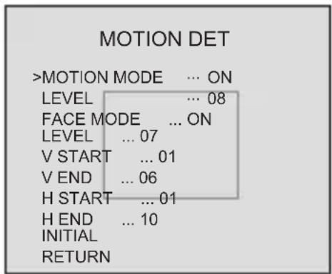
① MOTION MODE : Enable user to set up ON/OFF.
② LEVEL : Enable user to setup a motion detect sensitivity (0\~15).
③ FACE MODE : Enable user to set up ON/OFF.
④ LEVEL : Enable user to set up a face detect sensitivity (0\~15).
⑤ V START : Mask Vertical start position.
⑥ V END : Mask Vertical end position.
⑦ H START : Mask Horizontal start position.
⑧ H END : Mask Horizontal end position.
⑨ INITIAL : Enable user to initialize setting of MOTION DETECT.
- DISPLAY : Enable user to set up a screen marking of CAM ID, CAM TITLE, MOTION, FACE
① CAM ID : Enable user to set up output on Camera ID screen.
② CAM TITLE : Enable user to set up output in fixed CAM TITLE.
③ MOTION DETECT : Enable user to set up output of MOTION on the screen as MOTION DET ON setting.
③ FACE DETECT : Enable user to set up out put of FACE on the screen as FACE DETECT ON setting.
④ INITIAL : Enable user to initialize of DISPLAY menu.
- FACTORY DEFAULT
: Enable user to reset all of the status as the factory default Setting up using LEFT, RIGHT KEY.
- EXIT
: Enable user to EXIT the OSD menu Setting up using LEFT, RIGHT KEY.
DISPLAY
| >CAM ID | ... OFF |
| CAM TITLE | ... OFF |
| MOTION DETECT | ... OFF |
| FACE DETECT | ... OFF |
| INITIAL | |
| RETURN |
Pelco "D" Protocol Commands
- Most widely used Commands

※ MENU① : Pelco Keyboard Menu On/Off [95(=0x5F) + Pattern]
※ MENU② : V/D Keyboard Menu On/Off [ Set Preset + 98(=0x62) ]
※ MENU③④ : Another Menu On/Off [ Go To Preset + 95(=0x5F) or 96(=0x60 ]
※ CamID : 0x00 \~ 0xFF ※ ChkSum : The Check Sum is the 8 bit (modulo256) sum of the payload bytes (BYTE2-BYTE6) in the command.
- TELE = UP KEY
- WIDE = DOWN KEY
- NEAR = LEFT KEY
- FAR = RIGHT KEY
- MENU = MENU KEY
This device complies with Part 15 of the FCC Rules. Operation is subject to the following two conditions;
- This device may not cause harmful interference.
- This device must accept any interference received, including interference that may cause undesired operation.
Note
This equipment has been tested and found to comply with the limits for a Class A digital device, pursuant to part 15 of the FCC Rules. These limits are designed to provide reasonable protection against harmful interference when the equipment is operated in a commercial environment. This equipment generates, uses, and can radiate radio frequency energy and, if not installed and used in accordance with the instruction manual, may cause harmful interference to radio communications. Operation of this equipment in a residential area is likely to cause harmful interference in which case the user will be required to correct the interference at his own expense."
WARNING
This is a class A product. In a domestic environment this product may cause radio interference in which case the user may be required to take adequate measures.
Caution
Any changes or modifications in construction of this device which are not expressly approved by the party responsible for compliance could void the user's authority to operate the equipment.
CAUTION
- A regulated DC12V 500mA power supply is recommended for use with this camera for the best picture and the most stable operation.
An unregulated power supply can cause damage to the camera.
When unregulated power supply is applied, product warranty will be out of subject. - It is recommended that the camera is used with a monitor that has a CCTV quality 75 video impedance level.
If your monitor is switched to high impedance then please adjust accordingly. - Do not attempt to disassemble the camera to gain access to the internal components. Refer servicing to your dealer.
- Never face the camera towards the sun or any bright or reflective light, which may cause smear on the picture and possible damage to the CCD.
- Do not remove the serial sticker for the warranty service.
- Do not expose the camera to rain or other types of liquid.
- The apparatus must be connected to a mains socket-outlet with a protective earthing connection.
Correct Disposal of This Product (Waste Electrical & Electronic Equipment)
(Applicable in the European Union and other European countries with separate collection systems)
This marking shown on the product or its literature, indicate that it should not be disposed with other household wastes at the end of its working life. To prevent possible harm to the environment or human health from uncontrolled waste disposal, please separate this from other types of wastes and recycle it responsibly to promote the sustainable reuse of material resources.
This product should not be mixed with other commercial wastes purchased this product, or their local government office, for details of where and how they can take item for environmentally safe recycling.
Business users should contact their supplier and check the terms and conditions of the purchase contract.
Household users should contact either the retailer where they for disposal.

CAUTION
RISK OF ELECTRIC SHOCK DO NOT OPEN

CAUTION: TO REDUCE THE RISK OF ELECTRIC SHOCK, DO NOT REMOVE COVER (OR BACK). NO USER.SERVICEABLE PARTS INSIDE. REFER SERVICING TO QUALIFIED SERVICE PERSONNEL.

This symbol is intended to alert the user to the presence of uninsulated "dangerous voltage" within the product's enclosure that may be of sufficient magnitude to constitute a risk of electric shock to persons.

This symbol is intended to alert the user to the presence of important operating and maintenance(servicing) instructions in the literature accompanying the appliance
• 1/3"960H SONY Double Scan Super HAD CCD II
• High Resolution of 700TV Lines
• WDR (Wide Dynamic Range)
- OSD Function
• Multi Language
(English / Chinese / Russian / Spanish / German)
• Digital slow shutter
• 3DNR
• Privacy Zone 15Zone
• 3x Digital Zoom
- Motion Detect, Face Detection
• DC12V, DC12V / AC24V Dual Voltage
• RS-485 Communication
• True Day & Night With ICR Mechanism
How WDR makes better image?
WDR allows every detail to be captured accurately even if one portion is bright while other portions are dark.


natural_image
Black-and-white photo of people interacting indoors, no visible text or symbols
natural_image
Black-and-white photo of people interacting indoors, no visible text or symbols| HIGH PERFORMANCEWDR COLOR CAMERA | |
| AUTO IRIS LENSCONNECTION PLUG | |
| C-MOUNT ADAPTOR RING | |
| OPERATION MANUAL |  |

4. NAME AND FUNCTION
- FRONT
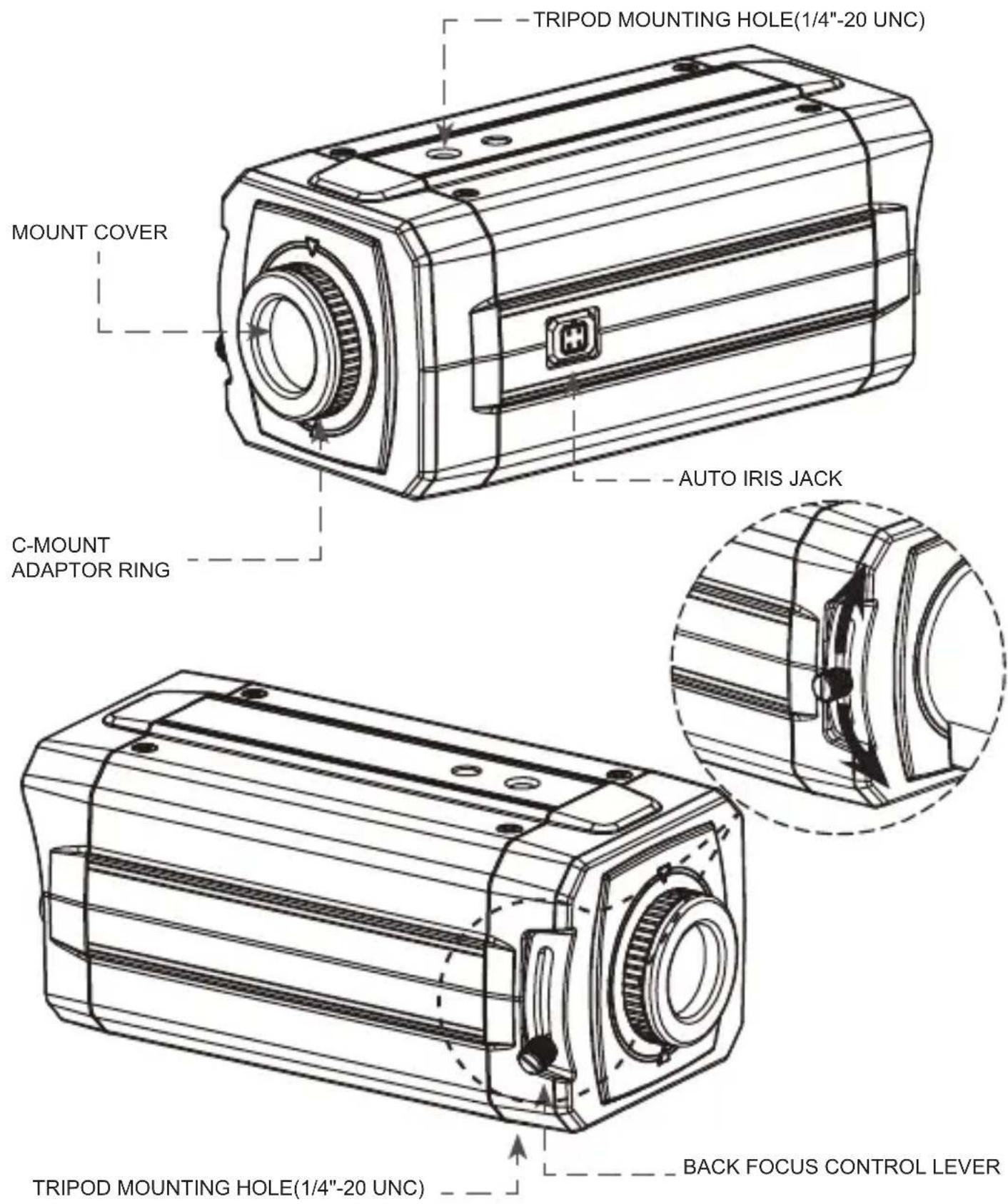
- BACK
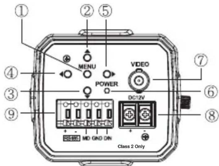
DC12V

DC12V/AC24V
①. MENU BUTTON
②. UP BUTTON
③. DOWON BUTTON
④. LEFT BUTTON
⑤. RIGHT BUTTON
⑥. POWER LED
(The LED turns on when power is supplied)
⑦. VIDEO OUT JACK
(Used to connect an external video monitor in jack)
⑧. POWER TERMINAL
(User to connect an DC12V power source)
(Options : AC 24V/DC12V power source)
⑨. EXTERNAL CONTROL CONNECTOR
EXTERNAL CONTROL CONNECTOR
A - The camera can be controlled by using external controller such as the keyboard controller. (RS-485 Communication)
B - Motion detection feature is to generate an alarm whenever movement occurs in the video. When Motion Mode is set "ON" on the OSD menu of the camera.
-> Normal status : 0V
-> Motion detected : 3.3V
C - It can be switched to DAY mode or NIGHT mode by receiving the signal from external light sensor or IR LED LAMP.
-> When +3.3V is applied, camera will be switched to BW mode.
-> When 0V is applied, camera will be switched to COLOR mode
CAUTION: Do not apply higher than 3.3V to D/N connector in order to prevent damage to the camera.
5. INSTALLATION
- LENS CONNECTION
Lenses are sold separately. Lenses such as an auto iris lens,
CS-Mount lens and C-Mount lens can be used.
NOTE
- Please keep the lens clean.
- Any foreign objects and Finger marks on the lens can cause inferior image quality in low light level conditions.
When using an auto iris lens
- Please peel off about 8mm of the outer skin of the auto iris lens cable.

- Please peel off about 2mm of the outer skin of the insulated conductor inside the lens cable.

- Please remove the cover of the auto iris lens connection plug and solder the lens cable to the connector pin in the plug.

* PIN ASSIGNMENT OF THE LENS CONNECTOR
1) Video auto iris lens
Pin 1: Power source(DC 12V)
Pin 2: N.C(Not used)
Pin 3: Video signal
Pin 4: Shield, GND(Ground)
- Please replace the auto iris lens connection plug cover and take off the Sensor protection cap and then attach the auto iris lens to the camera by screwing it in clockwise.
5. INSTALLATION
- Please insert the connection plug that is connected to the auto iris lens cable into the auto lens connector, which is located on the side of the camera

natural_image
Technical line drawing of a mechanical device with attached pipe and housing (no text or symbols)\* NOTE
Use the lens under the specification as shown. Otherwise the lens can damage the camera or abnormal fixing may result.
natural_image
Pure technical line drawing of a mechanical component with no text or symbolsC-mount lens : 10mm or less
CS-mount lens : 5mm or less
Installation of C-Mount Lens

Installation of CS-Mount Lens

natural_image
Technical line drawing of a mechanical component with a circular inset showing rotational motion (no text or symbols)5. INSTALLATION
• MONITOR CONNECTION
(1) DC12V
(2) DC12V/AC24V

* As the connecting method varies with instruments, refer to the manual supplied with the instrument.
* Only connect the cable when the power is turned off.
* Set the 75Ω / Hi-Z selection switch as shown below if you have an intermediate device

Unit(mm)

- SPECIFICATION
| Signal Format NTSC PAL | |||
| Image Device 1/3" 960H SONY Double Scan Super HAD CCD II | |||
| Scanning System 2:1 Interlace | |||
| H.Resolution 750TV Lines | |||
| Scanning Frequency H:15.734KHz, V:59.94Hz H:15.625KHz, V:50Hz | |||
| Total Pixels 1028(H) X 508(V) 1028(H) X 596(V) | |||
| Effective Pixels 976(H) X 494(V) 976(H) X 582(V) | |||
| Electronic Shutter 1/60 ~1/100,000sec 1/50 ~1/100,000sec | |||
| Digital Zoom Ratio 3x | |||
| Digital Slow Shutter | OFF, 2 ~ 128 Field | ||
| Flickerless | ON / OFF | ||
| WDR | ON / OFF (Level adjustable) | ||
| BLC | ON / OFF (Level adjustment, Area selection) | ||
| 3DNR ON / OFF (Level adjustable) | |||
| Image Function | Image reverse(NORMAL/H / V / HV), Freeze | ||
| Sharpness | Level adjustable | ||
| AGC | LOW / MID / HIGH | ||
| Day & Night | True Day & Night with ICR Mechanism (COLOR / BW / AUTO / EXT) | ||
| Motion Detection | ON / OFF (Level adjustable, Area adjustment) | ||
| Face Detection | ON / OFF (Level adjustable, Area adjustment) | ||
| Privacy Masking | 15 Zones (Area adjustment) | ||
| White Balance | ATW / PUSH / PUSH LOCK / MANUAL(R Gain, B Gain) | ||
| OSD | Built in | ||
| Language | English / Chinese / Russian / Spanish / German | ||
| Protocol | Pelco"D" | ||
| Baud Rate | 2400 / 4800 / 9600 / 19200 | ||
| S/N Ratio | More than 50dB(3DNR ON) | ||
| Gamma | r=0.45 | ||
| Min. Illumination 0.08Lux(Color) / 0.04Lux(BW) (30IRE@F1.4, AGC:HIGH) | |||
| Sync System | Internal | ||
| Video Output | 1.0 Vp-p Composite 75(Ω) unbalanced | ||
| Lens | C / CS (DC\VIDEO) | ||
| Power Consumption | DC12V | DC 12V ±10%, Max 210mA | |
| DUAL | DC 12V ±10%, Max 270mA / AC 24V ±10%, Max 3.9W | ||
| Operating Temperature | 14°F~122°F(-10°C~+50°C) | ||
| Storage Temperature | -4°F~140°F(-20°C~+60°C) | ||
| Humidity | Less than 80% | ||
| External Control | RS485 Communication | ||
| Weight | 400g | ||
| Dimensions(mm) | 72.5mm x 66mm x 138.5mm | ||
GENERAL STRUCTURE
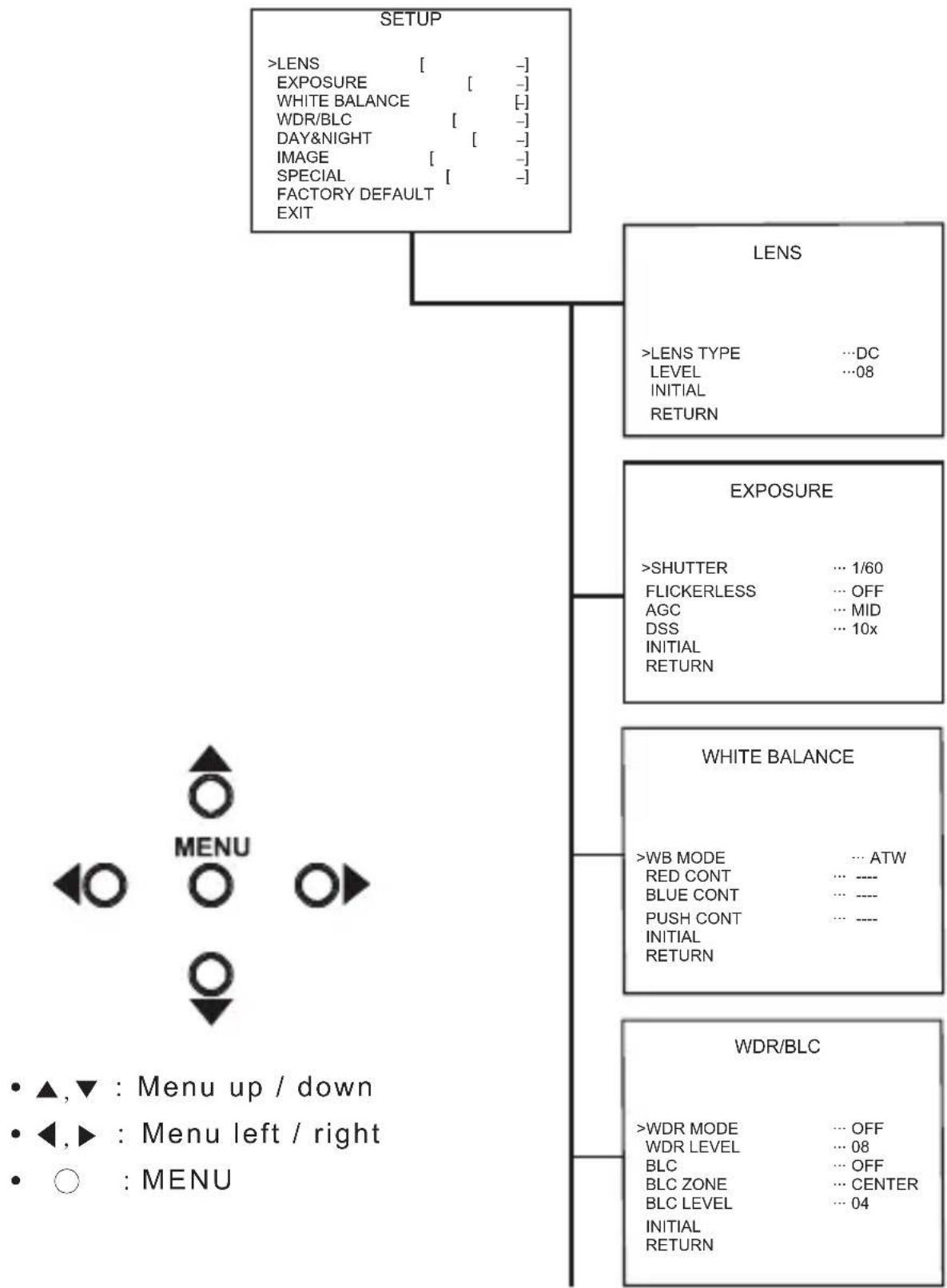
flowchart
graph TD
    A["SETUP"] --> B["LENS"]
    A --> C["EXPOSURE"]
    A --> D["WHITE BALANCE"]
    A --> E["WDR/BLC"]
    B --> F["LENS TYPE ...DC LEVEL ...08 INITIAL RETURN"]
    C --> G[">SHUTTER ... 1/60 FLICKERLESS ... OFF AGC ... MID DSS ... 10x INITIAL RETURN"]
    D --> H["WHITE BALANCE"]
    E --> I["WDR/BLC"]
    J["MENU"] --> K["▲,▼ : Menu up / down"]
    J --> L["◀,▶ : Menu left / right"]
    J --> M["○ : MENU"]

flowchart
graph TD
    A["DAY & NIGHT"] --> B["CAM TITLE"]
    B --> C["123456789 ABCDEFGHIJKLMN OPQRSTUVWXYZ!?*#$%()<>{} SPACE>> <<BACK LOCATION ... [+"] RETURN]
    A --> D["IMAGE"]
    D --> E["REVERSE NORMAL DNR ... OFF DNR LEVEL ... 4 SHARPNESS ... 10 FREEZE ... OFF D-ZOOM ... 1.0x INITIAL RETURN"]
    A --> F["SPECIAL"]
    F --> G["MOTION DET"]
    G --> H[">CAM ID ... 0 MASK ... OFF V START ... 07 V END ... 12 H START ... 10 H END ... 19 TOP ANGLE ... 00 BOTTOM ANGLE ... 00 INITIAL RETURN"]
    G --> I["MOTION DET"]
    I --> J[">MOTION MODE ... ON LEVEL ... 08 FACE MODE ... ON LEVEL ... 07 V START ... 01 V END ... 06 H START ... 01 H END ... 10 INITIAL RETURN"]
    I --> K["DISPLAY"]
    K --> L[">CAM ID ... OFF CAM TITLE ... OFF MOTION DETECT ... OFF FACE DETECT ... OFF INITIAL RETURN"]
LENS MENU STRUCTURE

flowchart
graph TD
    A["LENS"] --> B["LENS TYPE"]
    B --> C["ELC"]
    C --> D["DC"]
    D --> E["VIDEO"]
    A --> F["EXPOSURE"]
    F --> G["WHITE BALANCE"]
    G --> H["WDR / BLC"]
    H --> I["DAY&NIGHT"]
    I --> J["IMAGE"]
    J --> K["SPECIAL"]
    K --> L["FACTORY DEFAULT"]
    L --> M["EXIT"]
    B --> N["LEVEL"]
    N --> O["INITIAL"]
    O --> P["RETURN"]
    N --> Q["UP"]
    Q --> R["DOWN (0~15)"]
EXPOSURE MENU STRUCTURE

flowchart
graph TD
    A["LENS"] --> B["EXPOSURE"]
    B --> C["SHUTTER"]
    C --> D["1/EO"]
    D --> E["1/100"]
    E --> F["1/250"]
    F --> G["1/500"]
    G --> H["1/1K"]
    H --> I["1/2K"]
    I --> J["1/4K"]
    J --> K["1/10K"]
    K --> L["1/100K"]
    B --> M["WHITE BALANCE"]
    M --> N["WDR / BLC"]
    N --> O["DAY&NIGHT"]
    O --> P["IMAGE"]
    P --> Q["SPECIAL"]
    Q --> R["FACTORY DEFAULT"]
    R --> S["EXIT"]
    C --> T["FLICKERLESS"]
    T --> U["OFF"]
    U --> V["ON"]
    T --> W["AGC"]
    W --> X["LOW"]
    X --> Y["MID"]
    Y --> Z["HIGH"]
    T --> AA["DSS"]
    AA --> AB["OFF"]
    AB --> AC["2X"]
    AC --> AD["4X"]
    AD --> AE["8X"]
    AE --> AF["16X"]
    AF --> AG["32X"]
    AG --> AH["64X"]
    AH --> AI["128X"]
    AA --> AJ["INITIAL"]
    AJ --> AK["RETURN"]
WHITE BALANCE MENU STRUCTURE

flowchart
graph TD
    A["LENS"] --> B["EXPOSURE"]
    B --> C["WHITE BALANCE"]
    C --> D["WB MODE"]
    D --> E["ATW"]
    E --> F["PUSH"]
    F --> G["PUSH LOCK"]
    G --> H["MANUAL"]
    C --> I["WDR / BLC"]
    I --> J["DAY&NIGHT"]
    J --> K["IMAGE"]
    K --> L["SPECIAL"]
    L --> M["FACTORY DEFAULT"]
    M --> N["EXIT"]
    D --> O["RED CONT"]
    O --> P["UP"]
    P --> Q["DOWN (0~255)"]
    J --> R["BLUE CONT"]
    R --> S["UP"]
    S --> T["DOWN (0~255)"]
    J --> U["PUSH AUTO"]
    U --> V["PUSH BUTTON"]
    U --> W["INITIAL"]
    W --> X["RETURN"]
WDR MENU STRUCTURE

flowchart
graph TD
    A["LENS"] --> B["EXPOSURE"]
    B --> C["WHITE BALANCE"]
    C --> D["WDR / BLC"]
    D --> E["DAY&NIGHT"]
    E --> F["IMAGE"]
    F --> G["SPECIAL"]
    G --> H["FACTORY DEFAULT"]
    H --> I["EXIT"]

    J["WDR"] --> K["OFF"] --> L["ON"]
    M["WDR LEVEL"] --> N["UP"] --> O["DOWN (0-15)"]

    P["BLC"] --> Q["OFF"] --> R["ON"]
    S["BLC ZONE"] --> T["TOP"] --> U["BOTTOM"] --> V["CENTER"] --> W["LEFT"] --> X["RIGHT"]
    Y["BLC LEVEL"] --> Z["UP"] --> AA["DOWN (0-15)"]

    AB["INITIAL"] --> AC["RETURN"]

    AD["EXIT"] --> AE["EXIT"]
: Enable user to select the lens type according to equipped with camera. Set up using LEFT, RIGHT KEY at each menu.

- LENS TYPE
①ELC : Enable user to set up for BOARD lens.
②DC : Enable user to set up for DC Iris lens.
③VIDEO : Enable user to set up for VIDEO Iris lens.
- LEVEL
: Enable user to select the level for Brightness of image(0\~15).
- INITIAL
: Enable user to initialize the LENS menu set up.
2. EXPOSURE
: Enable user to set up the function of SHUTTER, FLICKERLESS, AGC, DSS. Set up using LEFT, RIGHT KEY at each menu.

- SHUTTER
: Enable user to set up the Shutter Speed -> 1/60(50), 1/100(120), 1/250, 1/500, 1/1K, 1/2K, 1/4K, 1/10K, 1/100K *() is for PAL TYPE
- FLICKERLESS
: Enable user to set up the FLICKERLESS ON/OFF.
- AGC
: Enable user to make image bright to amplify the Gain. -> LOW, MID, HIGH
- DSS(Digital Slow Shutter)
: Enable user to enhance video quality in extreme low-light condition to slow down the shutter speed and collect over multiple fields based on the shutter limit setting. -> OFF, 2X, 4X, 8X, 16X, 32X, 64X, 128X
- INITIAL
: Enable user to initialize the Exposure menu set up.
3. WHITE BALANCE
: Enable user to represent the accurate white color by controlling the R,G,B level. Setting up LEFT, RIGHT KEY on each menu.

- WB MODE
① ATW : Enable user to trace the White Balance automatically in the range of 2,300K\~10,000K.
② PUSH : Enable user to search for White Balance automatically. In this mode, color temperature range is broader than ATW.
③ PUSH LOCK : Enable user to fix the White Balance according to the color temperature in the certain environment.
④ MANUAL : Enable user to sets the White Balance according to the circumstance.
- RED CONT :
In the USER setting of WB MODE, enable user to set the RED GAIN.
- BLUE CONT :
In the USER setting of WB MODE, enable user to set the BLUE GAIN.
- PUSH AUTO :
In the PUSH LOCK setting of WB MODE, enable user to fix the White Balance in camera setting.
- INITIAL : Enable user to reset the WHITE BALANCE menu setting.
4. WDR/BLC
: Use the condition which Image doesn't figure out with BLC such as place surrounded windows and lobby. Set the WDR using the LEFT, RIGHT KEY on the each menu.

- WDR MODE
① OFF : None WDR
② ON : WDR Fixed
- WDR LEVEL
: Enable user to set WDR Level(0\~15 level).
- BLC(Back Light Compensation)
: Back Light Compensation
- BLC ZONE : Enable user to set the BLC area. TOP, BOTTOM, CENTER, LEFT, RIGHT
- BLC LEVEL : Enable user to set BLC in selected area(0\~15 level).
- INITIAL : Enable user to initialize the WDR setting.
| TOP | ||
| LEFT | CENTER | RIGHT |
| BOTTOM | ||
5. DAY&NIGHT
: Conversion of output image COLOR / BW depending on exterior environment Enable user to set the LEFT, RIGHT KEY in menu.
DAY & NIGHT
| >D&N MODE | ... COLOR |
| DWELL TIME | ... ---- |
| D -> N LEVEL | ... ---- |
| N -> D LEVEL | ... ---- |
| INITIALRETURN |
- D&N MODE
①COLOR : Enable user to fix the output image in color.
②B/W : Enable user to fix the output image in B/W.
③AUTO : Enable user to convert to COLOR/BW automatically by luminace element on Screen.
④EXT : Enable user to convert to COLOR/BW by signal of the exterior input.
-> Low input signal : COLOR
-> High input signal : BW
- DWELL TIME : In D&N MODE AUTO, enable user to set to delay time for changing COLOR/BW (0\~10sec).
- D->N LEVEL : Day(Color) to Night(BW), level(0\~19).
- N->D LEVEL : Night(BW) to Day, level(1\~20).
- INITIAL : Enable user to initialize the setting in DAY&NIGHT menu.
6. IMAGE
: REVERSE, DNR, SHARPNESS, FREEZE, D-ZOOM functions set up by pressing LEFT, RIGHT KEY.

- REVERSE: Enable user to reverse the image. -> NORMAL, H, V, H/V


natural_image
Simple geometric shape resembling a right-angle bracket inside a rectangle labeled 'V Image' (no text or symbols within the shape)
- DNR : Reduces noise by using time-based filtering.
- DNR LEVEL : Enable user to set level(0\~15 steps).
- SHARPNESS : Enable user to control the image sharpness (0\~15steps).
- FREEZE : Enable user to freeze the image.
- D-ZOOM(Digital Zoom) -> Max. 3x Digital Zoom.
- INITIAL : Enable user to initialize the setting on IMAGE menu.
7. SPECIAL
: Setting up the CAM TITLE, LANGUAGE, COMM ADJ, PRIVACY, MOTION DET, DISPLAY Set up using LEFT and RIGHT key in each manual.
SPECIAL
>CAM TITLE ... [-]
LANGUAGE ... ENGLISH
COMM ADJ ... [-]
PRIVACY ... [-]
MOTION DETECT ... [-]
DISPLAY ... [-]
INITIAL
RETURN
- CAM TITLE :
Enable user to choose any word in screen.(Maximum 10 letter is available)
CAM TITLE
0123456789ABCDEFGHIJKLMNOPQRSTUVWXYZ!?*#$%()<>{}
SPACE>> <<BACK
LOCATION ... [-]
RETURN
① A letter Choice from the screen using Menu key.
② Enable user to move to next menu using LEFT, RIGHT KEY in LOCATION.
③ By using UP, DOWN, LEFT, RIGHT KEY, enable user to choose any letters in LOCATION and then get back to previous step.
④ Enable user to finish words choice and position by using LEFT, RIGHT KEY in RETURN.
[TITLE LOCATION]
TITLE
[U] [D] [L][R][M]+
- LANGUAGE : Enable user to set up an OSD language. -> ENGLISH, CHINESE, RUSSIAN, SPANISH, GERMAN
- COMM ADJ : Enable user to set up CAMERA ID, BAUDRATE.

① CAM ID : Enable user to set up Camera ID (0\~255).
② BAUDRATE : A communication speed to Communicate with external device. (2400, 4800, 9600, 19200).
- PRIVACY : Privacy is the function that covers some part on screen to prevent private life (Maximum 15 point covered).
| PRIVACY | |
| >ZONE NO | ... 0 |
| MASK | ... OFF |
| V START ... 07 | |
| V END ... 12 | |
| H START ... 10 | |
| H END ... 19 | |
| TOP ANGLE ... 00 | |
| BOTTOM ANGLE ... 00 | |
| INITIAL | |
| RETURN | |
① ZONE : Enable user to set up positions from 0 to 14.
② MASK : Enable user to set up screen output of chosen position.
③ V START : Mask Vertical start position.
④ V END : Mask Vertical end position.
⑤ H START : Mask Horizontal start position.
⑥ H END : Mask Horizontal end position.
⑦ TOP ANGLE : Top angle position.
⑧ BOTTOM ANGLE : Bottom angle position.
⑨ INITIAL : Enable user to initialize setting of PRIVACY MENU.
- MOTION DET : Motion detection and Face detection function.

① MOTION MODE : Enable user to set up ON/OFF.
② LEVEL : Enable user to setup a motion detect sensitivity (0\~15).
③ FACE MODE : Enable user to set up ON/OFF.
④ LEVEL : Enable user to set up a face detect sensitivity (0\~15).
⑤ V START : Mask Vertical start position.
⑥ V END : Mask Vertical end position.
⑦ H START : Mask Horizontal start position.
⑧ H END : Mask Horizontal end position.
⑨ INITIAL : Enable user to initialize setting of MOTION DETECT.
- DISPLAY : Enable user to set up a screen marking of CAM ID, CAM TITLE, MOTION, FACE
① CAM ID : Enable user to set up output on Camera ID screen.
② CAM TITLE : Enable user to set up output in fixed CAM TITLE.
③ MOTION DETECT : Enable user to set up output of MOTION on the screen as MOTION DET ON setting.
③ FACE DETECT : Enable user to set up out put of FACE on the screen as FACE DETECT ON setting.
④ INITIAL : Enable user to initialize of DISPLAY menu.
- FACTORY DEFAULT
: Enable user to reset all of the status as the factory default Setting up using LEFT, RIGHT KEY.
- EXIT
: Enable user to EXIT the OSD menu Setting up using LEFT, RIGHT KEY.
DISPLAY
| >CAM ID | ... OFF |
| CAM TITLE | ... OFF |
| MOTION DETECT | ... OFF |
| FACE DETECT | ... OFF |
| INITIAL | |
| RETURN |
Pelco "D" Protocol Commands
- Most widely used Commands

※ MENU① : Pelco Keyboard Menu On/Off [95(=0x5F) + Pattern]
※ MENU② : V/D Keyboard Menu On/Off [ Set Preset + 98(=0x62) ]
※ MENU③④ : Another Menu On/Off [ Go To Preset + 95(=0x5F) or 96(=0x60 ]
※ CamID : 0x00 \~ 0xFF ※ ChkSum : The Check Sum is the 8 bit (modulo256) sum of the payload bytes (BYTE2-BYTE6) in the command.
- TELE = UP KEY
- WIDE = DOWN KEY
- NEAR = LEFT KEY
- FAR = RIGHT KEY
- MENU = MENU KEY
- HIGH RESOLUTION WDR COLOR CAMERA
- This device complies with Part 15 of the FCC Rules. Operation is subject to the following two conditions;
- Note
- WARNING
- Caution
- Correct Disposal of This Product (Waste Electrical & Electronic Equipment)
- How WDR makes better image?
- NAME AND FUNCTION
- INSTALLATION
- - LENS CONNECTION
- When using an auto iris lens
- \* NOTE
- • MONITOR CONNECTION
- - LENS TYPE
- - LEVEL
- - INITIAL
- EXPOSURE
- - SHUTTER
- - FLICKERLESS
- - AGC
- - DSS(Digital Slow Shutter)
- WHITE BALANCE
- - WB MODE
- - RED CONT :
- - BLUE CONT :
- - PUSH AUTO :
- WDR/BLC
- - WDR MODE
- - WDR LEVEL
- - BLC(Back Light Compensation)
- DAY&NIGHT
- - D&N MODE
- IMAGE
- SPECIAL
- - CAM TITLE :
- DISPLAY
- Pelco "D" Protocol Commands
Brand : KT&C
Model : KPC-WDR7000NU
Category : Security Camera