
KPC-HLND45M - Security Camera KT&C - Free user manual and instructions
Find the device manual for free KPC-HLND45M KT&C in PDF.


| Product Type | Security Camera |
| Brand | KT&C |
| Model | KPC-HLND45M |
| Image Sensor | 1/3" 2.1 Megapixel SONY CMOS |
| Effective Pixels | 1984(H) x 1105(V) |
| Minimum Illumination | 0 Lux (IR on) / 0.1 Lux (color) |
| Day/Night | True Day&Night with ICR (Auto/Color/BW) |
| WDR / BLC | WDR, BLC, OFF |
| Lens | Board lens (fixed) |
| IR LED | 850nm, 15 LEDs, 10m range |
| Video Output | HD-SDI (1080p/720p) + CVBS (NTSC/PAL) |
| OSD Control | Built-in joystick |
| Power Supply | DC12V (±10%) or AC24V (±10%), dual model |
| Power Consumption | Max 310mA (DC12V) / 3.5W (AC24V) |
| Dimensions (mm) | Ø120 x 55 |
| Weight | Approx. 350g |
| IP Rating | IP66 |
| Operating Temperature | 14°F ~ 122°F (-10°C ~ +50°C) |
| Storage Temperature | -4°F ~ 140°F (-20°C ~ +60°C) |
| Humidity | Less than 80% |
| Digital Zoom | 1x ~ 20x |
| Shutter Speed | Auto/Manual (1/30 ~ 1/30K sec) |
| AGC | 0 ~ 23dB |
| 3D NR | Off/Low/Middle/High |
| White Balance | Auto/Push Lock/Manual |
| DNR | Yes (3D) |
Frequently Asked Questions - KPC-HLND45M KT&C
User questions about KPC-HLND45M KT&C
0 question about this device. Answer the ones you know or ask your own.
Ask a new question about this device
Download the instructions for your Security Camera in PDF format for free! Find your manual KPC-HLND45M - KT&C and take your electronic device back in hand. On this page are published all the documents necessary for the use of your device. KPC-HLND45M by KT&C.
USER MANUAL KPC-HLND45M KT&C
- CAUTIONS
- IMPORTANT SAFETY INSTRUCTIONS
- EQUIPMENT AND ACCESSORIES
- CAMERA COMPONENT DESCRIPTIONS
- INSTALLATION
- DIMENSIONS
-
SPECIFICATIONS
-
OSD MANUAL
-
Menu Structure
- Function Description
CAUTION
These servicing instructions are for use by qualified service personnel only. To reduce the risk of electric shock do not perform any servicing other than that contained in the operating instructions unless you are qualified to do so.
Use Class 2 Power Supply Only
This device complies with Part 15 of the FCC Rules. Operation is subject to the following two conditions:
- This device may not cause harmful interference.
- This device must accept any interference received, including interference that may cause undesired operation.
Note
This equipment has been tested and found to comply with the limits for a Class A digital device, pursuant to part 15 of the FCC Rules. These limits are designed to provide reasonable protection against harmful interference when the equipment is operated in a commercial environment. This equipment generates, uses, and can radiate radio frequency energy and, if not installed and used in accordance with the instruction manual, may cause harmful interference to radio communications. Operation of this equipment in a residential area is likely to cause harmful interference in which case the user will be required to correct the interference at his own expense.
WARNING
This is a class A product. In a domestic environment this product may cause radio interference in which case the user may be required to take adequate measures.
Caution
Any changes or modifications in construction of this devices which are not expressly approved by the party responsible for compliance could void the user's authority to operate the equipment.
CAUTION
- A regulated DC12V 500mA power supply is recommended for use with this camera for the best picture and the most stable operation.
When an unregulated power supply is applied, the product warranty will be roid. - It is recommended that the camera be used with a monitor that has a CCTV quality 75 video impedance level. If your monitor is switched to high impedance then please adjust accordingly.
- Do not attempt to disassemble the camera to gain access to the internal components. Refer servicing to your dealer.
- Never face the camera towards the sun or any bright or reflective light, which may cause smears on the picture and possible damage to the Image Sensor.
- Do not remove the serial sticker for the warranty service.
- Do not expose the camera to rain or other types of liquid.
- The apparatus must be connected to a main socket-outlet with a protective earth connection.

WEEE
(Waste Electrical & Electronic Equipment)
This marking shown on the product or its literature, indicates that it should not be disposed with other household wastes at the end of its working life. To prevent possible harm to the environment or human health from uncontrolled waste disposal, please separate this from other types of wastes and recycle it responsibly to promote the sustainable reuse of material resources. Household users should contact either the retailer where they purchased this product, or their local government office, for details of where and how they can take item for environmentally safe recycling.
Business users should contact their supplier and check the terms and conditions of the purchase contract.
This product should not be mixed with other commercial wastes for disposal.

CAUTION
RISK OF ELECTRIC SHOCK DO NOT OPEN

CAUTION: TO REDUCE THE RISK OF ELECTRIC SHOCK, DO NOT REMOVE COVER (OR BACK). NO USER SERVICEABLE PARTS INSIDE. REFER SERVICING TO QUALIFIED SERVICE PERSONNEL
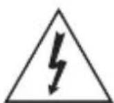
This symbol is intended to alert the user to the presence of un-insulated “dangerous voltage” within the product’s enclosure that may be of sufficient magnitude to constitute a risk of electric shock.

This symbol is intended to alert the user to the presence of important operating and maintenance (servicing) instructions in the literature accompanying the appliance.
2. IMPORTANT SAFETY INSTRUCTION
1) Read these instructions.
2) Keep these instructions.
3) Heed all warnings.
4) Follow all instructions.
5) Do not use this apparatus near water.
6) Clean only with dry cloth.
7) Do not block any ventilation openings. Install in accordance with the manufacturer's instructions.
8) Do not install near any heat sources such as radiators, heat registers, stoves, or other apparatus (including amplifiers) that produce heat.
9) Do not defeat the safety purpose of the polarized or grounding-type plug. A polarized plug has two blades with one wider than the other. A grounding type plug has two blades and a third grounding prong. The wide blade or the third prong are provided for your safety. If the provided plug does not fit into your outlet, consult an electrician for replacement of the obsolete outlet.
10) Protect the power cord from being walked on or pinched particularly at plugs, convenience receptacles, and the point where they exit from the apparatus.
11) Only use attachments/accessories specified by the manufacturer.
12) Use only with the cart, stand, tripod, bracket, or table specified by the manufacturer, or sold with the apparatus. When a cart is used, use caution when moving the cart/apparatus combination to avoid injury from tip-over.
13) Unplug this apparatus during lightning storms or when unused for long periods of time.
14) Refer all servicing to qualified service personnel. Servicing is required when the apparatus has been damaged in any way, such as power-supply cord or plug is damaged, liquid has been spilled or objects have fallen into the apparatus, the apparatus has been exposed to rain or moisture, does not operate normally, or has been dropped.

3. EQUIPMENT AND ACCESSORIES
| Dome Type |
| Mount Guide |
| Manual | |
| Screws(3ea) / L-Wrench Service Video Output Test Cable | |
4. CAMERA COMPONENT DESCRIPTIONS

| NO PART NAME |
| 1 Housing Top |
| 2 Window |
| 3 Cover PCB |
| 4 PCB Module |
| 5 Rubber Case |
| 6 Housing Bottom |
| 7 Holder Middle |
| 8 Holder Top |
| 9 Ball Ass'y |
| 10 Holder Bottom |
| 11 Wave Water |
5. INSTALLATION
- Attach the Camera to the ceiling with using the screws provided, taking into considering the camera angle required for the surveillance function.

- Adjust the LENS ANGLE to the desired location by hand.

CAUTION: With certain wide-angle lenses, the upper part of the image may be obscured when the tilt angle exceeds 80°
CAUTION: panning(Pan + Horizontal) the bracket in excess of 1 rotations in one direction may cause damage to the cable.
5. INSTALLATION
- Connect the VIDEO OUT CABLE and check the video image. Change the SETTINGS accordingly using the OSD controller.

- After the SETTING is completed, install the TOP COVER.

5. INSTALLATION
• MONITOR CONNECTION
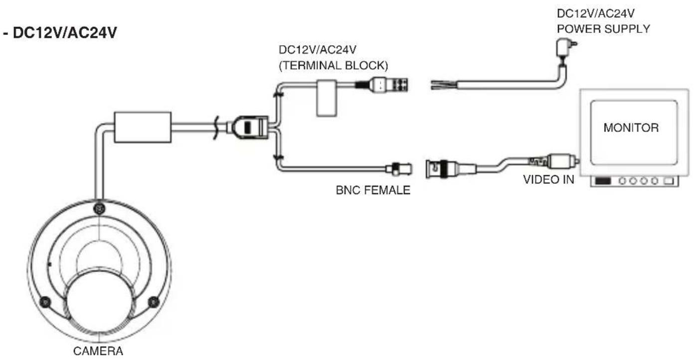
flowchart
graph TD
    A["CAMERA"] --> B["DC12V/AC24V (TERMINAL BLOCK)"]
    B --> C["BNC FEMALE"]
    C --> D["DC12V/AC24V POWER SUPPLY"]
    D --> E["MONITOR"]
    E --> F["VIDEO IN"]
    F --> G["Output"]

flowchart
graph TD
    A["CAMERA"] --> B["DC12V (DC JACK)"]
    B --> C["BNC FEMALE"]
    C --> D["DC12V ADAPTER"]
    D --> E["MONITOR"]
    E --> F["VIDEO IN"]
    F --> G["Monitor"]

When you install the camera, please glue the end of cable to keep it stable in order to protect the camera from humidity problems.
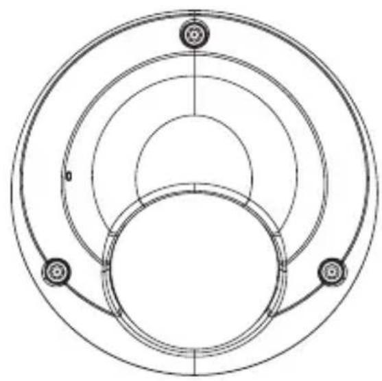
natural_image
Pure technical diagram of concentric circular rings with no text, numbers, or symbols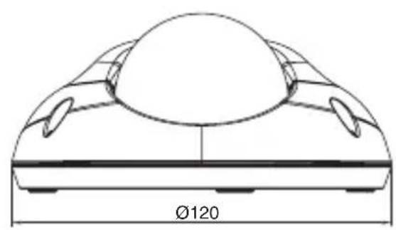
natural_image
Technical line drawing of a mechanical component with a circular top and flanged side (no text or symbols)

natural_image
Technical line drawing of a mechanical component with dimension标注 (no text or symbols)Unit(mm)
- SPECIFICATIONS
| LED Type Standard Type | |||
| Image Sensor 1/3" 2.1 Mega Pixel SONY CMOS | |||
| Effective Pixels 1984(H) x 1105(V) | |||
| Unit cell size 2.8um (H) x 2.8um (V) | |||
| Video output mode | SDI: 1080P 30fps(25fps) / 720P 60fps(50fps) TV Out: CVBS NTSC/PAL | ||
| Minimum Illumination 0 Lux 0.1 Lux | |||
| Shutter speed | Auto / Manual1/30(25),1/60(50),1/120(100),1/250,1/700,1/1K,1/1.6K,1/2.5K,1/5K,1/7K,1/10K,1/30K | ||
| Day/Night | True Day&Night with ICR Mechanism(AUTO/Color/BW) | - | |
| WDR / BLC OFF / WDR / BLC | |||
| AGC 0 ~ 23dB | |||
| 3 DNR OFF / LOW / MIDDLE / HIGHT | |||
| Digital Zoom Ratio 1x ~ 20x | |||
| Digital Slow Shutter OFF, x2, x3, x4, x5, x6, x7, x8 | |||
| White Balance AUTO / PUSH LOCK / Manual | |||
| Lens Board Lens | |||
| OSD Built-in with joystick | |||
| IR - LED 850nm, 15ea, 10m | - | ||
| Operating Temperature | 14°F~122°F(-10°C~+50°C) | ||
| Storage Temperature -4°F~140°F(-20°C~+60°C) | |||
| Humidity | Less than 80% | ||
| Power Consumption | DC | DC12V (±10%), Max. 230mA | DC12V (±10%), Max. 120mA |
| DUAL | DC12V (±10%), Max. 310mA AC24V (±10%), Max. 3.5W | DC12V (±10%), Max. 160mA AC24V (±10%), Max. 2.0W | |
| Dimension (mm) | Ø120mm x 55mm | ||
| Weight | Approx. 350g | ||
| IP Rating | IP 66 | ||
Specifications and designs are subject to change for improving the functionality of this product without notice.
1. EXPOSURE
- BRIGHTNESS:
Enables user to control the image brightness (1\~20steps).
- SHUTTER MODE:
Enables user to set the
Shutter Mode. -> AUTO, MANUAL, FLICKER
- SHUTTER SPEED:
Enables user to set the Shutter Speed.
-> 1/30(25), 1/60(50), 1/120(100), 1/250, 1/700, 1/1K, 1/1.6K, 1/2.5K, 1/5K, 1/7K, 1/10K, 1/30K. ^* () is for "power" and "frequency" 50Hz
- DSS(Digital Slow Shutter): Enables user to set the DSS Level.
-> OFF, X2, X3, X4, X5, X6, X7, X8 - AGC MAX: Enables user to make the imager brighter by amplifying the Gain (0\~23dB).
- INITIAL: Enables user to reset the Exposure menu set up.
EXPOSURE
| > BRIGHRNESS | | | | | | | | 10 |
| SHUTTER MODE | AUTO |
| SHUTTER SPEED | --- |
| DSS | X2 |
| AGC MAX | 18dB |
| INITIAL | |
| RETURN |
2. WHITE BALANCE
Enables user to represent white accurately by controlling the RGB levels.
- WB MODE
- AUTO: Enables user to trace the White Balance automatically in the range of 2,300K\~10,000K.
- PUSH LOCK: Enables user to adjust the White Balance according to the color temperature of the environment.
- MANUAL: Enables user to sets the White Balance according to the circumstance.
- AUTO EXT: Extended auto mode for special illumination.
- CHROMA: Enables user to set the Color Gain(0\~20steps).
- KELVIN: In the MANUAL setting of WB MODE, enables user to set the color temperature range.
- RED GAIN: In the MANUAL setting of WB MODE, enables user to set the RED GAIN.
- BLUE GAIN: In the MANUAL setting of WB MODE, enables user to set the BLUE GAIN.
- PUSH AUTO: In the PUSH LOCK setting of WB MODE, enables user to fix the White Balance in camera setting.
- INITIAL: Enables user to reset the WHITE BALANCE menu setting.
WHITE BALANCE
| > WB MODE | AUTO |
| CHROMA | ||||||||| |
| KELVIN | ---- |
| RED GAIN | ---- |
| BLUE GAIN | ---- |
| PUSH AUTO | ---- |
| INITIAL | |
| RETURN |
3. WDR/BLC
- MODE: Enables user to set WDR/BLC mode.
-> OFF, WDR, BLC
① WDR(Wide Dynamic Range): For use in conditions were BLC is not sufficient to produce a clean image, such as in lobbies and places surrounded by windows.
② BLC(Backlight Compensation):
This function helps make subjects visible in backlit conditions.
- WDR LEVEL: Enables user to set WDR Level (0\~4 level).
- BLC ZONE: Enables user to turn the BLC zone ON/OFF.
- BLC X-POSITION: Enables user to set Vertical start position (0\~20steps).
- BLC Y-POSITION: Enables user to set Horizontal start position (0\~20steps).
- BLC X-SIZE: Enables user to set Vertical size (0\~20steps).
- BLC Y-SIZE: Enables user to set Horizontal size (0\~20steps).
- INITIAL: Enables user to reset the BLC setting.
WDR / BLC
MODE
WDR LEVEL
BLC ZONE
BLC X - POSITION
BLC Y - POSITION
BLC X - SIZE
BLC Y - SIZE
INITIAL
RETURN
BLC
OFF
6
14
7
| : : : : : : | 10
4-1. DAY&NIGHT (LED Type)
Conversion of output image to COLOR / BW depending on exterior environment.
DAY&NIGHT
MODE
DWELL TIME
DAY -> NIGHT
NIGHT -> DAY
IR OPTIMIZER
IR OPT. LEVEL
INITIAL
RETURN
AUTO
3s
| | | | | | | | 1
- COLOR: Enables user to set the image to color mode.
- B/W: Enables user to set the image to B/W mode.
3 AUTO: Enables user to convert to COLOR/BW automatically by photocell
- DWELL TIME: In D&N MODE AUTO, enables user to set a delay when changing COLOR/BW(1\~10sec).
- DAY->NIGHT: Sets threshold for switching from Day to Night.
- NIGHT->DAY: Sets threshold for switching from Night to Day.
- IR OPTIMIZER: Automatically adjusts the image so that the IR LED light close not saturate the screen.
- IR OPT. LEVEL: Enables user to set IR OPTIMIZER level. (0\~15 level)
- INITIAL: Enables user to reset the DAY&NIGHT menu.
4-2. DAY&NIGHT (Standard Type)
Conversion of output image to COLOR / BW depending on exterior environment.
- D&N MODE
- COLOR: Enables user to set the image to color mode.
- B/W: Enables user to set the image to B/W mode.
3 AUTO: Enables user to convert to COLOR/BW automatically by photocell
- DWELL TIME: In D&N MODE AUTO, enables user to set a delay when for changing COLOR/BW(0\~10sec).
- AGC THRS: The threshold AGC value for switching from Day to Night. In D&N MODE AUTO, enables user to set AGC THRESHOLD level (0\~20steps).
- MARGIN: To switch from Day to Night margins. In D&N MODE AUTO, enables user to set to MARGIN level (0\~20steps)
- INITIAL: Enables user to reset the DAY&NIGHT menu.
DAY&NIGHT
MODE
DWELL TIME
AGC THRS
MARGIN
INITIAL
RETURN
AUTO
3s
10
10
- MARGIN: To switch from Day to Night margins. In D&N MODE AUTO, enables user to set to MARGIN level (0\~20steps)
- INITIAL: Enables user to reset the DAY&NIGHT menu.
5. IMAGE
- SHARPNESS: Enables user to control the image sharpness. (0\~10steps).
- FLIP: Sets the Vertical and Horizontal flip for the display output.
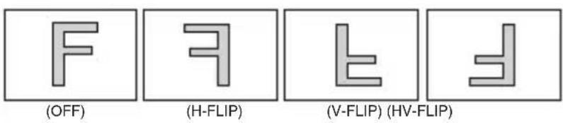
- DZOOM(Digital Zoom): Max. 20x Digital Zoom.
- HLMASK: This function improves the visual recognition of license plates and other such objects by suppressing or masking strong light sources.
-
HLMASK LEVEL: Enables user to set HLMASK Level (0\~20steps).
-
HLMASK COLOR: Set the HLMASK color (Black, White, Yellow, Cyan, Green, Magenta, Red, Blue).
- D-WDR: In this mode, the brightness of a single image is compensated using the gamma curve.
- DNR: This function reduces noise.
IMAGE
SHARPNESS
FLIP
DZOOM
HLMASK
D-WDR
DNR
DEFOG
INITIAL
RETURN
| | | | | | | 8
OFF
1.0X
OFF
OFF
MIDDLE
OFF
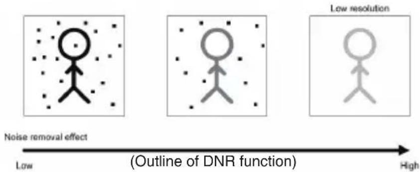
flowchart
graph LR
    A["Noise removal effect"] --> B["Low"]
    C["Low resolution"] --> D["High"]
    style A fill:#f9f,stroke:#333
    style B fill:#ccf,stroke:#333
    style C fill:#cfc,stroke:#333
    style D fill:#fcc,stroke:#333
- DEFOG: Visibility Enhancement for low contrast. Conditions Use this function in foggy weather.
- INITIAL: Enables user to reset the IMAGE menu.
8. OSD MANUAL
6. SPECIAL
: For setting up the CAM TITLE, LANGUAGE, MOTION PRIVACY, DISPLAY, SYSTEM.

- CAM TITLE : Enables user to choose any name for the camera. (10 letter maximum)
- Choose a letter on the screen using the Menu Key
- Move to the next menu by using the LEFT, RIGHT KEY in LOCATION.
-
By using UP, DOWN, LEFT, RIGHT KEY, the user can choose any letter in LOCATION and go back to the previous step.
-
Finish the letter choose and positioning by using LEFT, RIGHT KEY in RRTURN.

SYSTEM
1. DEFECT DET: White pixel detection and compensation function. 2. DOUT FORMAT: Enables user to set digital output format (720p, 1080p). 3. DOUT FPS: Enables user to set digital output frame rate. 4.FREQ: Enables user to set power-frequency(50Hz, 60Hz). 5. CVBS: Enables user to set CVBS type (NTSC or PAL). 6. APPLY: Enable user to apply the SYSTEM settings. MOTION| > RESOLUTION | 1 |
| SENSITIVITY | 10 |
| WINDOW USE | ON |
| WINDOW TONE | 1 |
| X-POSITION | 11 |
| Y-POSITION | 3 |
| X-SIZE | 39 |
| Y-SIZE | 28 |
| INITIAL |
| > CAM TITLE | OFF |
| MOTION | OFF |
| DZOOM | OFF |
| INITIALRETURN |
| > DEFECT DET | [ ] |
| DOUT FORMAT | 1080P |
| DOUT FPS | 30 |
| FREQ | 60HZ |
| CVBS | NTSC |
| APPLY | [ ↓] |
| RETURN |
7. FACTORY DEFAULT
: Enables user to reset all of the settings to the factory default.8. EXIT
: Exits the OSD menu after saving the camera settings.HOT KEY
To quickly switch CVBS type(NTSC or PAL), Push LEFT KEY or RIGHT KEY more than 2 seconds and the push SET KEY.- CAUTION
- This device complies with Part 15 of the FCC Rules. Operation is subject to the following two conditions:
- Note
- WARNING
- WEEE
- (Waste Electrical & Electronic Equipment)
- IMPORTANT SAFETY INSTRUCTION
- EQUIPMENT AND ACCESSORIES
- CAMERA COMPONENT DESCRIPTIONS
- INSTALLATION
- • MONITOR CONNECTION
- EXPOSURE
- - BRIGHTNESS:
- - SHUTTER MODE:
- - SHUTTER SPEED:
- EXPOSURE
- WHITE BALANCE
- - WB MODE
- WHITE BALANCE
- WDR/BLC
- 4-1. DAY&NIGHT (LED Type)
- DAY&NIGHT
- 4-2. DAY&NIGHT (Standard Type)
- - D&N MODE
- IMAGE
- IMAGE
- OSD MANUAL
- SPECIAL
- SYSTEM
- FACTORY DEFAULT
- EXIT
- HOT KEY
Brand : KT&C
Model : KPC-HLND45M
Category : Security Camera