UC-8430-LX - Server Moxa - Free user manual and instructions
Find the device manual for free UC-8430-LX Moxa in PDF.


| Product Type | RISC-based Embedded Computer / Server |
| Brand | Moxa |
| Model | UC-8430-LX |
| CPU | Intel XScale IXP435, 533 MHz |
| Memory | 256 MB DDR2 SDRAM (max. 512 MB), 32 MB NOR Flash, 32 MB NAND Flash |
| Storage Expansion | CompactFlash Socket |
| Operating System | Pre-installed Linux or Windows CE 6.0 |
| Ethernet Ports | 3 x 10/100 Mbps (RJ45) |
| Serial Ports | 8 x RS-232/422/485 (RJ45), software-selectable |
| USB Ports | 6 x USB 2.0 Hosts |
| Digital I/O | 4 Digital Inputs, 4 Digital Outputs (sink type, 200 mA max) |
| Video Output | 2 x VGA (D-sub 15-pin), resolution up to 1024x768 |
| Audio | Line-in / Line-out (SM502 chip) |
| Console Port | RS-232, 4-pin header (TxD, RxD, GND) |
| Power Input | 12 to 48 VDC (3-pin terminal block) |
| Power Consumption | 15 W (310 mA @ 48 VDC, 625 mA @ 24 VDC, 1350 mA @ 12 VDC) |
| Dimensions | 200 x 37 x 120 mm (approximate, similar to UC-8410) |
| Weight | 1 kg |
| Mounting | DIN-Rail or Wall Mounting (kits included) |
| Operating Temperature | Standard: -10 to 60°C; Wide Temp: -40 to 75°C |
| Humidity | 5 to 95% RH (non-condensing) |
| Certifications | CE, FCC Class B, UL/cUL, CCC |
| Warranty | 5 years |
| Maintenance | No special cleaning instructions; keep free of dust and debris |
| Safety | Use only with Listed Power Supply; connect to grounded surface; shield power cord |
| Repairability | Battery replacement by qualified personnel; contact Moxa RMA |
Frequently Asked Questions - UC-8430-LX Moxa
User questions about UC-8430-LX Moxa
0 question about this device. Answer the ones you know or ask your own.
Ask a new question about this device
Download the instructions for your Server in PDF format for free! Find your manual UC-8430-LX - Moxa and take your electronic device back in hand. On this page are published all the documents necessary for the use of your device. UC-8430-LX by Moxa.
USER MANUAL UC-8430-LX Moxa
UC-8410/8416/8418/8430
Hardware User's Manual
Sixth Edition, January 2014
www.moxa.com/product
MOXA®
© 2014 Moxa Inc. All rights reserved.
UC-8410/8416/8418/8430
Hardware User's Manual
The software described in this manual is furnished under a license agreement and may be used only in accordance with the terms of that agreement.
Copyright Notice
© 2014 Moxa Inc. All rights reserved.
Trademarks
The MOXA logo is a registered trademark of Moxa Inc.
All other trademarks or registered marks in this manual belong to their respective manufacturers.
Disclaimer
Information in this document is subject to change without notice and does not represent a commitment on the part of Moxa.
Moxa provides this document as is, without warranty of any kind, either expressed or implied, including, but not limited to, its particular purpose. Moxa reserves the right to make improvements and/or changes to this manual, or to the products and/or the programs described in this manual, at any time.
Information provided in this manual is intended to be accurate and reliable. However, Moxa assumes no responsibility for its use, or for any infringements on the rights of third parties that may result from its use.
This product might include unintentional technical or typographical errors. Changes are periodically made to the information herein to correct such errors, and these changes are incorporated into new editions of the publication.
Technical Support Contact Information
www.moxa.com/support
Moxa Americas
Toll-free: 1-888-669-2872
Tel: +1-714-528-6777
Fax: +1-714-528-6778
Moxa Europe
Tel: +49-89-3 70 03 99-0
Fax: +49-89-3 70 03 99-99
Moxa India
Tel: +91-80-4172-9088
Fax: +91-80-4132-1045
Moxa China (Shanghai office)
Toll-free: 800-820-5036
Tel: +86-21-5258-9955
Fax: +86-21-5258-5505
Moxa Asia-Pacific
2. Appearance and Dimensions 2-1
Appearance....2-2
Dimensions....2-6
Hardware Block Diagrams....2-10
LED Indicators 2-12
Reset Button 2-12
Real Time Clock....2-12
3. Mounting Options.... 3-1
Wall or Cabinet Mounting 3-2
DIN-Rail Mounting 3-2
4. Hardware Connection Description 4-1
Wiring Requirements....4-2
Connecting the Power 4-2
Connecting to VGA Monitors (UC-8430 only) 4-3
Connecting to the Network....4-4
Connecting to a Serial Device 4-4
Connecting to a CAN Device 4-5
Connecting to a Speaker or a Headphone (UC-8430 only) 4-5
Connecting to the Console Port 4-6
CompactFlash....4-7
USB 4-8
DI/DO 4-9
Digital Input Wiring 4-9
Digital Output Wiring 4-9
A. Regulatory Approval Statements...... A-1
Thank you for purchasing the Moxa UC-8410/8416/8418/8430 RISC-based ready-to-run embedded computer.
The UC-8410/8416/8418/8430 feature 8 RS-232/422/485 serial ports, 3 10/100 Mbps Ethernet ports, digital input and digital output channels, switching ports, and CompactFlash and USB ports for adding additional memory. All of these features make the UC-8410/8416/8418/8430 ideal for your embedded applications. Note, too, that the UC-8430 comes with 2 VGA outputs, offering dual display connections for field site monitoring.
This manual introduces the hardware of the UC-8410/8416/8418/8430 embedded computers. After a brief introduction of the hardware features, we focus on installing and configuring the hardware.
The following topics are covered in this chapter:
Overview
□ Package Checklist
□ Product Features
□ Product Hardware Specifications
Overview
The UC-8410/8416/8418/8430 features 8 RS-232/422/485 serial ports, 3 10/100 Mbps Ethernet ports, 4 digital input channels and 4 digital output channels (12 digital input channels and 12 digital output channels for the UC-8418), 8 10/100 Mbps switch ports (UC-8416 only), a CompactFlash slot for flash disk expansion, and 2 USB ports (6 USB ports for UC-8430) for adding additional memory (such as a USB flash drive).
The UC-8410/8416/8418/8430 uses an Intel XScale IXP435 533 MHz RISC CPU. Unlike the X86 CPU, which uses a CISC design, the IXP435's RISC design architecture and modern semiconductor technology provide the UC-8410/8416/8418/8430 with a powerful computing engine and communication functions, but without generating a lot of heat. The built-in 16 MB (32 MB for UC-8430) NOR Flash ROM and 256 MB SDRAM give you enough memory to run your application software directly on the UC-8410/8416/8418/8430. Since the dual LAN ports are built into the IXP435 CPU, the UC-8410/8416/8418/8430 is good solution for network security applications.
Package Checklist
All models of the UC-8410/8416/8418/8430 series are shipped with the following items:
• 1 UC-8410/8416/8418/8430 series embedded computer
- Wall-mounting kit
• DIN-Rail mounting kit
- Quick Installation Guide
- Document & Software CD
• Cross-over Ethernet cable
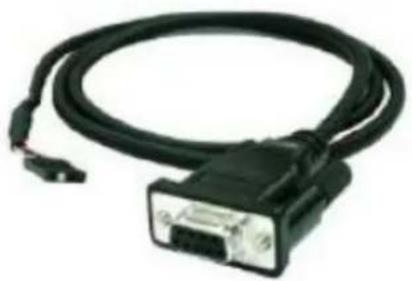
• CBL-4PINDB9F-100: 4-pin pin header to DB9 female console port cable, 100 cm
• Universal power adaptor
• Product Warranty Statement
NOTE: Please notify your sales representative if any of the above items are missing or damaged.
Product Features
• Intel XScale IXP435 533 MHz processor
• On-board 256 MB DDR2 SDRAM (max. 512 MB)
• 16 MB (32 MB for UC-8430) NOR Flash onboard to store OS, 32 MB NAND Flash onboard for data storage
• 8 RS-232/422/485 serial ports
• 4 digital input and 4 digital output channels (12 digital input and 12 digital output channels for UC-8418)
• Dual displays for field site monitoring (UC-8430 only)
• Three 10/100 Mbps Ethernet ports
• 2 USB 2.0 hosts (6 for UC-8430) for mass storage devices
• 8 10/100 Mbps switch ports (UC-8416 only)
• 2 CANbus ports (UC-8418 only)
- CompactFlash socket for storage expansion
• Ready-to-run Linux or Windows CE 6.0 platform
• DIN-Rail or wall mounting installation
- Robust, fanless design
Product Hardware Specifications
Computer
CPU: Intel XScale IXP435, 533 MHz
OS (pre-installed): Linux or Windows CE 6.0
DRAM: 256 MB DDR2 SDRAM onboard (512 MB max.)
SRAM: 256 KB, battery backup
Flash:
• NOR Flash onboard to store OS
UC-8410/8416/8418: 16 MB
UC-8430: 32 MB
• 32 MB NAND Flash onboard to store data
Expansion Bus: PCI/104 onboard
USB: USB 2.0 compliant hosts, type A connector
• UC-8410/8416/8418: 2 hosts
- UC-8430: 6 hosts
Storage
Storage Expansion: CompactFlash socket
Other Peripherals (UC-8430 only)
Audio: SM502 chip with line-in/out interface
Display (UC-8430 only)
Graphics Controller: SM502 chip
Display Interface: 15-pin D-Sub connector x 2
Resolution: CRT display mode with pixel resolution up to 1024 x 768
Ethernet Interface
LAN: 3 auto-sensing 10/100 Mbps ports (RJ45)
Switch Ports: 8 10/100 Mbps unmanaged ports (UC-8416 only)
Magnetic Isolation Protection: 1.5 KV built-in
Serial Interface
Serial Standards: 8 RS-232/422/485 ports, software-selectable (8-pin RJ45)
Console Port: RS-232 (TxD, RxD, GND), 4-pin header output (115200, n, 8, 1)
Serial Communication Parameters
Data Bits: 5, 6, 7, 8
Stop Bits: 1, 1.5, 2
Parity: None, Even, Odd, Space, Mark
Flow Control: RTS/CTS, XON/XOFF, ADDC® (automatic data direction control) for RS-485
Baudrate: 50 bps to 921.6 Kbps (supports non-standard baudrates; see user's manual for details)
Serial Signals
RS-232: TxD, RxD, DTR, DSR, RTS, CTS, DCD, GND
RS-422: TxD+, TxD-, RxD+, RxD-, GND
RS-485-4w: TxD+, TxD-, RxD+, RxD-, GND
RS-485-2w: Data+, Data-, GND
Digital Input
Input Channels: source type
• UC-8410/8416/UC8430: 4 channels
• UC-8418: 12 channels
Input Voltage: 0 to 30 VDC
Digital Input Levels for Dry Contacts:
- Logic level 0: Close to GND
- Logic level 1: Open
Digital Input Levels for Wet Contacts:
- Logic level 0: +3V max.
• Logic level 1: +10V to +30V (COM to DI)
Connector Type: 10-pin screw terminal block (4 points, COM, GND)
Isolation: 3 KV optical isolation
Digital Output
Output Channels: sink type
• UC-8410/8416/UC8430: 4 channels
• UC-8418: 12 channels
Output Current: Max. 200 mA per channel
On-state Voltage: 24 VDC nominal, open collector to 30 V
Connector Type: 10-pin screw terminal block (4 points, GND)
Isolation: 3 KV optical isolation
CANbus Communication (UC-8418 only)
Interface: Dual optically isolated CAN2.0A/2.0B compliant ports
CAN Controller: Phillips SJA1000T
Signals: CAN-H, CAN-L
Isolation: 2 KV digital isolation
Speed: 10 Kbps to 1 Mbps
Connector Type: DB9 male
LEDs
System: Power, Ready, Storage, Battery for SRAM
LAN: 10M/Link x 2, 100M/Link x 2 (on connector)
Serial: TxD x 8, RxD x 8
Reset Button: Supports "Reset to Factory Default"
Physical Characteristics
Housing: SECC sheet metal (1 mm)
Weight: 1 kg
Dimensions:
UC-8410: 200 x 37 x 120 mm (7.87 x 1.46 x 4.72 in)
UC-8416/8418: 200 x 57 x 120 mm (7.87 x 2.24 x 4.72 in)
Mounting: DIN-Rail, wall
Environmental Limits
Operating Temperature:
Standard Models: -10 to 60°C (14 to 140°F)
Wide Temp. Models: -40 to 75°C (-40 to 167°F)
Operating Humidity: 5 to 95% RH
Storage Temperature:
Standard Models: -20 to 75°C (-4 to 167°F)
Wide Temp. Models: -40 to 85°C (-40 to 185°F)
Anti-vibration: 2 g rms @ IEC-68-2-34, random wave, 5-500 Hz, 1 hr per axis
Anti-shock: 20 g @ IEC-68-2-27, half sine wave, 11 ms
Power Requirements
Input Voltage: 12 to 48 VDC (3-pin terminal block)
Power Consumption: 15 W
• 310 mA @ 48 VDC
• 625 mA @ 24 VDC
• 1350 mA @ 12 VDC
Regulatory Approvals
EMC: CE (EN55022 Class B, EN55024-4-2, EN55024-4-3,
EN55024-4-4), FCC (Part 15 Subpart B, Class B)
Safety: UL/cUL (UL60950-1), CCC (GB9254, GB 17625.1), LVD (EN60950)
Reliability
Alert Tools: Built-in buzzer and RTC (real-time clock)
Automatic Reboot Trigger: Built-in WDT (watchdog timer)
Warranty
Warranty Period: 5 years
Details: See www.moxa.com/warranty
Note: The Hardware Specifications apply to the embedded computer unit itself, but not to accessories. In particular, the wide temperature specification does not apply to accessories such as the power adaptor and cables.
The following topics are covered in this chapter:
□ Appearance
Dimensions
□ Hardware Block Diagrams
□ LED Indicators
□ Reset Button
Real Time Clock
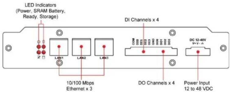
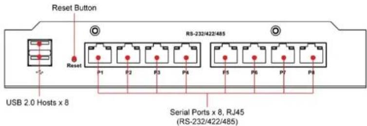
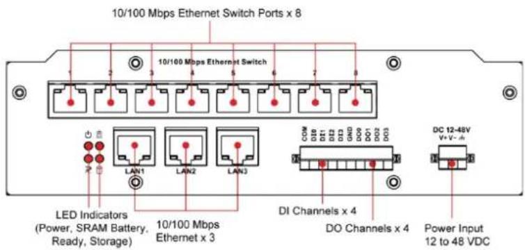
Appearance
UC-8410 Rear View
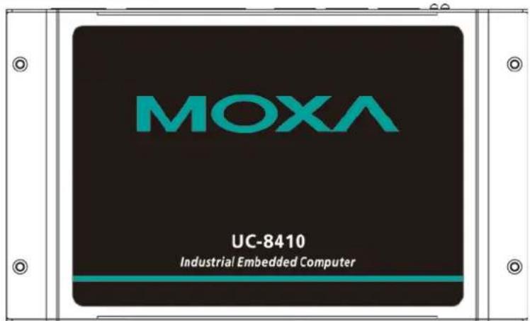
UC-8410 Top View
UC-8410 Front View
UC-8416 Rear View
UC-8416 Top View
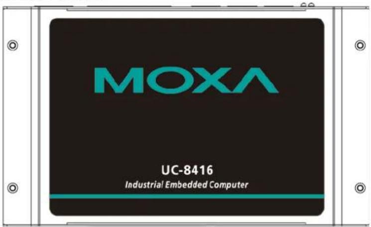
UC-8416 Front View
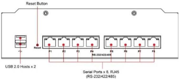
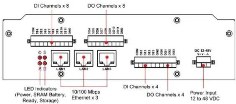
UC-8418 Rear View
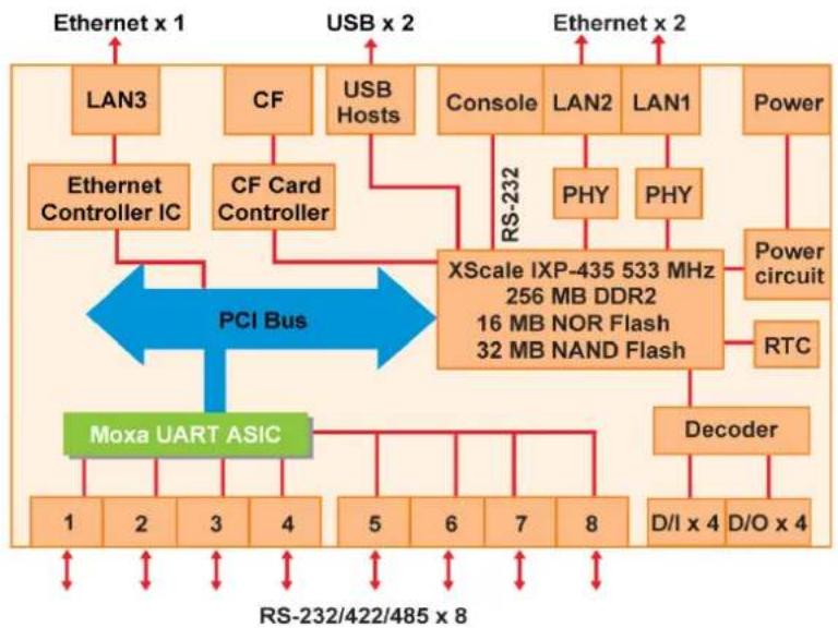
The following block diagram shows the layout of the UC-8410/8416/8418/8430's internal components.
UC-8410
flowchart
graph TD
    subgraph "PCI Bus"
        A["LAN3"] --> B["Ethernet Controller IC"]
        C["CF"] --> D["CF Card Controller"]
        E["USB Hosts"] --> F["Console"]
        G["Power"] --> H["Power circuit"]
        I["XScale IXP-435 533 MHz 256 MB DDR2 16 MB NOR Flash 32 MB NAND Flash"] --> J["RS-232"]
        K["Moxa UART ASIC"] --> L["1 2 3 4 5 6 7 8"]
        M["Decoder"] --> N["D/I x 4 D/O x 4"]
    end
    B <--> F
    D <--> F
    F <--> J
    F <--> K
    style A fill:#f9f,stroke:#333
    style C fill:#f9f,stroke:#333
    style E fill:#f9f,stroke:#333
    style G fill:#f9f,stroke:#333
    style I fill:#f9f,stroke:#333
    style M fill:#f9f,stroke:#333
    style K fill:#f9f,stroke:#333
    style B fill:#ccf,stroke:#333
    style D fill:#ccf,stroke:#333
    style F fill:#ccf,stroke:#333
    style G fill:#ccf,stroke:#333
    style H fill:#ccf,stroke:#333
    style J fill:#ccf,stroke:#333
    style K fill:#ccf,stroke:#333
    style L fill:#ccf,stroke:#333
    style N fill:#ccf,stroke:#333
    style O fill:#ccf,stroke:#333
    style P fill:#ccf,stroke:#333
    style Q fill:#ccf,stroke:#333
    style R fill:#ccf,stroke:#333
    style S fill:#ccf,stroke:#333
    style T fill:#ccf,stroke:#333
    style U fill:#ccf,stroke:#333
    style V fill:#ccf,stroke:#333
    style W fill:#ccf,stroke:#333
    style X fill:#ccf,stroke:#333
    style Y fill:#ccf,stroke:#333
    style Z fill:#ccf,stroke:#333
UC-8416
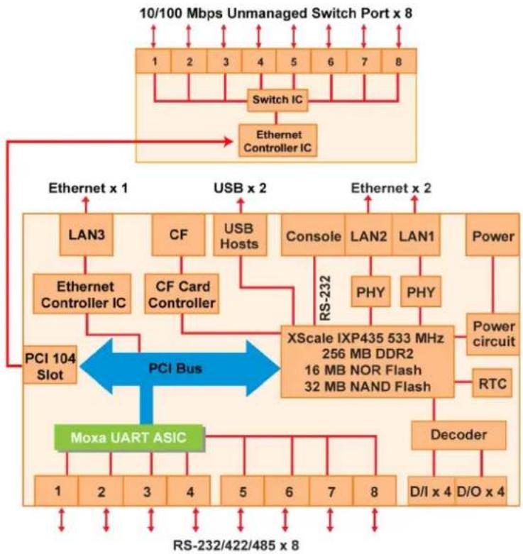
flowchart
graph TD
    A["10/100 Mbps Unmanaged Switch Port x 8"] --> B["Switch IC"]
    B --> C["Ethernet Controller IC"]
    C --> D["PCI Bus"]
    D --> E["PCI 104 Slot"]
    D --> F["Moxa UART ASIC"]
    F --> G["1 2 3 4 5 6 7 8"]
    F --> H["Decoder"]
    H --> I["D/I x 4 D/O x 4"]
    D --> J["RS-232"]
    J --> K["FX Scale IXP435 533 MHz\n256 MB DDR2\n16 MB NOR Flash\n32 MB NAND Flash"]
    K --> L["Power circuit"]
    K --> M["PHY"]
    K --> N["PHY"]
    K --> O["Power"]
    style A fill:#f9f,stroke:#333
    style D fill:#bbf,stroke:#333
    style F fill:#bfb,stroke:#333
    style H fill:#bfb,stroke:#333
    style I fill:#bfb,stroke:#333
    style J fill:#ffb,stroke:#333
    style K fill:#ffb,stroke:#333
    style L fill:#ffb,stroke:#333
    style M fill:#ffb,stroke:#333
    style N fill:#ffb,stroke:#333
    style O fill:#ffb,stroke:#333
UC-8418
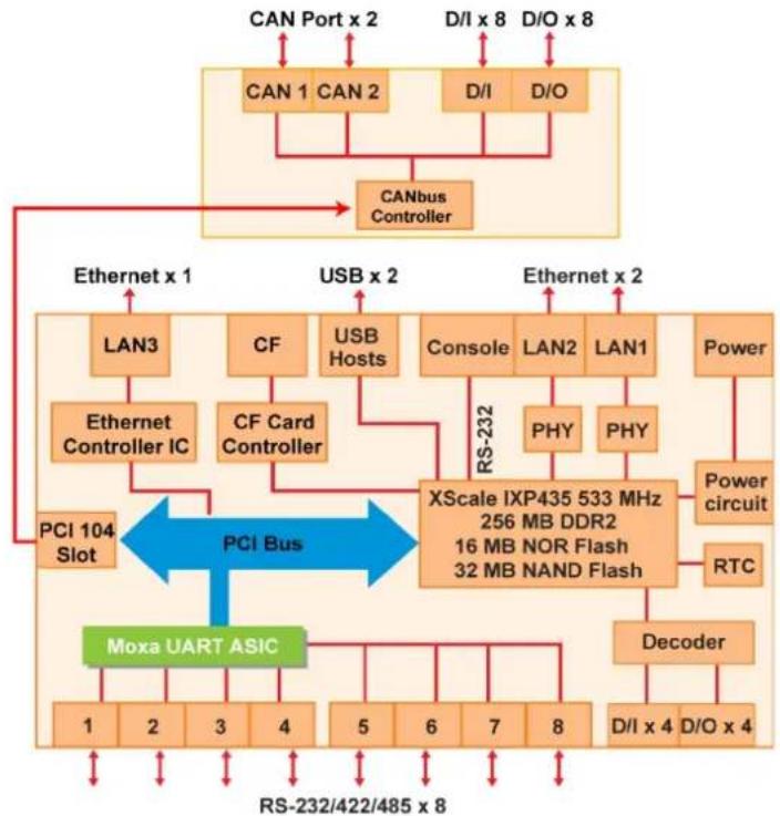
flowchart
graph TD
    A["CAN Port x 2"] --> B["CAN1"]
    C["D/I x 8"] --> D["D/O"]
    B --> E["CAN2"]
    D --> E
    E --> F["CANbus Controller"]
    F --> G["Ethernet x 1"]
    H["USB x 2"] --> I["LAN3"]
    H --> J["CF"]
    H --> K["USB Hosts"]
    H --> L["Console"]
    H --> M["LAN2"]
    H --> N["LAN1"]
    H --> O["Power"]
    I --> P["Ethernet Controller IC"]
    J --> Q["CF Card Controller"]
    L --> R["XScale IXP435 533 MHz 256 MB DDR2 16 MB NOR Flash 32 MB NAND Flash"]
    M --> S["PHY"]
    N --> T["PHY"]
    O --> U["Power circuit"]
    V["PCI 104 Slot"] --> W["PCI Bus"]
    W --> X["Moxa UART ASIC"]
    X --> Y["Decoder"]
    Y --> Z["D/I x 4"]
    Y --> AA["D/O x 4"]
    W --> AB["RS-232/422/485 x 8"]
    style W fill:#FFD700,stroke:#333
UC-8430
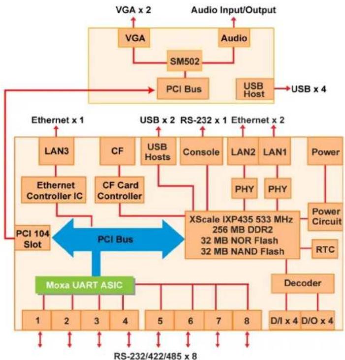
flowchart
```mermaid
graph TD
    subgraph "PCI Bus"
        A["PCI 104 Slot"] --> B["PCI Bus"]
        C["Ethernet x 1"] --> D["LAN3"]
        E["PCI Bus"] --> F["CF"]
        G["PCI Bus"] --> H["CS"]
        I["PCI Bus"] --> J["XScale IXP435 533 MHz 256 MB DDR2 32 MB NOR Flash 32 MB NAND Flash"]
    end
    subgraph "Audio Input/Output"
        K["VGA x 2"] --> L["SM502"]
        M["Audio"] --> N["PCI Bus"]
        O["USB Host"] --> P["USB x 4"]
    end
    subgraph "Moxa UART ASIC"
        Q["1"] --> R["2"]
        S["3"] --> T["4"]
        U["5"] --> V["6"]
        W["7"] --> X["8"]
        Y["D/I x 4"] --> Z["D/O x 4"]
        AA["Decoder"] --> AB["Power Circuit"]
        AC["RTC"] --> AD["Power Circuit"]
    end
    subgraph "USB x 2" (RS-232 x 1) and "Ethernet x 2" (RS-232 x 1) are labeled on the diagram.
LED Indicators
The UC-8410/8416/8418/8430 has 14 LED indicators on the top panel. Refer to the following table for information about each LED.
| LED Name Color Meaning | ||
| Power | Green | Power is on. |
| Off No power input or any other power error. | ||
| Ready | Green | System is ready. |
| Off OS boot up failure or other system initialization error. | ||
| Storage | Yellow (not blinking) | CF card inserted. |
| Yellow (blinking) | Data is being read or written. | |
| Off No CF card inserted. | ||
| Battery | Red (blinking) | Battery is recharging. |
| Off Battery is normal. | ||
| TX 1-8 | Green | Data is being sent through the serial port. |
| Off Data is not being transmitted. | ||
| RX 1-8 | Yellow | Data is being received through the serial port. |
| Off Data is not being received. | ||
Reset Button
The button labeled Reset returns the UC-8410/8416/8418/8430 to its factory default configuration.
Press the Reset button continuously for at least 5 seconds to load the factory default configuration. After the factory default configuration has been loaded, the system will reboot automatically. The Ready LED will blink on and off for the first 5 seconds, and then maintain a steady glow once the system has rebooted.
We recommend that you only use this function if the software is not working properly and you want to load factory default settings. To reset an embedded system, always use the software reboot command / > reboot to protect the integrity of data being transmitted or processed.

ATTENTION
Reset button preserves user's data
The Reset button will NOT format the user directory and erase the user's data. Pressing the Reset button continuously for at least 5 seconds will only load the configuration file. For the Linux OS, all files in the /etc, /home and /tmp directories will revert to their factory defaults, but other user data will still exist in the Flash ROM. For the Windows CE 6.0 OS, all configuration in registries will revert to their factory defaults.
Real Time Clock
The UC-8410/8416/8418/8430's real time clock is powered by a lithium battery. We strongly recommend that you do not replace the lithium battery without help from a qualified Moxa support engineer. If you need to change the battery, contact the Moxa RMA service team.

WARNING
There is a risk of explosion if the battery is replaced by an incorrect type.
The following topics are covered in this chapter:
□ Wall or Cabinet Mounting
□ DIN-Rail Mounting
Wall or Cabinet Mounting
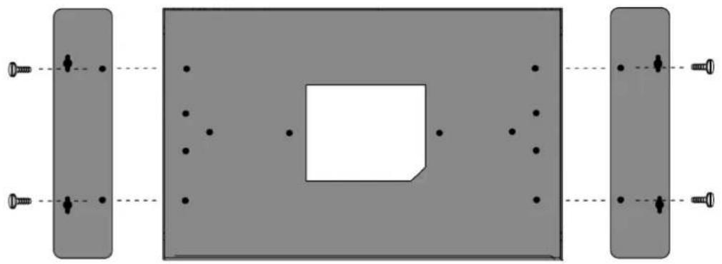
The two metal brackets that come standard with the UC-8410/8416/8418/8430 are used to attach the UC-8410/8416/8418/8430 to a wall or the inside of a cabinet. First, use two screws per bracket to attach the brackets to the bottom of the UC-8410/8416/8418/8430 (Fig. A). Next, use two screws per bracket to attach the UC-8410/8416/8418/8430 to a wall or cabinet (Fig. B).
natural_image
Pure mechanical assembly diagram showing two rectangular components with bolt holes and a central square component, no text or symbols present.Figure A: UC-8410/8416/8418/8430 Embedded Computer—Wall Mounting Brackets (bottom view)
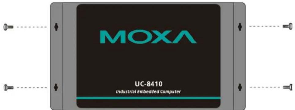
Figure B: UC-8410/8416/8418/8430 Embedded Computer—Wall Mounting Brackets (top view)
DIN-Rail Mounting
An aluminum DIN-Rail attachment plate is included with the product. If you need to reattach the DIN-Rail attachment plate to the UC-8410/8416/8418/8430, make sure the stiff metal spring is situated towards the top, as shown in the following figures.
STEP 1: Insert the top of the DIN-Rail into the slot just below the stiff metal spring.
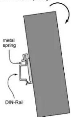
STEP 2: The DIN-Rail attachment unit will snap into place as shown below.
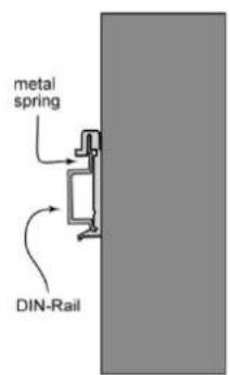
To remove the UC-8410/8416/8418/8430 from the DIN-Rail, simply reverse Steps 1 and 2.
This section describes how to connect the UC-8410/8416/8418/8430 to serial devices for first time testing purposes.
The following topics are covered in this chapter:
□ Wiring Requirements
□ Connecting the Power
☐ Connecting to VGA Monitors (UC-8430 only)
□ Connecting to the Network
□ Connecting to a Serial Device
☐ Connecting to a CAN Device
☐ Connecting to a Speaker or a Headphone (UC-8430 only)
□ Connecting to the Console Port
CompactFlash
USB
□ DI / DO
Digital Input Wiring
▶ Digital Output Wiring
Wiring Requirements

ATTENTION
Safety First!
Be sure to disconnect the power cord before installing and/or wiring your UC-8410/8416/8418/8430.
Wiring Caution!
Calculate the maximum possible current in each power wire and common wire. Observe all electrical codes dictating the maximum current allowable for each wire size.
If the current goes above the maximum ratings, the wiring could overheat, causing serious damage to your equipment.
Temperature Caution!
Be careful when handling the UC-8410/8416/8418/8430. When plugged in, the UC-8410/8416/8418/8430's internal components generate heat, and the outer casing may feel hot to the touch.
You should also observe the following common wiring rules:
- Use separate paths to route wiring for power and devices. If power wiring and device wiring paths must cross, make sure the wires are perpendicular at the intersection point.
NOTE: Do not run signal or communication wiring and power wiring in the same wire conduit. To avoid interference, wires with different signal characteristics should be routed separately. - You can use the type of signal transmitted through a wire to determine which wires should be kept separate. The rule of thumb is that wiring that shares similar electrical characteristics can be bundled together.
- Keep input wiring and output wiring separate.
• Where necessary, we strongly recommend that you label wiring to all devices in the system.
Connecting the Power
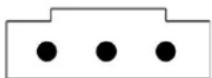
The UC-8410/8416/8418/8430 has a 3-pin terminal block for a 12 to 48 VDC power input.
The following figures show how the power input interface connects to external power source. If the power is properly supplied, t the Ready LED will illuminate with a solid green color after 30 to 60 seconds have passed.
DC 12-48V
V+V-

ATTENTION
The power for this product is intended to be supplied by a Listed Power Supply Unit that is rated to deliver 12 to 48 VDC at a minimum of 1280 mA for 12 VDC, and 300 mA for 48 VDC.
Grounding the UC-8410/8416/8418/8430
Grounding and wire routing help limit the effects of noise due to electromagnetic interference (EMI). Run the ground connection from the ground screw to the grounding surface prior to connecting devices.

ATTENTION
This product is intended to be mounted to a well-grounded mounting surface, such as a metal panel.
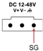
SG: The Shielded Ground (sometimes called Protected Ground) contact is the right most contact of the 3-pin power terminal block connector when viewed from the angle shown here. Connect the SG wire to an appropriate grounded metal surface.

ATTENTION
A shielded-type power cord is required in order to meet FCC emission limits and also to prevent interference to nearby radio and television reception. It is essential that only the supplied power cord be used.
You are cautioned that changes or modifications not expressly approved by the party responsible for compliance could void your authority to operate the equipment.
Connecting to VGA Monitors (UC-8430 only)
The UC-8430 comes with two D-sub 15-pin female connectors on the rear panel to connect two VGA monitors. To ensure that the monitor image remains clear, be sure to tighten the monitor cable after connecting it to the UC-8430. The pin assignments of the VGA connectors are shown below.
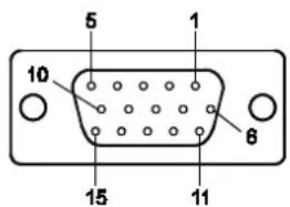
DB15 Female Connector
| Pin No. | Signal Definition |
| 1 Red | |
| 2 Green | |
| 3 Blue | |
| 4 NC | |
| 5 GND | |
| 6 GND | |
| 7 GND | |
| 8 GND | |
| 9 VCC | |
| 10 GND | |
| 11 NC | |
| 12 DDC2B | Data |
| 13 HSYNC | |
| 14 VSYNC | |
| 15 DDC2B | Clock |
Connecting to the Network
Connect one end of the Ethernet cable to one of the UC-8410/8416/8418/8430's 10/100M Ethernet ports (8-pin RJ45) and the other end of the cable to the Ethernet network. If the cable is properly connected, the UC-8410/8416/8418/8430 will indicate a valid connection to the Ethernet in the following ways:

The lower right corner LED indicator maintains a solid green color when the cable is properly connected to a 100 Mbps Ethernet network. The LED will flash on and off when Ethernet packets are being transmitted or received.
The lower left corner LED indicator maintains a solid orange color when the cable is properly connected to a 10 Mbps Ethernet network. The LED will flash on and off when Ethernet packets are being transmitted or received.
| Pin Signal | |
| 1 ETx+ | |
| 2 ETx- | |
| 3 ERx+ | |
| 4 - | |
| 5 - | |
| 6 ERx- | |
| 7 - | |
| 8 - | |
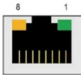
The UC-8416 has 8 10/100 Mbps switch ports. The LED indicators and pin assignments are exactly the same as the Ethernet ports.
Connecting to a Serial Device
Use properly wired serial cables to connect the UC-8410/8416/8418/8430 to serial devices. The UC-8410/8416/8418/8430's serial ports (P1 to P8) use 8-pin RJ45 connectors. The ports can be configured by software for RS-232, RS-422, or 2-wire RS-485. The precise pin assignments are shown in the following table:
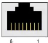
| Pin | RS-232 | RS-422/RS-485-4w | RS-485-2w |
| 1 | DSR | - | - |
| 2 | RTS | TXD+ | - |
| 3 | GND | GND | GND |
| 4 | TXD | TXD- | - |
| 5 | RXD | RXD+ | Data+ |
| 6 | DCD | RXD- | Data- |
| 7 | CTS | - | - |
| 8 | DTR | - | - |
Connecting to a CAN Device
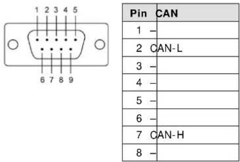
CAN Ports (UC-8418 only)
The UC-8418 has 2 CAN ports for connecting CAN devices. The CAN ports (CAN1 and CAN2) use DB9 male connectors. The pin assignments are shown in the following table:
Connecting to a Speaker or a Headphone (UC-8430 only)
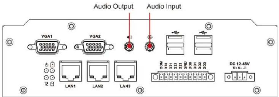
The UC-8430 comes with audio input and output interfaces for connecting a microphone and speaker or headphones. See the following figure for details.
Connecting to the Console Port
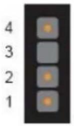
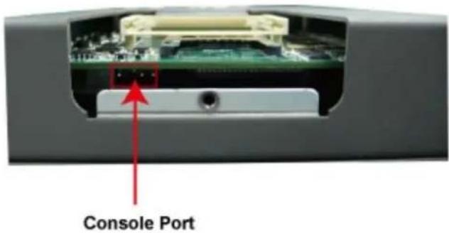
The UC-8410/8416/8418/8430's console port is a 4-pin pin header RS-232 port. Refer to the following figure for console port cable pin assignments.
Serial Console Port and Pinouts
| Pin Signal | |
| 1 | TxD |
| 2 | RxD |
| 3 | NC |
| 4 | GND |
Serial Console Cable
natural_image
Black and white photo of a USB cable with an external connector (no text or symbols visible)The console port is located blow the CF card socket. Use a screwdriver to remove the two screws holding the cover to the embedded computer's housing.
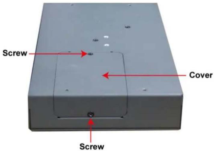
Refer to the following figure for the location of the console port.
CompactFlash
The UC-8410/8416/8418/8430 provides one CompactFlash slot that supports CompactFlash type I/II card expansion. Currently, Moxa provides a CompactFlash card for storage expansion. Be sure of power off the computer before inserting or removing the CompactFlash card.
See the following description for CompactFlash card installation instructions.
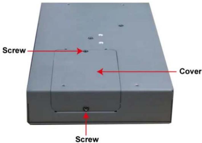
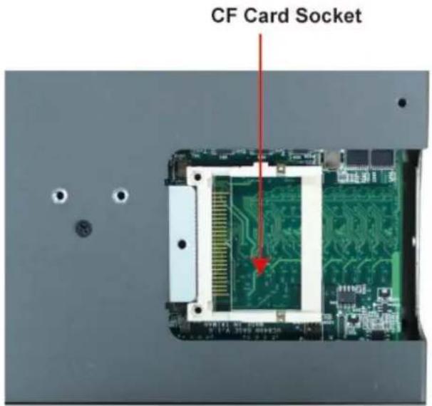
The CF cover is located on the back of the UC-8410/8416/8418/8430. Use a screwdriver to remove the cover and access the slot. See the following figure for the locations of the CF socket.
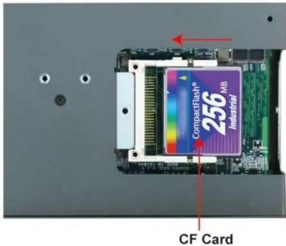
If you need device drivers for other kinds of mass storage cards, contact Moxa for information on how to initiate a cooperative development project.
USB
The UC-8410/8416/8418/8430 provides two or six USB 2.0 hosts. The USB hosts now support adding USB storage devices.
DI / DO
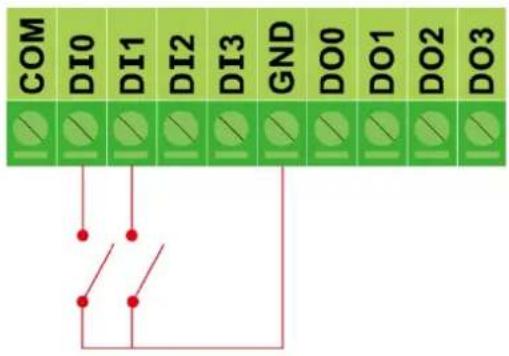
The UC-8410/8416/8430 have 4-ch digital outputs and 4-ch digital inputs, while the UC-8418 has 12-ch digital inputs and 12-ch digital outputs. The pinouts for the I/O are shown in the following figures:
Digital Input Wiring
Dry Contact
Wet Contact
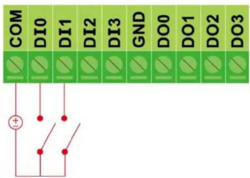
Note: If are using wet contacts, you must connect "COM" to power.
Digital Output Wiring
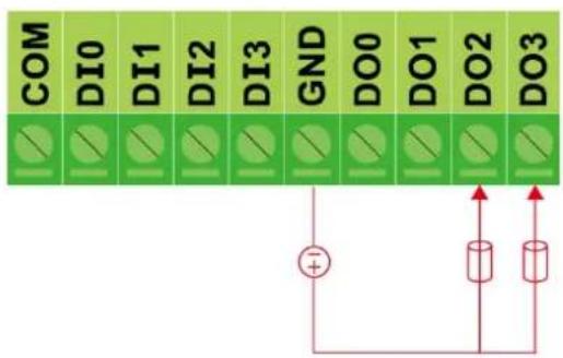

This device complies with part 15 of the FCC Rules. Operation is subject to the following two conditions: (1) This device may not cause harmful interference, and (2) this device must accept any interference received, including interference that may cause undesired operation.
- UC-8410/8416/8418/8430
- Hardware User's Manual
- Copyright Notice
- Trademarks
- Disclaimer
- Technical Support Contact Information
- Moxa Americas
- Moxa Europe
- Moxa India
- Moxa China (Shanghai office)
- Moxa Asia-Pacific
- Appearance and Dimensions 2-1
- Mounting Options.... 3-1
- Hardware Connection Description 4-1
- Regulatory Approval Statements...... A-1
- Overview
- Package Checklist
- Product Features
- Product Hardware Specifications
- Computer
- Flash:
- Expansion Bus: PCI/104 onboard
- Storage
- Other Peripherals (UC-8430 only)
- Display (UC-8430 only)
- Ethernet Interface
- Serial Interface
- Serial Communication Parameters
- Serial Signals
- Digital Input
- Digital Input Levels for Dry Contacts:
- Digital Input Levels for Wet Contacts:
- Digital Output
- LEDs
- Physical Characteristics
- Environmental Limits
- Power Requirements
- Regulatory Approvals
- Reliability
- Warranty
- Appearance
- LED Indicators
- Reset Button
- ATTENTION
- Reset button preserves user's data
- Real Time Clock
- WARNING
- Wall or Cabinet Mounting
- DIN-Rail Mounting
- Wiring Requirements
- Safety First!
- Wiring Caution!
- Temperature Caution!
- Connecting the Power
- Connecting to VGA Monitors (UC-8430 only)
- Connecting to the Network
- Connecting to a Serial Device
- Connecting to a CAN Device
- Connecting to a Speaker or a Headphone (UC-8430 only)
- Connecting to the Console Port
- CompactFlash
- USB
- DI / DO
- Digital Input Wiring
Brand : Moxa
Model : UC-8430-LX
Category : Server