
BT7582 - Shelf Support B-Tech - Free user manual and instructions
Find the device manual for free BT7582 B-Tech in PDF.

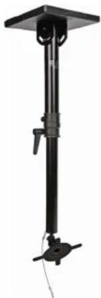
| Product Type | Ceiling Mount for Flat Screen Displays |
| Brand | B-Tech |
| Model | BT7582 |
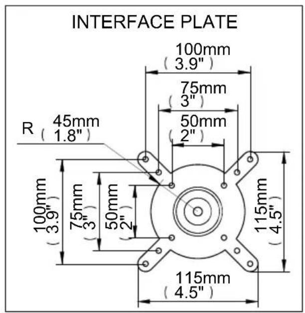
| VESA Compatibility | 50x50mm, 75x75mm, 100x100mm |
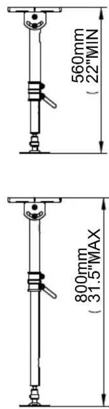
| Adjustable Ceiling Drop | 560mm - 800mm (22" - 31.5") |
| Upper Tube Diameter | 42mm (1.7") |
| Lower Tube Diameter | 35mm (1.4") |
| Tilt (Pole for Angled Ceilings) | +/-50° |
| Swivel | 360° |
| Tilt (Screen) | +/-90° |
| Max Weight Capacity | 25 kg (55 lbs) |
| Material | Steel |
| Color | Black |
| Safety Features | Safety wire, hand lever for easy drop adjustment |
| Cable Management | Integrated cable routing with cover plates |
| Included Accessories | Ceiling bracket, extension poles, ball joint, VESA plate, cover plates, hardware, security cable, hex keys |
| Installation Tools Required | 15mm spanner/socket, crosshead screwdriver, drill, 12mm masonry bit or 9mm wood bit, pencil, stud finder (optional) |
| Maintenance | Periodic inspection of all fixings and tightness |
| Repairability | Contact B-Tech for spare parts or service |
| General Information | Intended for indoor use only; professional installation recommended |
Frequently Asked Questions - BT7582 B-Tech
User questions about BT7582 B-Tech
0 question about this device. Answer the ones you know or ask your own.
Ask a new question about this device
Download the instructions for your Shelf Support in PDF format for free! Find your manual BT7582 - B-Tech and take your electronic device back in hand. On this page are published all the documents necessary for the use of your device. BT7582 by B-Tech.
USER MANUAL BT7582 B-Tech
WITH TILT AND SWIVEL
INSTALLATION GUIDE & PARTS LIST
This Pack Contains 1 Mount
PLEASE KEEP THIS FOR FUTURE REFERENCE
FEATURES
- Fits 50 x 50mm, 75 x 75mm and 100 x 100mm VESA mounting patterns
- Adjustable ceiling drop: 560mm (22") - 800mm (31.5")
• Upper tube diameter: 42mm (1.7") - Lower tube diameter: 35mm (1.4")
• +/-50° Tilt of pole for angled ceilings - 360° Swivel at mount +/-90° Tilt facility
- Hand lever allows easy adjustment of ceiling drop
• Safety wire for extra security - Cable management
• Coverplates included for smart installation
CONTENTS
Installation Safety Notes....2
Parts List....4
Installation Instructions....6
Product Dimensions....11
B-Tech Contact Details....12
INSTALLATION TOOLS REQUIRED
15mm (9/16") spanner or socket
Crosshead screwdriver
Drill

12mm (1/2") masonry bit or 9mm (3/8") wood bit
Pencil

Stud finder (optional)

B-TECH AUDIO VIDEO MOUNTS
www.btechavmounts.com
INSTALLATION SAFETY INSTRUCTIONS
CAUTION: This ceiling mount is intended for use only with the maximum weights indicated. Use with flat screens heavier than the maximum may result in instability causing possible injury.
Do not attempt to install this product until all instructions and warnings have been read and properly understood. Please keep these instructions for future reference.
B-Tech International Limited, its distributors and dealers are not liable or responsible for damage or injury caused by improper installation, improper use or failure to observe these safety instructions. In such cases, all guarantees will expire.
General
B-Tech International Ltd recommends that a professional AV installer or other suitably qualified person install this product. Great care must always be taken during installation as most AV equipment is of a fragile nature, possibly heavy and easily damaged if dropped.
If you do not fully understand the instructions or are not sure how to install this product safely, then please consult a professional for advice and/or to install this product for you. Failure to mount this product correctly may cause serious injury or death both during installation and at any time thereafter. Do not mount any AV equipment that exceeds the specific weight limit of the product you are installing. This weight limit will be clearly stated on each product and its packaging and will vary from product to product.
Product location
Please pay careful attention to where this product is located. Some ceilings are not suitable for installation.
If located in a public or frequently populated area ensure that the product is out of the immediate reach of people. If any AV equipment is to be suspended over the likely path or location of people then great care should be taken to secure all parts of the installation from falling. When drilling holes in ceilings it is essential to avoid contact with electrical cables and water or gas pipes contained within. Use of a good quality live wire detector and hidden object locator is therefore recommended. Only drill into structures when you are sure it is safe to do so.
Fixing hardware
It is highly recommended that all wall fixing screws be used where supplied and that the purpose of all other fixing hardware is fully understood. In some cases more AV equipment fixing hardware will be supplied to accommodate different models of equipment and set up configurations.
The installer must be satisfied that any supplied fixing hardware is suitable for each specific installation. If any fixing screws or included hardware are deemed not sufficient for a safe installation then please consult a professional or your local hardware store.
Hazard limitation
When routing cables take advantage of any built in cable management features that the product might provide and ensure that all cables are tidy and secure. Check to see that any moving aspect of the product can do so unhindered by any cabling.
Some products have moving parts and the potential to cause injury through the crushing or trapping of fingers or other body parts.
Particular attention to the nature of moving parts is required especially when assembling installing and adjusting during set up.
Immediately after installations double-check that the work done is safe and secure. Double-check all necessary fixings are present and are of ample tightness.
It is recommended that periodic inspections of the product and its fixing points are made as frequently as possible to ensure that safety is maintained. If in doubt consult a professional AV installer or other suitably qualified person.
CS
WALL FIXING KIT
(FOR FIXING MOUNT TO WALL)
| REF | PART NAME QTY | |
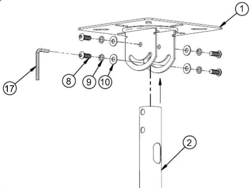
| 1 | CEILING BRACKET 1 | |
| 2 | UPPER EXTENSION POLE 1 | |
| 3 | LOWER EXTENSION POLE 1 | |
| 4 | BALL JOINT 1 | |
| 5 | ADAPTOR - M8 FEMALE THREAD 1 | |
| 6 | VESA INTERFACE PLATE 1 | |
| 7 | COVER PLATE 2 | |
| 8 | M8 X 20mm HEX SCREW 5 | |
| 9 | M8 SPRING WASHER 5 | |
| 10 | M8 METAL WASHER | |
| 11 | ADJUSTMENT LEVER | 1 |
| 12 | M6 X 6mm GRUB SCREW | 2 |
| 13 | M6 X 10mm GRUB SCREW | 2 |
| 14 | SECURITY CABLE | 1 |
| 15 | 2.5mm HEX KEY (FOR PARTS A & B) | 1 |
| 16 | 3mm HEX KEY (FOR PARTS 12 & 13) | 1 |
| 17 | 5mm HEX KEY (FOR PART 8) | 1 |
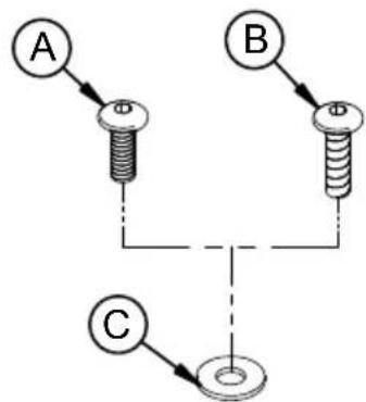
| INTERFACE KIT | ||
| A | M4 X 12mm HEX SCREW 4 | |
| B | M4 X 15mm HEX SCREW 1 | |
| C | M5 METAL WASHER (FOR PARTS A & B) | 1 |
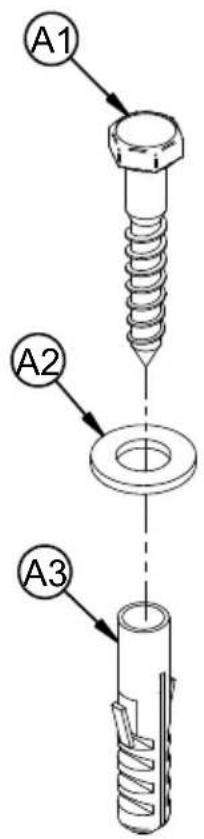
| FIXING KIT | ||
| A1 | M10 X 60mm COACH SCREW | 4 |
| A2 | M10 METAL WASHER (FOR PART A1) | 4 |
| A3 | No. 12 WALL PLUG (FOR PART A1) | 4 |
FLAT SCREEN INTERFACE KIT
(FOR ATTACHING MOUNT TO BACK OF FLAT SCREEN)

INSTALLATION INSTRUCTIONS
1
Attach upper extension pole to ceiling plate.
z
Fix ceiling plate to the ceiling.

6
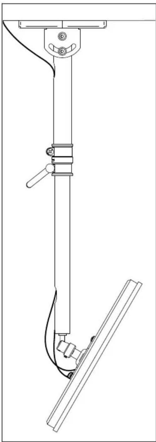
ANGLED CEILING

3
Slide on the covers.

4
Fix the adaptor to the interface plate.

5
Attach interface plate to the flat screen using 3 interface screws (part A).

6
Connect the adaptor to the ball joint and secure using parts 13.

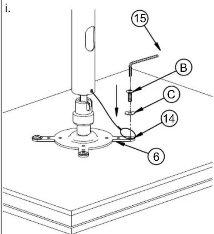
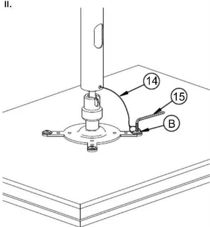
7
Place cable loop over vacant screw hole, secure in place using parts B and C.
ii.
8
Cable management.

9
Adjusting the flat screen.
i. To adjust drop, loosen hand lever, adjust drop, then re-tighten.

ii. To tilt/roll and swivel, loosen parts 12, adjust and re-tighten.

10
BT7582 PRODUCT DIMENSIONS
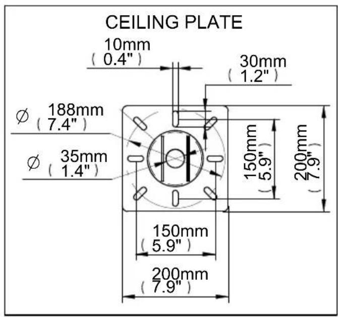


THESE INSTRUCTIONS ARE INTENDED AS A GUIDE ONLY AND B-TECH ACCEPTS NO LIABILITY FOR THE ACCURACY OF THE INFORMATION CONTAINED IN THIS DOCUMENT.

BETTER BY DESIGN
www.btechavmounts.com
B-TECH AUDIO VIDEO MOUNTS
HEAD OFFICE
Bennett House, Long March, Daventry, Northants., NN11 4NR, UK
Email: info@btechavmounts.co.uk
EUROPE
BELGIUM
Brixtonlaan 32, Zaventem 1930,
Brussels, Belgium
Email: info@btechproav.com
GERMANY
Ruby Industrial Complex,
Singapore 347740
Email: info@btechavmounts.com.sg
ASIA PACIFIC
1503 Prosperity Millennia Plaza,
Quarry Bay, Hong Kong
Email: info@btechavmounts.com.hk
©2010 Bennett Technologies Limited. All rights reserved.
B-Tech Audio Video Mounts is a division of Bennett Technologies Limited.
B-Tech, Better By Design and Mountlogic are registered trademarks of Bennett Technologies Limited.
All other brands and product names are trademarks of their respective owners.
Photographs are for illustrative purposes only. E&OE.
IP-BT7582-V2-OR2BX-280910-01 MADE IN CHINA
- FEATURES
- CONTENTS
- INSTALLATION TOOLS REQUIRED
- INSTALLATION SAFETY INSTRUCTIONS
- CAUTION: THIS CEILING MOUNT IS INTENDED FOR USE ONLY WITH THE MAXIMUM WEIGHTS INDICATED. USE WITH FLAT SCREENS HEAVIER THAN THE MAXIMUM MAY RESULT IN INSTABILITY CAUSING POSSIBLE INJURY
- GENERAL
- PRODUCT LOCATION
- FIXING HARDWARE
- HAZARD LIMITATION
- CS
- INSTALLATION INSTRUCTIONS
- BT7582 PRODUCT DIMENSIONS
- B-TECH AUDIO VIDEO MOUNTS
Brand : B-Tech
Model : BT7582
Category : Shelf Support