
Intel Xeon E5630 - Processor HP - Free user manual and instructions
Find the device manual for free Intel Xeon E5630 HP in PDF.


| Product Type | Processor |
| Brand | HP (Intel Xeon) |
| Model | Intel Xeon E5630 |
| Socket | FCLGA1366 |
| Number of Cores | 6 |
| Number of Threads | 12 (with Hyper-Threading) |
| Base Clock Speed | 2.53 GHz |
| Max Turbo Boost | 2.80 GHz |
| Cache (L3) | 12 MB |
| QuickPath Interconnect Speed | 5.86 GT/s |
| Memory Support | DDR3-1066 |
| Thermal Design Power (TDP) | 80 W |
| Stepping | B-1 |
| Dimensions (approximate) | 45 mm x 45 mm |
| Weight (approximate) | 20 g |
| Maintenance | Ensure proper thermal paste application and clean contact pins |
| Safety Precautions | Handle with ESD protection; install only in compatible socket |
| Spare Parts Availability | Not applicable (processor not field-repairable) |
| General Information | Part of Intel Xeon 5600 series; designed for servers and workstations |
Frequently Asked Questions - Intel Xeon E5630 HP
User questions about Intel Xeon E5630 HP
0 question about this device. Answer the ones you know or ask your own.
Ask a new question about this device
Download the instructions for your Processor in PDF format for free! Find your manual Intel Xeon E5630 - HP and take your electronic device back in hand. On this page are published all the documents necessary for the use of your device. Intel Xeon E5630 by HP.
USER MANUAL Intel Xeon E5630 HP
Intel® Xeon® Processor 5600 Series
Specification Update
March 2010
INFORMATION IN THIS DOCUMENT IS PROVIDED IN CONNECTION WITH INTEL® PRODUCTS. NO LICENSE, EXPRESS OR IMPLIED, BY ESTOPPEL OR OTHERWISE, TO ANY INTELLECTUAL PROPERTY RIGHTS IS GRANTED BY THIS DOCUMENT. EXCEPT AS PROVIDED IN INTEL'S TERMS AND CONDITIONS OF SALE FOR SUCH PRODUCTS, INTEL ASSUMES NO LIABILITY WHATSOEVER, AND INTEL DISCLAIMS ANY EXPRESS OR IMPLIED WARRANTY, RELATING TO SALE AND/OR USE OF INTEL PRODUCTS INCLUDING LIABILITY OR WARRANTIES RELATING TO FITNESS FOR A PARTICULAR PURPOSE, MERCHANTABILITY, OR INFRINGEMENT OF ANY PATENT, COPYRIGHT OR OTHER INTELLECTUAL PROPERTY RIGHT.
UNLESS OTHERWISE AGREED IN WRITING BY INTEL, THE INTEL PRODUCTS ARE NOT DESIGNED NOR INTENDED FOR ANY APPLICATION IN WHICH THE FAILURE OF THE INTEL PRODUCT COULD CREATE A SITUATION WHERE PERSONAL INJURY OR DEATH MAY OCCUR.
Intel may make changes to specifications and product descriptions at any time, without notice. Designers must not rely on the absence or characteristics of any features or instructions marked "reserved" or "undefined." Intel reserves these for future definition and shall have no responsibility whatsoever for conflicts or incompatibilities arising from future changes to them. The information here is subject to change without notice. Do not finalize a design with this information.
The products described in this document may contain design defects or errors known as errata which may cause the product to deviate from published specifications. Current characterized errata are available on request.
Contact your local Intel sales office or your distributor to obtain the latest specifications and before placing your product order.
All products, platforms, dates, and figures specified are preliminary based on current expectations, and are subject to change without notice. All dates specified are target dates, are provided for planning purposes only and are subject to change.
This document contains information on products in the design phase of development. Do not finalize a design with this information. Revised information will be published when the product is available. Verify with your local sales office that you have the latest datasheet before finalizing a design.
Intel processor numbers are not a measure of performance. Processor numbers differentiate features within each processor family, not across different processor families. See http://www.intel.com/products/processor_number for details
See the http://processorfinder.intel.com/ or contact your Intel representative for more information.
Hyper-Threading Technology requires a computer system with a processor supporting HT Technology and an HT Technology-enabled chipset, BIOS and operating system. Performance will vary depending on the specific hardware and software you use. For more information including details on which processors support HT Technology, see http://www.intel.com/technology/platform-technology/hyper-threading/index.htm.
Intel® Turbo Boost Technology requires a PC with a processor with Intel Turbo Boost Technology capability. Intel Turbo Boost Technology performance varies depending on hardware, software and overall system configuration. Check with your PC manufacturer on whether your system delivers Intel Turbo Boost Technology. For more information, see http://www.intel.com/technology/turboboost.
Intel, Xeon, Pentium, Celeron, Intel Enhanced SpeedStep Technology, Intel Core, the Intel logo are trademarks or registered trademarks of Intel Corporation or its subsidiaries in the United States and other countries.
* Other names and brands may be claimed as the property of others.
Copyright © 2010, Intel Corporation. All Rights Reserved.
Contents
Revision History....5
Preface 6
Identification Information 8
Summary Table of Changes....11
Errata Summary....14
Specification Changes....44
Specification Clarifications 45
Documentation Changes....46
Revision History
| Doc ID Revision Description Date | |||
| 323372 -001 | Initial Release March 2010 | ||
Preface
This document is an update to the specifications contained in the Affected Documents able below. This document is a compilation of device and documentation errata, specification clarifications and changes. It is intended for hardware system manufacturers and software developers of applications, operating systems, or tools.
Information types defined in Nomenclature are consolidated into the specificationupdate and are no longer published in other documents.
This document may also contain information that was not previously published.
Affected Documents
| Document Title Notes | 1 |
| Intel® Xeon® Processor 5600 Series Datasheet Volume 1 & 2 | 323369 & 323370 |
Related Documents
| Document Title Location Notes | ||
| Intel® 64 and IA-32 Architectures Software Developer's ManualVolume 1: Basic ArchitectureVolume 2A: Instruction Set Reference, A-MVolume 2B: Instruction Set Reference, N-ZVolume 3A: System Programming Guide, Part 1Volume 3B: System Programming Guide, Part 2 | 253665253666253667253668253669 | 2 |
| Intel® 64 and IA-32 Architectures Optimization Reference Manual | 248966 2 | |
| Intel® Virtualization Technology Specification for Directed I/O Architecture Specification | D51397-001 2 |
Notes:
- Document is available publicly at http://developer.intel.com.
Nomenclature
S-Spec Number is a five-digit code used to identify products. Products are differentiated by their unique characteristics, e.g., core speed, L2 cache size, package type, etc. as described in the processor identification information table. Read all notes associated with each S-Spec number.
Errata are design defects or errors. These may cause the processor behavior to deviate from published specifications. Hardware and software designed to be used with any given stepping must assume that all errata documented for that stepping are present on all devices.
Specification Changes are modifications to the current published specifications. These changes will be incorporated in the next release of the specification.
Specification Clarifications describe a specification in greater detail or further highlight a specification's impact to a complex design situation. These clarifications will be incorporated in any new release of the specification.
Documentation Changes include typographical errors, omissions, or incorrect information from the current published specifications. These will be incorporated in the next release of the specification.
Note:
Errata remain in the specification update throughout the product's life cycle, or until a particular stepping is no longer commercially available. Under these circumstances, errata removed from the specification update are archived and available upon request.
Specification changes, specification clarifications, and documentation changes are removed from the sightings report and/or specification update when the appropriate changes are made to the appropriate product specification or user documentation.
Identification Information
Component Identification
The Intel® Xeon® Processor 5600 Series stepping can be identified by the following register contents.
Table 1. Intel® Xeon® Processor 5600 Series Signature/ Version
| Reserved | Extended Family ^1 | Extended Model ^2 | Reserved | Processor Type ^3 | Family Code ^4 | Model Number ^5 | Stepping ID ^6 |
| 31:28 27 | :20 19:16 15 | :14 13:12 1 | 1:8 7:4 3:0 | ||||
| 00000000b | 0010b 00b 01 | 10 110 | 0b XXXXb |
Notes:
-
The Extended Family, bits [27:20] are used in conjunction with the Family Code, specific in bits [11:8], to indicate whether the processor belongs to the Intel386, Intel486, Pentium, Pentium Pro, Pentium 4, or Intel® Core™ processor family.
-
The Extended Model, bits [19:16] in conjunction with the Model Number, specified in bits [7:4], are used to identify the model of the processor within the processor family.
-
The Processor Type, specified in bits [13:12] indicates whether the processor is an original OEM processor, an OverDrive processor, or a dual processor (capable of being used in a dual processor system).
-
The Family Code corresponds to bits [11:8] of the EDX register after RESET, bits [11:8] of the EAX register after the CPUID instruction is executed with a 1 in the EAX register, and the generation field of the Device ID register accessible through Boundary Scan.
-
The Model Number corresponds to bits [7:4] of the EDX register after RESET, bits [7:4] of the EAX register after the CPUID instruction is executed with a 1 in the EAX register, and the model field of the Device ID register accessible through Boundary Scan.
-
The Stepping ID in bits [3:0] indicates the revision number of that model. See Table 2 for the processor stepping ID number in the CPUID information.
When EAX is initialized to a value of '1', the CPUID instruction returns the Extended Family, Extended Model, Processor Type, Family Code, Model Number, and Stepping ID in the EAX register. Note that the EDX processor signature value after reset is equivalent to the processor signature output value in the EAX register.
Cache and TLB descriptor parameters are provided in the EAX, EBX, ECX and EDX registers after the CPUID instruction is executed with a 2 in the EAX register.
Component Marking
The Intel® Xeon® Processor 5600 Series can be identified by the following component markings:
Figure 1. Processor Top-side Markings (Example)
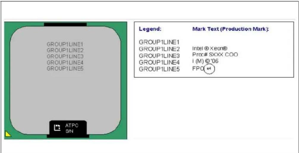
Table 2. Intel® Xeon® Processor 5600 Series Identification (Sheet 1 of 2)
| S-Spec Number | Stepping | CPUID ^1 | Core Frequency (GHz) ^17 /Intel QuickPath Interconnect (GT/s) / DDR3 (MHz) / DDR3L (MHz) | Available bins of Intel Turbo Boost Technology | Cache Size (MB) | TDP (W) | Notes |
| SLBV5 B-1 | 0x000206 | C2 3.33 / 6.40 / | 1333 / 1333 1/1/1/1/2/2 12 130 | 2 | |||
| SLBV9 B-1 | 0x000206 | C2 2.93 / 6.40 / | 1333 / 1333 2/2/2/2/3/3 12 130 | 3 | |||
| SLBV7 B-1 | 0x000206 | C2 2.80 / 6.40 / | 1333 / 1333 2/2/2/2/3/3 12 95 | 4 | |||
| SLBVA B-1 | 0x000206 | C2 3.06 / 6.40 / | 1333 / 1333 | na/na/2/2/3/3 | 12 95 | 7 | |
| SLBV6 B-1 | 0x000206 | C2 2.80 / 6.40 / | 1333 / 1333 2/2/2/2/3/3 12 95 | 5 | |||
| SLBV3 B-1 | 0x000206 | C2 2.66 / 6.40 / | 1333 / 1333 2/2/2/2/3/3 12 95 | 6 | |||
| SLBVC B-1 | 0x000206 | C2 2.66 / 5.86 / | 1066 / 1066 | na/na/1/1/2/2 | 12 80 | 8 | |
| SLBVB B-1 | 0x000206 | C2 2.53 / 5.86 / | 1066 / 1066 2/2/2/2/3/3 12 80 | 9 | |||
| SLBV4 B-1 | 0x000206 | C2 2.40 / 5.86 / | 1066 /1066 | na/na/1/1/2/2 | 12 80 | 10 | |
| SLBV8 B-1 | 0x000206 | C2 2.26 / 5.86 / | 1333 / 1333 2/2/3/3/4/4 12 60 | 11 | |||
| SLBVD B-1 | 0x000206 | C2 2.13 / 5.86 / | 1066 / 1066 | na/na/1/1/2/2 | 12 40 | 12 | |
| SLBVJ B-1 | 0x000206 | C2 1.86 / 4.80 / | 1066 / 1066 na 12 40 | 13 |
Table 2. Intel® Xeon® Processor 5600 Series Identification (Sheet 2 of 2)
| S-Spec Number | Stepping | CPUID ^1 | Core Frequency (GHz) ^17 /Intel QuickPath Interconnect (GT/s) / DDR3 (MHz) / DDR3L (MHz) | Available bins of Intel Turbo Boost Technology | Cache Size (MB) | TDP (W) | Notes |
| SLBWZ | B-1 0x000 | 206C2 2.40 / 5 | .86 / 1333 / 1333 1/1/2/2/3 | 3/3 12 80 | 14 | ||
| SLBWY | B-1 0x000 | 206C2 2.00 / 5 | .86 / 1333 / 1333 1/1/2/2/3 | 3/3 12 60 | 15 | ||
| SLBX3 | B-1 0x000 | 206C2 1.86 / 5 | .86 / 1066 / 1066 | na/na/1/1/2/3 | 12 40 | 16 |
Notes:
-
CPUID is 0000206Csh, where 's' is the stepping number.
-
This is an Intel® Xeon Processor X5680
-
This is an Intel® Xeon Processor X5677.
-
This is an Intel® Xeon Processor X5670
-
This is an Intel® Xeon Processor X5660
-
This is an Intel® Xeon Processor X5650
-
This is an Intel® Xeon Processor X5667
-
This is an Intel® Xeon Processor E5640.
-
This is an Intel® Xeon Processor E5630
-
This is an Intel® Xeon Processor E5620
-
This is an Intel® Xeon Processor L5640.
-
This is an Intel® Xeon Processor L5630.
-
This is an Intel® Xeon Processor L5609.
-
This is an Intel® Xeon Processor E5645.
-
This is an Intel® Xeon Processor L5638.
-
This is an Intel® Xeon Processor L5618.
-
The core frequency reported in the processor brand string is rounded to 2 decimal digits. (For example, core frequency of 2.6666, repeating 6, is reported as @2.67 in brand string. Core frequency of 2.1333, is reported as @2.13 in brand string.)
Summary Table of Changes
The table included in this section indicate the errata, Specification Changes, Specification Clarifications, or Document Changes which apply to the Intel® Xeon® Processor 5600 Series. Intel may fix some of the errata in a future stepping of the component, and account for the other outstanding issues through documentation or specification changes as noted.
Definitions are listed below for terminology used in the Summary Tables below.
Affected Stepping Column:
X: Errata exists in the stepping indicated. Specification Change or Specification Clarification that applies to this stepping.
Blank: This erratum is fixed, or does not exist, in the listed stepping. Specification Change does not apply to listed stepping.
Status Column:
No Fix: There are no plans to fix this erratum.
Plan Fix: This erratum may be fixed in a future stepping of the product.
Fixed: This erratum has been fixed.
A change bar to the left of the table row indicates this erratum is either new or has been modified from the previous revision of this document.
A = Intel® Xeon® processor 7000 sequence
C = Intel® Celeron® processor
D = Intel® Xeon® processor 2.80 GHz
E = Intel® Pentium® III processor
F = Intel® Pentium® processor Extreme Edition and Intel® Pentium® D processor
I = Intel® Xeon® processor 5000 series
J = 64-bit Intel® Xeon® processor MP with 1MB L2 cache
K = Mobile Intel® Pentium® III processor
L = Intel® Celeron® D processor
M = Mobile Intel® Celeron® processor
N = Intel® Pentium® 4 processor
O = Intel® Xeon® processor MP
P = Intel® Xeon® processor
Q = Mobile Intel® Pentium® 4 processor supporting Intel® Hyper-Threading Technology on 90-nm process technology
R = Intel® Pentium® 4 processor on 90 nm process
S = 64-bit Intel® Xeon® processor with 800 MHz system bus (1 MB and 2 MB L2 cache versions)
T = Mobile Intel® Pentium® 4 processor-M
U = 64-bit Intel® Xeon® processor MP with up to 8MB L3 cache
V = Mobile Intel® Celeron® processor on .13 micron process in Micro-FCPGA package
W= Intel® Celeron® M processor
X = Intel® Pentium® M processor on 90nm process with 2-MB L2 cache and Intel® processor A100 and A110 with 512-KB L2 cache
Y = Intel® Pentium® M processor
Z = Mobile Intel® Pentium® 4 processor with 533 MHz system bus
AA = Intel® Pentium® D processor 900 sequence and Intel® Pentium® processor Extreme Edition 955, 965
AB = Intel® Pentium® 4 processor 6x1 sequence
AC = Intel® Celeron® processor in 478 pin package
AD = Intel® Celeron® D processor on 65 nm process
AE = Intel® Core™ Duo processor and Intel® Core™ Solo processor on 65 nm process
AF = Intel® Xeon® processor LV
AG = Intel® Xeon® processor 5100 series
AH = Intel® Core™2 Duo/Solo Processor for Intel® Centrino® Duo Processor Technology
AI = Intel® Core™2 Extreme processor X6800 and Intel® Core™2 Duo desktop processor E6000 and E4000 sequence
AJ = Intel® Xeon® processor 5300 series
AK = Intel® Core™2 Extreme quad-core processor QX6000 sequence and Intel® Core™2 Quad processor Q6000 sequence
AL = Intel® Xeon® processor 7100 series
AM = Intel® Celeron® processor 400 sequence
AN = Intel® Pentium® dual-core processor
AO = Intel® Xeon® processor 3200 series
AP = Intel® Xeon® processor 3000 series
AQ = Intel® Pentium® dual-core desktop processor E2000 sequence
AR = Intel® Celeron® processor 500 series
AS = Intel® Xeon® processor 7200, 7300 series
AT = Intel® Celeron® processor 200 series
AU = Intel® Celeron® Dual Core processor T1400
AV = Intel® Core™2 Extreme processor QX9650 and Intel® Core™2 Quad processor Q9000 series
AW = Intel® Core™ 2 Duo processor E8000 series
AX = Intel® Xeon® processor 5400 series
AY = Intel® Xeon® processor 5200 series
AZ= Intel® Core™2 Duo processor and Intel® Core™2 Extreme processor on 45-nm process
AAA= Intel® Xeon® processor 3300 series
AAB= Intel® Xeon® E3110 processor
AAC= Intel® Celeron® dual-core processor E1000 series
AAD = Intel ^ Core ^TM2 Extreme processor QX9775
AAE = Intel® Atom™ processor Z5xx series
AAF = Intel® Atom™ processor 200 series
AAG = Intel® Atom™ processor N series
AAH = Intel® Atom™ processor 300 series
AAI = Intel® Xeon® processor 7400 series
AAJ = Intel® Core™ i7 processor and Intel® Core™ i7 Extreme Edition processor
AAK= Intel® Xeon® processor 5500 series
AAL = Intel® Pentium Dual-Core processor E5000 series
BD= Intel® Xeon® processor 5600 series
Table 3. Errata Summary Table (Sheet 1 of 4)
| Errata Number | Steppings | Status ERRATA |
| B-1 | ||
| BD1 X No Fix The Processor may Report a # TS Instead of a # GP Fault | ||
| BD2 X No Fix | REP MOVS/STOS Executing with Fast Strings Enabled and Crossing Page Boundaries with Inconsistent Memory Types may use an Incorrect Data Size or Lead to Memory-Ordering Violations | |
| BD3 X No Fix | Code Segment Limit/Canonical Faults on RSM May be Serviced before Higher Priority Interrupts/Exceptions and May Push the Wrong Address Onto the Stack | |
| BD4 X No Fix Performance Monitor SSE Retired Instructions May Return Incorrect Values | ||
| BD5 X No Fix | No Fix | Premature Execution of a Load Operation Prior to Exception Handler Invocation |
| BD6 X No Fix MOV To/From Debug Registers Causes Debug Exception | ||
| BD7 X No Fix | Incorrect Address Computed For Last Byte of FXSAVE/FXRSTOR Image Leads to Partial Memory Update | |
| BD8 X No Fix Values for LBR/BTS/BTM will be Incorrect after an Exit from SMM | ||
| BD9 X No Fix | No Fix | Single Step Interrupts with Floating Point Exception Pending May Be Mishandled |
| BD10 X No Fix Fault on ENTER Instruction May Result in Unexpected Values on Stack Frame | ||
| BD11 X No Fix | IRET under Certain Conditions May Cause an Unexpected Alignment Check Exception | |
| BD12 X No Fix | General Protection Fault (#GP) for Instructions Greater than 15 Bytes May be Preempted | |
| BD13 X No Fix | General Protection (#GP) Fault May Not Be Signaled on Data Segment Limit Violation above 4-G Limit | |
| BD14 X No Fix | LBR, BTS, BTM May Report a Wrong Address when an Exception/Interrupt Occurs in 64-bit Mode | |
| BD15 X No Fix | MCi_Status Overflow Bit May Be Incorrectly Set on a Single Instance of a DTLB Error | |
| BD16 X No Fix | No Fix | Debug Exception Flags DR6.B0-B3 Flags May be Incorrect for Disabled Breakpoints |
| BD17 X No Fix | No Fix | MONITOR or CLFLUSH on the Local XAPIC's Address Space Results in Hang |
| BD18 X No Fix | Corruption of CS Segment Register During RSM While Transitioning From Real Mode to Protected Mode | |
| BD19 X No Fix | No Fix | A VM Exit on MWAIT May Incorrectly Report the Monitoring Hardware as Armed |
| BD20 X No Fix Performance Monitor Event SEGMENT_REG LOADS Counts Inaccurately | ||
| BD21 X No Fix | #GP on Segment Selector Descriptor that Straddles Canonical Boundary May Not Provide Correct Exception Error Code | |
| BD22 X No Fix | Improper Parity Error Signaled in the IQ Following Reset When a Code Breakpoint is Set on a #GP Instruction | |
| BD23 X No Fix | An Enabled Debug Breakpoint or Single Step Trap May Be Taken after MOV SS/POP SS Instruction if it is Followed by an Instruction That Signals a Floating Point Exception | |
| BD24 X No Fix IA32_MPERF Counter Stops Counting During On-Demand TM1 | ||
Table 3. Errata Summary Table (Sheet 2 of 4)
| Errata Number | Steppings | Status ERRATA | |
| B-1 | |||
| BD25 X | No Fix | Intel® QuickPath Memory Controller May Hang Due to Uncorrectable ECC Errors Occurring on Both Channels in Mirror Channel Mode | |
| BD26 X | No Fix | Simultaneous Correctable ECC Errors on Different Memory Channels With Patrol Scrubbing Enabled May Result in Incorrect Information Being Logged | |
| BD27 X | No Fix | The Memory Controller tTHROT_OPREF Timings May be Violated During Self Refresh Entry | |
| BD28 X | No Fix | Synchronous Reset of IA32_APERF/IA32_MPERF Counters on Overflow Does Not Work | |
| BD29 X | No Fix | Disabling Thermal Monitor While Processor is Hot, Then Re-enabling, May Result in Stuck Core Operating Ratio | |
| BD30 X | No Fix | Writing the Local Vector Table (LVT) when an Interrupt is Pending May Cause an Unexpected Interrupt | |
| BD31 X | No Fix Faulting MMX Instruction May Incorrectly Update x87 FPU Tag Word | ||
| BD32 X | No Fix | xAPIC Timer May Decrement Too Quickly Following an Automatic Reload While in Periodic Mode | |
| BD33 X | No Fix | Reported Memory Type May Not Be Used to Access the VMCS and Referenced Data Structures | |
| BD34 | X | No Fix | B0-B3 Bits in DR6 For Non-Enabled Breakpoints May be Incorrectly Set |
| BD35 X | No Fix Core C6 | May Clear Previously Logged TLB Errors | |
| BD36 X | No Fix | Changing the Memory Type for an In-Use Page Translation May Lead to Memory-Ordering Violations | |
| BD37 | X | No Fix | A String Instruction that Re-maps a Page May Encounter an Unexpected Page Fault |
| BD38 X | No Fix | Infinite Stream of Interrupts May Occur if an ExtINT Delivery Mode Interrupt is Received while All Cores in C6 | |
| BD39 X | No Fix Two xAPIC Timer Event Interrupts May Unexpectedly Occur | ||
| BD40 X | No Fix | EOI Transaction May Not be Sent if Software Enters Core C6 During an Interrupt Service Routine | |
| BD41 X | No Fix FREEZE WHILE_SMM Does Not Prevent Event From Pending PEBS During SMM | ||
| BD42 X | No Fix APIC Error “Received Illegal Vector” May be Lost | ||
| BD43 X | No Fix | DR6 May Contain Incorrect Information When the First Instruction After a MOV SS,r/m or POP SS is a Store | |
| BD44 X | No Fix | An Uncorrectable Error Logged in IA32_CR_MC2_STATUS May also Result in a System Hang | |
| BD45 X | No Fix IA32_PERF_GLOBAL_CTRL MSR May be Incorrectly Initialized | ||
| BD46 X | No Fix ECC Errors Can Not be Injected on Back-to-Back Writes | ||
| BD47 X | No Fix | Performance Monitor Counter INST_RETIRED.STORES May Count Higher than Expected | |
| BD48 X | No Fix | Sleeping Cores May Not be Woken Up on Logical Cluster Mode Broadcast IPI Using Destination Field Instead of Shorthand | |
| BD49 | X | No Fix | Faulting Executions of FXRSTOR May Update State Inconsistently |
| BD50 X | No Fix | Failing DIMM ID May be Incorrect in the 2DPC Configuration When Mirroring is Enabled | |
| BD51 | X | No Fix | ISSUEONCE Bit in MC_SCRUB_CONTROL Register Does Not Work Correctly |
Table 3. Errata Summary Table (Sheet 3 of 4)
| Errata Number | Steppings | Status ERRATA | |
| B-1 | |||
| BD52 X | No Fix Memory | Aliasing of Code | Pages May Cause Unpredictable System Behavior |
| BD53 X | No Fix Performance Monitor Counters May Count Incorrectly | ||
| BD54 | X | No Fix | Memory Thermal Throttling May Not Work as Expected in Lockstep Channel Mode |
| BD55 X | No Fix | Simultaneous Accesses to the Processor via JTAG and PECI May Cause Unexpected Behavior | |
| BD56 X | No Fix | Performance Monitor Event Offcore_response_0 (B7H) Does Not Count NT Stores to Local DRAM Correctly | |
| BD57 X | No Fix | EFLAGS Discrepancy on Page Faults and on EPT-Induced VM Exits after a Translation Change | |
| BD58 X | No Fix | System May Hang if MC_CHANNEL_{0,1,2}_MC_DIMM_INIT_CMD.DO_ZQCL Commands Are Not Issued in Increasing Populated DDR3 Rank Order | |
| BD59 X | No Fix | Package C3/C6 Transitions When Memory 2x Refresh is Enabled May Result in a System Hang | |
| BD60 X | No Fix | Back to Back Uncorrected Machine Check Errors May Overwrite IA32_MC3_STATUS.MSCOD | |
| BD61 X | No Fix | Corrected Errors With a Yellow Error Indication May be Overwritten by Other Corrected Errors | |
| BD62 X | No Fix | Performance Monitor Events DCACHE_CACHE_LD and DCACHE_CACHE_ST May Overcount | |
| BD63 X | No Fix | Performance Monitor Events INSTR_RETIRED and MEM_INST_RETIRED May Count Inaccurately | |
| BD64 X | No Fix | A Page Fault May Not be Generated When the PS bit is set to "1" in a PML4E or PDPTE | |
| BD65 X | No Fix | Uncacheable Access to a Monitored Address Range May Prevent Future Triggering of the Monitor Hardware | |
| BD66 X | No Fix | Intel® Interconnect BIST (Intel® IBIST) Results May be Additionally Reported After a GETSEC[WAKEUP] or INIT-SIPI Sequence | |
| BD67 | X | No Fix | Pending x87 FPU Exceptions (#MF) May be Signaled Earlier Than Expected |
| BD68 | X | No Fix | VM Exits Due to "NMI-Window Exiting" May Be Delayed by One Instruction |
| BD69 X | No Fix | Multiple Performance Monitor Interrupts are Possible on Overflow of IA32_FIXED_CTR2 | |
| BD70 X | No Fix | C-State Autodemotion May be too Aggressive Under Certain Configurations and Workloads | |
| BD71 | X | No Fix | LBRs May Not be Initialized During Power-On Reset of the Processor |
| BD72 X | No Fix | Multiple Performance Monitor Interrupts are Possible on Overflow of Fixed Counter 0 | |
| BD73 X | No Fix VM Exits Due to LIDR/LGDT/SIDT/SGDT Do Not Report Correct Operand Size | ||
| BD74 X | No Fix | Performance Monitoring Events STORE_BLOCKS.NOT_STA and STORE_BLOCKS.STA May Not Count Events Correctly | |
| BD75 | X | No Fix | Storage of PEBS Record Delayed Following Execution of MOV SS or STI |
| BD76 X | No Fix | Performance Monitoring Event FP_MMX_TRANS_TO_MMX May Not Count Some Transitions | |
| BD77 X | No Fix The PECI Bus May be Tri-stated After System Reset | ||
| BD78 X | No Fix LER MSRs May Be Unreliable | ||
Table 3. Errata Summary Table (Sheet 4 of 4)
| Errata Number | Steppings | Status ERRATA |
| B-1 | ||
| BD79 X | No Fix APIC Timer CCR May Report 0 in Periodic Mode | |
| BD80 X | No Fix | |
| BD81 X | No Fix PEBS Records Not Created For FP-Assists Events | |
| BD82 X | No Fix | |
| BD83 X | No Fix L1 Cache Uncorrected Errors May be Recorded as Correctable in 16K Mode | |
| BD84 X | No Fix | |
| BD85 X | No Fix | |
| BD86 X | No Fix | |
| BD87 X | No Fix Package C6 Transitions May Cause Memory Bit Errors to be Observed | |
| BD88 X | No Fix | |
| BD89 X | No Fix | |
| BD90 X | No Fix Spurious PROCHOT# Assertion During Warm Reset May Hang the Processor | |
BD1. The Processor may Report a #TS Instead of a #GP Fault
Problem: A jump to a busy TSS (Task-State Segment) may cause a #TS (invalid TSS exception) instead of a #GP fault (general protection exception).
Implication: Operation systems that access a busy TSS may get invalid TSS fault instead of a # GP fault. Intel has not observed this erratum with any commercially available software.
Workaround: None identified.
Status: For the steppings affected, see the Summary Table of Changes.
BD2. REP MOVS/ STOS Executing with Fast Strings Enabled and Crossing Page Boundaries with Inconsistent Memory Types may use an Incorrect Data Size or Lead to Memory-Ordering Violations
Problem: Under certain conditions as described in the Software Developers Manual section "Out-of-Order Stores For String Operations in Pentium 4, Intel Xeon, and P6 Family Processors" the processor performs REP MOVS or REP STOS as fast strings. Due to this erratum fast string REP MOVS/REP STOS instructions that cross page boundaries from WB/WC memory types to UC/WP/WT memory types, may start using an incorrect data size or may observe memory ordering violations.
Implication: Upon crossing the page boundary the following may occur, dependent on the new page memory type:
- UC the data size of each write will now always be 8 bytes, as opposed to the original data size.
- WP the data size of each write will now always be 8 bytes, as opposed to the original data size and there may be a memory ordering violation.
- WT there may be a memory ordering violation.
Workaround: Software should avoid crossing page boundaries from WB or WC memory type to UC, WP or WT memory type within a single REP MOVS or REP STOS instruction that will execute with fast strings enabled.
Status: For the steppings affected, see the Summary Table of Changes.
BD3. Code Segment Limit/ Canonical Faults on RSM May be Serviced before Higher Priority Interrupts/ Exceptions and May Push the Wrong Address Onto the Stack
Problem: Normally, when the processor encounters a Segment Limit or Canonical Fault due to code execution, a # GP (General Protection Exception) fault is generated after all higher priority Interrupts and exceptions are serviced. Due to this erratum, if RSM (Resume from System Management Mode) returns to execution flow that results in a Code Segment Limit or Canonical Fault, the # GP fault may be serviced before a higher priority Interrupt or Exception (for example, NMI (Non-Maskable Interrupt), Debug break(# DB), Machine Check (# MC), and so forth). If the RSM attempts to return to a non-canonical address, the address pushed onto the stack for this # GP fault may not match the non-canonical address that caused the fault.
Implication: Operating systems may observe a #GP fault being serviced before higher priority Interrupts and Exceptions. Intel has not observed this erratum on any commercially available software.
Workaround: None identified.
Status: For the steppings affected, see the Summary Table of Changes.
BD4. Performance Monitor SSE Retired Instructions May Return Incorrect Values
Problem: Performance Monitoring counter SIMD_INST_RETIRED (Event: C7H) is used to track retired SSE instructions. Due to this erratum, the processor may also count other types of instructions resulting in higher than expected values.
Implication: Performance Monitoring counter SIMD_INST_RETIRED may report count higher than expected.
Workaround: None identified.
Status: For the steppings affected, see the Summary Table of Changes.
BD5. Premature Execution of a Load Operation Prior to Exception Handler Invocation
Problem: If any of the below circumstances occur, it is possible that the load portion of the instruction will have executed before the exception handler is entered.
- If an instruction that performs a memory load causes a code segment limit violation.
- If a waiting X87 floating-point (FP) instruction or MMX™ technology (MMX) instruction that performs a memory load has a floating-point exception pending.
- If an MMX or SSE/SSE2/SSE3/SSSE3 extensions (SSE) instruction that performs a memory load and has either CR0.EM=1 (Emulation bit set), or a floating-point Top-of-Stack (FP TOS) not equal to 0, or a DNA exception pending.
Implication: In normal code execution where the target of the load operation is to write back memory there is no impact from the load being prematurely executed, or from the restart and subsequent re-execution of that instruction by the exception handler. If the target of the load is to uncached memory that has a system side-effect, restarting the instruction may cause unexpected system behavior due to the repetition of the side-effect. Particularly, while CR0.TS [bit 3] is set, a MOVD/MOVQ with MMX/XMM register operands may issue a memory load before getting the DNA exception.
Workaround: Code which performs loads from memory that has side-effects can effectively workaround this behavior by using simple integer-based load instructions when accessing side-effect memory and by ensuring that all code is written such that a code segment limit violation cannot occur as a part of reading from side-effect memory.
Status: For the steppings affected, see the Summary Table of Changes.
BD6. MOV To/ From Debug Registers Causes Debug Exception
Problem: When in V86 mode, if a MOV instruction is executed to/from a debug registers, a general-protection exception (#GP) should be generated. However, in the case when the general detect enable flag (GD) bit is set, the observed behavior is that a debug exception (#DB) is generated instead.
Implication: With debug-register protection enabled (i.e., the GD bit set), when attempting to execute a MOV on debug registers in V86 mode, a debug exception will be generated instead of the expected general-protection fault.
Workaround: In general, operating systems do not set the GD bit when they are in V86 mode. The GD bit is generally set and used by debuggers. The debug exception handler should check that the exception did not occur in V86 mode before continuing. If the exception
did occur in V86 mode, the exception may be directed to the general-protection exception handler.
Status: For the steppings affected, see the Summary Table of Changes.
BD7. Incorrect Address Computed For Last Byte of FXSAVE/ FXRSTOR Image Leads to Partial Memory Update
Problem: A partial memory state save of the 512-byte FXSAVE image or a partial memory state restore of the FXRSTOR image may occur if a memory address exceeds the 64 KB limit while the processor is operating in 16-bit mode or if a memory address exceeds the 4 GB limit while the processor is operating in 32-bit mode.
Implication: FXSAVE/FXRSTOR will incur a #GP fault due to the memory limit violation as expected but the memory state may be only partially saved or restored.
Workaround: Software should avoid memory accesses that wrap around the respective 16-bit and 32-bit mode memory limits.
Status: For the steppings affected, see the Summary Table of Changes.
BD8. Values for LBR/ BTS/ BTM will be Incorrect after an Exit from SMM
Problem: After a return from SMM (System Management Mode), the CPU will incorrectly update the LBR (Last Branch Record) and the BTS (Branch Trace Store), hence rendering their data invalid. The corresponding data if sent out as a BTM on the system bus will also be incorrect.
Note: This issue would only occur when one of the 3 above mentioned debug support facilities are used.
Implication: The value of the LBR, BTS, and BTM immediately after an RSM operation should not be used.
Workaround: None identified
Status: For the steppings affected, see the Summary Table of Changes.
BD9. Single Step Interrupts with Floating Point Exception Pending May Be Mishandled
Problem: In certain circumstances, when a floating point exception (#MF) is pending during single-step execution, processing of the single-step debug exception (#DB) may be mishandled.
Implication: When this erratum occurs, # DB will be incorrectly handled as follows:
-
DB is signaled before the pending higher priority # MF (Interrupt 16)
-
DB is generated twice on the same instruction
Workaround: None identified.
Status: For the steppings affected, see the Summary Table of Changes.
BD10. Fault on ENTER Instruction May Result in Unexpected Values on Stack Frame
Problem: The ENTER instruction is used to create a procedure stack frame. Due to this erratum, if execution of the ENTER instruction results in a fault, the dynamic storage area of the resultant stack frame may contain unexpected values (that is, residual stack data as a result of processing the fault).
Implication: Data in the created stack frame may be altered following a fault on the ENTER instruction. Please refer to "Procedure Calls For Block-Structured Languages" in
Intel® 64 and IA-32 Architectures Software Developer's Manual, Volume 1: Basic Architecture, for information on the usage of the ENTER instructions. This erratum is not expected to occur in ring 3. Faults are usually processed in ring 0 and stack switch occurs when transferring to ring 0. Intel has not observed this erratum on any commercially available software.
Workaround: None identified.
Status: For the steppings affected, see the Summary Table of Changes.
BD11. I RET under Certain Conditions May Cause an Unexpected Alignment Check Exception
Problem: In IA-32e mode, it is possible to get an Alignment Check Exception (# AC) on the IRET instruction even though alignment checks were disabled at the start of the IRET. This can only occur if the IRET instruction is returning from CPL3 code to CPL3 code. IRETs from CPL0/1/2 are not affected. This erratum can occur if the EFLAGS value on the stack has the AC flag set, and the interrupt handler's stack is misaligned. In IA-32e mode, RSP is aligned to a 16-byte boundary before pushing the stack frame.
Implication: In IA-32e mode, under the conditions given above, an IRET can get a #AC even if alignment checks are disabled at the start of the IRET. This erratum can only be observed with a software generated stack frame.
Workaround: Software should not generate misaligned stack frames for use with IRET.
Status: For the steppings affected, see the Summary Table of Changes.
BD12. General Protection Fault (# GP) for Instructions Greater than 15 Bytes May be Preempted
Problem: When the processor encounters an instruction that is greater than 15 bytes in length, a # GP is signaled when the instruction is decoded. Under some circumstances, the # GP fault may be preempted by another lower priority fault (for example, Page Fault (# PF)). However, if the preempting lower priority faults are resolved by the operating system and the instruction retried, a # GP fault will occur.
Implication: Software may observe a lower-priority fault occurring before or in lieu of a # GP fault. Instructions of greater than 15 bytes in length can only occur if redundant prefixes are placed before the instruction.
Workaround: None identified.
Status: For the steppings affected, see the Summary Table of Changes.
BD13. General Protection (# GP) Fault May Not Be Signaled on Data Segment Limit Violation above 4-G Limit
Problem: In 32-bit mode, memory accesses to flat data segments (base = 00000000h) that occur above the 4G limit (0fffffff) may not signal a # GP fault.
Implication: When such memory accesses occur in 32-bit mode, the system may not issue a # GP fault.
Workaround: Software should ensure that memory accesses in 32-bit mode do not occur above the 4G limit (0ffffff).
Status: For the steppings affected, see the Summary Table of Changes.
BD14. LBR, BTS, BTM May Report a Wrong Address when an Exception/Interrupt Occurs in 64-bit Mode
Problem: An exception/interrupt event should be transparent to the LBR (Last Branch Record), BTS (Branch Trace Store) and BTM (Branch Trace Message) mechanisms. However,
during a specific boundary condition where the exception/interrupt occurs right after the execution of an instruction at the lower canonical boundary (0x00007FFFFFFFFF) in 64-bit mode, the LBR return registers will save a wrong return address with bits 63 to 48 incorrectly sign extended to all 1's. Subsequent BTS and BTM operations which report the LBR will also be incorrect.
Implication: LBR, BTS and BTM may report incorrect information in the event of an exception/interrupt.
Workaround: None identified.
Status: For the steppings affected, see the Summary Table of Changes.
BD15. MCi\_Status Overflow Bit May Be Incorrectly Set on a Single Instance of a DTLB Error
Problem: A single Data Translation Look Aside Buffer (DTLB) error can incorrectly set the Overflow (bit [62]) in the MCI_Status register. A DTLB error is indicated by MCA error code (bits [15:0]) appearing as binary value, 000x 0000 0001 0100, in the MCI_Status register.
Implication: Due to this erratum, the Overflow bit in the MCI_Status register may not be an accurate indication of multiple occurrences of DTLB errors. There is no other impact to normal processor functionality.
Workaround: None identified.
Status: For the steppings affected, see the Summary Table of Changes.
BD16. Debug Exception Flags DR6.B0-B3 Flags May be Incorrect for Disabled Breakpoints
Problem: When a debug exception is signaled on a load that crosses cache lines with data forwarded from a store and whose corresponding breakpoint enable flags are disabled (DR7.G0-G3 and DR7.L0-L3), the DR6.B0-B3 flags may be incorrect.
Implication: The debug exception DR6.B0-B3 flags may be incorrect for the load if the corresponding breakpoint enable flag in DR7 is disabled.
Workaround: None identified.
Status: For the steppings affected, see the Summary Table of Changes.
BD17. MONITOR or CLFLUSH on the Local XAPIC's Address Space Results in Hang
Problem: If the target linear address range for a MONITOR or CLFLUSH is mapped to the local xAPIC's address space, the processor will hang.
Implication: When this erratum occurs, the processor will hang. The local xAPIC's address space must be uncached. The MONITOR instruction only functions correctly if the specified linear address range is of the type write-back. CLFLUSH flushes data from the cache. Intel has not observed this erratum with any commercially available software.
Workaround: Do not execute MONITOR or CLFLUSH instructions on the local xAPIC address space.
Status: For the steppings affected, see the Summary Table of Changes.
BD18. Corruption of CS Segment Register During RSM While Transitioning From Real Mode to Protected Mode
Problem: During the transition from real mode to protected mode, if an SMI (System Management Interrupt) occurs between the MOV to CRO that sets PE (Protection Enable, bit 0) and the first FAR JMP, the subsequent RSM (Resume from System
Management Mode) may cause the lower two bits of CS segment register to be corrupted.
Implication: The corruption of the bottom two bits of the CS segment register will have no impact unless software explicitly examines the CS segment register between enabling protected mode and the first FAR JMP. Intel® 64 and IA-32 Architectures Software Developer's Manual Volume 3A: System Programming Guide, Part 1, in the section titled "Switching to Protected Mode" recommends the FAR JMP immediately follows the write to CR0 to enable protected mode. Intel has not observed this erratum with any commercially available software.
Workaround: None identified.
Status: For the steppings affected, see the Summary Table of Changes.
BD19. A VM Exit on MWAIT May Incorrectly Report the Monitoring Hardware as Armed
Problem: A processor write to the address range armed by the MONITOR instruction may not immediately trigger the monitoring hardware. Consequently, a VM exit on a later MWAIT may incorrectly report the monitoring hardware as armed, when it should be reported as unarmed due to the write occurring prior to the MWAIT.
Implication: If a write to the range armed by the MONITOR instruction occurs between the MONITOR and the MWAIT, the MWAIT instruction may start executing before the monitoring hardware is triggered. If the MWAIT instruction causes a VM exit, this could cause its exit qualification to incorrectly report 0x1. In the recommended usage model for MONITOR/MWAIT, there is no write to the range armed by the MONITOR instruction between the MONITOR and the MWAIT.
Workaround: Software should never write to the address range armed by the MONITOR instruction between the MONITOR and the subsequent MWAIT.
Status: For the steppings affected, see the Summary Table of Changes.
BD20. Performance Monitor Event SEGMENT\_REG\_LOADS Counts Inaccurately
Problem: The performance monitor event SEGMENT_REG LOADS (Event 06H) counts instructions that load new values into segment registers. The value of the count may be inaccurate.
Implication: The performance monitor event SEGMENT_REG LOADS may reflect a count higher or lower than the actual number of events.
Workaround: None identified.
Status: For the steppings affected, see the Summary Table of Changes.
BD21. # GP on Segment Selector Descriptor that Straddles Canonical Boundary May Not Provide Correct Exception Error Code
Problem: During a # GP (General Protection Exception), the processor pushes an error code on to the exception handler's stack. If the segment selector descriptor straddles the canonical boundary, the error code pushed onto the stack may be incorrect.
Implication: An incorrect error code may be pushed onto the stack. Intel has not observed this erratum with any commercially available software.
Workaround: None identified.
Status: For the steppings affected, see the Summary Table of Changes.
BD22. Improper Parity Error Signaled in the IQ Following Reset When a Code Breakpoint is Set on a # GP Instruction
Problem: While coming out of cold reset or exiting from C6, if the processor encounters an instruction longer than 15 bytes (which causes a #GP) and a code breakpoint is enabled on that instruction, an IQ (Instruction Queue) parity error may be incorrectly logged resulting in an MCE (Machine Check Exception).
Implication: When this erratum occurs, an MCE may be incorrectly signaled.
Workaround: None identified.
Status: For the steppings affected, see the Summary Table of Changes.
BD23. An Enabled Debug Breakpoint or Single Step Trap May Be Taken after MOV SS/ POP SS Instruction if it is Followed by an Instruction That Signals a Floating Point Exception
Problem: A MOV SS/POP SS instruction should inhibit all interrupts including debug breakpoints until after execution of the following instruction. This is intended to allow the sequential execution of MOV SS/POP SS and MOV [r/e]SP, [r/e]BP instructions without having an invalid stack during interrupt handling. However, an enabled debug breakpoint or single step trap may be taken after MOV SS/POP SS if this instruction is followed by an instruction that signals a floating point exception rather than a MOV [r/e]SP, [r/e]BP instruction. This results in a debug exception being signaled on an unexpected instruction boundary since the MOV SS/POP SS and the following instruction should be executed atomically.
Implication: This can result in incorrect signaling of a debug exception and possibly a mismatched Stack Segment and Stack Pointer. If MOV SS/POP SS is not followed by a MOV [r/e]SP, [r/e]BP, there may be a mismatched Stack Segment and Stack Pointer on any exception. Intel has not observed this erratum with any commercially available software or system.
Workaround: As recommended in the Intel® 64 and IA-32 Intel® Architectures Software Developer's Manual, the use of MOV SS/POP SS in conjunction with MOV [r/e]SP, [r/e]BP will avoid the failure since the MOV [r/e]SP, [r/e]BP will not generate a floating point exception. Developers of debug tools should be aware of the potential incorrect debug event signaling created by this erratum.
Status: For the steppings affected, see the Summary Table of Changes.
BD24. IA32\_MPERF Counter Stops Counting During On-Demand TM1
Problem: According to the Intel® 64 and IA-32 Architectures Software Developer's Manual Volume 3A: System Programming Guide, the ratio of IA32_MPERF (MSR E7H) to IA32_APERF (MSR E8H) should reflect actual performance while TM1 or on-demand throttling is activated. Due to this erratum, IA32_MPERF MSR stops counting while TM1 or on-demand throttling is activated, and the ratio of the two will indicate higher processor performance than actual.
Implication: The incorrect ratio of IA32_APERF/IA32_MPERF can mislead software P-state (performance state) management algorithms under the conditions described above. It is possible for the Operating System to observe higher processor utilization than actual, which could lead the OS into raising the P-state. During TM1 activation, the OS P-state request is irrelevant and while on-demand throttling is enabled, it is expected that the OS will not be changing the P-state. This erratum should result in no practical implication to software.
Workaround: None identified.
Status: For the steppings affected, see the Summary Table of Changes.
BD25. Intel® QuickPath Memory Controller May Hang Due to Uncorrectable ECC Errors Occurring on Both Channels in Mirror Channel Mode
Problem: If an uncorrectable ECC error or parity error occurs on the mirrored channel before an uncorrectable ECC error or parity error on the other channel can be resolved, the Intel QuickPath Memory Controller will hang without an uncorrectable ECC or parity error being logged.
Implication: The processor may hang and not report the error when uncorrectable ECC or parity errors occur in close proximity on both channels in a mirrored channel pair. No uncorrectable ECC or parity error will be logged in the machine check banks.
Workaround: None identified.
Status: For the steppings affected, see the Summary Table of Changes.
BD26. Simultaneous Correctable ECC Errors on Different Memory Channels With Patrol Scrubbing Enabled May Result in Incorrect Information Being Logged
Problem: When a correctable patrol scrub ECC error occurs simultaneously with a correctable system read ECC error on different memory channels, IA32_MCi_STATUS and IA32_MCi_MISC should log the system read error. Due to this erratum IA32_MCi_MISC may incorrectly contain the patrol scrub error information and the IA32_MCi_ADDR may not be correct.
Implication: IA32_MCi_MISC and IA32_MCi_STATUS information may be inconsistent. IA32_MCi_ADDR may be incorrect.
Workaround: None identified.
Status: For the steppings affected, see the Summary Table of Changes.
BD27. The Memory Controller tTHROT\_OPREF Timings May be Violated During Self Refresh Entry
Problem: During self refresh entry, the memory controller may issue more refreshes than permitted by tTHROT_OPREF (bits 29:19 in MC_CHANNEL_{0,1,2}_REFRESH_TIMING CSR).
Implication: The intention of tTHROT_OPREF is to limit current. Since current supply conditions near self refresh entry are not critical, there is no measurable impact due to this erratum.
Workaround: None identified.
Status: For the steppings affected, see the Summary Table of Changes.
BD28. Synchronous Reset of IA32\_APERF/IA32\_MPERF Counters on Overflow Does Not Work
Problem: When either the IA32_MPERF or IA32_APERF MSR (E7H, E8H) increments to its maximum value of 0xFFFF_FFFF_FFFF_FFFF, both MSRs are supposed to synchronously reset to 0x0 on the next clock. This synchronous reset does not work. Instead, both MSRs increment and overflow independently.
Implication: Software can not rely on synchronous reset of the IA32_APERF/IA32_MPERF registers.
Workaround: None identified.
Status: For the steppings affected, see the Summary Table of Changes.
BD29. Disabling Thermal Monitor While Processor is Hot, Then Re-enabling, May Result in Stuck Core Operating Ratio
Problem: If a processor is at its TCC (Thermal Control Circuit) activation temperature and then Thermal Monitor is disabled by a write to IA32_MISC_ENABLES MSR (1A0H) bit [3], a subsequent re-enable of Thermal Monitor will result in an artificial ceiling on the maximum core P-state. The ceiling is based on the core frequency at the time of Thermal Monitor disable. This condition will only correct itself once the processor reaches its TCC activation temperature again.
Implication: Since Intel requires that Thermal Monitor be enabled in order to be operating within specification, this erratum should never be seen during normal operation.
Workaround: Software should not disable Thermal Monitor during processor operation.
Status: For the steppings affected, see the Summary Table of Changes.
BD30. Writing the Local Vector Table (LVT) when an Interrupt is Pending May Cause an Unexpected Interrupt
Problem: If a local interrupt is pending when the LVT entry is written, an interrupt may be taken on the new interrupt vector even if the mask bit is set.
Implication: An interrupt may immediately be generated with the new vector when a LVT entry is written, even if the new LVT entry has the mask bit set. If there is no Interrupt Service Routine (ISR) set up for that vector the system will GP fault. If the ISR does not do an End of Interrupt (EOI) the bit for the vector will be left set in the in-service register and mask all interrupts at the same or lower priority.
Workaround: Any vector programmed into an LVT entry must have an ISR associated with it, even if that vector was programmed as masked. This ISR routine must do an EOI to clear any unexpected interrupts that may occur. The ISR associated with the spurious vector does not generate an EOI, therefore the spurious vector should not be used when writing the LVT.
Status: For the steppings affected, see the Summary Table of Changes.
BD31. Faulting MMX Instruction May Incorrectly Update x87 FPU Tag Word
Problem: Under a specific set of conditions, MMX stores (MOVD, MOVQ, MOVNTQ, MASKMOVQ) which cause memory access faults (#GP, #SS, #PF, or #AC), may incorrectly update the x87 FPU tag word register.
This erratum will occur when the following additional conditions are also met.
- The MMX store instruction must be the first MMX instruction to operate on x87 FPU state (i.e. the x87 FP tag word is not already set to 0x0000).
- For MOVD, MOVQ, MOVNTQ stores, the instruction must use an addressing mode that uses an index register (this condition does not apply to MASKMOVQ).
Implication: If the erratum conditions are met, the x87 FPU tag word register may be incorrectly set to a 0x0000 value when it should not have been modified.
Workaround: None identified.
Status: For the steppings affected, see the Summary Table of Changes.
BD32. xAPIC Timer May Decrement Too Quickly Following an Automatic Reload While in Periodic Mode
Problem: When the xAPIC Timer is automatically reloaded by counting down to zero in periodic mode, the xAPIC Timer may slip in its synchronization with the external clock. The xAPIC timer may be shortened by up to one xAPIC timer tick.
Implication: When the xAPIC Timer is automatically reloaded by counting down to zero in periodic mode, the xAPIC Timer may slip in its synchronization with the external clock. The xAPIC timer may be shortened by up to one xAPIC timer tick.
Workaround: None identified.
Status: For the steppings affected, see the Summary Table of Changes.
BD33. Reported Memory Type May Not Be Used to Access the VMCS and Referenced Data Structures
Problem: Bits 53:50 of the IA32_VMX_BASIC MSR report the memory type that the processor uses to access the VMCS and data structures referenced by pointers in the VMCS. Due to this erratum, a VMX access to the VMCS or referenced data structures will instead use the memory type that the MTRRs (memory-type range registers) specify for the physical address of the access.
Implication: Bits 53:50 of the IA32_VMX_BASIC MSR report that the WB (write-back) memory type will be used but the processor may use a different memory type.
Workaround: Software should ensure that the VMCS and referenced data structures are located at physical addresses that are mapped to WB memory type by the MTRRs.
Status: For the steppings affected, see the Summary Table of Changes.
BD34. B0-B3 Bits in DR6 For Non-Enabled Breakpoints May be Incorrectly Set
Problem: Some of the B0-B3 bits (breakpoint conditions detect flags, bits [3:0]) in DR6 may be incorrectly set for non-enabled breakpoints when the following sequence happens:
- MOV or POP instruction to SS (Stack Segment) selector;
- Next instruction is FP (Floating Point) that gets FP assist
- Another instruction after the FP instruction completes successfully
- A breakpoint occurs due to either a data breakpoint on the preceding instruction or a code breakpoint on the next instruction.
Due to this erratum a non-enabled breakpoint triggered on step 1 or step 2 may be reported in B0-B3 after the breakpoint occurs in step 4.
Implication: Due to this erratum, B0-B3 bits in DR6 may be incorrectly set for non-enabled breakpoints.
Workaround: Software should not execute a floating point instruction directly after a MOV SS or POP SS instruction.
Status: For the steppings affected, see the Summary Table of Changes.
BD35. Core C6 May Clear Previously Logged TLB Errors
Problem: Following an exit from core C6, previously logged TLB (Translation Lookaside Buffer) errors in IA32_MCi_STATUS may be cleared.
Implication: Due to this erratum, TLB errors logged in the associated machine check bank prior to core C6 entry may be cleared. Provided machine check exceptions are enabled, the machine check exception handler can log any uncorrectable TLB errors prior to core C6 entry. The TLB marks all detected errors as uncorrectable.
Workaround: As long as machine check exceptions are enabled, the machine check exception handler can log the TLB error prior to core C6 entry. This will ensure the error is logged before it is cleared.
Status: For the steppings affected, see the Summary Table of Changes.
BD36. Changing the Memory Type for an In-Use Page Translation May Lead to Memory-Ordering Violations
Problem: Under complex micro-architectural conditions, if software changes the memory type for data being actively used and shared by multiple threads without the use of semaphores or barriers, software may see load operations execute out of order.
Implication: Memory ordering may be violated. Intel has not observed this erratum with any commercially available software.
Workaround: Software should ensure pages are not being actively used before requesting their memory type be changed.
Status: For the steppings affected, see the Summary Table of Changes.
BD37. A String Instruction that Re-maps a Page May Encounter an Unexpected Page Fault
An unexpected page fault (# PF) may occur for a page under the following conditions:
- The paging structures initially specify a valid translation for the page.
- Software modifies the paging structures so that there is no valid translation for the page (for example, by clearing to 0 the present bit in one of the paging-structure entries used to translate the page).
- An iteration of a string instruction modifies the paging structures so that the translation is again a valid translation for the page (e.g., by setting to 1 the bit that was cleared earlier).
- A later iteration of the same string instruction loads from a linear address on the page.
Problem: Software did not invalidate TLB entries for the page between the first modification of the paging structures and the string instruction. In this case, the load in the later iteration may cause a page fault that indicates that there is no translation for the page (for example, with bit 0 clear in the page-fault error code, indicating that the fault was caused by a not-present page).
Implication: Software may see an unexpected page fault that indicates that there is no translation for the page. Intel has not observed this erratum with any commercially available software or system.
Workaround: Software should not update the paging structures with a string instruction that accesses pages mapped the modified paging structures.
Status: For the steppings affected, see the Summary Table of Changes.
BD38. Infinite Stream of Interrupts May Occur if an ExtINT Delivery Mode Interrupt is Received while All Cores in C6
Problem: If all logical processors in a core are in C6, an ExtINT delivery mode interrupt is pending in the xAPIC and interrupts are blocked with EFLAGS. IF=0, the interrupt will
be processed after C6 wakeup and after interrupts are re-enabled (EFLAGS.IF=1). However, the pending interrupt event will not be cleared.
Implication: Due to this erratum, an infinite stream of interrupts will occur on the core servicing the external interrupt. Intel has not observed this erratum with any commercially available software/system.
Workaround: None identified.
Status: For the steppings affected, see the Summary Table of Changes.
BD39. Two xAPIC Timer Event Interrupts May Unexpectedly Occur
Problem: If an xAPIC timer event is enabled and while counting down the current count reaches 1 at the same time that the processor thread begins a transition to a low power C-state, the xAPIC may generate two interrupts instead of the expected one when the processor returns to C0.
Implication: Due to this erratum, two interrupts may unexpectedly be generated by an xAPIC timer event.
Workaround: None identified.
Status: For the steppings affected, see the Summary Table of Changes.
BD40. EOI Transaction May Not be Sent if Software Enters Core C6 During an Interrupt Service Routine
Problem: If core C6 is entered after the start of an interrupt service routine but before a write to the APIC EOI register, the core may not send an EOI transaction (if needed) and further interrupts from the same priority level or lower may be blocked.
Implication: EOI transactions and interrupts may be blocked when core C6 is used during interrupt service routines. Intel has not observed this erratum with any commercially available software.
Workaround: None identified.
Status: For the steppings affected, see the Summary Table of Changes.
BD41. FREEZE WHILE\_SMM Does Not Prevent Event From Pending PEBS During SMM
Problem: In general, a PEBS record should be generated on the first count of the event after the counter has overflowed. However, IA32_DEBUGCTL_MSR.FREEZE_WHILE_SMM (MSR 1D9H, bit [14]) prevents performance counters from counting during SMM (System Management Mode). Due to this erratum, if
- A performance counter overflowed before an SMI
- A PEBS record has not yet been generated because another count of the event has not occurred
- The monitored event occurs during SMM
then a PEBS record will be saved after the next RSM instruction.
When FREEZE_WHILE_SMM is set, a PEBS should not be generated until the event occurs outside of SMM.
Implication: A PEBS record may be saved after an RSM instruction due to the associated performance counter detecting the monitored event during SMM; even when FREEZE_WHILE_SMM is set.
Workaround: None identified.
Status: For the steppings affected, see the Summary Table of Changes.
BD42. APIC Error "Received Illegal Vector" May be Lost
Problem: APIC (Advanced Programmable Interrupt Controller) may not update the ESR (Error Status Register) flag Received Illegal Vector bit [6] properly when an illegal vector error is received on the same internal clock that the ESR is being written (as part of the write-read ESR access flow). The corresponding error interrupt will also not be generated for this case.
Implication: Due to this erratum, an incoming illegal vector error may not be logged into ESR properly and may not generate an error interrupt.
Workaround: None identified.
Status: For the steppings affected, see the Summary Table of Changes.
BD43. DR6 May Contain Incorrect Information When the First Instruction After a MOV SS,r/ m or POP SS is a Store
Problem: Normally, each instruction clears the changes in DR6 (Debug Status Register) caused by the previous instruction. However, the instruction following a MOV SS,r/m (MOV to the stack segment selector) or POP SS (POP stack segment selector) instruction will not clear the changes in DR6 because data breakpoints are not taken immediately after a MOV SS,r/m or POP SS instruction. Due to this erratum, any DR6 changes caused by a MOV SS,r/m or POP SS instruction may be cleared if the following instruction is a store.
Implication: When this erratum occurs, incorrect information may exist in DR6. This erratum will not be observed under normal usage of the MOV SS,r/m or POP SS instructions (that is, following them with an instruction that writes [e/r]SP). When debugging or when developing debuggers, this behavior should be noted.
Workaround: None identified.
Status: For the steppings affected, see the Summary Table of Changes.
BD44. An Uncorrectable Error Logged in IA32\_CR\_MC2\_STATUS May also Result in a System Hang
Problem: Uncorrectable errors logged in IA32_CR_MC2_STATUS MSR (409H) may also result in a system hang causing an Internal Timer Error (MCACOD = 0x0400h) to be logged in another machine check bank (IA32_MCi_STATUS).
Implication: Uncorrectable errors logged in IA32_CR_MC2_STATUS can further cause a system hang and an Internal Timer Error to be logged.
Workaround: None identified.
Status: For the steppings affected, see the Summary Table of Changes.
BD45. IA32\_PERF\_GLOBAL\_CTRL MSR May be Incorrectly Initialized
Problem: The IA32_PERF_GLOBAL_CTRL MSR (38FH) bits [34:32] may be incorrectly set to 7H after reset; the correct value should be 0H.
Implication: The IA32_PERF_GLOBAL_CTRL MSR bits [34:32] may be incorrect after reset (EN_FIXED_CTR{0, 1, 2} may be enabled).
Workaround: None identified.
Status: For the steppings affected, see the Summary Table of Changes.
BD46. ECC Errors Can Not be Injected on Back-to-Back Writes
Problem: ECC errors should be injected on every write that matches the address set in the MC_CHANNEL_{0,1,2}_ADDR_MATCH CSRs. Due to this erratum if there are two back-to-back writes that match MC_CHANNEL_{0,1,2}_ADDR_MATCH, the 2nd write will not have the error injected.
Implication: The 2nd back-to-back write that matches MC_CHANNEL_{0,1,2}_ADDR_MATCH will not have the ECC error properly injected. Setting MC_CHANNEL_{0,1,2}_ADDR_MATCH to a specific address will reduce the chance of being impacted by this erratum.
Workaround: Only injecting errors to specific address should reduce the chance on being impacted by this erratum.
Status: For the steppings affected, see the Summary Table of Changes.
BD47. Performance Monitor Counter INST\_RETIRED.STORES May Count Higher than Expected
Problem: Performance Monitoring counter INST_RETIRED.STORES (Event: COH) is used to track retired instructions which contain a store operation. Due to this erratum, the processor may also count other types of instructions including WRMSR and MFENCE.
Implication: Performance Monitoring counter INST_RETIRED.STORES may report counts higher than expected.
Workaround: None identified.
Status: For the steppings affected, see the Summary Table of Changes.
BD48. Sleeping Cores May Not be Woken Up on Logical Cluster Mode Broadcast IPI Using Destination Field Instead of Shorthand
Problem: If software sends a logical cluster broadcast IPI using a destination shorthand of 00B (No Shorthand) and writes the cluster portion of the Destination Field of the Interrupt Command Register to all ones while not using all 1s in the mask portion of the Destination Field, target cores in a sleep state that are identified by the mask portion of the Destination Field may not be woken up. This erratum does not occur if the destination shorthand is set to 10B (All Including Self) or 11B (All Excluding Self).
Implication: When this erratum occurs, cores which are in a sleep state may not wake up to handle the broadcast IPI. Intel has not observed this erratum with any commercially available software.
Workaround: Use destination shorthand of 10B or 11B to send broadcast IPIs.
Status: For the steppings affected, see the Summary Table of Changes.
BD49. Faulting Executions of FXRSTOR May Update State Inconsistently
Problem: The state updated by a faulting FXRSTOR instruction may vary from one execution to another.
Implication: Software that relies on x87 state or SSE state following a faulting execution of FXRSTOR may behave inconsistently.
Workaround: Software handling a fault on an execution of FXRSTOR can compensate for execution variability by correcting the cause of the fault and executing FXRSTOR again.
Status: For the steppings affected, see the Summary Table of Changes.
BD50. Failing DIMM ID May be Incorrect in the 2DPC Configuration When Mirroring is Enabled
Problem: When redundancy is lost in the 2DPC (2 DIMMs Per Channel) configuration, MC_SMI_SPARE_DIMM_ERROR_STATUS CSR bits [13:12] (REDUNDANCY_LOSS_FAILING_DIMM) may indicate the incorrect failing DIMM ID. The 2DPC configuration is indicated when MC_CHANNEL_{0,1}_DIMM_INIT_PARAMS CSR bit [24] (THREE_DIMMS_PRESENT) is 0.
Implication: The failing DIMM ID may be reported incorrectly in the 2DPC configuration when mirroring is enabled. The 3DPC configuration is not affected.
Workaround: Only use the value in bit [13] to determine the failing DIMM ID in the non-3PDC configurations when mirroring is enabled. This workaround will show correct results for both the 1DPC and 2DPC configurations.
Status: For the steppings affected, see the Summary Table of Changes.
BD51. ISSUEONCE Bit in MC\_SCRUB\_CONTROL Register Does Not Work Correctly
Problem: When ISSUEONCE (bit [25]) in the MC_SCRUB_CONTROL register (Device 3, Function 2, Offset 4CH) is set, the memory controller should issue one patrol scrub. Due to this erratum, scrubbing requests continue to be issued.
Implication: ISSUEONCE bit in MC_SCRUB_CONTROL register does not work correctly.
Workaround: None identified.
Status: For the steppings affected, see the Summary Table of Changes.
BD52. Memory Aliasing of Code Pages May Cause Unpredictable System Behavior
Problem: The type of memory aliasing contributing to this erratum is the case where two different logical processors have the same code page mapped with two different memory types. Specifically, if one code page is mapped by one logical processor as write-back and by another as uncacheable and certain instruction fetch timing conditions occur, the system may experience unpredictable behavior.
Implication: The type of memory aliasing contributing to this erratum is the case where two different logical processors have the same code page mapped with two different memory types. Specifically, if one code page is mapped by one logical processor as write-back and by another as uncacheable and certain instruction fetch timing conditions occur, the system may experience unpredictable behavior.
Workaround: Code pages should not be mapped with uncacheable and cacheable memory types at the same time.
Status: For the steppings affected, see the Summary Table of Changes.
BD53. Performance Monitor Counters May Count Incorrectly
Problem: Under certain circumstances, a general purpose performance counter, IA32_PMC0-4 (C1H - C4H), may count at core frequency or not count at all instead of counting the programmed event.
Implication: The Performance Monitor Counter IA32_PMCx may not properly count the programmed event. Due to the requirements of the workaround there may be an interruption in the counting of a previously programmed event during the programming of a new event.
Workaround: Before programming the performance event select registers, IA32_PERFEVTSELx MSR (186H - 189H), the internal monitoring hardware must be cleared. This is accomplished by first disabling, saving valid events and clearing from the select
registers, then programming three event values 0x4300D2, 0x4300B1 and 0x4300B5 into the IA32_PERFEVTSELx MSRs, and finally continuing with new event programming and restoring previous programming if necessary. Each performance counter, IA32_PMCx, must have its corresponding IA32_PREFEVTSELx MSR programmed with at least one of the event values and must be enabled in IA32_PERF_GLOBAL_CTRL MSR (38FH) bits [3:0]. All three values must be written to either the same or different IA32_PERFEVTSELx MSRs before programming the performance counters. Note that the performance counter will not increment when its IA32_PERFEVTSELx MSR has a value of 0x4300D2, 0x4300B1 or 0x4300B5 because those values have a zero UMASK field (bits [15:8]).
Status: For the steppings affected, see the Summary Table of Changes.
BD54. Memory Thermal Throttling May Not Work as Expected in Lockstep Channel Mode
Problem: Thermal Throttling on a channel that is in lockstep mode affects all channels in order to maintain lockstep requirements. If throttling parameters are modified at different times during runtime, throttling on one channel is likely to be out of phase with throttling on other channels. Throttling which is out of phase will result in more throttling than anticipated. If the throttling duty cycle exceeds 50%, certain phase relationships can result in persistent memory traffic blockage.
Implication: Runtime modification of throttling parameters may result in a system hang.
Workaround: Since Thermal Throttling on one channel affects all channels while in lockstep mode, throttling should only be applied to one channel.
Status: For the steppings affected, see the Summary Table of Changes.
BD55. Simultaneous Accesses to the Processor via JTAG and PECI May Cause Unexpected Behavior
Problem: JTAG commands that are executed at the same time as a PECI (Platform Environment Control Interface) access may cause unexpected behavior. In addition the PECI command may take longer to complete or may not complete.
Implication: The processor could be left in an unexpected state and any software or firmware doing PECI writes may time out.
Workaround: Ensure that PECI commands are not executed while using JTAG.
Status: For the steppings affected, see the Summary Table of Changes.
BD56. Performance Monitor Event Offcore\_response\_0 (B7H) Does Not Count NT Stores to Local DRAM Correctly
Problem: When a IA32_PERFEVTSELx MSR is programmed to count the Offcore_response_0 event (Event:B7H), selections in the OFFCORE_RSP_0 MSR (1A6H) determine what is counted. The following two selections do not provide accurate counts when counting NT (Non-Temporal) Stores:
- OFFCORE_RSP_0 MSR bit [14] is set to 1 (LOCAL_DRAM) and bit [7] is set to 1 (OTHER): NT Stores to Local DRAM are not counted when they should have been. OFFCORE_RSP_0 MSR bit [9] is set to (OTHER_CORE_HIT_SNOOP) and bit [7] is set to (OTHER): NT Stores to Local DRAM are counted when they should not have been.
Implication: The counter for the Offcore_response_0 event may be incorrect for NT stores.
Workaround: None identified.
Status: For the steppings affected, see the Summary Table of Changes.
EFLAGS Discrepancy on Page Faults and on EPT-Induced VM Exits after a Translation Change
Problem: This erratum is regarding the case where paging structures are modified to change a linear address from writable to non-writable without software performing an appropriate TLB invalidation. When a subsequent access to that address by a specific instruction (ADD, AND, BTC, BTR, BTS, CMPXCHG, DEC, INC, NEG, NOT, OR, ROL/ROR, SAL/SAR/SHL/SHR, SHLD, SHRD, SUB, XOR, and XADD) causes a page fault or an EPT-induced VM exit, the value saved for EFLAGS may incorrectly contain the arithmetic flag values that the EFLAGS register would have held had the instruction completed without fault or VM exit. For page faults, this can occur even if the fault causes a VM exit or if its delivery causes a nested fault.
Implication: None identified. Although the EFLAGS value saved by an affected event (a page fault or an EPT-induced VM exit) may contain incorrect arithmetic flag values, Intel has not identified software that is affected by this erratum. This erratum will have no further effects once the original instruction is restarted because the instruction will produce the same results as if it had initially completed without fault or VM exit.
Workaround: If the handler of the affected events inspects the arithmetic portion of the saved EFLAGS value, then system software should perform a synchronized paging structure modification and TLB invalidation.
Status: For the steppings affected, see the Summary Table of Changes.
BD57. System May Hang if MC\_CHANNEL\_{0,1,2}\_MC\_DIMM\_INIT\_CMD.DO\_ZQCL Commands Are Not Issued in Increasing Populated DDR3 Rank Order
Problem: ZQCL commands are used during initialization to calibrate DDR3 termination. A ZQCL command can be issued by writing 1 to the MC_CHANNEL_{0,1,2}_MC_DIMM_INIT_CMD.DO_ZQCL (Device 4,5,6, Function 0, Offset 15, bit[15]) field and it targets the DDR3 rank specified in the RANK field (bits[7:5]) of the same register. If the ZQCL commands are not issued in increasing populated rank order then ZQ calibration may not complete, causing the system to hang.
Implication: Due to this erratum the system may hang if writes to the MC_CHANNEL_{0,1,2}_MC_DIMM_INIT_CMD.DO_ZQCL field are not in increasing populated DDR3 rank order.
Workaround: A BIOS code change has been identified and may be implemented as a workaround for this erratum.
Status: For the steppings affected, see the Summary Table of Changes.
BD58. Package C3/ C6 Transitions When Memory 2x Refresh is Enabled May Result in a System Hang
Problem: If ASR_PRESENT (MC_CHANNEL_{0,1,2}_REFRESH_THROTTLE_SUP PORT CSR function 0, offset 68H, bit [0], Auto Self Refresh Present) is clear which indicates that high temperature operation is not supported on the DRAM, the memory controller will not enter self-refresh if software has REF_2X_NOW (bit 4 of the MC_CLOSED_LOOP CSR, function 3, offset 84H) set. This scenario may cause the system to hang during C3/C6 entry.
Implication: Failure to enter self-refresh can delay C3/C6 power state transitions to the point that a system hang may result with CATERR being asserted. REF_2X_NOW is used to double the refresh rate when the DRAM is operating in extended temperature range. The
ASR_PRESENT was intended to allow low power self refresh with DRAM that does not support automatic self refresh.
Workaround: It is possible for Intel provided BIOS reference code to contain a workaround for this erratum. Please refer to the latest version of the BIOS memory Reference Code and release notes.
Status: For the steppings affected, see the Summary Table of Changes.
BD59. Back to Back Uncorrected Machine Check Errors May Overwrite IA32\_MC3\_STATUS.MSCOD
Problem: When back-to-back uncorrected machine check errors occur that would both be logged in the IA32_MC3_STATUS MSR (40CH), the IA32_MC3_STATUS.MSCOD (bits [31:16]) field may reflect the status of the most recent error and not the first error. The rest of the IA32_MC3_STATUS MSR contains the information from the first error.
Implication: Software should not rely on the value of IA32_MC3_STATUS.MSCOD if IA32_MC3_STATUS.OVER (bit [62]) is set.
Workaround: None identified.
Status: For the steppings affected, see the Summary Table of Changes.
BD60. Corrected Errors With a Yellow Error Indication May be Overwritten by Other Corrected Errors
Problem: A corrected cache hierarchy data or tag error that is reported with IA32_MCi_STATUS.MCACOD (bits [15:0]) with value of 000x_0001_xxxx_xx01 (where x stands for zero or one) and a yellow threshold-based error status indication (bits [54:53] equal to 10B) may be overwritten by a corrected error with a no tracking indication (00B) or green indication (01B).
Implication: Corrected errors with a yellow threshold-based error status indication may be overwritten by a corrected error without a yellow indication.
Workaround: None identified.
Status: For the steppings affected, see the Summary Table of Changes.
BD61. Performance Monitor Events DCACHE\_CACHE\_LD and DCACHE\_CACHE\_ST May Overcount
Problem: The performance monitor events DCACHE_CACHE_LD (Event 40H) and DCACHE_CACHE_ST (Event 41h) count cacheable loads and stores that hit the L1 cache. Due to this erratum, in addition to counting the completed loads and stores, the counter will incorrectly count speculative loads and stores that were aborted prior to completion.
Implication: The performance monitor events DCACHE_CACHE_LD and DCACHE_CACHE_ST may reflect a count higher than the actual number of events.
Workaround: None identified.
Status: For the steppings affected, see the Summary Table of Changes.
BD62. Performance Monitor Events INSTR\_RETIRED and MEM\_INST\_RETIRED May Count Inaccurately
Problem: The performance monitor event INSTR_RETIRED (Event COH) should count the number of instructions retired, and MEM_INST_RETIRED (Event OBH) should count the number
of load or store instructions retired. However, due to this erratum, they may undercount.
Implication: The performance monitor event INSTR_RETIRED and MEM_INST_RETIRED may reflect a count lower than the actual number of events.
Workaround: None identified.
Status: For the steppings affected, see the Summary Table of Changes.
BD63. A Page Fault May Not be Generated When the PS bit is set to "1" in a PML4E or PDPTE
Problem: On processors supporting Intel® 64 architecture, the PS bit (Page Size, bit 7) is reserved in PML4Es and PDPTEs. If the translation of the linear address of a memory access encounters a PML4E or a PDPTE with PS set to 1, a page fault should occur. Due to this erratum, PS of such an entry is ignored and no page fault will occur due to its being set.
Implication: Software may not operate properly if it relies on the processor to deliver page faults when reserved bits are set in paging-structure entries.
Workaround: Software should not set bit 7 in any PML4E or PDPTE that has Present Bit (Bit 0) set to "1".
Status: For the steppings affected, see the Summary Table of Changes.
BD64. Uncacheable Access to a Monitored Address Range May Prevent Future Triggering of the Monitor Hardware
Problem: It is possible that an address range which is being monitored via the MONITOR instruction could be written without triggering the monitor hardware. A read from the monitored address range which is issued as uncacheable (for example having the CR0.CD bit set) may prevent subsequent writes from triggering the monitor hardware. A write to the monitored address range which is issued as uncacheable, may not trigger the monitor hardware and may prevent subsequent writes from triggering the monitor hardware.
Implication: The MWAIT instruction will not exit the optimized power state and resume program flow if the monitor hardware is not triggered.
Workaround: It is possible for the BIOS to contain a workaround for this erratum.
Status: For the steppings affected, see the Summary Table of Changes.
BD65. Intel® Interconnect BIST (Intel® IBIST) Results May be Additionally Reported After a GETSEC[WAKEUP] or INIT-SIPI Sequence
Problem: BIST results should only be reported in EAX the first time a logical processor wakes up from the Wait-For-SIPI state. Due to this erratum, Intel® Interconnect BIST (Intel® IBIST)(Intelresults may be additionally reported after INIT-SIPI sequences and when waking up RLP's from the SENTER sleep state using the GETSEC[WAKEIUP] command.
Implication: An INIT-SIPI sequence may show a non-zero value in EAX upon wakeup when a zero value is expected. RLP's waking up for the SENTER sleep state using the GETSEC[WAKEUP] command may show a different value in EAX upon wakeup than before going into the SENTER sleep state.
Workaround: If necessary software may save the value in EAX prior to launching into the secure environment and restore upon wakeup and/or clear EAX after the INIT-SIPI sequence.
Status: For the steppings affected, see the Summary Table of Changes.
BD66. Pending x87 FPU Exceptions (# MF) May be Signaled Earlier Than Expected
Problem: x87 instructions that trigger #MF normally service interrupts before the #MF. Due to this erratum, if an instruction that triggers #MF is executed while Enhanced Intel SpeedStep® Technology transitions, Intel® Turbo Boost Technology transitions, or Thermal Monitor events occur, the pending #MF may be signaled before pending interrupts are serviced.
Implication: Software may be observed # MF being-signaled before pending interrupts are serviced.
Workaround: None identified.
Status: For the steppings affected, see the Summary Table of Changes.
BD67. VM Exits Due to "NMI-Window Exiting" May Be Delayed by One Instruction
Problem: If VM entry is executed with the "NMI-window exiting" VM-execution control set to 1, a VM exit with exit reason "NMI window" should occur before execution of any instruction if there is no virtual-NMI blocking, no blocking of events by MOV SS, and not blocking of events by STR. If VM entry is made with no virtual-NMI blocking but with blocking of events by either MOV SS or STI, such a VM exit should occur after execution of one instruction in VMX non-root operation. Due to this erratum, the VM exit may be delayed by one additional instruction.
Implication: VMM software using "NMI-window exiting" for NMI virtualization should generally be unaffected, as the erratum causes at most a one-instruction delay in the injection of a virtual NMI, which is virtually asynchronous. The erratum may affect VMMs relying on deterministic delivery of the affected VM exits.
Workaround: None identified.
Status: For the steppings affected, see the Summary Table of Changes.
BD68. Multiple Performance Monitor Interrupts are Possible on Overflow of IA32\_FIXED\_CTR2
Problem: When multiple performance counters are set to generate interrupts on an overflow and more than one counter overflows at the same time, only one interrupt should be generated. However, if one of the counters set to generate an interrupt on overflow is the IA32_FIXED_CTR2 (MSR 30BH) counter, multiple interrupts may be generated when the IA32_FIXED_CTR2 overflows at the same time as any of the other performance counters.
Implication: Multiple counter overflow interrupts may be unexpectedly generated.
Workaround: None identified.
Status: For the steppings affected, see the Summary Table of Changes.
BD69. C-State Autodemotion May be too Aggressive Under Certain Configurations and Workloads
Problem: The C-state autodemotion feature allows the processor to make intelligent power and performance tradeoffs regarding the OS-requested C-state. Under certain operating system and workload specific conditions, the C-state auto-demotion feature may be
overly aggressive in demoting OS C-sate requests to a C-sate with higher power and lower exit latency.
Implication: This aggressive demotion can result in higher platform power under idle conditions.
Workaround: None identified
Status: For the steppings affected, see the Summary Table of Changes.
BD70. LBRs May Not be Initialized During Power-On Reset of the Processor
Problem: If a second reset is initiated during the power-on processor reset cycle, the LBRs (Last Branch Records) may not be properly initialized.
Implication: Due to this erratum, debug software may not be able to rely on the LBRs out of power-on reset.
Workaround: Ensure that the processor has completed its power-on reset cycle prior to initiating a second reset.
Status: For the steppings affected, see the Summary Table of Changes.
BD71. Multiple Performance Monitor Interrupts are Possible on Overflow of Fixed Counter 0
Problem: The processor can be configured to issue a PMI (performance monitor interrupt) upon overflow of the IA32_FIXED_CTR0 MSR (309H). A single PMI should be observed on overflow of IA32_FIXED_CTR0, however multiple PMIs are observed when this erratum occurs. This erratum only occurs when IA32_FIXED_CTR0 overflows and the processor and counter are configured as follows:
• Intel Hyper-Threading Technology is enabled
- IA32_FIXED_CTR0 local and global controls are enabled
- IA32_FIXED_CTR0 is set to count events only on its own thread (IA32_FIXED_CTR_CTRL MSR (38DH) bits[2] = '0)
- PMIs are enabled on IA32_FIXED_CTR0 (IA32_FIXED_CTR_CTRL MSR bit[3] = '1)
- Freeze_on_PMI feature is enabled (IA32_DEBUGCTL MSR (1D9H) bit[12] = '1')
Implication: When this erratum occurs there may be multiple PMIs observed when IA32_FIXED_CTR0 overflows.
Workaround: Disable the FREEZE_PERFMON_ON_PMI feature in IA32_DEBUGCTL MSR (1D9H) bit[12].
Status: For the steppings affected, see the Summary Table of Changes.
BD72. VM Exits Due to LI DR/ LGDT/ SI DT/ SGDT Do Not Report Correct Operand Size
Problem: When a VM exit occurs due to a LIDT, LGDT, SIDT, or SGDT instruction with a 32-bit operand, bit 11 of the VM-exit instruction information field should be set to 1. Due to this erratum, this bit is instead cleared to 0 (indicating a 16-bit operand).
Implication: Virtual-machine monitors cannot rely on bit 11 of the VM-exit instruction information field to determine the operand size of the instruction causing the VM exit.
Workaround: Virtual-machine monitor software may decode the instruction to determine operand size.
Status: For the steppings affected, see the Summary Table of Changes.
BD73. Performance Monitoring Events STORE\_BLOCKS.NOT\_STA and STORE\_BLOCKS.STA May Not Count Events Correctly
Problem: Performance Monitor Events STORE_BLOCKS.NOT_STA and STORE_BLOCKS.STA should only increment the count when a load is blocked by a store. Due to this erratum, the count will be incremented whenever a load hits a store, whether it is blocked or can forward. In addition this event does not count for specific threads correctly.
Implication: If Intel Hyper-Threading Technology is disabled, the Performance Monitor events STORE_BLOCKS.NOT_STA and STORE_BLOCKS.STA may indicate a higher occurrence of loads blocked by stores than have actually occurred. If Intel Hyper-Threading Technology is enabled, the counts of loads blocked by stores may be unpredictable and they could be higher or lower than the correct count.
Workaround: None identified.
Status: For the steppings affected, see the Summary Table of Changes.
BD74. Storage of PEBS Record Delayed Following Execution of MOV SS or STI
Problem: When a performance monitoring counter is configured for PEBS (Precise Event Based Sampling), overflow of the counter results in storage of a PEBS record in the PEBS buffer. The information in the PEBS record represents the state of the next instruction to be executed following the counter overflow. Due to this erratum, if the counter overflow occurs after execution of either MOV SS or STI, storage of the PEBS record is delayed by one instruction.
Implication: When this erratum occurs, software may observe storage of the PEBS record being delayed by one instruction following execution of MOV SS or STI. The state information in the PEBS record will also reflect the one instruction delay.
Workaround: None identified.
Status: For the steppings affected, see the Summary Table of Changes.
BD75. Performance Monitoring Event FP\_MMX\_TRANS\_TO\_MMX May Not Count Some Transitions
Problem: Performance Monitor Event FP_MMX_TRANS_TO_MMS (Event CCH, Umask 01H) counts transitions from x87 Floating Point (FP) to MMX™ instructions. Due to this erratum, if only a small number of MMX instructions (including EMMS) are executed immediately after the last FP instruction, a FP to MMX transition may not be counted.
Implication: The count value for Performance Monitoring Event FP_MMX_TRANS_TO_MMX may be lower than expected. The degree of undercounting is dependent on the occurrences of the erratum condition while the counter is active. Intel has not observed this erratum with any commercially available software.
Workaround: None identified.
Status: For the steppings affected, see the Summary Table of Changes.
BD76. The PECI Bus May be Tri-stated After System Reset
Problem: During power-up, the processor may improperly assert the PECI (Platform Environment Control Interface) pin. This condition is cleared as soon as Bus Clock starts toggling. However, if the PECI host (also referred to as the master or originator) incorrectly
determines this asserted state as another PECI host initiating a transaction, it may release control of the bus resulting in a permanent tri-state condition.
Implication: Due to this erratum, the PECI host may incorrectly determine that it is not the bus master and consequently PECI commands initiated by the PECI software layer may receive incorrect/invalid responses.
Workaround: To workaround this erratum the PECI host should pull the PECI bus low to initiate a PECI transaction.
Status: For the steppings affected, see the Summary Table of Changes.
BD77. LER MSRs May Be Unreliable
Problem: Due to certain internal processor events, updates to the LER (Last Exception Record) MSRs, MSR_LER_FROM_LIP (1DDH) and MSR_LER_TO_LIP (1DEH), may happen when no update was expected.
Implication: The values of the LER MSRs may be unreliable.
Workaround: None identified.
Status: For the steppings affected, see the Summary Table of Changes.
BD78. APIC Timer CCR May Report 0 in Periodic Mode
Problem: In periodic mode the APIC timer CCR (current-count register) is supposed to be automatically reloaded from the initial-count register when the count reaches 0, consequently software would never be able to observe a value of 0. Due to this erratum, software may read 0 from the CCR when the timer has counted down and is in the process of re-arming.
Implication: Due to this erratum, an unexpected value of 0 may be read from the APIC timer CCR when in periodic mode.
Workaround: None identified.
Status: For the steppings affected, see the Summary Table of Changes.
BD79. LBR, BTM or BTS Records May have Incorrect Branch From Information After an Intel Enhanced SpeedStep Technology Transition, T-states, C1E, or Adaptive Thermal Throttling
Problem: The "Form" address associated with the LBR (Last Branch Record), BTM (Branch Trace Message) or BTS (Branch Trace Store) may be incorrect for the first branch after an EIST (Enchanced Intel® SpeedStep Technology) transition, T-states, C1E (C1 Enhanced), or Adaptive Thermal Throttling.
Implication: When the LBRs, BTM or BTS are enabled, some records may have incorrect branch "From" addresses for the first branch after an EIST transition, T-states, C1E, or Adaptive Thermal Throttling.
Workaround: None identified.
Status: For the steppings affected, see the Summary Table of Changes.
BD80. PEBS Records Not Created For FP-Assists Events
Problem: When a performance monitor counter is configured to count FP_ASSISTS (Event: F7H) and to trigger PEBS (Precise Event Based Sampling), the processor does not create a PEBS record when the counter overflows.
Implication: FP_ASSISTS events cannot be used for PEBS.
Workaround: None identified.
Status: For the steppings affected, see the Summary Table of Changes.
BD81. MSR\_TURBO\_RATIO\_LIMIT MSR May Return Intel® Turbo Boost Technology Core Ratio Multipliers for Non-Existent Core Configurations
Problem: MSR_TURBO_RATIO_LIMIT MSR (1ADH) is designed to describe the maximum Intel Turbo Boost Technology potential of the processor. On some processors, a non-zero Intel Turbo Boost Technology value will be returned for non-existent core configurations.
Implication: Due to this erratum, software using the MSR_TURBO_RATIO_LIMIT MSR to report Intel Turbo Boost Technology processor capabilities may report erroneous results.
Workaround: It is possible for the BIOS to contain a workaround for this erratum.
Status: For the steppings affected, see the Summary Table of Changes.
BD82. L1 Cache Uncorrected Errors May be Recorded as Correctable in 16K Mode
Problem: When the L1 Cache is operating in 16K redundant parity mode and a parity error occurs on both halves of the duplicated cache on the same cacheline, an uncorrectable error should be logged. Due to this erratum, the uncorrectable error will be recorded as correctable, however a machine check exception will be appropriately taken in this case.
Implication: Due to this erratum, the IA32_MCi_STATUS.UC bit will incorrectly contain a value of 0 indicating a correctable error.
Workaround: It is possible for the BIOS to contain a workaround for this erratum.
Status: For the steppings affected, see the Summary Table of Changes.
BD83. Extra APIC Timer Interrupt May Occur During a Write to the Divide Configuration Register
Problem: If the APIC timer Divide Configuration Register (Offset 03E0H) is written at the same time that the APIC timer Current Count Register (Offset 0390H) reads 1H, it is possible that the APIC timer will deliver two interrupts.
Implication: Due to this erratum, two interrupts may unexpectedly be generated by an APIC timer event.
Workaround: Software should reprogram the Divide Configuration Register only when the APIC timer interrupt is disarmed.
Status: For the steppings affected, see the Summary Table of Changes.
BD84. PECI Reads of Machine Check MSRs in the Processor Core May Not Function Correctly
Problem: PECI reads which target machine check MSRs in the processor core may either be directed to a different core than intended or report that the data is not available.
Implication: PECI reads of machine check MSRs in the processor core may return incorrect data or incorrectly report that data is not available for the requested core.
Workaround: It is possible for the BIOS to contain a workaround for this erratum.
Status: For the steppings affected, see the Summary Table of Changes.
BD85. The Combination of a Page-Split Lock Access And Data Accesses That Are Split Across Cacheline Boundaries May Lead to Processor Livelock
Problem: Under certain complex micro-architectural conditions, the simultaneous occurrence of a page-split lock and several data accesses that are split cacheline boundaries may lead to processor livelock.
Implication: Due to this erratum, a livelock may occur that can only be terminated by a processor reset. Intel has not observed this erratum with any commercially available software.
Workaround: None identified.
Status: For the steppings affected, see the Summary Table of Changes.
BD86. Package C6 Transitions May Cause Memory Bit Errors to be Observed
Problem: During Package C6 transitions, internal signaling noise may cause the DDRx_CKE signal to become asserted during self-refresh. These assertions may result in memory bit errors upon exiting from the package C6 state. Due to this erratum the DDRx_CKE signals can be driven during times in which the DDR3 JEDEC specification requires that they are idle.
Implication: DDRx_CKE signals can be driven during package C6 memory self-refresh creating an invalid memory DRAM state. A system hang, memory ECC errors or unpredictable system behavior may occur when exiting the package C6 state.
Workaround: It is possible for the BIOS to contain a workaround for this erratum.
Status: For the steppings affected, see the Summary Table of Changes.
BD87. FP Data Operand Pointer May Be Incorrectly Calculated After an FP Access Which Wraps a 4-Gbyte Boundary in Code That Uses 32-Bit Address Size in 64-bit Mode
Problem: The FP (Floating Point) Data Operand Pointer is the effective address of the operand associated with the last non-control FP instruction executed by the processor. If an 80-bit FP access (load or store) uses a 32-bit address size in 64-bit mode and the memory access wraps a 4-Gbyte boundary and the FP environment is subsequently saved, the value contained in the FP Data Operand Pointer may be incorrect.
Implication: Due to this erratum, the FP Data Operand Pointer may be incorrect. Wrapping an 80-bit FP load around a 4-Gbyte boundary in this way is not a normal programming practice. Intel has not observed this erratum with any commercially available software.
Workaround: If the FP Data Operand Pointer is used in a 64-bit operating system which may run code accessing 32-bit addresses, care must be taken to ensure that no 80-bit FP accesses are wrapped around a 4-Gbyte boundary.
Status: For the steppings affected, see the Summary Table of Changes.
BD88. FP Data Operand Pointer May Be Incorrectly Calculated After an FP Access Which Wraps a 64-Kbyte Boundary in 16-bit Code
Problem: The FP (Floating Point) Data Operand Pointer is the effective address of the operand associated with the last non-control FP instruction executed by the processor. If an 80-bit FP access (load or store) occurs in a 16-bit mode other than protected mode (in which case the access will produce a segment limit violation), the memory access wrap a 64-Kbyte boundary, and the FP environment is subsequently saved, the value contained in the FP Data Operand Pointer may be incorrect.
Implication: Due to this erratum, the FP Data Operand Pointer may be incorrect. Wrapping an 80-bit FP load around a segment boundary in this way is not a normal programming practice. Intel has not observed this erratum with any commercially available software.
Workaround: If the FP Data Operand Pointer is used in an operating system which may run 16-bit FP code, care must be taken to ensure that no 80-bit FP access are wrapped around a 64-Kbyte boundary.
Status: For the steppings affected, see the Summary Table of Changes.
BD89. Spurious PROCHOT# Assertion During Warm Reset May Hang the Processor
Problem: The processor may hang if there is a spurious PROCHOT# pin assertion during a warm reset. The hang may occur even if the minimum hold time specification for PROCHOT# is not met or voltage regulator based throttling is not enabled.
Implication: Due to this erratum the processor may hang if there is any spurious assertion of the PROCHOT# pin during a warm reset.
Workaround: It is possible of the BIOS to contain a workaround for this erratum, to be used in conjunction with a BIOS modification.
Status: For the steppings affected, see the Summary Table of Changes.
Specification Changes
The Specification Changes listed in this section apply to the following documents:
- Intel® Xeon® Processor 5600 Series Datasheet Volumes 1 & 2
- Intel® 64 and IA-32 Architectures Software Developer's Manual, Volume 1: Basic Architecture
- Intel® 64 and IA-32 Architectures Software Developer's Manual, Volume 2A: Instruction Set Reference Manual A-M
- Intel® 64 and IA-32 Architectures Software Developer's Manual, Volume 2B: Instruction Set Reference Manual N-Z
- Intel® 64 and IA-32 Architectures Software Developer's Manual, Volume 3A: System Programming Guide
- Intel® 64 and IA-32 Architectures Software Developer's Manual, Volume 3B: System Programming Guide
There are no new Specification Changes in this Specification Update Revision.
Specification Clarifications
The Specification Changes listed in this section apply to the following documents:
- Intel® Xeon® Processor 5600 Series Datasheet Volume 1 & 2
- Intel® 64 and IA-32 Architectures Software Developer's Manual, Volume 1: Basic Architecture
- Intel® 64 and IA-32 Architectures Software Developer's Manual, Volume 2A: Instruction Set Reference Manual A-M
- Intel® 64 and IA-32 Architectures Software Developer's Manual, Volume 2B: Instruction Set Reference Manual N-Z
- Intel® 64 and IA-32 Architectures Software Developer's Manual, Volume 3A: System Programming Guide
- Intel® 64 and IA-32 Architectures Software Developer's Manual, Volume 3B: System Programming Guide
There are no new Specification Clarifications in this Specification Update Revision.
Documentation Changes
The Documentation Changes listed in this section apply to the following documents:
- Intel® Xeon® Processor 5600 Series Datasheet Volume 1 & 2
- Intel® 64 and IA-32 Architectures Software Developer's Manual, Volume 1: Basic Architecture
- Intel® 64 and IA-32 Architectures Software Developer's Manual, Volume 2A: Instruction Set Reference Manual A-M
- Intel® 64 and IA-32 Architectures Software Developer's Manual, Volume 2B: Instruction Set Reference Manual N-Z
- Intel® 64 and IA-32 Architectures Software Developer's Manual, Volume 3A: System Programming Guide
- Intel® 64 and IA-32 Architectures Software Developer's Manual, Volume 3B: System Programming Guide
All Documentation Changes will be incorporated into a future version of the appropriate Processor documentation.
Note: Documentation changes for Intel® 64 and IA-32 Architecture Software Developer's Manual volumes 1, 2A, 2B, 3A, and 3B will be posted in a separate document, Intel® 64 and IA-32 Architecture Software Developer's Manual Documentation Changes. Follow the link below to become familiar with this file.
http://developer.intel.com/products/processor/manuals/index.htm
There are no new Documentation Changes in this Specification Update Revision.
- Intel® Xeon® Processor 5600 Series
- Contents
- Revision History
- Preface
- Affected Documents
- Related Documents
- Notes:
- Nomenclature
- Note:
- Identification Information
- Component Identification
- Component Marking
- Summary Table of Changes
- Affected Stepping Column:
- Status Column:
- BD1. The Processor may Report a #TS Instead of a #GP Fault
- BD2. REP MOVS/ STOS Executing with Fast Strings Enabled and Crossing Page Boundaries with Inconsistent Memory Types may use an Incorrect Data Size or Lead to Memory-Ordering Violations
- BD3. Code Segment Limit/ Canonical Faults on RSM May be Serviced before Higher Priority Interrupts/ Exceptions and May Push the Wrong Address Onto the Stack
- BD4. Performance Monitor SSE Retired Instructions May Return Incorrect Values
- BD5. Premature Execution of a Load Operation Prior to Exception Handler Invocation
- BD6. MOV To/ From Debug Registers Causes Debug Exception
- BD7. Incorrect Address Computed For Last Byte of FXSAVE/ FXRSTOR Image Leads to Partial Memory Update
- BD8. Values for LBR/ BTS/ BTM will be Incorrect after an Exit from SMM
- BD9. Single Step Interrupts with Floating Point Exception Pending May Be Mishandled
- DB is signaled before the pending higher priority # MF (Interrupt 16)
- DB is generated twice on the same instruction
- BD10. Fault on ENTER Instruction May Result in Unexpected Values on Stack Frame
- BD11. I RET under Certain Conditions May Cause an Unexpected Alignment Check Exception
- BD12. General Protection Fault (# GP) for Instructions Greater than 15 Bytes May be Preempted
- BD13. General Protection (# GP) Fault May Not Be Signaled on Data Segment Limit Violation above 4-G Limit
- BD14. LBR, BTS, BTM May Report a Wrong Address when an Exception/Interrupt Occurs in 64-bit Mode
- BD15. MCi\_Status Overflow Bit May Be Incorrectly Set on a Single Instance of a DTLB Error
- BD16. Debug Exception Flags DR6.B0-B3 Flags May be Incorrect for Disabled Breakpoints
- BD17. MONITOR or CLFLUSH on the Local XAPIC's Address Space Results in Hang
- BD18. Corruption of CS Segment Register During RSM While Transitioning From Real Mode to Protected Mode
- BD19. A VM Exit on MWAIT May Incorrectly Report the Monitoring Hardware as Armed
- BD20. Performance Monitor Event SEGMENT\_REG\_LOADS Counts Inaccurately
- BD21. # GP on Segment Selector Descriptor that Straddles Canonical Boundary May Not Provide Correct Exception Error Code
- BD22. Improper Parity Error Signaled in the IQ Following Reset When a Code Breakpoint is Set on a # GP Instruction
- BD23. An Enabled Debug Breakpoint or Single Step Trap May Be Taken after MOV SS/ POP SS Instruction if it is Followed by an Instruction That Signals a Floating Point Exception
- BD24. IA32\_MPERF Counter Stops Counting During On-Demand TM1
- BD25. Intel® QuickPath Memory Controller May Hang Due to Uncorrectable ECC Errors Occurring on Both Channels in Mirror Channel Mode
- BD26. Simultaneous Correctable ECC Errors on Different Memory Channels With Patrol Scrubbing Enabled May Result in Incorrect Information Being Logged
- BD27. The Memory Controller tTHROT\_OPREF Timings May be Violated During Self Refresh Entry
- BD28. Synchronous Reset of IA32\_APERF/IA32\_MPERF Counters on Overflow Does Not Work
- BD29. Disabling Thermal Monitor While Processor is Hot, Then Re-enabling, May Result in Stuck Core Operating Ratio
- BD30. Writing the Local Vector Table (LVT) when an Interrupt is Pending May Cause an Unexpected Interrupt
- BD31. Faulting MMX Instruction May Incorrectly Update x87 FPU Tag Word
- BD32. xAPIC Timer May Decrement Too Quickly Following an Automatic Reload While in Periodic Mode
- BD33. Reported Memory Type May Not Be Used to Access the VMCS and Referenced Data Structures
- BD34. B0-B3 Bits in DR6 For Non-Enabled Breakpoints May be Incorrectly Set
- BD35. Core C6 May Clear Previously Logged TLB Errors
- BD36. Changing the Memory Type for an In-Use Page Translation May Lead to Memory-Ordering Violations
- BD37. A String Instruction that Re-maps a Page May Encounter an Unexpected Page Fault
- BD38. Infinite Stream of Interrupts May Occur if an ExtINT Delivery Mode Interrupt is Received while All Cores in C6
- BD39. Two xAPIC Timer Event Interrupts May Unexpectedly Occur
- BD40. EOI Transaction May Not be Sent if Software Enters Core C6 During an Interrupt Service Routine
- BD41. FREEZE WHILE\_SMM Does Not Prevent Event From Pending PEBS During SMM
- BD42. APIC Error "Received Illegal Vector" May be Lost
- BD43. DR6 May Contain Incorrect Information When the First Instruction After a MOV SS,r/ m or POP SS is a Store
- BD44. An Uncorrectable Error Logged in IA32\_CR\_MC2\_STATUS May also Result in a System Hang
- BD45. IA32\_PERF\_GLOBAL\_CTRL MSR May be Incorrectly Initialized
- BD46. ECC Errors Can Not be Injected on Back-to-Back Writes
- BD47. Performance Monitor Counter INST\_RETIRED.STORES May Count Higher than Expected
- BD48. Sleeping Cores May Not be Woken Up on Logical Cluster Mode Broadcast IPI Using Destination Field Instead of Shorthand
- BD49. Faulting Executions of FXRSTOR May Update State Inconsistently
- BD50. Failing DIMM ID May be Incorrect in the 2DPC Configuration When Mirroring is Enabled
- BD51. ISSUEONCE Bit in MC\_SCRUB\_CONTROL Register Does Not Work Correctly
- BD52. Memory Aliasing of Code Pages May Cause Unpredictable System Behavior
- BD53. Performance Monitor Counters May Count Incorrectly
- BD54. Memory Thermal Throttling May Not Work as Expected in Lockstep Channel Mode
- BD55. Simultaneous Accesses to the Processor via JTAG and PECI May Cause Unexpected Behavior
- BD56. Performance Monitor Event Offcore\_response\_0 (B7H) Does Not Count NT Stores to Local DRAM Correctly
- EFLAGS Discrepancy on Page Faults and on EPT-Induced VM Exits after a Translation Change
- BD57. System May Hang if MC\_CHANNEL\_{0,1,2}\_MC\_DIMM\_INIT\_CMD.DO\_ZQCL Commands Are Not Issued in Increasing Populated DDR3 Rank Order
- BD58. Package C3/ C6 Transitions When Memory 2x Refresh is Enabled May Result in a System Hang
- BD59. Back to Back Uncorrected Machine Check Errors May Overwrite IA32\_MC3\_STATUS.MSCOD
- BD60. Corrected Errors With a Yellow Error Indication May be Overwritten by Other Corrected Errors
- BD61. Performance Monitor Events DCACHE\_CACHE\_LD and DCACHE\_CACHE\_ST May Overcount
- BD62. Performance Monitor Events INSTR\_RETIRED and MEM\_INST\_RETIRED May Count Inaccurately
- BD63. A Page Fault May Not be Generated When the PS bit is set to "1" in a PML4E or PDPTE
- BD64. Uncacheable Access to a Monitored Address Range May Prevent Future Triggering of the Monitor Hardware
- BD65. Intel® Interconnect BIST (Intel® IBIST) Results May be Additionally Reported After a GETSEC[WAKEUP] or INIT-SIPI Sequence
- BD66. Pending x87 FPU Exceptions (# MF) May be Signaled Earlier Than Expected
- BD67. VM Exits Due to "NMI-Window Exiting" May Be Delayed by One Instruction
- BD68. Multiple Performance Monitor Interrupts are Possible on Overflow of IA32\_FIXED\_CTR2
- BD69. C-State Autodemotion May be too Aggressive Under Certain Configurations and Workloads
- BD70. LBRs May Not be Initialized During Power-On Reset of the Processor
- BD71. Multiple Performance Monitor Interrupts are Possible on Overflow of Fixed Counter 0
- BD72. VM Exits Due to LI DR/ LGDT/ SI DT/ SGDT Do Not Report Correct Operand Size
- BD73. Performance Monitoring Events STORE\_BLOCKS.NOT\_STA and STORE\_BLOCKS.STA May Not Count Events Correctly
- BD74. Storage of PEBS Record Delayed Following Execution of MOV SS or STI
- BD75. Performance Monitoring Event FP\_MMX\_TRANS\_TO\_MMX May Not Count Some Transitions
- BD76. The PECI Bus May be Tri-stated After System Reset
- BD77. LER MSRs May Be Unreliable
- BD78. APIC Timer CCR May Report 0 in Periodic Mode
- BD79. LBR, BTM or BTS Records May have Incorrect Branch From Information After an Intel Enhanced SpeedStep Technology Transition, T-states, C1E, or Adaptive Thermal Throttling
- BD80. PEBS Records Not Created For FP-Assists Events
- BD81. MSR\_TURBO\_RATIO\_LIMIT MSR May Return Intel® Turbo Boost Technology Core Ratio Multipliers for Non-Existent Core Configurations
- BD82. L1 Cache Uncorrected Errors May be Recorded as Correctable in 16K Mode
- BD83. Extra APIC Timer Interrupt May Occur During a Write to the Divide Configuration Register
- BD84. PECI Reads of Machine Check MSRs in the Processor Core May Not Function Correctly
- BD85. The Combination of a Page-Split Lock Access And Data Accesses That Are Split Across Cacheline Boundaries May Lead to Processor Livelock
- BD86. Package C6 Transitions May Cause Memory Bit Errors to be Observed
- BD87. FP Data Operand Pointer May Be Incorrectly Calculated After an FP Access Which Wraps a 4-Gbyte Boundary in Code That Uses 32-Bit Address Size in 64-bit Mode
- BD88. FP Data Operand Pointer May Be Incorrectly Calculated After an FP Access Which Wraps a 64-Kbyte Boundary in 16-bit Code
- BD89. Spurious PROCHOT# Assertion During Warm Reset May Hang the Processor
- Specification Changes
- Specification Clarifications
- Documentation Changes
Brand : HP
Model : Intel Xeon E5630
Category : Processor