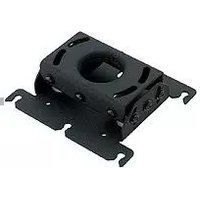
RPA201 - Intercom Chief - Free user manual and instructions
Find the device manual for free RPA201 Chief in PDF.


| Type of Product | Ceiling Mount for LCD/DLP Projectors |
| Brand | Chief |
| Model | RPA201 |
| Compatible Projectors | Inverted LCD/DLP projectors |
| Construction Material | Heavy gauge steel |
| Mounting Methods | 1 1/2" NPT pipe, flush to wood framing, threaded rods |
| Adjustment Capabilities | Roll, pitch, yaw |
| Quick Disconnect | Yes, via thumb nuts without loss of registration |
| Cable Management | Integrated cable routing |
| Security Option | All-Points™ Security kit included (security screws) |
| Ventilation | Designed to ensure proper projector ventilation |
| Lamp Change Access | Allows access for quick lamp changes without disassembly |
| Filter Cleaning | Easy filter cleaning without disassembly |
| Profile | Low profile design |
| Weight Capacity | Ceiling structure must support 5x total equipment weight |
| Installation Tools Included | Allen wrench, security Allen wrench |
| Included Parts | Ceiling bracket, joint bracket, adjustment plate, screws |
| Product Dimensions | Not specified in manual; refer to dimensional drawing |
| Warranty | Not specified |
Frequently Asked Questions - RPA201 Chief
User questions about RPA201 Chief
0 question about this device. Answer the ones you know or ask your own.
Ask a new question about this device
Download the instructions for your Intercom in PDF format for free! Find your manual RPA201 - Chief and take your electronic device back in hand. On this page are published all the documents necessary for the use of your device. RPA201 by Chief.
USER MANUAL RPA201 Chief
RPA Series LCD/DLP Ceiling Mount
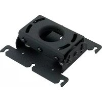
The Chief RPA Series ceiling mounts provide a unique, simplified method of ceiling mounting inverted LCD/DLP projectors. Chief's low profile design offers three easy mounting methods (1 1/2"NPT, flush or threaded rod); roll, pitch and yaw adjustment; a cable management system; and custom designed brackets that allow quick projector disconnect without loss of registration.
All Chief RPA Series ceiling mounts provide access for quick lamp changes and easy filler cleaning without requiring any disassembly. The mount is constructed of heavy gauge steel and designed to ensure proper projector ventilation.
Fast and precise image registration is achieved through the easy roll, pitch and yaw adjustments built into the RPA mounts. Optional projector security is included by using the All-Points™ Security kit
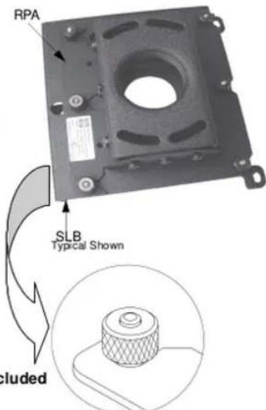
All-Points™ Security Option Included
Chief's Exclusive quick-disconnect thumbnut

IMPORTANT WARNINGS AND CAUTIONS!
WARNING: A WARNING alerts you to the possibility of serious injury or death if you do not follow the instructions.
CAUTION: A CAUTION alerts you to the possibility of damage or destruction of equipment if you do not follow the corresponding instructions.
- WARNING: Improper installation can result in serious personal injury! Make sure that the ceiling structural members can support a redundant weight factor five times the total weight of the equipment. If the ceiling can not support this weight, reinforce the ceiling before installing the RPA.
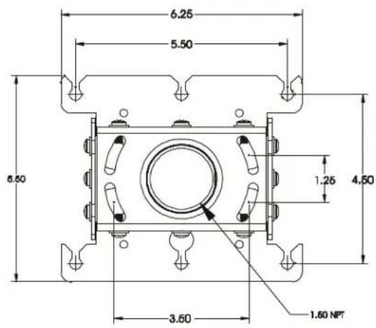
- CAUTION: Inspect the unit for shipping damage. See “DIMENSIONAL DRAWING” on page 3
TOOLS REQUIRED FOR INSTALLATION
- Allen Wrench (provided)
• Security Allen Wrench (provided)
• Phillips screwdrivers, No. 1 and No. 2
NOTE: Other tools may be required depending on the method of installation.
CONTENTS
DIMENSIONAL DRAWING 3
INSPECT THE UNIT BEFORE INSTALLING .... 4
PREPARE THE CEILING .... 4 General Guidelines .... 4
RPA INSTALLATION PROCEDURES .... 5 1 1/2" Diameter NPT Threaded Pipe .... 5 Standard Fasteners Secured to a Wood Framing Member .... 6 Threaded Rod .... 6
BRACKET ATTACHMENT PROCEDURES ... 7 ALL-POINTS SECURITY .... 7
PROJECTOR ALIGNMENT INSTRUCTIONS ....8 Pitch ....8 Roll ....8 Yaw ....8
PARTS 9
DIMENSIONAL DRAWING


INSPECT THE UNIT BEFORE INSTALLING
- Carefully inspect the RPA for shipping damage. If any damage is apparent, call your carrier claims agent and do not continue with the installation until the carrier has reviewed the damage.
NOTE: Read all instructions before starting installation.
- Lay out components to ensure you have all the required parts before proceeding (see "PARTS" on page 9).
PREPARE THE CEILING
Because of the wide variety of possible mounting situations, Chief Manufacturing can only provide general guidelines for installation. Study the following information carefully, and adapt it as necessary to fit your specific installation.
WARNING: Be especially aware of the weight of the equipment, and the potential for personal injury or of damage to the equipment if it is not adequately mounted.
The “General Guidelines” below and the information on the following pages cover the most common mounting situations:
- Suspended from a 1 1/2" diameter NPT threaded pipe secured to a structural cross brace in the ceiling.
- Standard fasteners secured to a wood framing member.
- Suspended from threaded rods that are secured to the structural cross brace
General Guidelines
- Carefully determine the position of the mount, and its distance from the screen. This will require knowing the lens to screen distance (see projector specifications for set-up).
WARNING: Improper installation can result in serious personal injury! To avoid such injury, make sure that the ceiling structural members can support a redundant weight factor five times the total weight of the equipment you intend to support overhead. If they cannot, the ceiling must be reinforced before you install the mount.
RPA INSTALLATION PROCEDURES
There are three methods for installing the RPA Series LCD/DLP ceiling mount. The RPA can be suspended from a 1 1/2" diameter NPT threaded pipe, standard fasteners secured to a wood framing member, or threaded rods.
WARNING: Improper installation can cause serious personal injury! Make sure that the ceiling structural members can support a redundant weight factor five times the total weight of the equipment you intend to support overhead. The ceiling must be reinforced before you install the RPA if the ceiling cannot support a redundant weight factor five times the total weight of the equipment.
1 1/2" Diameter NPT Threaded Pipe
Installation using a 1 1/2" diameter schedule 40 steel pipe section with 1 1/2" NPT threads requires securing the pipe to the building structure. We suggest the use of a Chief CMA ceiling plate to secure the pipe to a structural member (see Figure 1 and Figure 2). Install the RPA on the pipe as follows:
- Thread the RPA onto the pipe a minimum of 1/2" to allow for final yaw adjustment.
- Using Allen wrench provided, tighten the set screw to lock the RPA in position (see Figure 3).
- Proceed to "BRACKET ATTACHMENT PROCEDURES" on page 7.
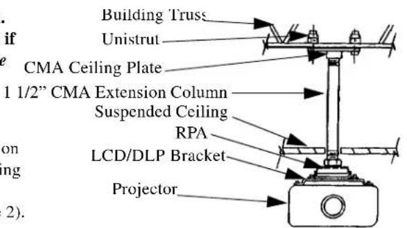
Figure 1. Example Using Pipe (1 1/2")
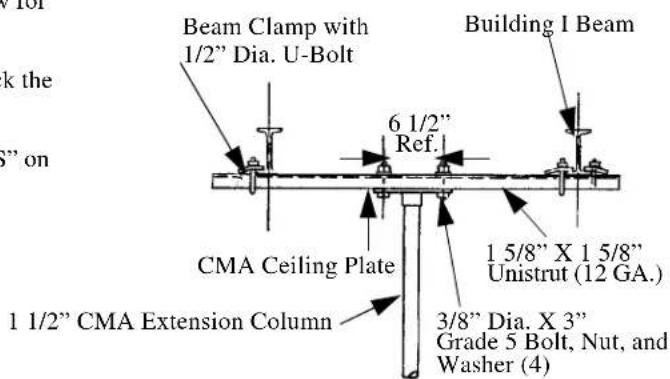
Figure 2. Pipe (1 1/2") Side View
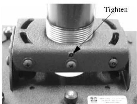
Figure 3. Tighten Set Screw
Standard Fasteners Secured to a Wood Framing Member
The RPA can be secured to a wood framing member through four slotted holes in the ceiling bracket using four 1/4" diameter lag screws or, if the area is accessible from above, four 1/4" diameter machine bolts, nuts, and washers (see Figure 4). Install the RPA as follows:
-
Secure the ceiling bracket to the wood framing member.
-
Proceed to "BRACKET ATTACHMENT PROCEDURES" on page 7.
Threaded Rod
Using four 1/4" diameter threaded rods, the RPA can be secured to a typical unistrut, angle or channel assembly at the overhead structural members (trusses or I-beams) (see Figure 5 and Figure 6). Install the RPA as follows:
- Secure one end of the threaded rod to the structural member.
- Install a 1/4-20 jam nut on each threaded rod.
- Install the RPA on the threaded rod.
NOTE: Holes in the RPA allow socket wrench access without unit disassembly.
- Secure the RPA to the threaded rod using four 1/4-20 nuts.

Figure 4. Example Using Lag Bolts or Machine Bolts

Figure 5. 1/4"Threaded Rod (Front View)

Figure 6. 1/4"Threaded Rod (Side View)
BRACKET ATTACHMENT PROCEDURES
All LCD/DLP brackets attach to the RPA by sliding the screws of the bracket into the one enclosed slot and five vee slots of the RPA. Secure the bracket using provided thumb screws (see Figure 7) and route cabling as necessary. Install the RPA on the bracket as follows:
NOTE: It is not necessary to remove the thumb nuts from the studs.
-
Loosen the 10-24 thumb nuts.
-
Align the locating slot and five vee slots of the RPA with the 10-24 studs of the bracket and slide the bracket on the RPA to the limit of the slotted holes.
NOTE: The tapers of the thumb nuts should seat in the holes of the bracket.
-
Secure the Bracket to the RPA using the thumb nuts (tapered side down).
-
Route cables as necessary (see Figure 8).
ALL-POINTS™ SECURITY
Install All-Points security as follows:
- Remove four screws (A thru D) (see Figure 9).
NOTE: You must retain the Security Allen Wrench if security screws are installed. Do not discard this wrench or leave it where unauthorized persons have access to your Security Allen Wrench.
-
Using security wrench (provided), replace screws (A thru D) with security screws.
-
Using security wrench (provided), remove 5/16" standard set screw (E) and replace with 5/16" security set screw.
-
Remove two screws from SLB, preferably one from each far corner (see Figure 10).
-
Using security wrench (provided), replace screws in SLB with undercut security screws (see Figure 11).
-
Remove all projector mounting screws and, using security wrench (provided), replace projector mounting screws with security screws.

Figure 7. RPA to Bracket Attachment

Figure 8. Cable Routing Example

Figure 9. Remove and Replace Screws and Set Screw

Figure 10. Remove Adjacent Screws

Figure 11. Security Screws
PROJECTOR ALIGNMENT INSTRUCTIONS
The RPA can be adjusted for vertical elevation (pitch), horizontal tilt (roll), and rotation (yaw). Once the desired position is located and all the screws of the RPA are tightened, the projector may be removed from its location and replaced using the six thumb screws without loosing the registration of the projector. Align the projector as follows:
Pitch
Adjust pitch using the two 10-24X3/8" pitch adjustment screws located on each side of the adjustment plate. Adjust pitch as follows:
- Loosen two 10-24X3/8" pitch adjustment screws located on each side of the adjustment plate (see Figure 12).
- Adjust projector angle to desired pitch.
- Tighten two 10-24X3/8" pitch adjustment screws located on each side of the adjustment plate.
Roll
Adjust roll using the four 10-24X3/8" roll adjustment screws, two on the front and three on the back, of the adjustment plate. Adjust roll as follows:
- Loosen two 10-24X3/8" roll adjustment screws on each side of the adjustment plate (see Figure 13).
- Adjust projector to desired roll position.
- Tighten two 10-24X3/8" roll adjustment screws on each side of the adjustment plate.
Yaw
Adjust yaw by threading or unthreading the RPA on the 1 1/2" pipe. Adjust yaw as follows:
- Loosen the set screw (see Figure 14).
WARNING: Do not turn the RPA to the end of the pipe threads. The RPA, bracket, and projector will fall from the pipe if the RPA is unthreaded too far. - Adjust projector by turning the RPA on the 1 1/2" pipe to the desired yaw position.
- Tighten the set screw.

Figure 12. Pitch Adjustment

Figure 13. Roll Adjustment

Figure 14. Yaw Adjustment
PARTS

Table 1: Parts
| No. | Nomenclature Qty. | |
| 1 | BRACKET, Ceiling | 1 |
| 2 | BRACKET, Joint | 1 |
| 3 | PLATE, Adjustment | 1 |
| 4 | SCREW, Self-Tapping, Pan Head, 10-24 X 1/2”, with washer | 12 |
| 5 | SCREW, Set, 5/16” | 1 |


- RPA SERIES LCD/DLP CEILING MOUNT
- IMPORTANT WARNINGS AND CAUTIONS
- TOOLS REQUIRED FOR INSTALLATION
- CONTENTS
- DIMENSIONAL DRAWING
- INSPECT THE UNIT BEFORE INSTALLING
- PREPARE THE CEILING
- GENERAL GUIDELINES
- RPA INSTALLATION PROCEDURES
- 1 1/2" DIAMETER NPT THREADED PIPE
- STANDARD FASTENERS SECURED TO A WOOD FRAMING MEMBER
- THREADED ROD
- BRACKET ATTACHMENT PROCEDURES
- ALL-POINTS™ SECURITY
- PROJECTOR ALIGNMENT INSTRUCTIONS
- PITCH
- ROLL
- YAW
Brand : Chief
Model : RPA201
Category : Intercom