
TH-PS-D - Wall panel support Atdec - Free user manual and instructions
Find the device manual for free TH-PS-D Atdec in PDF.

| Product Type | Wall Mount for Projector |
| Brand | Atdec |
| Model | TH-PS-D |
| Maximum Load Capacity | 25 kg (55 lbs) |
| Adjustable Angle (Support Arm) | ±5° for wall slope compensation |
| Compatible Projector Mount | Atdec TH-PF series (installation continued) |
| Material | Metal (steel/aluminum) |
| Cable Management | Integrated cable cover and base cover with slot |
| Wall Plate Fixing | Masonry or timber stud using coach screws and nylon anchors |
| Tools Required | Power drill, 6mm & 12mm drill bits, 13mm socket wrench, Phillips screwdriver |
| Included Hardware | 6 coach screws, 6 nylon anchors, 6 washers, 2 security screws, 3mm security Allen key |
| Installation Steps | 8 steps including wall plate mounting, arm attachment, cover fitting |
| Security Features | Security screws and Allen key to prevent unauthorized removal |
| Maintenance | Clean with a soft, damp cloth; check tightness periodically |
| Safety Warning | Ensure wall structure supports total weight; consult engineer if unsure |
| Spare Parts Availability | Contact Atdec for replacement hardware or covers |
Frequently Asked Questions - TH-PS-D Atdec
User questions about TH-PS-D Atdec
0 question about this device. Answer the ones you know or ask your own.
Ask a new question about this device
Download the instructions for your Wall panel support in PDF format for free! Find your manual TH-PS-D - Atdec and take your electronic device back in hand. On this page are published all the documents necessary for the use of your device. TH-PS-D by Atdec.
USER MANUAL TH-PS-D Atdec
Tools Required:
- Power Drill
- 6mm(0.23") Drill Bit
• 12mm(0.47") Masonry Drill Bit
• 13mm (0.5") Socket Wrench Shifter
• Phillips Head Screwdriver
HARDWARE

Coach Screw (x6)
Nylon Anchor (x6)

Washer (x6)

Security Screw (x2)

3mm Security Allen Key
IMPORTANT INFORMATION:
! IMPORTANT - Install Telehook Short Throw Projector Mount as per installation instruction.
! This product supports a maximum load of 25kg (55lbs.).
! The manufacturer accepts no responsibility for incorrect installation.
Step 1. Check Components
Check you have received against the component checklist and hardware above.
Step 2. Position Central Connector
Select the position of the Central Connector before mounting the Wall Plate to the wall.

natural_image
Technical diagram of a mechanical assembly with directional arrows indicating movement or force (no text or symbols present)Step 3. Mounting Wall Plate
Masonary Timber Stud

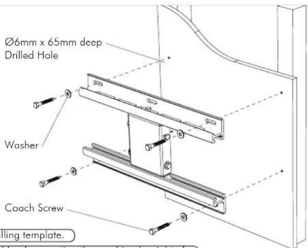
TIP: Use Mount as a drilling template.
IMPORTANT! Any structural elements must be capable of supporting the combined weight of all the equipment and devices being mounted. If in doubt, consult a structural engineer.
Step 4. Insert Covers and Extrusion onto Wall Plate
Step 5. Remove End Cap, Sliding Pole Mount, Base Cover and Cable Cover from Support Arm
5.1. Remove screw from End Cap and slide End Cap off
5.2. Loosen screws on Sliding Pole Mount and slide the entire assembly off
5.3. Slide off Base Cover
5.4. Slide the Cable Cover out

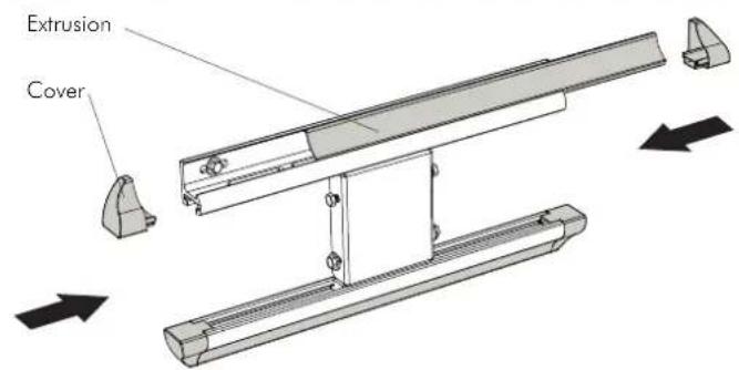
Step 6. Attach Support Arm to Wall Mount
6.1.
natural_image
Mechanical bracket assembly diagram with no visible text or symbolsSlide the hook on the Support Arm over the top bolts on the Wall Plate.
6.2.
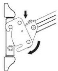
natural_image
Mechanical linkage diagram showing a lever mechanism with rotational motion indicated by arrows (no text or symbols)Swing the Support Arm down so the bottom slots slide over the bottom bolts.
6.3.
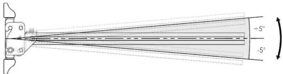
The Support Arm can be adjusted by + / - 5^ to account for wall slope or individual projector characteristics.
6.4.
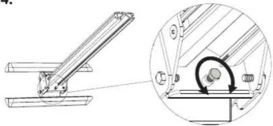
natural_image
Technical diagram of a mechanical assembly with an inset showing a circular component being inserted into a bracket (no text or symbols present)Adjust the stop bolt as shown to maintain the desired angle.
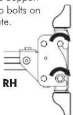
6.5.

Secure the position of the Support Arm by tightening the two bolts on each side of the Wall Plate.
Step 7. Re-Attach Covers and Cable Cover
7.1.

Insert cable through Cable Cover and slide onto the Support Arm.
7.2.
Break the Base Cover tab on the side to allow the cable to exit through slot.
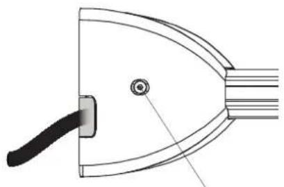
natural_image
Technical line drawing of a curved mechanical component with a handle and central hole (no text or symbols)Secure the Base Cover with the corresponding Security Screws.
7.3.
The Cable Cover may need to be cut to length depending on where the projector is positioned along the Support Arm. After the appropriate length has been attained, slide cover back on. Please refer to your projector documentation for guidance on Focal Length/Throw.

natural_image
Technical line drawing of a mechanical assembly with two circular components and a central shaft (no text or symbols)7.4.
Re-mount the Sliding Pole Mount with the cable fitted either in Option A or B. This will depend on the projector, projector mount and position of the cable socket.
Option A

natural_image
Pure mechanical component diagram without any text, numbers, or symbolsOption B
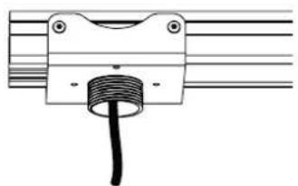
natural_image
Pure mechanical component diagram without any text, numbers, or symbols7.5.
Reinsert the End Cap and secure with the corresponding screw.

natural_image
Technical line drawing of a mechanical assembly with no visible text or symbolsStep 8. Attach Projector Mount
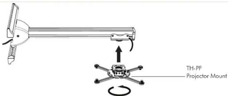
To complete installation please jump to Step 5 of TH-PF installation manual.
Brand : Atdec
Model : TH-PS-D
Category : Wall panel support