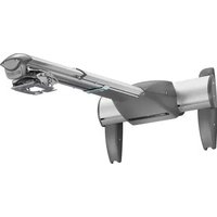
WM220AUSI - Washing machine Chief - Free user manual and instructions
Find the device manual for free WM220AUSI Chief in PDF.


| Product Type | Short Throw Projector Wall Mount |
| Model | WM220AUSI (Interactive Version) |
| Brand | Chief |
| Maximum Weight Capacity | 25 lbs (11.3 kg) |
| Compatible Wall Types | Wood studs (2x4, 16" OC), steel studs (min 25 ga), concrete, concrete block |
| Drywall Thickness | Wood studs: max 5/8"; Steel studs: min 1/2" |
| Adjustments | Pitch (tilt), Extension (depth), Lateral shift |
| Interactive Functionality | Yes (model AUSI includes interactive cartridge for whiteboard use) |
| Active Capture Area | Max: 4 ft x 7 ft (94" diagonal); Min: 1.7 ft x 1.1 ft |
| System Requirements (Interactive) | Windows: Pentium II 400 MHz, 256 MB RAM, USB; Mac: PowerPC/Intel 1.42 GHz, 1 GB RAM, USB |
| USB Port Power | 5V, 0.2A max |
| Mounting Hardware Included | Wall bracket, projector mounting plate, concrete anchors, lag screws, steel stud anchors, covers, security screws (optional) |
| Projector Interface | Compatible with Chief RPM, RPA, RSA, RSM (RSM included with AUSI models) |
| Cable Management | Integrated cable clips and covers; optional cable ties |
| Safety Certifications | UL Listed |
| Warranty | Standard Chief warranty (refer to manufacturer) |
Frequently Asked Questions - WM220AUSI Chief
User questions about WM220AUSI Chief
0 question about this device. Answer the ones you know or ask your own.
Ask a new question about this device
Download the instructions for your Washing machine in PDF format for free! Find your manual WM220AUSI - Chief and take your electronic device back in hand. On this page are published all the documents necessary for the use of your device. WM220AUSI by Chief.
USER MANUAL WM220AUSI Chief
INSTALLATION INSTRUCTIONS

natural_image
Technical line drawing of a mechanical component labeled WM-210SI (no other text or symbols)
natural_image
Technical line drawing of a mechanical component labeled WM-220SI (no other text or symbols)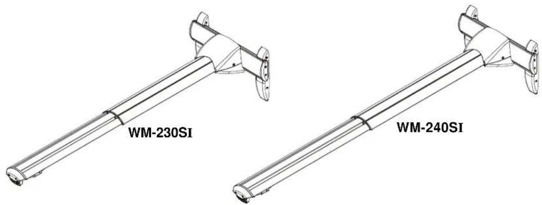
Dual Stud Short Throw Wall Mounts
DISCLAIMER
Milestone AV Technologies and its affiliated corporations and subsidiaries (collectively "Milestone"), intend to make this manual accurate and complete. However, Milestone makes no claim that the information contained herein covers all details, conditions or variations, nor does it provide for every possible contingency in connection with the installation or use of this product. The information contained in this document is subject to change without notice or obligation of any kind. Milestone makes no representation of warranty, expressed or implied, regarding the information contained herein. Milestone assumes no responsibility for accuracy, completeness or sufficiency of the information contained in this document.
Chief® is a registered trademark of Milestone AV Technologies. All rights reserved.

IMPORTANT SAFETY INSTRUCTIONS

WARNING: A WARNING alerts you to the possibility of serious injury or death if you do not follow the instructions.

CAUTION: A CAUTION alerts you to the possibility of damage or destruction of equipment if you do not follow the corresponding instructions.

WARNING: Failure to read, thoroughly understand, and follow all instructions can result in serious personal injury, damage to equipment, or voiding of factory warranty! It is the installer's responsibility to make sure all components are properly assembled and installed using the instructions provided.

WARNING: Failure to provide adequate structural strength for this component can result in serious personal injury or damage to equipment! It is the installer's responsibility to make sure the structure to which this component is attached can support five times the combined weight of all equipment. Reinforce the structure as required before installing the component. The wall to which the mount is being attached may have a maximum drywall thickness of 5/8" (15.9mm) for wood studs; and a minimum drywall thickness of 1/2" (12.7mm) for steel studs.

WARNING: Use this mounting system only for its intended use as described in these instructions. Do not use attachments not recommended by the manufacturer.

WARNING: Never operate this mounting system if it is damaged. Return the mounting system to a service center for examination and repair.

WARNING: Do not use this product outdoors.

WARNING: Exceeding the weight capacity can result in serious personal injury or damage to equipment! It is the installer's responsibility to make sure the combined weight of all components attached to the short throw projector mounts do not exceed the mounting system's weight capacity. (See Table 1)
- The weight capacity of the short throw projector mounts may be LIMITED to the lowest weight capacity of any other component or accessory used within the mounting system!
IMPORTANT ! : The short throw projector mounts are designed to be mounted to an 8" concrete, 8"x8"x16" concrete block, 2" x 4" wood studs (16" on center), or 2" x 4"-25ga minimum steel studs wall.
--SAVE THESE INSTRUCTIONS--
Table 1: Weight Capacities
| Model Maximum Weight Capacity of Mounting System | |
| WM210S | .7 kg) |
| WM220S | .7 kg) |
| WM230S | .3 kg) |
| WM240S | .3 kg) |
| WM210AUS | (11.3 kg) |
| WM220AUS | (11.3 kg) |
| WM230AUS | (11.3 kg) |
| WM240AUS | (11.3 kg) |
| WM210SI | .7 kg) |
| WM220SI | .7 kg) |
| WM230SI | .3 kg) |
| WM240SI | .3 kg) |
| WM210AUSI | (11.3 kg) |
| WM220AUSI | (11.3 kg) |
| WM230AUSI | (11.3 kg) |
| WM240AUSI | (11.3 kg) |
TABLE OF CONTENTS
Disclaimer 2
Important Safety Instructions .... 2
Table of Contents 3
Dimensions 4
Legend 5
Parts 6
Site Requirements for Steel Stud (All Models) .. 7
WM2XXSI/WM2XXAUSI Interactive Mount Only . 8
INSTALLATION (All Models) 10
Mounting Wall Bracket 10
Installation to Wall Bracket 12
Projector Installation 13
WM2XXSI/WM2XXAUSIINTERACTIVEMOUNT..14
Installing Mount Covers 14
Cable Management (Optional) ..... 15
Removing Mount Covers .... 15
Installation of Wall Bracket Covers ..... 17
Adjustments 18
Security Screw Installation (Optional) ..... 19
WM2XXS/WM2XXAUS STANDARD MOUNT..21
Installing Mount Covers 21
Cable Management (Optional) 22
Removing Mount Covers .... 22
Installation of Wall Bracket Covers ..... 23
Adjustments 24
Security Screw Installation (Optional) ..... 25
NOTE: WM210S/SI, WM220S/SI, WM230S/SI and
WM240S/SI are required to use UL Listed accessories
[projector interfaces--Models RPM, RPA, RSM or RSA
(not included)] in order to complete the mounting
system. UL Listed RSM is included with
WM210AUS/AUSI, WM220AUS/AUSI, WM230AUS/
AUSI and WM240AUS/AUSI.
DIMENSIONS

![240SI, 45.5" MIN - 70.40" MAX 230SI, 34.11" MIN - 59.58" MAX 220SI, 22.11" MIN - 35.58" MAX 210SI, 15.86" MIN - 23.08" MAX 240SI, TRAVEL 37.2" - 65.6" 230SI, TRAVEL, 29.5" - 54.5" 220SI, TRAVEL 17.5" - 30.25" 210SI, TRAVEL 12.75" - 19.5" [102.87] 4.05 ±3° OF LEVELING ADJUSTMENT [148.43] 5.84 [498.53] 19.63 5.36 [36.12] 1.42 [27.62] 1.09 CABLE CHANNEL DIMENSIONS THRU ARM DIMENSIONS: [MILLIMETERS] INCHES [19.06] .75 [406.40] 16.00 [8.69] .34 [184.14] 7.25 [274.64] 10.81 [292.85] 11.53](/content/2026/06/1183778/images/267d3fa11458ee064872b93637a98aa8b3ae6840bae8048caedc2f6b83ed6e1c.jpg)
LEGEND
 | Tighten Fastener |
| Apretar elemento de fijación | |
| Befestigungsteil festziehen | |
| Apertar fixador | |
| Serrare il fissaggio | |
| Bevestiging vastdraaien | |
| Serrez les fixations | |
 | Loosen Fastener |
| Aflojar elemento de fijación | |
| Befestigungsteil lösen | |
| Desapertar fixador | |
| Allentare il fissaggio | |
| Bevestiging losdraaien | |
| Desserrez les fixations | |
 | Phillips Screwdriver |
| Destornillador Phillips | |
| Kreuzschlitzschraubendreher | |
| Chave de fendas Phillips | |
| Cacciavite a stella | |
| Kruiskopschroevendraaier | |
| Tournevis à pointe cruciforme | |
 | Open-Ended Wrench |
| Llave de boca | |
| Gabelschlüssel | |
| Chave de bocas | |
| Chiave a punte aperte | |
| Steeksleutel | |
| Clé à fourche | |
 | By Hand |
| A mano | |
| Von Hand | |
| Com a mão | |
| A mano | |
| Met de hand | |
| À la main | |
 | Hex-Head Wrench |
| Llave de cabeza hexagonal | |
| Sechskantschlüssel | |
| Chave de cabeça sextavada | |
| Chiave esagonale | |
| Zeskantsleutel | |
| Clé à tête hexagonale |





TOOLS REQUIRED FOR INSTALLATION

PARTS
| All Models A (1) [Short throw wall mount] (WM220 shown as example only) | (WM2XXAUS/AUSI Models Only) X (1) [RSM] Y (1) [SSMU interface bracket] | (WM2XXS/WM2XXAUS Models Only) AJ (1) [Upper cover] AK (1) [Lower cover] |
![(WM2XXSI/WM2XXAUSI Interactive Models Only) X (1) [Cover-top] Y (1) [Interactive cover] Quick Start Guide Z (1) 5/32" (security) AA (4) 8-32 x 3/8" (security) AB (4) 8-32 x 3/8" AE (1) [Stylus] AC (1) [Interactive software] AD (1) [AAA battery] AF (4) [Stylus replacement tips] AG (1) [Stylus wrist strap kit] AH (1) [Interactive USB cable] Interactive Software Guide All Models B (1) [wall bracket] C (2) [wall bracket top cap] D (2) [wall bracket bottom cap] E (2) 1/4-20 x 5/8" F (10) #8-32 x 1/2" G (4) 1/4-20 x 3/8" H (4) 1/4-20 x 1-1/2" J (4) #10-24 x 1-3/8" K (4) [concrete anchor] L (4) 5/16 x 2-1/2" M (6) 5/16" N (4) 1/4-20 x 1-3/4" P (4) 1/4-20 Q (4) 1/4" R (1) 3/16" S (4) #10-24 x 3/8" T (2) 1/4-20 x 1/2" (security) U (4) 1/4-20 x 3/4" (security) V (10) #8-32 x 1/2" (security) W (1) 5/32" (security)](/content/2026/06/1183778/images/4b9e8cf80b1e414874d245fad43ecccbf32f134cbd638bc526abc8c56e44ad6e.jpg)
SITE REQUIREMENTS - Steel Stud Structure (All Models)

WARNING: IMPROPER INSTALLATION CAN LEAD TO EQUIPMENT FALLING CAUSING SERIOUS PERSONAL INJURY OR DAMAGE TO EQUIPMENT! The figure below identifies the minimum requirements for installation of display mounts onto a steel stud structure. If the structure or its components do not meet these requirements contact the mount manufacturer for specific instructions before attempting installation. It should also be noted that no other equipment should be mounted to the same stud. (See Figure 1)
![16" (on center) Studs Display Mount Installation Location (Must be centered on stud) If back side of wall is unfinished, drywall must be installed to a minimum of one stud left and right of the stud(s) being used to install the mount. Drywall must be secured to studs with screws 12" on center. There must be a minimum of 1-7/8" (48mm) clearance inside wall FRONT Drywall **1/2" minimum Drywall Thickness (Both Sides of Stud) **See hazard statement on page 2! Steel Stud (2 x 4 / 25ga minimum) Stud type and structural strength must conform to the North American Specification for the Design of Cold-Formed Steel Structural Members. [362, 125 18, C-Shape, S - Stud Section]](/content/2026/06/1183778/images/a04243caf5f4c14c93cbbebde4578a6e17101708397af16397b0be9409e67a3a.jpg)
Figure 1
WS2XXSI/WS2XXAUSI INTERACTIVE MODELS ONLY
The Chief Interactive Mount (WM2XXSI/WM2XXAUSI) works with standard projectors and Windows® and Macintosh® computers. The Interactive Mount will transform existing whiteboards or other hard, flat surfaces, into interactive whiteboards and allows users to present, annotate, and interact with their projected content and all of their desktop applications.
IMPORTANT ! : After adding batteries to the stylus (AE), tighten the cap only to the point of being fingertip-tight. Overtightening cap may cause the stylus to stop transmitting signals.
Minimum System Requirements
- Windows® System
- Compatible PC with Pentium™ II 400 MHz+ processor and 256 MB RAM
- Windows 2000, XP, Server 2003, Vista, or 7
• 30 MB available hard drive space
• Available USB port
- Macintosh® System
• Power PC®/Intel™ 1.42 GHz+ processor and 1G RAM
• Mac OS X 10.5 through 10.6
• 25 MB available hard drive space
• Available USB port
NOTE: Input to the interactive cartridge through the USB connector shall be limited to 5V, 0.2A max.
Active Capture Area Size
- The maximum active capture area supported is: 4 ft x 7 ft or up to 94 inches diagonal measure.
- The minimum active capture area supported is: 1.7 ft x 1.1 ft.
Connection Requirement
- The interactive mount includes a USB cable.
Screen Recording Requirements
(Currently available only on Windows platform.)
- Pentium™ IV processor
• 1.4GHz, with 512MB RAM
Environmental Interference Guide Ultrasound Reflections
General proximity guideline: A distance of 12 feet (approximately 4 meters) between the motion sensor and the eBeam receiver will normally allow good performance with the maximum board size. (See Figure 2)
Interference can be reduced by reducing the size of the projection area.
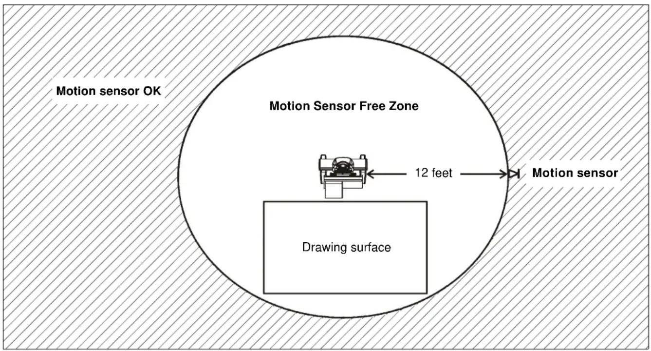
Figure 2
WM2XXSI/WM2XXAUSI Placement and Projection Area Constraints (See Figure 3)
- There should be a minimum distance of 12 inches between the base of the dual mount and the top of the projection image.
- The distance between the base of the dual mount and the bottom corner of the projection image (both right and left) should be less than or equal to 110 inches.
- The projection image should start a minimum of 1 inch from the base of the top frame of the whiteboard.
- The projection image should be positioned within the fan area extending from the Chief Interactive Dual Mount. This fan area should not exceed 140 degrees.
Whiteboard Constraints
- The whiteboard should not be thicker than 1". (See Figure 3)
- The ledge of the whiteboard frame should be less than or equal to 1/3". (See Figure 3)
Important Notes
- Do not put sticky notes, hanging paper, cables, outlets, or other items below the wall mount or inside the capture area. (See Figure 3)
- Image should be placed one inch below the edge of the whiteboard to minimize interference from the frame top.

Figure 3
INSTALLATION - (All Models)
The WM2XXS/SI/AUS/AUSI short throw projector mounts can be mounted to concrete, concrete block, wood studs or steel studs. They can be mounted to 2" x 4" wood studs 16" apart.

WARNING: ELECTRICAL SHOCK HAZARD! CUTTING OR DRILLING INTO ELECTRICAL CORDS OR CABLES CAN CAUSE DEATH OR SERIOUS PERSONAL INJURY! ALWAYS make certain area behind mounting surface is free of electrical wires and cables before cutting, drilling, or installing fasteners.

WARNING: EXPLOSION AND FIRE HAZARD! CUTTING OR DRILLING INTO GAS PLUMBING CAN CAUSE DEATH OR SERIOUS PERSONAL INJURY! ALWAYS make certain area behind mounting surface is free of gas, water, waste, or any other plumbing before cutting, drilling, or installing fasteners.
Mounting Wall Bracket
Concrete or Concrete Block
- Determine mounting location on wall.
- Using wall bracket (B) as a template, mark four holes at the holes in bracket. (See Figure 4)
- Drill four 3/8" holes at marked locations in wall. (See Figure 4)
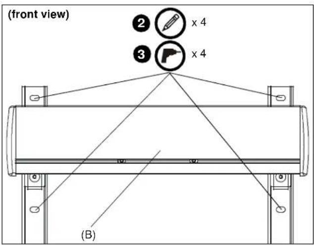
Figure 4
- Install four concrete anchors (K) into drilled holes. (See Figure 5)
- Install four 5/16 x 2-1/2" hex head lag screws (L) through four 5/16" washers (M), outer holes of wall bracket (B) and into concrete anchors (K). (See Figure 5)

Figure 5
Wood Studs

WARNING: The wall to which the mount is being attached may have a maximum drywall thickness of 5/8" (1.6cm).
- Determine mounting location on wall. Use a stud finder to locate 2" x 4" wood studs.
- Line up inner four holes on wall bracket (B) with center of studs at desired mounting location. (See Figure 6)
- Using wall bracket (B) as a template, mark four holes at the holes in bracket. (See Figure 6)
- Drill four 7/32" holes at marked locations in wall. (See Figure 6)
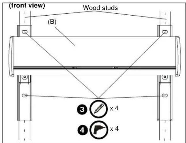
Figure 6
- Install four 5/16 x 2-1/2" hex head lag screws (L) through four 5/16" washers (M), holes of wall bracket and into drilled holes. (See Figure 7)

Figure 7
Steel Studs
IMPORTANT ! : See Site Requirements section before proceeding with Steel Studs installation to ensure installation site meets requirements! The drywall must have a minimum thickness of 1/2"!
- Determine mounting location on wall. Use stud finder to locate steel studs.
- Line up four holes on wall bracket with center of studs at desired mounting location. (See Figure 8)
- Using wall bracket as a template, mark four holes at the inner four holes in bracket. (See Figure 8)
- Drill four 1/2" holes at marked locations in wall. (See Figure 8)

Figure 8
- Hold metal channel on anchor (P) flat alongside plastic straps and slide channel through hole. (See Figure 9)

Figure 9
- Holding plastic straps on anchor (P), pull anchor away from wall until channel rests flush behind wall making sure anchor channel is positioned vertically on stud. (See Figure 10)
- Slide plastic cap on anchor (P) towards wall until flange of cap is flush with wall. (See Figure 10)

Figure 10
-
Snap off plastic straps on anchor at wall by pushing side to side, snapping off straps level with flange of plastic cap. (See Figure 11)
-
Repeat Steps 6 through 8 for each mounting hole.
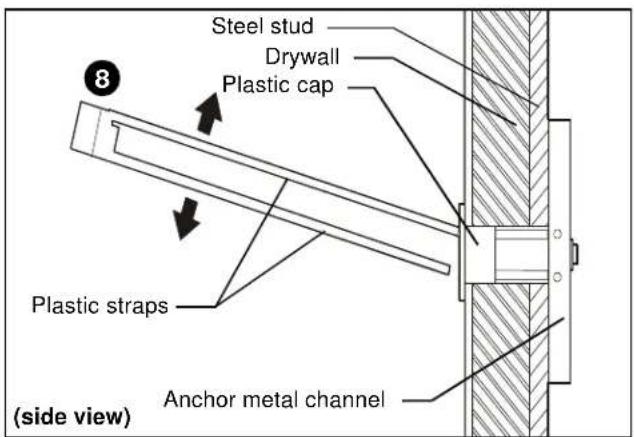
Figure 11
-
Place wall bracket over anchors and align mounting holes in display mount with holes in anchors. (See Figure 12)
-
Insert 1/4-20 x 1-3/4" Phillips pan head screws (N) through 1/4" washer (Q), corresponding mounting hole on wall bracket and into anchor (P) and tighten until flush against mount. DO NOT overtighten! (See Figure 12)
-
Repeat Step 11 for remaining 3 mounting holes.

WARNING: IMPROPER INSTALLATION CAN LEAD TO EQUIPMENT FALLING CAUSING SERIOUS PERSONAL INJURY OR DAMAGE TO EQUIPMENT! Overtightening of mounting hardware can damage the steel studs. DO NOT overtighten mounting hardware!

Figure 12
Installation to Wall Bracket
- Lift short throw projector arm (A) up to wall bracket (B) and hook top plate onto cross bracket on wall bracket. (See Figure 13)
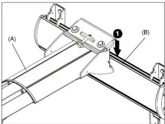
Figure 13
- Slide lower plate onto cross bracket on mounting bracket. (See Figure 14)

Figure 14
- Install two 1/4-20 x 5/8" hex head bolts (E) through holes on short throw projector arm (A) and into sliding nuts on mounting bracket (B). DO NOT TIGHTEN SCREWS AT THIS POINT! (See Figure 15)
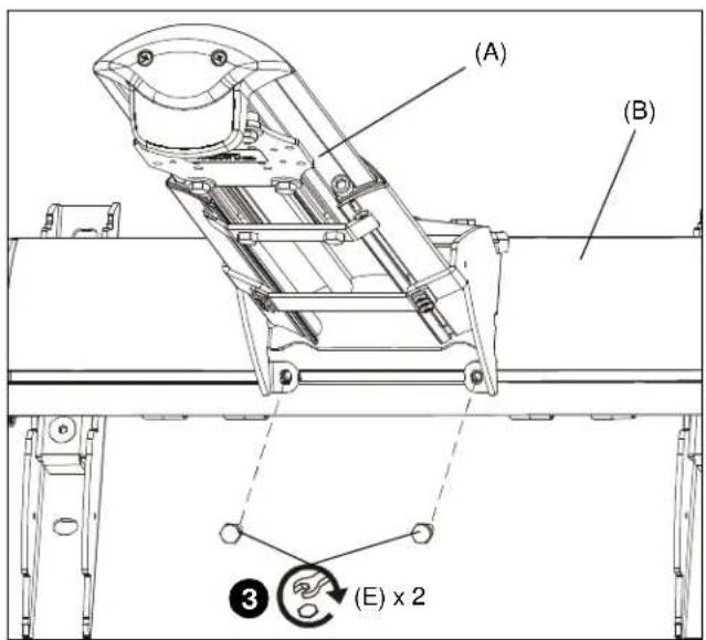
Figure 15
- Loosen two bolts on either side of pitch adjustment screw. (See Figure 16)
- Adjust pitch adjustment screw until mount is at desired pitch level. Turn clockwise to raise mounting level or turn counterclockwise to lower mounting level. (See Figure 16)
- Tighten two bolts on either side of pitch adjustment screw. (See Figure 16)

Figure 16
- Tighten two bolts installed in Step 3. (See Figure 15)
Projector Installation

WARNING: Exceeding the weight capacity can result in serious personal injury or damage to equipment! It is the installer's responsibility to make sure the combined weight of all components attached to the short throw projector mounts do not exceed the mounting system's weight capacity. (See Table 1)
NOTE: UL Listed Chief projector interfaces RPM, RPA and RSA are sold separately. RSM (X) is included with WM2XXAUS/WM2XXAUSI models.

Figure 17
NOTE: Determine hole configuration to use for each specific projector mount. (See Figure 17)
UL Listed RPM Installation
- Line up mounting holes on RPM mount with corresponding holes on projector mounting plate. (See Figure 17)
- Install four 1/4-20 x 1-1/2" Phillips pan machine screws (H) through RPM holes and into projector mounting plate. (See Figure 18)
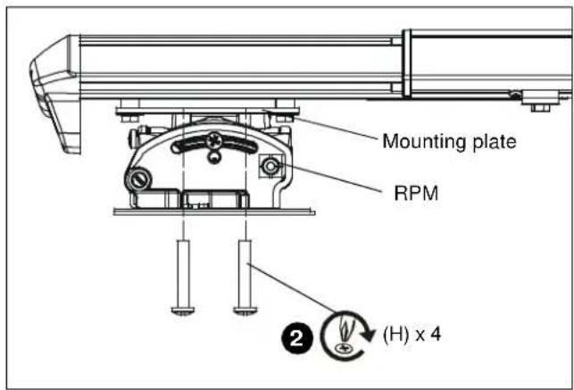
Figure 18
- Install interface and projector to RPM according to RPM and interface bracket installation instructions.
UL Listed RSM Installation (included with WM2XXAUS/AUSI models)
- Line up mounting holes on RSM mount (X) with corresponding holes on projector mounting plate. (See Figure 17)
- Install four #10-24 x 1-3/8" Phillips pan machine screws (J) through RSM holes and into projector mounting plate. (See Figure 19)

Figure 19
- Install interface and projector to RSM according to RSM and interface bracket installation instructions.
UL Listed RPA Installation
- Line up mounting holes on RPA mount with corresponding holes on projector mounting plate. (See Figure 17)
- Install four 1/4-20 x 3/8" Phillips pan machine screws (G) through RPA holes and into projector mounting plate. (See Figure 20)

Figure 20
- Install interface and projector to RPA according to RPA and interface bracket installation instructions.
UL Listed RSA Installation
- Line up mounting holes on RSA mount with corresponding holes on projector mounting plate. (See Figure 17)
- Install four #10-24 x 3/8" Phillips pan machine screws (S) through RSA holes and into projector mounting plate. (See Figure 21)

Figure 21
- Install interface and projector to RSA according to RSA and interface bracket installation instructions.
IMPORTANT ! : Complete the installation by proceeding to WM2XXSI/WM2XXAUSI Interactive Mount section or WM2XXS/WM2XXAUS Standard Mount section, as appropriate.
WM2XXSI/WM2XXAUSI INTERACTIVE MOUNTS
Installing Mount Covers
- Route cables from projector through cartridge in interactive cover (Y). (See Figure 22)

Figure 22
- Connect USB cable (AH) to cartridge through bottom of lower cover.
- Raise the lower cover containing cartridge and attach to wall mount using two 8-32 x 3/8" Phillips pan head screws (AB). (See Figure 23)
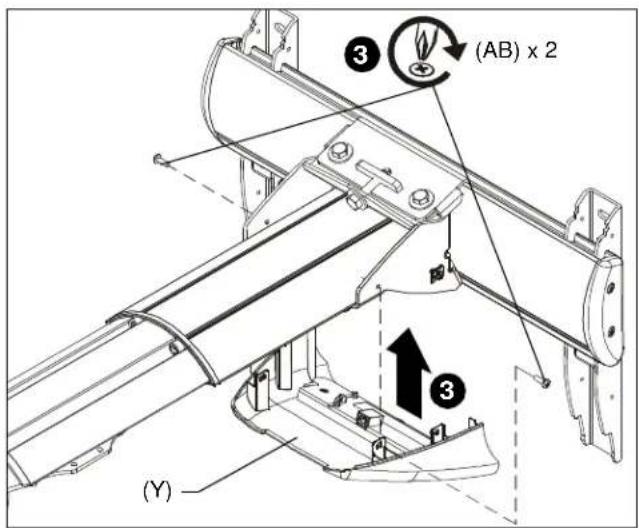
Figure 23
- Lower the upper cover (X) onto the wall mount and lower cover, and fasten with two 8-32 x 3/8" Phillips pan head screws (AB). (See Figure 24)
NOTE: Be sure cables and cords are not pinched between upper and lower covers.
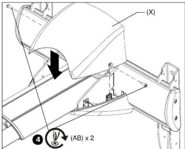
Figure 24
Cable Management (Optional)
In most cases, cable management covers will NOT need to be removed in order to route cables from projector to the wall mount. But for some thick cables, removing the covers may be necessary.
Removing Mount Covers
- Remove and save two 8-32 x 3/8" Phillips pan head screws (AB) from upper cover. (See Figure 25)
- Raise and remove the upper cover from the mount. (See Figure 25)

Figure 25
- Remove and save two 8-32 x 3/8" Phillips pan head screws (AB) from lower cover. (See Figure 26)
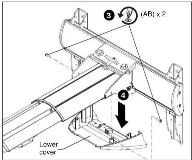
Figure 26
- Remove the lower cover from the wall mount. (See Figure 26)
- Remove cable management covers (if necessary) from short throw projector arm. (See Figure 27)

Figure 27
NOTE: Cables may be routed from below and up wall bracket channel, or from above and down behind and into wall mount.
- Routing Cables from Below (Steps 6 and 7)
- Open cable clips along bottom edge of wall bracket. (See Figure 28)

Figure 28
- Thread cable up wall bracket channel and into opened cable clips. (See Figure 29) Proceed to Step 9

Figure 29
- Routing Cables from Above (Step 8)
- Thread cables down through a surface mount cable accessory (not included), then behind and into the wall bracket. (See Figure 30) Proceed to Step 9

Figure 30
- Route cables through cover mount, projector arm tunnel and into projector. (See Figure 31)
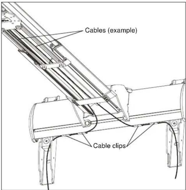
Figure 31
- (Optional) Cables can be tied to inside of mount's front cover using cable ties (not included). Route cables near front cover and wrap cable tie through slots on front cover and around cables. (See Figure 32)

Figure 32
- Replace removed cable management covers (if necessary). Insert one side of cover into groove and press firmly on the cover on the other side until it snaps into the other groove. (See Figure 33)

natural_image
Technical line drawing of a mechanical assembly with directional arrows indicating motion (no text or symbols)Figure 33
- Return outer covers to the mount following instructions in Installing Mount Covers section.
Installation of Wall Bracket Covers
NOTE: If security screws are going to be used, use the security screws (V) to install wall bracket covers. See Security Screw Installation section for details.
- Place wall bracket top caps (C) over top of each wall bracket arm. (See Figure 34)

Figure 34
- Secure wall bracket top caps (C) to wall bracket arms by installing four #8-32 x 1/2" Phillips pan machine screws (F) through holes in covers and wall bracket. (See Figure 35)
- Place wall bracket bottom caps (D) over bottom of each wall bracket arm. (See Figure 34)
- Secure wall bracket bottom caps (D) to wall bracket arms by installing four #8-32 x 1/2" Phillips pan machine screws (F) through holes in covers and wall bracket. (See Figure 35)

Figure 35
Adjustments
Pitch Adjustment
IMPORTANT ! : The mount covers need to be removed before proceeding with pitch adjustment.
NOTE: Remove mount covers from the mount following instructions in Removing Mount Covers section.
- Loosen two 1/4-20 x 5/8" hex head cap screws (E) on underside of mounting bracket. (See Figure 36)

Figure 36
- Loosen two bolts on either side of pitch adjustment screw. (See Figure 37)
- Adjust pitch adjustment screw until mount is at desired pitch level. Turn clockwise to raise mounting level or turn counterclockwise to lower mounting level. (See Figure 37)
- Tighten two bolts on either side of pitch adjustment screw. (See Figure 37)
- Tighten two 1/4-20 x 5/8" screws (E) on underside of mounting bracket. (See Figure 36)
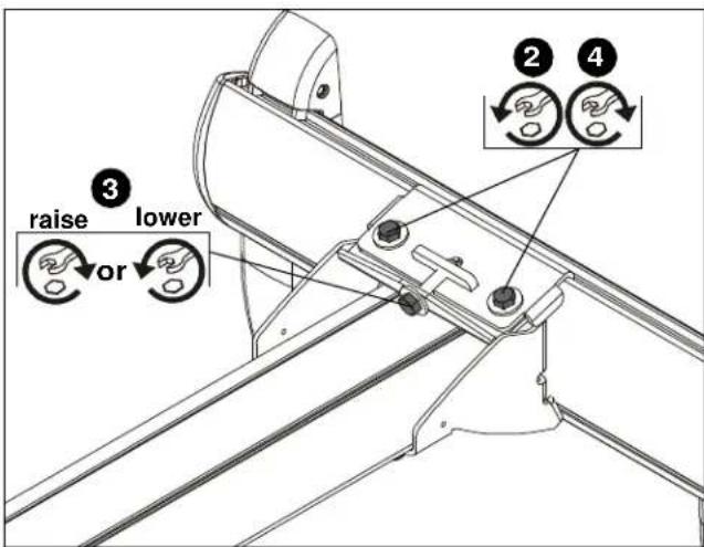
Figure 37
- Return outer covers to the mount following instructions in Installing Mount Covers section.
Extension Adjustment
- Loosen two bolts holding stop bracket in place on underside of short throw projector mount. (See Figure 38)
- Adjust mount to desired extension length. (See Figure 38)
- Tighten two bolts holding stop bracket to secure mount in desired position. (See Figure 38)

Figure 38
Lateral Shift Adjustment
IMPORTANT ! : The mount covers need to be removed before proceeding with lateral shift adjustment.
NOTE: Remove mount covers from the mount following instructions in Removing Mount Covers section.
- Loosen two 1/4-20 x 5/8" hex head cap screws (E) on underside of mounting bracket. (See Figure 39)
- Adjust projector arm laterally to desired position. (See Figure 39)
- Tighten two 1/4-20 x 5/8" hex head cap screws (E) loosened in Step 1. (See Figure 39)
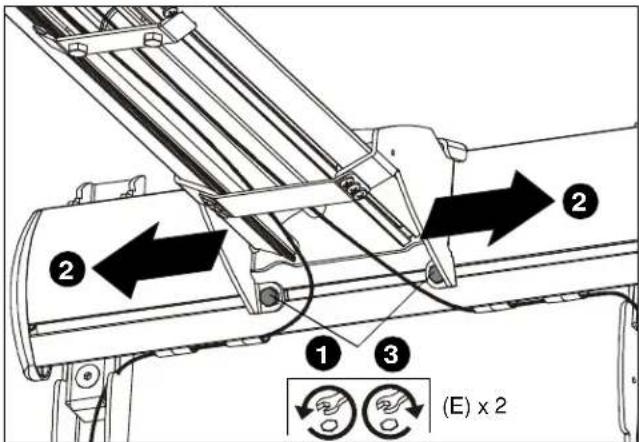
Figure 39
- Return outer covers to the mount following instructions in Installing Mount Covers section.
Security Screw Installation (Optional)
Wall Bracket Covers
- Remove eight #8-32 x 1/2" Phillips pan machine screws (F) from wall bracket covers. (See Figure 40)

Figure 40
- Install eight #8-32 x 1/2" button head security screws (V) into holes in wall bracket covers. (See Figure 41)
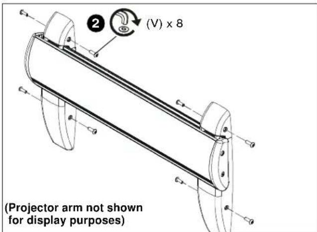
Figure 41
Mount Covers
- Remove two 8-32 x 3/8" Phillips pan head screws (AB) from upper cover. (See Figure 42)
- Raise and remove the upper cover from the mount. (See Figure 42)

Figure 42
- Remove two 8-32 x 3/8" Phillips pan head screws (AB) from lower cover. (See Figure 43)

Figure 43
- Install two 8-32 x 3/8" button head security screws (AA) into lower cover. (See Figure 44)

Figure 44
- Replace upper cover and install two 8-32 x 3/8" button head security screws (AA) into upper cover. (See Figure 45)

Figure 45
Stop Bracket
- Remove two bolts holding stop bracket in place on underside of short throw projector mount. (See Figure 46)

Figure 46
- Install two 1/4-20 x 1/2" button head security screws (T) through holes in stop bracket and into holes in sliding nuts. (See Figure 47)
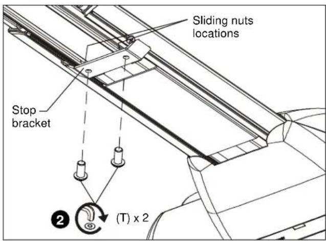
Figure 47
Adapter Plate Bolts
- Remove projector from short throw projector mount according to projector interface instructions.
NOTE: For most projectors, it will be necessary to remove projector prior to installing four security screws to projector bracket. For ease of installation, it is recommended to remove projector prior to performing the following steps.

WARNING: It is important to replace adapter plate bolts
ONE AT A TIME or adapter plate could fall from mount during installation!
- Remove one of four bolts from adapter plate. (See Figure 48)
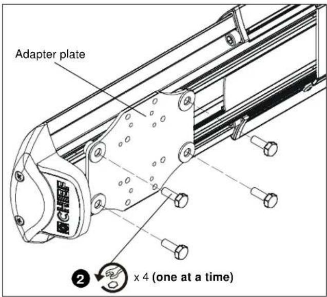
Figure 48
- Install one 1/4-20 x 3/4" button head security screw (U) into hole (vacated by removed bolt in previous step) and into plastic spacer. (See Figure 49)
- Repeat Steps 2-3 for remaining three bolts one bolt at a time.

Figure 49
- Reinstall projector according to interface instructions.
WM2XXS/WM2XXAUS STANDARD MOUNT Installing Mount Covers
- Raise the lower cover (AK) to wall mount and hold in place. (See Figure 50)

Figure 50
- Lower the upper cover (AJ) onto the wall mount and fasten through upper cover (AJ), lower cover (AK) and into wall mount with two 8-32 x 1/2" Phillips pan head screws (F). (See Figure 51)

Figure 51
Cable Management (Optional)
In most cases, cable management covers will NOT need to be removed in order to route cables from projector to the wall mount. But for some thick cables, removing the covers may be necessary.
Removing Mount Covers
- Remove and save two 8-32 x 1/2" Phillips pan head screws (F) from upper cover. (See Figure 52)
- Raise upper cover away from the mount. (See Figure 52)
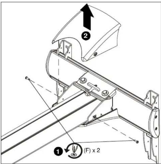
Figure 52
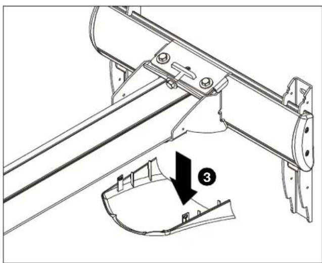
- Remove lower cover from mount. (See Figure 53)
natural_image
Technical line drawing of a mechanical assembly with a numbered component (3), no visible text or symbolsFigure 53
- Remove cable management covers (if necessary) from short throw projector arm. (See Figure 54)

Figure 54
NOTE: Cables may be routed from below and up wall bracket channel, or from above and down behind and into wall mount.
- Routing Cables from Below (Steps 5 and 6)
- Open cable clips along bottom edge of wall bracket. (See Figure 55)

Figure 55
- Thread cable up wall bracket channel and into opened cable clips. (See Figure 56) Proceed to Step 8

Figure 56
- Routing Cables from Above (Step 7)
- Thread cables down through a surface mount cable accessory (not included), then behind and into the wall bracket. (See Figure 57) Proceed to Step 8
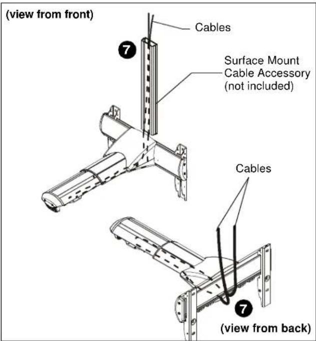
Figure 57
- Route cables through cover mount, projector arm tunnel and into projector. (See Figure 58)

Figure 58
- (Optional) Cables can be tied to inside of mount's front cover using cable ties (not included). Route cables near front cover and wrap cable tie through slots on front cover and around cables. (See Figure 59)

Figure 59
- Replace removed cable management covers (if necessary). Insert one side of cover into groove and press firmly on the cover on the other side until it snaps into the other groove. (See Figure 60)

natural_image
Technical line drawing of a mechanical assembly with directional arrows indicating motion (no text or symbols)Figure 60
- Return outer covers to the mount following instructions in Installing Mount Covers section.
Installation of Wall Bracket Covers
NOTE: If security screws are going to be used, use the security screws (V) to install wall bracket covers. See Security Screw Installation section for details.
- Place wall bracket top caps (C) over top of each wall bracket arm. (See Figure 61)
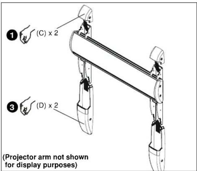
Figure 61
-
Secure wall bracket top caps (C) to wall bracket arms by installing four #8-32 x 1/2" Phillips pan machine screws (F) through holes in covers and wall bracket. (See Figure 62)
-
Place wall bracket bottom caps (D) over bottom of each wall bracket arm. (See Figure 61)
-
Secure wall bracket bottom caps (D) to wall bracket arms by installing four #8-32 x 1/2" Phillips pan machine screws (F) through holes in covers and wall bracket. (See Figure 62)

Figure 62
Adjustments
Pitch Adjustment
IMPORTANT ! : The mount covers need to be removed before proceeding with pitch adjustment.
NOTE: Remove mount covers from the mount following instructions in Removing Mount Covers section.
- Loosen two 1/4-20 x 5/8" hex head cap screws (E) on underside of mounting bracket. (See Figure 63)

Figure 63
-
Loosen two bolts on either side of pitch adjustment screw. (See Figure 64)
-
Adjust pitch adjustment screw until mount is at desired pitch level. Turn clockwise to raise mounting level or turn counterclockwise to lower mounting level. (See Figure 64)
-
Tighten two bolts on either side of pitch adjustment screw. (See Figure 64)
-
Tighten two 1/4-20 x 5/8" screws (E) on underside of mounting bracket. (See Figure 63)

Figure 64
- Return outer covers to the mount following instructions in Installing Mount Covers section.
Extension Adjustment
- Loosen two bolts holding stop bracket in place on underside of short throw projector mount. (See Figure 65)
- Adjust mount to desired extension length. (See Figure 65)
- Tighten two bolts holding stop bracket to secure mount in desired position. (See Figure 65)

Figure 65
Lateral Shift Adjustment
IMPORTANT ! : The mount covers need to be removed before proceeding with lateral shift adjustment.
NOTE: Remove mount covers from the mount following instructions in Removing Mount Covers section.
- Loosen two 1/4-20 x 5/8" hex head cap screws (E) on underside of mounting bracket. (See Figure 66)
- Adjust projector arm laterally to desired position. (See Figure 66)
- Tighten two 1/4-20 x 5/8" hex head cap screws (E) loosened in Step 1. (See Figure 66)

Figure 66
- Return outer covers to the mount following instructions in Installing Mount Covers section.
Security Screw Installation (Optional)
Wall Bracket Covers
- Remove eight #8-32 x 1/2" Phillips pan machine screws (F) from wall bracket covers. (See Figure 67)
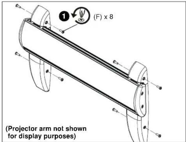
Figure 67
- Install eight #8-32 x 1/2" button head security screws (V) into holes in wall bracket covers. (See Figure 68)
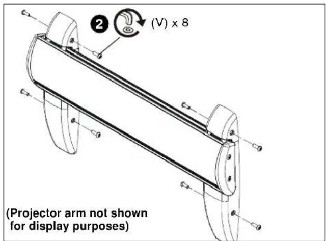
Figure 68
Mount Covers
- Remove two #8-32 x 1/2" Phillips pan machine screws (F) holding mount covers on projector arm. (See Figure 69)
- Install two #8-32 x 1/2" button head security screws (V) into holes on mount cover. (See Figure 69)
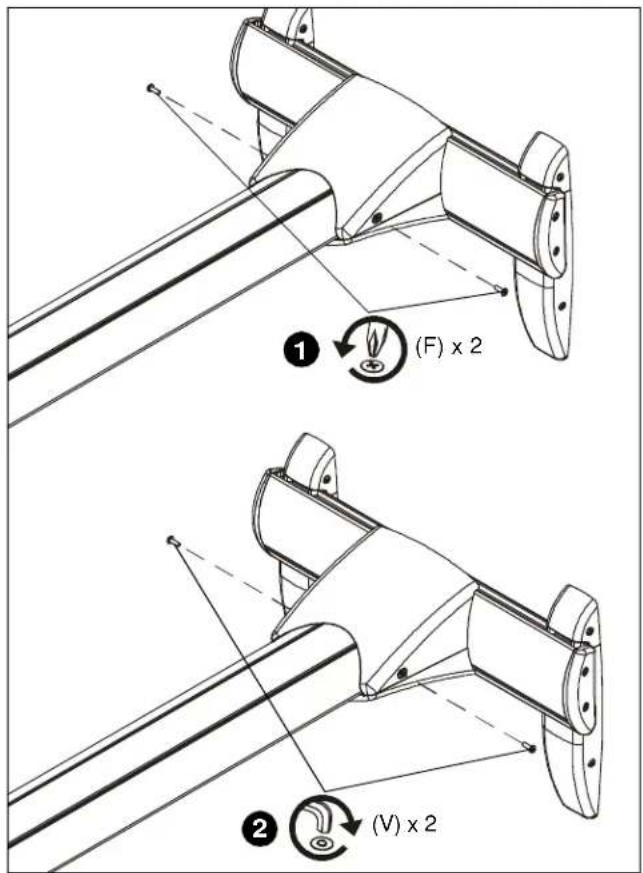
Figure 69
Stop Bracket
- Remove two bolts holding stop bracket in place on underside of short throw projector mount. (See Figure 70)

Figure 70
- Install two 1/4-20 x 1/2" button head security screws (T) through holes in stop bracket and into holes in sliding nuts. (See Figure 71)

Figure 71
Adapter Plate Bolts
- Remove projector from short throw projector mount according to projector interface instructions.
NOTE: For most projectors, it will be necessary to remove projector prior to installing four security screws to projector bracket. For ease of installation, it is recommended to remove projector prior to performing the following steps.

WARNING: It is important to replace adapter plate bolts ONE AT A TIME or adapter plate could fall from mount during installation!
- Remove one of four bolts from adapter plate. (See Figure 72)

Figure 72
-
Install one 1/4-20 x 3/4" button head security screw (U) into hole (vacated by removed bolt in previous step) and into plastic spacer. (See Figure 73)
-
Repeat Steps 2-3 for remaining three bolts one bolt at a time.
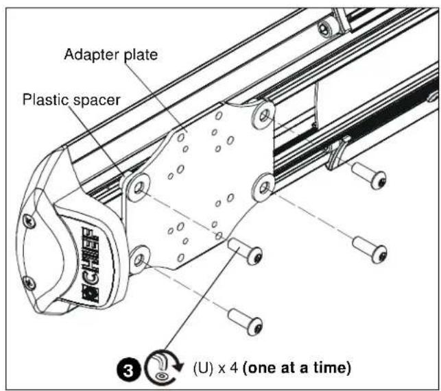
Figure 73
- Reinstall projector according to interface instructions.
Installation Instructions


- INSTALLATION INSTRUCTIONS
- Dual Stud Short Throw Wall Mounts
- DISCLAIMER
- IMPORTANT SAFETY INSTRUCTIONS
- --SAVE THESE INSTRUCTIONS--
- TABLE OF CONTENTS
- WM2XXSI/WM2XXAUSIINTERACTIVEMOUNT..14
- WM2XXS/WM2XXAUS STANDARD MOUNT..21
- SITE REQUIREMENTS - Steel Stud Structure (All Models)
- WS2XXSI/WS2XXAUSI INTERACTIVE MODELS ONLY
- Minimum System Requirements
- Active Capture Area Size
- Connection Requirement
- Screen Recording Requirements
- Environmental Interference Guide Ultrasound Reflections
- WM2XXSI/WM2XXAUSI Placement and Projection Area Constraints (See Figure 3)
- Whiteboard Constraints
- Important Notes
- INSTALLATION - (All Models)
- Mounting Wall Bracket
- Concrete or Concrete Block
- Wood Studs
- Steel Studs
- Installation to Wall Bracket
- Projector Installation
- UL Listed RPM Installation
- UL Listed RSM Installation (included with WM2XXAUS/AUSI models)
- UL Listed RPA Installation
- UL Listed RSA Installation
- WM2XXSI/WM2XXAUSI INTERACTIVE MOUNTS
- Installing Mount Covers
- Cable Management (Optional)
- Removing Mount Covers
- Installation of Wall Bracket Covers
- Adjustments
- Pitch Adjustment
- Extension Adjustment
- Lateral Shift Adjustment
- Security Screw Installation (Optional)
- Wall Bracket Covers
- Mount Covers
- Stop Bracket
- Adapter Plate Bolts
- WM2XXS/WM2XXAUS STANDARD MOUNT Installing Mount Covers
- - Routing Cables from Above (Step 7)
Brand : Chief
Model : WM220AUSI
Category : Washing machine