
K3F120B - Ceiling mount Chief - Free user manual and instructions
Find the device manual for free K3F120B Chief in PDF.


| Product Type | Ceiling Mount (K3 Series) |
| Model | K3F120B |
| Brand | Chief |
| Maximum Weight Capacity | 25 lbs (11.34 kg) per display |
| Number of Displays Supported | Up to 3 (depending on configuration) |
| Material | Steel |
| Finish | Black powder coat |
| Mounting Type | Free-standing (table top) or Grommet mount |
| Adjustment Types | Height, Pivot, Pitch, Roll, Yaw, Lateral Shift (outer displays) |
| Pivot Range | Up to 15° forward per arm (backward pivot not allowed) |
| Height Adjustment Range | Continuous along column (specific range not specified) |
| Display Compatibility | VESA 75x75mm or 100x100mm (via M4 screws) |
| Supplied Screw Sizes | M4x12mm (flush), M4x20mm, M4x30mm (recessed) |
| Base Dimensions (K3F120) | Approx. 12 x 8 inches (estimated) |
| Column Height | Approx. 24 inches (estimated) |
| Product Weight | Approx. 10 lbs (4.5 kg) estimated |
| Power Source | None (passive mount) |
| Maintenance and Cleaning | Wipe with a soft dry cloth; do not use abrasive cleaners |
| Safety Warnings | Must support 5x total weight; do not exceed weight capacity; indoor use only |
| Included Parts | Array assembly, base, cover, column cap, screws, bumpers |
| Spare Parts Availability | Contact Chief customer service for parts |
| Warranty | 10 years (standard Chief warranty) |
Frequently Asked Questions - K3F120B Chief
User questions about K3F120B Chief
0 question about this device. Answer the ones you know or ask your own.
Ask a new question about this device
Download the instructions for your Ceiling mount in PDF format for free! Find your manual K3F120B - Chief and take your electronic device back in hand. On this page are published all the documents necessary for the use of your device. K3F120B by Chief.
USER MANUAL K3F120B Chief
INSTALLATION INSTRUCTIONS

Kontour™ Array Arm Series
DISCLAIMER
Milestone AV Technologies and its affiliated corporations and subsidiaries (collectively "Milestone"), intend to make this manual accurate and complete. However, Milestone makes no claim that the information contained herein covers all details, conditions or variations, nor does it provide for every possible contingency in connection with the installation or use of this product. The information contained in this document is subject to change without notice or obligation of any kind. Milestone makes no representation of warranty, expressed or implied, regarding the information contained herein. Milestone assumes no responsibility for accuracy, completeness or sufficiency of the information contained in this document.
Chief® is a registered trademark of Milestone AV Technologies. All rights reserved.

IMPORTANT SAFETY INSTRUCTIONS

WARNING: A WARNING alerts you to the possibility of serious injury or death if you do not follow the instructions.

CAUTION: A CAUTION alerts you to the possibility of damage or destruction of equipment if you do not follow the corresponding instructions.

WARNING: Failure to read, thoroughly understand, and follow all instructions can result in serious personal injury, damage to equipment, or voiding of factory warranty! It is the installer's responsibility to make sure all components are properly assembled and installed using the instructions provided.

WARNING: Failure to provide adequate structural strength for this component can result in serious personal injury or damage to equipment! It is the installer's responsibility to make sure the structure to which this component is attached can support five times the combined weight of all equipment. Reinforce the structure as required before installing the component.

WARNING: Exceeding the weight capacity can result in serious personal injury or damage to equipment! It is the installer's responsibility to make sure the combined weight of all components located on the K3 Series mount up to (and including) the display does not exceed 15 lbs (6.8 kg) per display for the K3F220, K3G220 and K3G310 mounts or 25 lbs (11.34 kg) per display for the K3F120 and K3G120 mounts.

WARNING: Use this mounting system only for its intended use as described in these instructions. Do not use attachments not recommended by the manufacturer.

WARNING: The K3F120 and K3F220 mounting systems are intended for table top mounting ONLY!

WARNING: Never operate this mounting system if it is damaged. Return the mounting system to a service center for examination and repair.

WARNING: Do not use this product outdoors.
--SAVE THESE INSTRUCTIONS--
DIMENSIONS
![K3G310 1.77 [45.0] 15° MAX ANGLE 25.62 [650.7] MAX. DISTANCE BETWEEN MONITORS 17.71 [449.8] MIN. DISTANCE BETWEEN MONITORS 55.93 [1420.6] TILT ADJUSTMENT +/-10° 2.43 [61.6] COLUMN WIDTH 0.25 [6.4] BASE THICKNESS 7.55 [191.8] 4.94 [125.5] MAX. SURFACE DEPTH VESA 100 X 100 75 X 75 COMPATIBLE INTERFACES TILT ADJUSTMENT +/-12° 20.87 [530.0] 1.21 [30.6] 18.291 [464.5] MAX. MONITOR CENTER HEIGHT FROM SURFACE 2.27 [57.7] COLUMN DEPTH 7.03 [178.5] 2.28 [57.9]](/content/2026/06/1183777/images/c313d289166b84e25763e316d977e36a2d2c98892625ddb0956c7873a0935266.jpg)
![K3F120 VESA 100 X 100 75 X 75 COMPATIBLE TILT ADJUSTMENT +/- 10 DEGREES 2.43 [61.6] COLUMN WIDTH 0.31 [7.9] BASE THICKNESS 22.68 [576.0] 39.06 [992.2] 36.29 [921.9] MAX. MONITOR CENTER HEIGHT FROM SURFACE 18.29 [464.7] 15.50 [393.6] 1.21 [30.6] 2.27 [57.7] COLUMN DEPTH 3.19 [81.0]](/content/2026/06/1183777/images/4f93b9505b9f3e6f6cbdb37c2c53407da410a4717b5c994c8a822874d25806a0.jpg)
DIMENSIONS (CONTINUED)
K3G120


natural_image
Technical line drawing of a vertical mechanical structure with two circular components mounted on a base (no text or symbols)K3F220
![REF 226 34.02 [864.1] 1.60 [40.6] 15° MAX ANGLE 14.66 [372.4] MAX DISTANCE](/content/2026/06/1183777/images/2a6cde3ae5f8c4aa0fcd4b4e30abafa5180dd390f2a57d23c608345a9ffd3812.jpg)
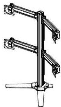
natural_image
Technical line drawing of a three-tier mechanical lift or support structure (no text or symbols)![VESA 100 x 100 75 x 75 COMPATIBLE INTERFACE TILT ADJUSTMENT +/-12° 0.31 [7.9] BASE THICKNESS 2.43 [61.6] COLUMN WIDTH 22.68 [576.0]](/content/2026/06/1183777/images/5cbeaa7397224d43a353aec500c6da81e32081f09ff01e05b9f8cdd035444d30.jpg)
![1.21 [30.6] 39.06 [992.2] 35.98 [913.8] MAX. MONITOR CENTER HEIGHT FROM SURFACE 2.27 [57.7] COLUMN DEPTH 3.19 [81.0] 15.50 [393.6]](/content/2026/06/1183777/images/f53e1b6723dff81c9df363af0de4d8fd5764ac796c3bb7b09c16b96c5207fa85.jpg)
K3G220
![34.02 [864.1] 1.60 [40.6] 15° MAX ANGLE 14.66 [372.4] MAX DISTANCE BETWEEN MONITOR:](/content/2026/06/1183777/images/3d28147588cbe32ee6bede15257d8fecd0d793fcdc27046f10af3a8185b179d0.jpg)

natural_image
Technical line drawing of a vertical mechanical structure with multiple arms and a base (no text or symbols)![VESA 100 X 100 75 X 75 COMPATIBLE INTERFACE TILT ADJUSTMENT +/-12° 0.25 [6.4] BASE THICKNESS 2.43 [61.6] COLUMN WIDTH 7.55 [191.8]](/content/2026/06/1183777/images/fc0f8dd5e1c684a07318ee3c4b37a8528f97ce20ef433bb7b6ad3524f9028623.jpg)
![1.21 [30.6] 38.81 [985.8] 36.04 [915.3] MAX. MONITOR CENTER HEIGHT FROM SURFACE 2.27 [57.7] COLUMN DEPTH 7.03 [178.5] 2.28 [57.9]](/content/2026/06/1183777/images/ee962973bf36640a23e6b029788d43cc3f58d9ac7eea91fbdfb3d075e7b11fa7.jpg)
LEGEND
| Tighten Fastener | |
| Apretar elemento de fijación | |
| Befestigungsteil festziehen | |
| Apertar fixador | |
| Serrare il fissaggio | |
| Bevestiging vastdraaien | |
| Serrez les fixations | |
| Loosen Fastener | |
| Aflojar elemento de fijación | |
| Befestigungsteil lösen | |
| Desapertar fixador | |
| Allentare il fissaggio | |
| Bevestiging losdraaien | |
| Desserrez les fixations | |
| Phillips Screwdriver | |
| Destornillador Phillips | |
| Kreuzschlitzschraubendreher | |
| Chave de fendas Phillips | |
| Cacciavite a stella | |
| Kruiskopschroevendraaier | |
| Tournevis à pointe cruciforme | |
| Open-Ended Wrench | |
| Llave de boca | |
| Gabelschlüssel | |
| Chave de bocas | |
| Chiave a punte aperte | |
| Steeksleutel | |
| Clé à fourche | |
| By Hand | |
| A mano | |
| Von Hand | |
| Com a mão | |
| A mano | |
| Met de hand | |
| À la main | |
| Hex-Head Wrench | |
| Llave de cabeza hexagonal | |
| Sechskantschlüssel | |
| Chave de cabeça sextavada | |
| Chiave esagonale | |
| Zeskantsleutel | |
| Clé à tête hexagonale |


Pencil Mark
| Marcar con lápiz |
| Stiftmarkierung |
| Marcar com lápis |
| Segno a matita |
| Potloodmerkteke |
| Marquage au cra |
Drill Hole
| Perforar |
| Bohrloch |
| Fazer furo |
| Praticare un foro |
| Gat boren |
| Percez un trou |
Adjust
| Ajustar |
| Einstellen |
| Ajustar |
| Regolare |
| Afstellen |
| Ajuster |
Remove
PARTS
![A (1) [array assembly] (K3G310 shown) C (1) [table top base] (K3F models only) B (see table) [cable management cover] K3F120 2 8 K3G120 2 8 K3F220 6 16 K3G220 6 16 K3G310 3 12 B (see table) [cable management cover] D (1) [column cap] E (1) [base cover] F (4) 1/4-20 x 1 1/4 G (6) [bumper] (K3F models only) H (see table) M4x30mm J (see table) M4x20mm K (see table) M4x12mm L (see table) 3/8" M (see table) 3/4" N (1) [grommet screw and base] (K3G models only) P (1) [grommet plate] (K3G models only) Q (1) 5/16" R (1) 3/16" S (1) 5/32"](/content/2026/06/1183777/images/6a26da121a4ea3dcfef48f895c4c4b1bda5066eec6dc492f2b05c6aa6a8450b2.jpg)
Assembly And Installation
K3F Mounts (Free-standing)
- Use four 1/4-20 x 1 1/4" flat head cap screws (F) to secure table top base (C) to array assembly (A). (See Figure 1)
NOTE: Make sure front of base (long legs) is on the display side when attaching base to array. (See Figure 1)

Figure 1
- Carefully manipulate base cover (E) to create an opening large enough to wrap cover around array column. (See Figure 2)
- Wrap base cover around column and slide it down until base cover fits securely onto table top base (C). (See Figure 2)

Figure 2
- Snap column cap (D) onto top of array assembly (A). (See Figure 3)

Figure 3
- Apply bumpers (G) to underside of table top base (C). (See Figure 4)

Figure 4
K3G Mounts (Grommet)
- Use four 1/4-20 x 1 1/4" flat head cap screws (F) to secure grommet plate (P) to array assembly (A). Make sure longer legs of grommet plate are aligned with the front of column. (See Figure 5)
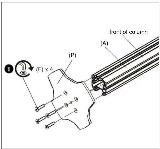
Figure 5
- Apply bumpers (G) to underside of grommet plate (P). (See Figure 6)

Figure 6
- Locate a flat surface (thickness minimum of 1" to maximum of 5") on which to mount the array assembly.
- If a hole doesn't already exist, drill a hole in desk with a diameter between 1/2" and 3 1/2" at desired mounting location. (See Figure 7)
-
Position mount on desk so that center hole of grommet plate (P) is centered over grommet hole. (See Figure 7)
-
Insert grommet screw (N) through grommet hole and thread into center hole of grommet plate (P). (See Figure 7)
- Tighten grommet screw (N) until grommet base is tightened against underside of desk and mount is securely mounted to desk. (See Figure 7)

Figure 7
- Carefully manipulate base cover (E) to create an opening large enough to wrap cover around array column. (See Figure 8)
- Wrap base cover around column and slide it down until base cover fits securely onto table top base (C). (See Figure 8)

Figure 8
- Snap column cap (D) onto top of array assembly (A). (See Figure 9)

Figure 9
Display Installation

WARNING: Exceeding the weight capacity can result in serious personal injury or damage to equipment! It is the installer's responsibility to make sure the combined weight of all components located on the K3 Series mount up to (and including) the display does not exceed 15 lbs (6.8 kg) per display for the K3F220, K3G220 and K3G310 mounts or 25 lbs (11.34 kg) per display for the K3F120 and K3G120 mounts.

CAUTION: Using screws of improper size may damage your display! Proper screws will easily thread into display mounting holes.
NOTE: Supplied screws (H, J and K) may not fit properly for all displays. See display's operating instructions for details.
IMPORTANT ! : When applicable, always install center display FIRST in order to prevent stand from tipping! If there are no center faceplates (K3F220 and K3G220), be sure to support opposite arm when mounting displays to prevent stand from tipping! If possible, mount displays to both sides simultaneously.
NOTE: Set height of lower center display prior to installing other displays. See Height Adjustment Section for details. Center of display must be at least 18" above desk surface.
Flush Mounting Holes
-
Position faceplate in desired mounting position. Adjust as required before proceeding. See Height Adjustment Section for details.
-
Using Phillips screwdriver, carefully install two M4 x 12mm Phillips pan machine screws (K) into the upper mounting holes on the display. Thread screws completely into display, then back out 3 complete turns. (See Figure 10)

Figure 10
-
Pick up and align display so that screws (K) (installed on the back of the display in the previous step) fit into the mounting holes on the faceplate. Lower the display firmly into place. (See Figure 10)
-
Using Phillips screwdriver, install two M4x12 mm Phillips pan machine screws (K) through the lower mounting holes on faceplate into the display. (See Figure 11)
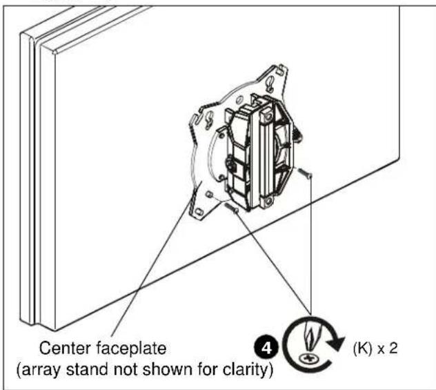
Figure 11
- Tighten all four screws (K). Do not overtighten!
NOTE: If roll adjustment is desired for center faceplate, do not tighten screws.
-
Repeat Steps 1-5 for other displays.
-
Proceed to Cable Management Section.
Recessed Mounting Holes
NOTE: If faceplate does not fit into recessed area of display, proceed with the steps in this section.
-
Determine depth of recessed mounting holes relative to back surface of display (against which faceplate will contact).
-
Select proper length spacer and screw from table below:
NOTE: All spacers used should be the same length. If the recess depths result in multiple spacer lengths, then select the longer spacer.
| IF recess DEPTH is: THEN use spacer: AND screw: | ||
| 3/8" or less L (3/8" long) | J (M4 x 20mm) | |
| More than 3/8" up to and including 3/4" | M (3/4" long) H (M4 x | 30mm) |

CAUTION: Using screws of improper size may damage your display! Proper screws will easily and completely thread into display mounting holes.
-
Using Phillips screwdriver, carefully install two selected screws (J or H) through selected spacers (L or M) into the upper mounting holes on the display. Thread screws completely into display, then back out 3 complete turns. (See Figure 12)
-
Pick up and align display so that screws (K) (installed on the back of the display in the previous step) fit into the mounting holes on the faceplate. Lower the display firmly into place. (See Figure 12)

Figure 12
-
Slide two remaining selected spacers (L or M) in between faceplate and display, positioning them over the lower two mounting holes. (See Figure 13)
-
Install two remaining selected screws (J or H) through lower two mounting holes on faceplate, selected spacers (L or M) into the lower mounting holes on the display. (See Figure 13)

Figure 13
- Tighten all four screws. Do not overtighten!
Adjustments
Pivot Adjustment
- Array arms may pivot toward the front of mount up to 15^ per arm. (See Figure 14)

WARNING: Pivoting array arms toward the back of mount may cause K3 Series mount to tip over causing serious personal injury or damage to equipment! Do not pivot arms toward back of mount! (See Figure 14)

Figure 14
- When arms are at desired pivot position, lock pivot position by tightening pivot adjustment screws using 5/16" hex key (N). (See Figure 15)

Figure 15
Height Adjustment
NOTE: Height adjustment for center displays should be set prior to installing display. Due to the location of the height adjustment screws for the center displays, the center displays will need to be removed in order to adjust the height. (See Figure 16)
- Loosen height adjustment screws for specific display that will be adjusted. (See Figure 16)
- Adjust arm or display to desired height. (See Figure 16)
- Tighten height adjustment screws to lock display's position. (See Figure 16)

Figure 16
Arm Extension (K3G310 only)
NOTE: For smaller displays or if converting to a 2x1 array, faceplate assemblies may be removed and reattached to fixed part of the arm. See Faceplate Assembly Section - Outside Faceplates for details.
- Turn arm extension adjustment knob counter-clockwise on arm to be adjusted. (See Figure 17)
- Adjust arm extension as desired. (See Figure 17)
- Turn arm extension adjustment knob clockwise on adjusted arm to lock position. (See Figure 17)
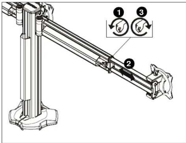
Figure 17
Faceplate Assembly Removal
Center Faceplate(s)
- Remove column cap (D) from array column. (See Figure 18)
- Loosen height adjustment screws for center faceplate assembly. (See Figure 18)
- Slide faceplate assembly up through column channel until it is removed from column. (See Figure 18)
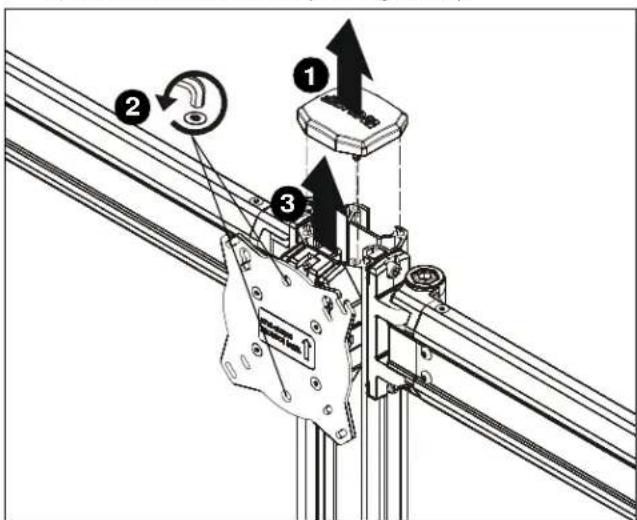
Figure 18
Outside Faceplates (K3G310 only)
- Remove hex head bolt from bottom of faceplate assembly. (See Figure 19)
- Slide out removable plate from bottom of faceplate assembly. (See Figure 19)
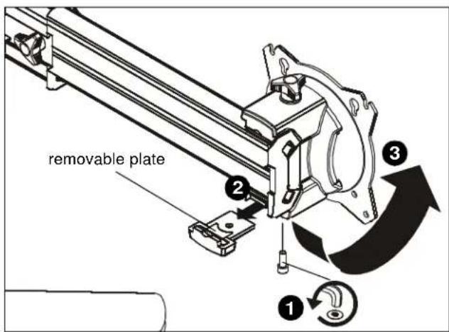
Figure 19
- Remove faceplate assembly from array arm. (See Figure 19)
To Reattach Outside Faceplate Assembly (K3G310 only)
NOTE: Faceplate assemblies may be reattached on the fixed part of the arm. (See Figure 20)
- Place faceplate assembly on array arm at desired mounting position. (See Figure 20)
- Slide removable plate back into slot at bottom of faceplate assembly. (See Figure 20)
- Reinstall hex head bolt removed in Step 1 to secure faceplate assembly to array arm. (See Figure 20)
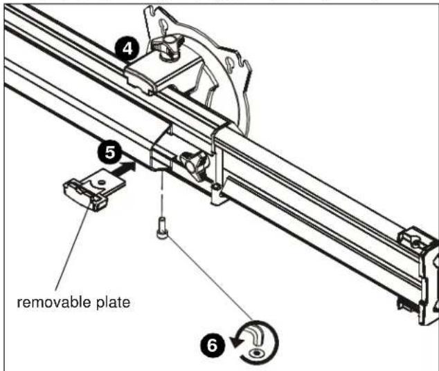
Figure 20
Lateral Shift (On Fixed Arm)
NOTE: The procedure below applies when the outside faceplates have been attached to the fixed arm. If outside faceplates are still attached to extension arms, use the extension arms for lateral shift.
- Loosen knob on top of outside faceplate assembly until faceplate can slide freely along array arm. (See Figure 21)
- Adjust lateral position as desired. (See Figure 21)
- Tighten knob to secure lateral position. (See Figure 21)

Figure 21
Pitch/Roll/Yaw Adjustment
Outside Faceplates
- Loosen knob on top of faceplate assembly. (See Figure 22)
- Adjust pitch, roll and/or yaw as desired. (See Figure 22)
- Tighten knob to secure desired faceplate position. (See Figure 22)

Figure 22
Center Faceplate(s)
Pitch
- Loosen knob on side of center faceplate assembly. (See Figure 23)
- Adjust pitch as desired. (See Figure 23)
- Tighten knob to secure desired pitch position. (See Figure 23)

Figure 23
Roll
- Loosen screws holding display to faceplate slightly.
- Adjust roll position as the mounting holes on faceplate allow.
- Tighten screws to lock roll position.
Cable Management
- Route cables from display through cable management covers (B) as desired. (See Figure 24) and (See Figure 25)
- Install cable management covers (B) onto array (A). (See Figure 24) and (See Figure 25)
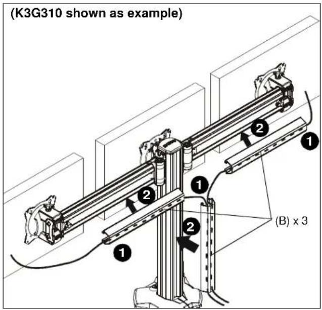
Figure 24
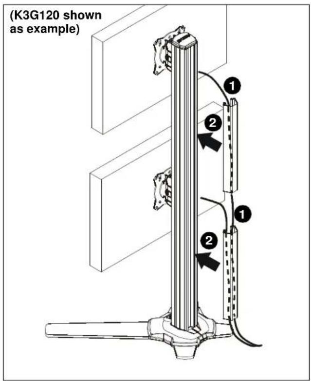
Figure 25

- INSTALLATION INSTRUCTIONS
- DISCLAIMER
- IMPORTANT SAFETY INSTRUCTIONS
- DIMENSIONS (CONTINUED)
- Assembly And Installation
- K3F Mounts (Free-standing)
- K3G Mounts (Grommet)
- Display Installation
- Flush Mounting Holes
- Recessed Mounting Holes
- Adjustments
- Pivot Adjustment
- Height Adjustment
- Arm Extension (K3G310 only)
- Faceplate Assembly Removal
- Center Faceplate(s)
- Outside Faceplates (K3G310 only)
- To Reattach Outside Faceplate Assembly (K3G310 only)
- Lateral Shift (On Fixed Arm)
- Pitch/Roll/Yaw Adjustment
- Outside Faceplates
- Pitch
- Roll
- Cable Management
Brand : Chief
Model : K3F120B
Category : Ceiling mount