
LFF225 - Outboard motor YAMAHA - Free user manual and instructions
Find the device manual for free LFF225 YAMAHA in PDF.

| Product Type | Outboard Motor |
| Brand | Yamaha |
| Model | LFF225 |
| Engine Type | 4-stroke DOHC V6 24-valve |
| Displacement | 4169 cm³ (254.4 c.i.) |
| Rated Power | 165.5 kW (225 HP) |
| Full Throttle Operating Range | 5000–6000 r/min |
| Steering System | Remote steering |
| Starting System | Electric starter |
| Trim and Tilt System | Power trim and tilt |
| Gear Shift Positions | Forward - Neutral - Reverse |
| Gear Ratio | 1.75 (21/12) |
| Recommended Fuel | Regular unleaded gasoline (min. 87 PON) |
| Recommended Engine Oil | YAMALUBE 4M FC-W or 4-stroke outboard oil, SAE 10W-30/10W-40/5W-30 |
| Engine Oil Capacity (without filter) | 6.0 L (6.34 US qt) |
| Engine Oil Capacity (with filter) | 6.3 L (6.66 US qt) |
| Recommended Gear Oil | Yamalube Marine Gearcase Lube or Hypoid gear oil SAE 80W/90 |
| Gear Oil Capacity | 1.040 L |
| Ignition System | TCI |
| Spark Plug | NGK LFR6A-11 (gap 1.0–1.1 mm) |
| Battery Requirements | Min. CCA 680 A, Min. RC 160 min |
| Weight (SUS X) | 260 kg (573 lb) |
| Overall Length | 958 mm (37.7 in) |
| Overall Width | 634 mm (25.0 in) |
| Overall Height (X) | 1890 mm (74.4 in) |
| Transom Height (X) | 643 mm (25.3 in) |
| Lubrication System | Wet sump |
| Maximum Generator Output | 70 A |
| Alert System | Overheat, Low oil pressure, Water separator, Low battery voltage, Engine trouble |
| Digital Electronic Control | Yes (with active indicator and alert indicator) |
Frequently Asked Questions - LFF225 YAMAHA
User questions about LFF225 YAMAHA
0 question about this device. Answer the ones you know or ask your own.
Ask a new question about this device
Download the instructions for your Outboard motor in PDF format for free! Find your manual LFF225 - YAMAHA and take your electronic device back in hand. On this page are published all the documents necessary for the use of your device. LFF225 by YAMAHA.
USER MANUAL LFF225 YAMAHA
Read this manual carefully before operating this onboard motor.
F225
LF225
F250
LF250
F300
LF300
F250D1
FL250D1
F300B1
FL300B1
LIT-18626-09-96
6CE-28199-34-E0
WARNING
The engine exhaust from this product contains chemicals known to the State of California to cause cancer, birth defects or other reproductive harm.
YAMAHA
LIT-CALIF-65-01
Read this manual carefully before operating this outboard motor. Keep this manual onboard in a waterproof bag when boating. This manual should stay with the outboard motor if it is sold.
EMU44140
To the owner
Thank you for selecting a Yamaha outboard motor. This Owner's Manual contains information needed for proper operation, maintenance and care. A thorough understanding of these simple instructions will help you obtain maximum enjoyment from your new Yamaha. If you have any question about the operation or maintenance of your outboard motor, please consult a Yamaha dealer.
In this Owner's Manual particularly important information is distinguished in the following ways.
⚠️: This is the safety alert symbol. It is used to alert you to potential personal injury hazards. Obey all safety messages that follow this symbol to avoid possible injury or death.
EWM00781
WARNING
A WARNING indicates a hazardous situation which, if not avoided, could result in death or serious injury.
ECM00701
NOTICE
A NOTICE indicates special precautions that must be taken to avoid damage to the outboard motor or other property.
TIP:
A TIP provides key information to make procedures easier or clearer.
Yamaha continually seeks advancements in product design and quality. Therefore, while this manual contains the most current product information available at the time of printing, there may be minor discrepancies between your machine and this manual. If
there is any question concerning this manual, please consult your Yamaha dealer.
To ensure long product life, Yamaha recommends that you use the product and perform the specified periodic inspections and maintenance by correctly following the instructions in the owner's manual. Any damage resulting from neglect of these instructions is not covered by warranty.
Some countries have laws or regulations restricting users from taking the product out of the country where it was purchased, and it may be impossible to register the product in the destination country. Additionally, the warranty may not apply in certain regions. When planning to take the product to another country, consult the dealer where the product was purchased for further information.
If you purchased this outboard motor used, see your Yamaha dealer to have it registered in your name in Yamaha records.
TIP:
The F225CA, LF225CA, F250CA, LF250CA, F300CA, LF300CA, F250DET1, FL250DET1, F300BET1, FL300BET1 and the standard accessories are used as a base for the explanations and illustrations in this manual. Therefore some items may not apply to every model.
EMU44150
F225, LF225, F250, LF250, F300, LF300,
F250D1, FL250D1, F300B1, FL300B1
OWNER'S MANUAL
©2012 by Yamaha Motor Co., Ltd.
1st Edition, November 2012
All rights reserved.
Any reprinting or unauthorized use
without the written permission of
Yamaha Motor Co., Ltd.
is expressly prohibited.
Printed in Japan
Safety information.... 1
Outboard motor safety ....1
Propeller.... 1
Rotating parts.... 1
Hot parts 1
Electric shock.... 1
Power trim and tilt 1
Engine shut-off cord (lanyard)...... 1
Gasoline.... 2
Gasoline exposure and spills ...... 2
Carbon monoxide.... 2
Modifications 2
Boating safety 2
Alcohol and drugs 2
Personal flotation devices (PFDs)..... 2
People in the water 2
Passengers 2
Overloading.... 2
Avoid collisions 3
Weather 3
Accident reporting 3
Boat education and training .... 3
Passenger training 4
Boating safety publications .... 4
Laws and regulations 4
Boating organizations......4
Basic boating rules (Rules of the road).... 5
Steering and sailing rules and sound signals.... 5
Rules when encountering vessels .... 5
Other special situations.... 6
General information 9
Identification numbers record......9
Outboard motor serial number ...... 9
Digital electronic control serial number....9
Key number.... 10
EC Declaration of Conformity (DoC).... 10
CE Marking ....10
Read manuals and labels...... 11
Warning labels 11
Specifications and requirements .... 14
Specifications.... 14
Installation requirements...... 16
Boat horsepower rating 16
Mounting outboard motor 16
Digital electronic control requirements.... 16
Battery requirements.... 17
Specifications of Battery...... 17
Mounting battery 17
Multiple batteries 17
Propeller selection 17
Counter rotation models.... 18
Start-in-gear protection 18
Engine oil requirements 18
Fuel requirements.... 19
Gasoline 19
Gasoline Additives 20
Anti-fouling paint 21
Outboard motor disposal requirements21
Emergency equipment...... 21
Emission control information ..... 21
North American models.... 21
Star labels 22
Components 24
Components diagram.... 24
Digital Electronic Control box ...... 27
Digital electronic control-active indicator 28
Digital electronic control-alert indicator 28
Control lever.... 29
Free throttle switch.... 29
Throttle friction adjuster.... 30
Engine shut-off cord (lanyard) and clip.... 30
Main switch 31
Start/Stop switch panel 31
All Start/Stop switch panel 32
Power trim and tilt switch on digital electronic control 32
Power trim and tilt switch on bottom cowling 32
Power trim and tilt switches (twin type) 33
Trim tab with anode 33
Tilt support lever for power trim and tilt model 34
Cowling lock lever 34
Flushing device 34
Fuel filter 35
Instruments and indicators ...... 36
Command Link Plus Display ...... 36
Engine warm-up indicator 36
Engine synchronization indicator .... 36
Overheat alert 36
Low oil pressure-alert.... 37
Water separator alert 37
Low battery voltage-alert...... 38
Engine trouble alert.... 38
Command Link Multifunction Meters 39
Command Link Multifunction Tachometer ....39
Low oil pressure-alert...... 40
Overheat alert 40
Water separator alert 41
Engine trouble alert.... 41
Low battery voltage-alert...... 42
Command Link Multifunction Speed & Fuel Meter 42
Command Link Multifunction Speedometer43
Command Link Multifunction Fuel Management Meter ....44
Optional meters.... 44
Engine control system...... 46
Alert system ....46
Digital Electronic Control alert...... 46
Overheat alert 46
Low oil pressure alert.... 47
Water separator alert 48
Installation 50
Installation 50
Mounting the outboard motor...... 50
Operation 52
First-time operation 52
Filling engine oil 52
Breaking in engine 52
Getting to know your boat 52
Checks before starting engine ..... 52
Fuel level.... 53
Removing top cowling 53
Fuel system.... 53
Controls.... 54
Engine shut-off cord (lanyard)...... 54
Engine oil 54
Outboard motor 55
Flushing device 55
Installing top cowling 55
Checking power trim and tilt system.... 57
Battery.... 57
Filling fuel 58
Operating engine 58
Sending fuel 58
Starting engine 58
Checks after starting engine ...... 60
Cooling water 60
Warming up engine.... 61
Electric start models.... 61
Checks after engine warm up ...... 61
Shifting 61
Stop switches 61
Shifting.... 61
Stopping boat.... 62
Trolling 62
Adjusting trolling speed 62
Stopping engine.... 63
Procedure for stopping engine ...... 63
Trimming outboard motor...... 64
Adjusting trim angle (Power trim and tilt) 64
Adjusting boat trim 65
Tilting up and down...... 66
Procedure for tilting up (power trim and tilt models).... 66
Procedure for tilting down (power trim and tilt models).... 67
Shallow water 68
Cruising in shallow water 68
Operating in other conditions...... 69
Maintenance.... 70
Transporting and storing outboard motor.... 70
Storing outboard motor 70
Conditioning and stabilizing gasoline 70
Procedure 71
Lubrication 71
Cleaning and anticorrosion measures 71
Flushing cooling water passage..... 71
Checking painted surface of outboard motor 72
Periodic maintenance.... 72
Replacement parts.... 73
Maintenance interval guidelines..... 73
Maintenance chart 1 74
Maintenance chart 2 76
Greasing 77
Inspecting spark plug 77
Inspecting engine idle speed ..... 79
Changing engine oil 79
Inspecting wiring and connectors.... 85
Inspecting propeller.... 85
Removing propeller.... 86
Installing propeller.... 87
Changing gear oil.... 88
Inspecting and replacing anode(s)....89
Checking battery (for electric start models) 90
Connecting the battery.... 91
Disconnecting the battery 92
Trouble Recovery....93
Troubleshooting 93
Temporary action in emergency..... 96 Impact damage ..... 96
Running single engine (twin engines) 96
Replacing fuse 96
Power trim and tilt unit will not operate....97
Water separator-alert indicator blinks while cruising .... 98
Treatment of submerged motor..... 99
Consumer information ...... 100
YAMAHA FOUR-STROKE OUTBOARD MOTOR THREE-YEAR LIMITED WARRANTY 100
IMPORTANT WARRANTY INFORMATION IF YOU USE YOUR YAMAHA OUTSIDE THE U.S.A. OR CANADA...... 102
EMU33622
Outboard motor safety
Observe these precautions at all times.
EMU36501
Propeller
People can be injured or killed if they come in contact with the propeller. The propeller can keep moving even when the motor is in neutral, and sharp edges of the propeller can cut even when stationary.
- Stop the engine when a person is in the water near you.
- Keep people out of reach of the propeller, even when the engine is off.
EMU40271
Rotating parts
Hands, feet, hair, jewelry, clothing, personal flotation device (PFD) straps, etc., can become entangled with internal rotating parts of the engine, resulting in serious injury or death.
Keep the top cowling in place whenever possible. Do not remove or replace the top cowling with the engine running.
Only operate the engine with the top cowling removed according to the specific instructions in the manual. Keep hands, feet, hair, jewelry, clothing, PFD straps, etc., away from any exposed moving parts.
EMU33640
Hot parts
During and after operation, engine parts are hot enough to cause burns. Avoid touching any parts under the top cowling until the engine has cooled.
EMU33650
Electric shock
Do not touch any electrical parts while starting or operating the engine. They can cause shock or electrocution.
EMU33660
Power trim and tilt
Body parts can be crushed between the motor and the clamp bracket when the motor is trimmed or tilted. Keep body parts out of this area at all times. Be sure no one is in this area before operating the power trim and tilt mechanism.
The power trim and tilt switches operate even when the main switch is off. Keep people be away from the switches whenever working around the motor.
Never get under the lower unit while it is tilted, even when the tilt support lever is locked.
Severe injury could occur if the outboard motor accidentally falls.
EMU41251
Engine shut-off cord (lanyard)
Attach the engine shut-off cord so that the engine stops if the operator falls overboard or leaves the helm. This prevents the boat from running away under power and leaving people stranded, or running over people or objects.
Always attach the engine shut-off cord to a secure place on your clothing or your arm or leg while operating. Do not remove it to leave the helm while the boat is moving. Do not attach the engine shut-off cord to clothing that could tear loose, or route the engine shut-off cord where it could become entangled, preventing it from functioning.
Do not route the engine shut-off cord where it is likely to be accidentally pulled out. If the engine shut-off cord is pulled during operation, the engine will shut off and you will lose most steering control. The boat could slow rapidly, throwing people and objects forward.
EMU33810
Gasoline
Gasoline and its vapors are highly flammable and explosive. Always, refuel according to the procedure on page 58 to reduce the risk of fire and explosion.
EMU33820
Gasoline exposure and spills
Take care not to spill gasoline. If gasoline spills, wipe it up immediately with dry rags. Dispose of rags properly.
If any gasoline spills onto your skin, immediately wash with soap and water. Change clothing if gasoline spills on it.
If you swallow gasoline, inhale a lot of gasoline vapor, or get gasoline in your eyes, get immediate medical attention. Never siphon fuel by mouth.
EMU33900
Carbon monoxide
This product emits exhaust gases which contain carbon monoxide, a colorless, odorless gas which may cause brain damage or death when inhaled. Symptoms include nausea, dizziness, and drowsiness. Keep cockpit and cabin areas well ventilated. Avoid blocking exhaust outlets.
EMU33780
Modifications
Do not attempt to modify this outboard motor. Modifications to your outboard motor may reduce safety and reliability, and render the outboard unsafe or illegal to use.
EMU33740
Boating safety
This section includes a few of the many important safety precautions that you should follow when boating.
EMU33710
Alcohol and drugs
Never operate after drinking alcohol or taking drugs. Intoxication is one of the most common factors contributing to boating fatalities.
EMU40280
Personal flotation devices (PFDs)
Have an approved PFD on board for every occupant. Yamaha recommends that you must wear a PFD whenever boating. At a minimum, children and non-swimmers should always wear PFDs, and everyone should wear PFDs when there are potentially hazardous boating conditions.
EMU33731
People in the water
Always watch carefully for people in the water, such as swimmers, skiers, or divers, whenever the engine is running. When someone is in the water near the boat, shift into neutral and stop the engine.
Stay away from swimming areas. Swimmers can be hard to see.
The propeller can keep moving even when the motor is in neutral. Stop the engine when a person is in the water near you.
EMU33751
Passengers
Consult your boat manufacturer's instructions for details about appropriate passenger locations in your boat and be sure all passengers are positioned properly before accelerating and when operating above an idle speed. Standing or sitting in non-designated locations may result in being thrown either overboard or within the boat due to waves, wakes, or sudden changes in speed or direction. Even when people are positioned properly, alert your passengers if you must make any unusual maneuver. Always avoid jumping waves or wakes.
EMU33760
Overloading
Do not overload the boat. Consult the boat capacity plate or boat manufacturer for maximum weight and number of passengers. Be
sure that weight is properly distributed according to the boat manufacturers instructions. Overloading or incorrect weight distribution can compromise the boats handling and lead to an accident, capsizing or swamping.
EMU33772
Avoid collisions
Scan constantly for people, objects, and other boats. Be alert for conditions that limit your visibility or block your vision of others.

natural_image
Illustration of a person's head with two heads, one moving toward a boat and the other swimming in water (no text or symbols)ZMU06025
Operate defensively at safe speeds and keep a safe distance away from people, objects, and other boats.
- Do not follow directly behind other boats or waterskiers.
- Avoid sharp turns or other maneuvers that make it hard for others to avoid you or understand where you are going.
- Avoid areas with submerged objects or shallow water.
- Ride within your limits and avoid aggressive maneuvers to reduce the risk of loss of control, ejection, and collision.
- Take early action to avoid collisions. Remember, boats do not have brakes, and stopping the engine or reducing throttle can reduce the ability to steer. If you are not sure that you can stop in time before hitting an obstacle, apply throttle and turn in another direction.
EMU33790
Weather
Stay informed about the weather. Check weather forecasts before boating. Avoid boating in hazardous weather.
EMU44160
Accident reporting
Boat operators are required by law to file a Boating Accident Report with their boating law enforcement agency if their boat is involved in any of the following accidents:
- There is loss of life or probable loss of life.
- There is personal injury that requires medical attention beyond first aid.
- There is property damage to boats or other property over a certain amount.
- There is complete loss of a boat.
Contact local law enforcement personnel if a report is necessary.
EMU44170
Boat education and training
For U.S.A.
Operators should take a boating safety course. This may be required in your state. Many of the organizations listed in the next section can provide information about courses in your area.
You may also want to consider an Internet-based program for basic boater education. The Online Boating Safety Course provided by the BoatU.S. Foundation, is approved by the National Association of State Boating Law Administrators (NASBLA) and recognized by the United States Coast Guard. Most, but not all, states accept this course to meet their minimum requirements. While it cannot replace an in-depth course such as one offered by the U.S. Coast Guard, U.S. Power Squadron, or other organization, this online course does provide a general overview of the basics in boating safety, require-
ments, navigation, and operation. Upon successful completion of the course, the user can download a certificate of completion immediately or, for a small charge, request one by mail. To take this free course, go to boatus.org.
For Canada
All operators of pleasure craft must illustrate competency by means of a Pleasure Craft Operators Card with the exception of Personal Water Craft used for rental purposes which require a rental checklist be completed. Pleasure Craft Operators Cards can be obtained following the completion of a competency course, with an on-line option. Details can be found on Transport Canada's website. www.tc.gc.ca
EMU33880
Passenger training
Make sure at least one other passenger is trained to operate the boat in the event of an emergency.
EMU33890
Boating safety publications
Be informed about boating safety. Additional publications and information can be obtained from many boating organizations.
EMU33590
Laws and regulations
Know the marine laws and regulations where you will be boating- and obey them. Several sets of rules prevail according to geographic location, but all are basically the same as the International Rules of the Road. The rules presented in the following section are condensed- and have been provided for your convenience only.
Contact the U.S. Coast Guard, the National Association of State Boating Law Administrators, or your local Power Squadron for a complete set of rules governing the waters in which you will be using your boat.
EMU44180
Boating organizations
The following organizations provide boating safety training and information about boating safety and laws.
In the U.S.A.
United States Coast Guard
Consumer Affairs Staff (G-BC)
Office of Boating, Public, and Consumer Affairs
U.S. Coast Guard Headquarters
Washington, D.C. 20593-0001
http://www.uscgboating.org/
United States Power Squadrons
1-888-FOR-USPS (1-888-367-8777)
http://www.usps.org/
Boat Owners Association of The United States
1-800-336-BOAT (1-800-336-2628)
http://www.boatus.com/
National Association of State Boating Law Administrators (NASBLA)
1500 Leestown Road, Suite 330
Lexington, KY 40511 859-225-9497
http://www.nasbla.org/
National Marine Manufacturers Association (NMMA)
200 East Randolph Drive
Suite 5100
Chicago, IL 60601
http://www.nmma.org/
Marine Retailers Association of America
155 N. Michigan Ave. Chicago,
IL 60304
http://www.mraa.com/
In the Canada
National Marine Manufacturers Association Canada
14 McEwan Drive
Suite 8
Bolton, ON
L7E 1H1
http://www.nmma.org/
EMU33691
Basic boating rules (Rules of the road)
Just as there are rules that apply when you are driving on streets and highways, there are waterway rules that apply when you are driving your boat. These rules are used internationally. (For U.S.A.: and are also enforced by the United States Coast Guard and local agencies.) You should be aware of these rules, and follow them whenever you encounter another vessel on the water.
EMU33700
Steering and sailing rules and sound signals
Whenever two vessels on the water meet one another, one vessel has the right-of-way; it is called the “stand-on” vessel. The vessel that does not have the right-of-way is called the “give-way” or “burdened” vessel. These rules determine which vessel has the right-of-way, and what each vessel should do.
Stand-on vessel
The vessel with the right-of-way has the duty to continue its course and speed, except to avoid an immediate collision. When you maintain your direction and speed, the other vessel will be able to determine how best to avoid you.
Give-way vessel
The vessel that does not have the right-of-way has the duty to take positive and timely action to stay out of the way of the Stand-On vessel. Normally, you should not cross in front of the vessel with the right-of-way. You should slow down or change directions briefly and pass behind the other vessel. You should always move in such a way that the operator of the other vessel can see what you are doing.
"The general prudential rule"
This rule is called Rule 2 in the International Rules and says,
"In obeying and construing these rules due regard shall be had to all dangers of navigation and collision, and to any special circumstances, which may render a departure from the above rules necessary in order to avoid immediate danger."
In other words, follow the standard rules except when a collision will occur unless both vessels try to avoid each other. If that is the case, both vessels become “ Give-Way ” vessels.
EMU25521
Rules when encountering vessels
There are three main situations that you may encounter with other vessels which could lead to a collision unless the Steering Rules are followed:
Meeting: (you are approaching another vessel head-on)
Crossing: (you are traveling across the other vessel's path)
Overtaking: (you are passing or being passed by another vessel)
In the following illustration, your boat is in the center. You should give the right-of-way to any vessels shown in white area (you are the Give-Way vessel). Any vessels in the shaded area must yield to you (they are the Give-
Way vessels). Both you and the meeting vessel must alter course to avoid each other.
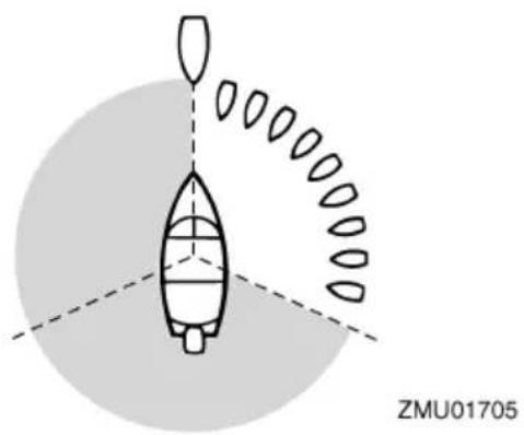
natural_image
Diagram of a boat with a circular base and a vertical structure, no text or symbols presentMeeting
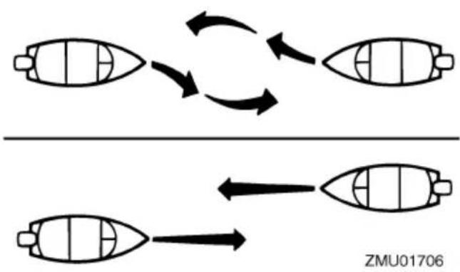
If you are meeting another power vessel head on, and are close enough to run the risk of collision, neither of you has the right-of-way. Both of you should alter course to avoid an accident. You should keep the other vessel on your port (left) side. This rule doesn't apply if both of you will clear one another if you continue on your set course and speed.
flowchart
graph TD
    A["Top Boat"] --> B["Bottom Boat"]
    B --> C["Top Boat"]
    style A fill:#f9f,stroke:#333
    style B fill:#bbf,stroke:#333
    style C fill:#dfd,stroke:#333
Crossing
When two power driven vessels are crossing each other's path close enough to run the risk of collision, the vessel which has the other on the starboard (right) side must keep out of the way of the other. If the other vessel is on your right, you must keep out of its way; you are the Give-Way vessel. If the other vessel is on your port (left) side, remember that you should maintain course and direction, provided the other vessel gives you the right-of-way as it should.
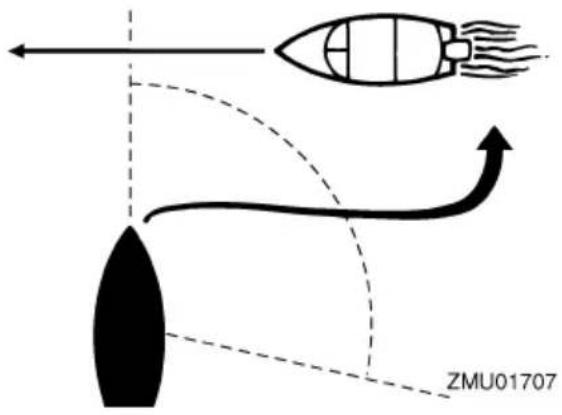
Overtaking
If you are passing another vessel, you are the "Give-Way" vessel. This means that the other vessel is expected to maintain its course and speed. You must stay out of its way until you are clear of it. Likewise, if another vessel is passing you, you should maintain your speed and direction so that the other vessel can steer itself around you.
EMU25531
Other special situations
There are three other rules you should be aware of when driving your boat around other vessels.
Narrow channels and bends
When navigating in narrow channels, you should keep to the right when it is safe and practical to do so. If the operator of a power-driven vessel is preparing to go around a bend that may obstruct the view of other water vessels, the operator should sound a prolonged blast on the whistle (4 to 6 seconds). If another vessel is around the bend, it too should sound the whistle. Even if no reply is heard, however, the vessel should still proceed around the bend with caution. If you navigate such waters with your boat, you will need to carry a portable air horn, available from local marine supply stores.
Fishing vessel right-of-way
All vessels that are fishing with nets, lines or trawls are considered to be “fishing vessels” under the International Rules. Vessels with trolling lines are not considered fishing vessels. Fishing vessels have the right-of-way regardless of position. Fishing vessels cannot, however, impede the passage of other vessels in narrow channels.
Sailing vessel right-of-way
Sailing vessels should normally be given the right-of-way. The exceptions to this are:
- When the sailing vessel is overtaking the power-driven vessel, the power-driven vessel has the right-of-way.
- Sailing vessels should keep clear of any fishing vessel.
- In a narrow channel, a sailing vessel should not hamper the safe passage of a power-driven vessel that can navigate only in such a channel.
Reading buoys and other markers
The waters of the United States are marked for safe navigation by the lateral system of buoyage. Simply put, buoys and markers have an arrangement of shapes, colors, numbers and lights to show which side of the buoy a boater should pass on when navigating in a particular direction. The markings on these buoys are oriented from the perspective of being entered from seaward (the boater is going towards the port). This means that red buoys are passed on the starboard (right) side when proceeding from open water into port, and black buoys are to port (left) side. When navigating out of port, your position with respect to the buoys should be reversed; red buoys should be to port and black buoys to starboard.
Many bodies of water used by boaters are entirely within the boundaries of a particular state. The Uniform State Waterway Marking System has been devised for these waters. This system uses buoys and signs with distinctive shapes and colors to show regulatory or advisory information. These markers are white with black letters and orange boarders. They signify speed zones, restricted areas, danger areas, and general information.
Remember, markings may vary by geographic location. Always consult local boating authorities before driving your boat in unfamiliar waters.
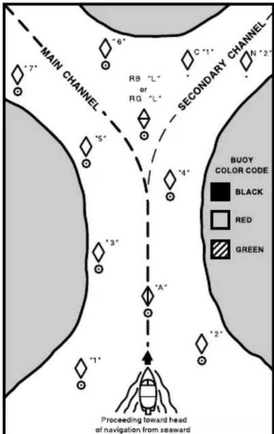
SECONDARY CHANNEL BUOYS STARTS NEW NUMBERING SYSTEM

CAN BUOY
Odd number. Leave to port.
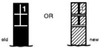

NUN BUOY
Even number. Leave to starboard
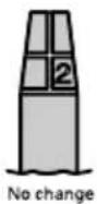
MAIN CHANNEL BUOYS

3' '5' '7'
LIGHTED BUOY (Perl Hand)
Odd number, increasing toward head of navigation. Leave to port (left) proceeding upstream.
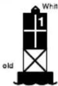
OR
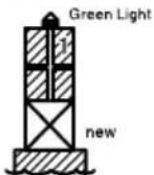

“4”“6”
LIGHTED BUOY (Starboard Hand)
Even number, increasing toward head of navigation. Leave to starboard (right) proceeding upstream.
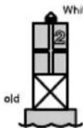
OR
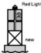

LIGHTED SAFE WATER BUOY
No number. Marks midchannel, pass on either side. Letter has no lateral significance, used for identification and location purposes.
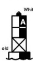
OR
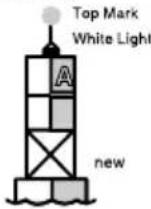

3 "L"
RG
L
LIGHTED PREFERRED CHANNEL TO PORT BUOY
No number. Topmost band red – preferred channel is to left of buoy. Letter has no lateral significance, used for identification and location purposes.
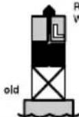
Red or White Light
ZMU01708
EMU25171
Identification numbers record
EMU25184
Outboard motor serial number
The outboard motor serial number is stamped on the label attached to the port side of the clamp bracket.
Record your outboard motor serial number in the spaces provided to assist you in ordering spare parts from your Yamaha dealer or for reference in case your outboard motor is stolen.
- Outboard motor serial number location

ZMU01692
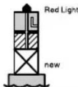
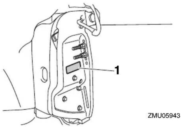
EMU34943
Digital electronic control serial number
The digital electronic control serial number is stamped on the label attached to the digital electronic control box.
Record your digital electronic control serial number in the spaces provided to assist you in newly connecting the digital electronic control to the outboard motor.
TIP:
Consult your Yamaha dealer if you have any questions concerning the digital electronic control serial number.
- Digital electronic control serial number location
ZMU05917
EMU41570
Key number
The key identification number is stamped on the spare key as shown in the illustration. Keep the spare key in a safe place and record this number in the space provided for reference in case that you need a new key.
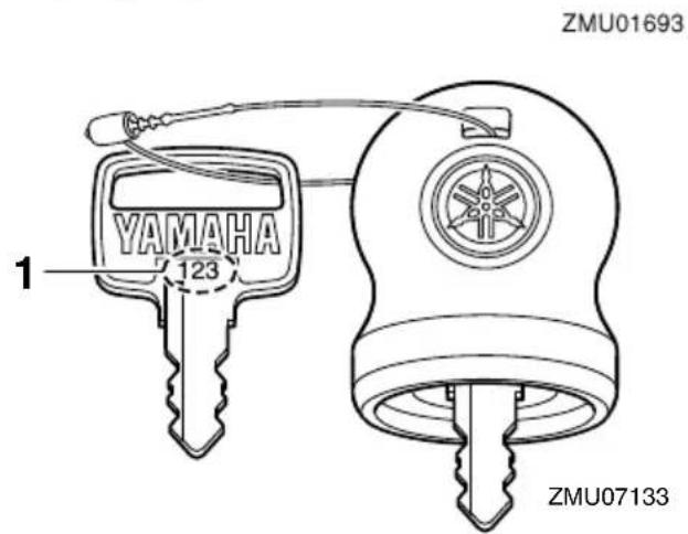
- Key number
EMU38980
EC Declaration of Conformity (DoC)
This declaration is included with outboard motors that conform to European regulations.
This outboard motor conforms to certain portions of the European Parliament directive relating to machinery.
Each conformed outboard motor accompanied with EC DoC.EC DoC contains the following information;
• Name of Engine Manufacture
- Model name
- Product code of model (Approved model code)
• Code of conformed directives
EMU38992
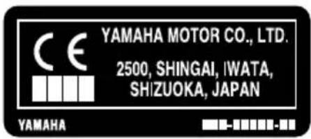
CE Marking
This label is affixed to outboard motors that conform to European regulations.
Outboard motors affixed with this “CE” marking conform with the directives of; 2006/42/EC, 94/25/EC - 2003/44/EC and 2004/108/EC.
- CE marking location
ZMU06040
EMU33523
Read manuals and labels
Before operating or working on this outboard motor:
- Read this manual.
- Read any manuals supplied with the boat.
- Read all labels on the outboard motor and the boat.
If you need any additional information, contact your Yamaha dealer.
EMU33832
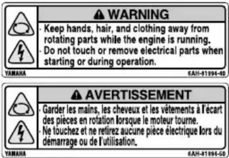
Warning labels
If these labels are damaged or missing, contact your Yamaha dealer for replacements. F225, LF225, F250, LF250, F300, LF300, F250D1, FL250D1, F300B1, FL300B1
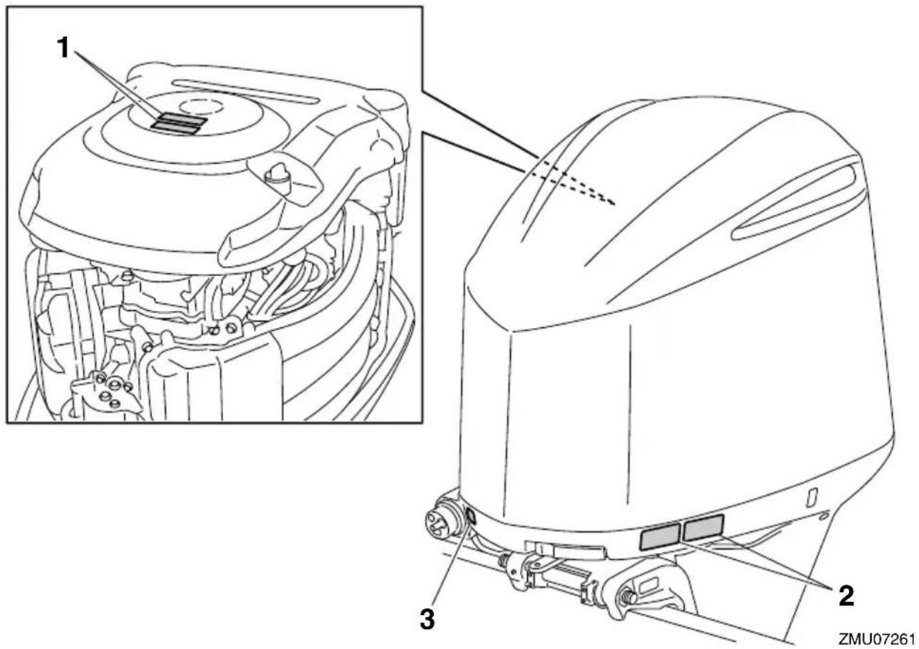
1
The above warning labels mean as follows.
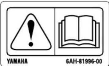
1
EWM01681

WARNING
- Keep hands, hair, and clothing away from rotating parts while the engine is running.
- Do not touch or remove electrical parts when starting or during operation.
2
EWM01671

WARNING
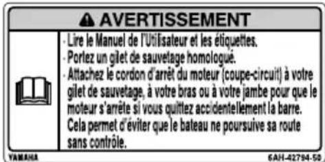
- Read Owner's Manuals and labels.
- Wear an approved personal flotation device (PFD).
- Attach engine shut-off cord (lanyard) to your PFD, arm, or leg so the engine stops if you accidentally leave the
ZMU06191
helm, which could prevent a runaway boat.
EMU33850
Other labels
3
ZMU05710
EMU35132
Symbols
The following symbols mean as follows.
Notice/Warning

ZMU05696
Read Owner's Manual

natural_image
Simple line drawing of an open book with no text or symbols visibleZMU05664
Hazard caused by continuous rotation
natural_image
Triangular warning symbol with two curved arrows indicating cycle (no text or numbers)ZMU05665
Electrical hazard
ZMU05666
EMU40500
Specifications
TIP:
“(SUS)” indicates that the specification is for the outboard motor when it is equipped with a stainless steel propeller.
EMU2821R
Dimension and weight:
Overall length:
958 mm (37.7 in)
Overall width:
634 mm (25.0 in)
Overall height X:
1890 mm (74.4 in)
Overall height U:
F250CA 2017 mm (79.4 in)
F250DET1 2017 mm (79.4 in)
F300BET1 2017 mm (79.4 in)
F300CA 2017 mm (79.4 in)
FL250DET1 2017 mm (79.4 in)
FL300BET1 2017 mm (79.4 in)
LF250CA 2017 mm (79.4 in)
LF300CA 2017 mm (79.4 in)
Motor transom height X:
643 mm (25.3 in)
Motor transom height U:
F250CA 770 mm (30.3 in)
F250DET1 770 mm (30.3 in)
F300BET1 770 mm (30.3 in)
F300CA 770 mm (30.3 in)
FL250DET1 770 mm (30.3 in)
FL300BET1 770 mm (30.3 in)
LF250CA 770 mm (30.3 in)
LF300CA 770 mm (30.3 in)
Dry weight (SUS) X:
260 kg (573 lb)
Dry weight (SUS) U:
F250CA 268 kg (591 lb)
F250DET1 268 kg (591 lb)
F300BET1 268 kg (591 lb)
F300CA 268 kg (591 lb)
FL250DET1 268 kg (591 lb)
FL300BET1 268 kg (591 lb)
LF250CA 268 kg (591 lb)
LF300CA 268 kg (591 lb)
Performance:
Full throttle operating range:
5000–6000 r/min
Rated power:
F225CA 165.5 kW (225 HP)
F250CA 183.8 kW (250 HP)
F250DET1 183.8 kW (250 HP)
F300BET1 220.6 kW (300 HP)
F300CA 220.6 kW (300 HP)
FL250DET1 183.8 kW (250 HP)
FL300BET1 220.6 kW (300 HP)
LF225CA 165.5 kW (225 HP)
LF250CA 183.8 kW (250 HP)
LF300CA 220.6 kW (300 HP)
Idle speed (in neutral):
650-750 r/min
Power unit:
Type:
4-stroke DOHC V6 24valves
Total displacement:
4169 cm ^3 (254.4 c.i.)
Bore × stroke:
96.0× 96.0mm (3.78× 3.78 in)
Ignition system:
TCI
Spark plug (NGK):
LFR6A-11
Spark plug gap:
1.0–1.1 mm (0.039–0.043 in)
Steering system:
Remote steering
Starting system:
Electric starter
Starting carburetion system:
Fuel injection
Specifications and requirements
Valve clearance IN (cold engine):
0.17–0.24 mm (0.0067–0.0094 in)
Valve clearance EX (cold engine):
0.31–0.38 mm (0.0122–0.0150 in)
Min. cold cranking amps (CCA/SAE):
680 A
Min. marine cranking amps (MCA/ABYC):
770 A
Min. reserve capacity (RC/SAE):
160 minutes
Maximum generator output:
70 A
Lower unit:
Gear shift positions:
Forward-neutral-reverse
Gear ratio:
1.75(21/12)
Trim and tilt system:
Power trim and tilt
Propeller mark:
F225CA M/T
F250CA M/T
F250DET1 M/T
F300BET1 M/T
F300CA M/T
FL250DET1 ML/TL
FL300BET1 ML/TL
LF225CA ML/TL
LF250CA ML/TL
LF300CA ML/TL
Fuel and oil:
Recommended fuel:
F225CA Regular unleaded gasoline
F250CA Regular unleaded gasoline
F250DET1 Regular unleaded gaso- line
F300BET1 Premium unleaded gaso- line
F300CA Premium unleaded gasoline
FL250DET1 Regular unleaded gaso- line
FL300BET1 Premium unleaded gasoline
LF225CA Regular unleaded gasoline
LF250CA Regular unleaded gasoline
LF300CA Premium unleaded gaso- line
Min. pump octane number (PON):
F225CA 87
F250CA 87
F250DET1 87
F300BET1 89
F300CA 89
FL250DET1 87
FL300BET1 89
LF225CA 87
LF250CA 87
LF300CA 89
Recommended engine oil:
YAMALUBE 4M FC-W or 4-stroke
outboard motor oil
Recommended engine oil grade 1:
SAE 10W-30/10W-40/5W-30
API SE/SF/SG/SH/SJ/SL
Engine oil quantity (without oil filter replacement):
6.0 L (6.34 US qt, 5.28 Imp.qt)
Engine oil quantity (with oil filter replacement):
6.3 L (6.66 US qt, 5.54 Imp.qt)
Lubrication system:
Wet sump
Recommended gear oil:
Yamalube Marine Gearcase Lube or
Hypoid gear oil
Recommended gear oil grade:
SAE 80W API GL-5 /
SAE 90 API GL-5
Gear oil quantity:
1.040 L (1.099 US qt, 0.915 Imp.qt)
Tightening torque:
Spark plug:
28 Nm (2.86 kgf-m, 20.7 ft-lb)
Propeller nut:
54 Nm (5.51 kgf-m, 39.8 ft-lb)
Engine oil drain bolt:
27 Nm (2.75 kgf-m, 19.9 ft-lb)
Engine oil filter:
18 Nm (1.84 kgf-m, 13.3 ft-lb)
EMU33554
Installation requirements
EMU40480
Boat horsepower rating
EWM01560

WARNING
Overpowering a boat can cause severe instability.
Before mounting the outboard motor, check that the horsepower of the outboard motor does not exceed the maximum horsepower rating on the capacity plate of the boat. If the boat does not have a capacity plate, consult the boat manufacturer.
EMU40490
Mounting outboard motor
EWM02500

WARNING
- Improper mounting of the outboard motor could result in hazardous conditions such as poor handling, loss of control, or fire hazards.
- Because the outboard motor is very heavy, special equipment and training is required to mount it safely.
Your dealer or other person experienced in proper rigging should mount the outboard motor using correct equipment and complete rigging instructions. For further information, see page 50.
EMU34952
Digital electronic control requirements
The digital electronic control be equipped with a start-in-gear protection device(s). This device prevents the engine from starting unless it is in neutral.
EWM01580

WARNING
- If the engine starts in gear, the boat can move suddenly and unexpectedly, possibly causing a collision or throwing passengers overboard.
- If the engine ever starts in gear, the start-in-gear protection device is not working correctly and you should discontinue using the outboard. Contact your Yamaha dealer.
This digital electronic control unit is only available for the outboard motor which you have purchased.
Prior to use of the digital electronic control unit, set it in order to operate your outboard motor only. Otherwise, it will not be possible to operate the outboard motor.
Perform setting of the outboard motor and the digital electronic control unit in the following cases.
- If a used outboard motor is installed
- If the digital electronic control unit is replaced
- If the ECM (Electronic control module) of the used outboard motor is replaced
- If the ECM (Electronic control module) of the digital electronic control unit is replaced
Consult your Yamaha dealer for setting.
EMU25694
Battery requirements
EMU25713
Specifications of Battery
Use a fully charged battery that meets the following specifications. The engine cannot be started if battery voltage is too low.
Minimum cold cranking amps
(CCA/SAE):
680 A
Minimum marine cranking amps
(MCA/ABYC):
770 A
Minimum reserve capacity (RC/SAE):
160 minutes
ECM01061
NOTICE
Do not use a battery that does not meet the specified capacity. If a battery that does not meet specifications is used, the electric system could perform poorly or be overloaded, causing electric system damage.
EMU36290
Mounting battery
Mount the battery holder securely in a dry, well-ventilated, vibration-free location in the boat. WARNING! Do not put flammable items, or loose heavy or metal objects in the same compartment as the battery. Fire, explosion or sparks could result.
[EWM01820]
EMU36300
Multiple batteries
To connect multiple batteries, such as for multiple engine configurations or for an accessory battery, consult your Yamaha dealer about battery selection and correct wiring.
EMU41600
Propeller selection
Next to selecting an outboard motor, selecting the right propeller is one of the most important purchasing decisions a boater can make. The type, size, and design of your propeller have a direct impact on acceleration, top speed, fuel economy, and even engine life. Yamaha designs and manufactures propellers for every Yamaha outboard motor and every application.
Your Yamaha dealer can help you select the right propeller for your boating needs. Select a propeller that will allow the engine to reach the middle or upper half of the operating range at full throttle with the maximum boat-load. Generally, select a larger pitch propeller for a smaller operating load and a smaller pitch propeller for a heavier load. If you carry loads that vary widely, select the propeller that lets the engine run in the proper range for your maximum load but remember that you may need to reduce your throttle setting to stay within the recommended engine speed range when carrying lighter loads.
Yamaha recommends to use a propeller suitable for the “Shift Dampener System (SDS)”. For further information, consult your Yamaha dealer.
To check the propeller, see page 85.
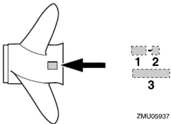
-
Propeller pitch in inches
-
Type of propeller (propeller mark)
- Propeller diameter in inches
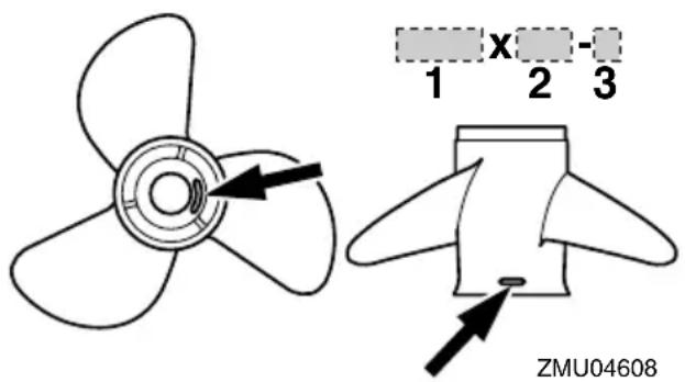
- Propeller diameter in inches
- Propeller pitch in inches
- Type of propeller (propeller mark)
EMU36310
Counter rotation models
Standard outboard motors rotate clockwise. Counter rotation models rotate counterclockwise. Counter rotation models are typically used in multiple motor setups and are marked with an "L" on the gear case above the anti-ventilation plate.
On counter rotation models, be sure to use a propeller intended for counterclockwise rotation. These propellers are identified with the letter "L" after the size indication on the propeller. WARNING! Never use a standard propeller with a counter rotation motor, or a counter rotation propeller with a standard motor. Otherwise the boat could go in the direction opposite of that expected (for example, reverse instead of forward), which could lead to an accident.
[EWM01810]
For instructions on propeller removal and installation, see page 86 and 87.
EMU35140
Start-in-gear protection
Yamaha outboard motors or Yamaha-approved digital electronic control units are equipped with start-in-gear protection device(s). This feature permits the engine to be started only when it is in neutral. Always select neutral before starting the engine.
EMU41952
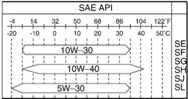
Engine oil requirements
Select an oil grade according to the average temperatures in the area where the outboard motor will be used.
Recommended engine oil:
YAMALUBE 4M FC-W or 4-stroke outboard motor oil
Recommended engine oil grade 1:
SAE 10W-30/10W-40/5W-30
API SE/SF/SG/SH/SJ/SL
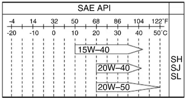
Recommended engine oil grade 2:
SAE 15W-40/20W-40/20W-50
API SH/SJ/SL
Engine oil quantity (without oil filter replacement):
6.0 L (6.34 US qt, 5.28 Imp.qt)
Engine oil quantity (with oil filter replacement):
6.3 L (6.66 US qt, 5.54 Imp.qt)
If oil grades listed under Recommended engine oil grade 1 are not available, select an alternative oil grade listed under Recommended engine oil grade 2.
Recommended engine oil grade 1
ZMU06854
Recommended engine oil grade 2
line
SAE API | Temperature Range | Value | | :--- | :--- | | -4 to 122°F | -20 to 50°C | | 122°F to 50°C | -20 to 50°C | | 15W-40 | 15W-40 | | 20W-40 | 20W-40 | | 20W-50 | 20W-50 | SH SJ SLZMU06855
EMU36360
Fuel requirements
EMU41331
Gasoline
Use a good quality gasoline that meets the minimum octane requirement. If knocking or pinging occurs, use a different brand of gasoline or premium unleaded fuel. Yamaha recommends that you use alcohol-free gasoline (see Gasoline with Ethanol) whenever possible.
The use of a poor quality gasoline may result in starting and running problems. If you encounter drivability problems, which you suspect could be related to the fuel you are using, we recommend that you switch to a recognized high quality brand of gasoline, such as a gasoline that is advertised as Top Tier Detergent Gasoline. Failure to comply with these recommendations may also result in unscheduled maintenance, fuel system damage, and internal engine damage.
Recommended fuel:
F225CA Regular unleaded gasoline
F250CA Regular unleaded gasoline
F250DET1 Regular unleaded gasoline
F300BET1 Premium unleaded gaso- line
F300CA Premium unleaded gasoline
FL250DET1 Regular unleaded gaso- line
FL300BET1 Premium unleaded gaso- line
LF225CA Regular unleaded gasoline
LF250CA Regular unleaded gasoline
LF300CA Premium unleaded gasoline
Min. pump octane number (PON):
F225CA 87
F250CA 87
F250DET1 87
F300BET1 89
F300CA 89
FL250DET1 87
FL300BET1 89
LF225CA 87
LF250CA 87
LF300CA 89
ECM01981
NOTICE
- Do not use leaded gasoline. Leaded gasoline can seriously damage the engine.
- Avoid getting water and contaminants in the fuel tank. Contaminated fuel can cause poor performance or engine damage. Use only fresh gasoline that has been stored in clean containers.
Gasoline with Ethanol
Two types of gasoline are commonly available in the U.S.A. and Canada for use in automobiles and boats: conventional gasoline without Ethanol and gasoline with Ethanol,
which is typically referred to as E10 gasoline. According to federal regulations, E10 gasoline may contain up to 10% Ethanol.
A high quality gasoline without Ethanol is the preferred fuel for your Yamaha outboard motor. However, if gasoline with Ethanol is the only fuel available in your area, your Yamaha outboard motor is calibrated to run properly on fresh E10 gasoline that meets the minimum octane requirement specified for this model.
ECM02401
NOTICE
Never use a gasoline for your outboard motor that contains more than 10% Ethanol, such as E15 which contains 15% Ethanol or E85 which contains 85% Ethanol, or gasoline containing any amount of Methanol. These fuels can cause starting and running problems, as well as serious fuel system and internal engine damage.
Gasoline containing ethanol has several properties that may cause boat fuel system problems.
- Ethanol is a strong solvent (cleaning agent) that can clean gum and varnish deposits from a boat's fuel system, particularly in older boats, as well as tanks and pipes used in gasoline distribution. These released deposits contaminate the fuel and can cause problems, such as clogged fuel filters, carburetors, or fuel injectors, which could result in engine damage.
- Ethanol may dissolve resins used in the construction of fiberglass fuel tanks. The dissolved resins contaminate the fuel and can cause problems, such as clogged fuel filters, carburetors, or fuel injectors, which could result in engine damage.
- Ethanol is hygroscopic (has a strong attraction to water). Therefore, any water
that inadvertently enters the fuel system, including moisture that is absorbed from the air, will mix with the ethanol in the gasoline. If the amount of water is excessive, the ethanol and water mixture will separate from the gasoline in a layer at the bottom of the fuel tank. This ethanol and water mixture is very corrosive to aluminum fuel tanks and fuel system components.
- The usable life span of E10 gasoline may be shorter than the normal length of off-season boat storage, causing starting and running problems related to stale fuel.
For more information on using fuel containing ethanol, visit: http://www.yamaha-motor.com
Gasoline Filtration
Yamaha outboard motors are equipped with internal fuel filters. However, excessive water or debris entering your engine's fuel system could prematurely clog the internal filters, causing starting and running problems, fuel system damage, and internal engine damage. Therefore, it is recommended that an external 10-micron water-separating fuel filter be installed on your boat and serviced frequently. Consult your authorized Yamaha dealer for a 10-micron filter that meets your engine's requirements.
EMU41341
Gasoline Additives
Gasoline blends change to meet automobile emission regulations and economic conditions. Additives, added by gasoline distributors, necessary for proper automobile engine operation and durability, may not be sufficient for typical boat applications. Intake valve and combustion chamber deposits may accumulate in boat engines more rapidly than encountered in automotive use. In addition, gasoline used for boating will typically
age longer between refills than gasoline used in automobiles, resulting in stale and unusable gasoline that may cause starting and running problems, fuel system damage, and internal engine damage.
Yamaha recommends the use of two Yamalube gasoline additives to reduce internal deposits and extend the storage life of gasoline. Continuous use of Yamalube Ring Free Fuel Additive Plus reduces harmful internal deposits. Yamalube Fuel Stabilizer & Conditioner Plus added to fresh gasoline will help protect the fuel system from varnishing while helping to keep the gasoline's octane level from decreasing excessively during storage. Other additives may also be available on the market that may have varying degrees of effectiveness. Consult your Yamaha dealer concerning what may work best for the locally available gasoline and environmental conditions.
EMU41350
Anti-fouling paint
A clean hull is required to maintain your boat's performance. Boats moored in the water should be protected from marine growth (barnacles, mussels, and marine plants). If approved by regulations for your area, the bottom of the hull can be coated with an anti-fouling paint to inhibit marine growth.
Anti-fouling paints specifically formulated for use on aluminum may be applied to the outboard motor. The original Yamaha paint surface may be scuffed lightly before applying anti-fouling paint, but do not remove the original paint. Removal of the original paint will increase the rate of corrosion.
ECM02410
NOTICE
Anti-fouling paint for fiberglass and wood may contain materials, such as copper,
graphite, and tin, that can cause corrosion if applied to aluminum boats and outboard motor components. Never apply these types of paint to your outboard motor because rapid corrosion damage could occur.
Sacrificial anodes are attached to the outboard motor to provide corrosion protection and must never be painted.
ECM02420
NOTICE
Painted sacrificial anodes will not provide corrosion protection.
EMU40301
Outboard motor disposal requirements
Never illegally discard (dump) the outboard motor. Yamaha recommends consulting the dealer about discarding the outboard motor.
EMU36352
Emergency equipment
Keep the following items onboard in case there is trouble with the outboard motor.
- A tool kit with assorted screwdrivers, pliers, wrenches (including metric sizes), and electrical tape.
- Waterproof flashlight with extra batteries.
- An extra engine shut-off cord (lanyard) with clip.
- Spare parts, such as an extra set of spark plugs.
Consult your Yamaha dealer for details.
EMU25222
Emission control information
EMU25230
North American models
This engine conforms to U.S. Environmental Protection Agency (EPA) regulations for marine SI engines. See the label affixed to your engine for details.
Specifications and requirements
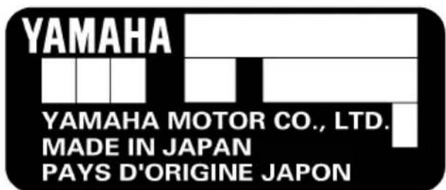
EMU31561
Approval label of emission control certificate
This label is attached to the bottom cowling.
New Technology; (4-stroke) MFI
- Approval label location
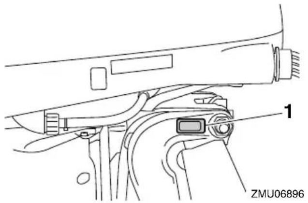
- Manufactured date label location
YAMAHA
Manufactured:

EMISSION CONTROL INFORMATION MFI
| THIS ENGINE CONFORMS TO : CALIFORNIA AND U.S. EPA EXHAUST REGULATIONS FOR SI MARINE ENGINES. REFER TO THE OWNER'S MANUAL FOR MAINTENANCE SPECIFICATIONS AND ADJUSTMENTS. MEETS U.S. EPA EVAP STANDARDS USING CERTIFIED COMPONENTS. | |||
| FAMILY: | FELs(HC+NOx / CO): | g/kW-hr | MAX POWER: kW |
| DISPLACEMENT: liters | IDLE SPEED: ±1 | rpm IN NEUTRAL | |
| SPARK PLUG: | SPARK PLUG GAP (mm): | ||
| FUEL: GASOLINE | VALVE LASH (mm) IN: | EX: | |
| YAMAHA MOTOR CO.,LTD. | |||
INFORMATION ANTIPOLLUTION MFI
| CE MOTEUR EST CONFORME AUX NORMES D'ÉMISSIONS : EPA DES É.-U. ET DE LA CALIFORNIE POUR MOTEURS MARINS À ÉTINCELLE. POUR LES SPECIFICATIONS ET LES RÉGLAGES À EFFECTUER, CONSULTEZ LE MANUEL DU PROPRIÉTAIRE. INSTALLÉ AVEC LES COMPOSANTS HOMOLOGUÉS, IL SATISFAIT AUX NORMES EVAP EPA DES É.-U. | ||
| FAMILLE : [___] | FELs(HC+NOx / CO): [___] g/kW-h | PUISS. MAX.: [___] kW |
| CYLINDRÉE : [___] litre | RALENTI: [___] ± [___] tr/mm AU POINT MORT | |
| BOUGIE : [___] | BOUGIE-ÉCARTEMENT (mm) : [___] | |
| CARBURANT : ESSENCE | JEU DE SOUPAPES (mm) ADM: [___] ECH: [___] | |
| YAMAHA MOTOR CO.,LTD. | ||
ZMU06895
EMU25263
Manufactured date label
This label is attached to the clamp bracket or the swivel bracket.
ZMU01701
EMU25274
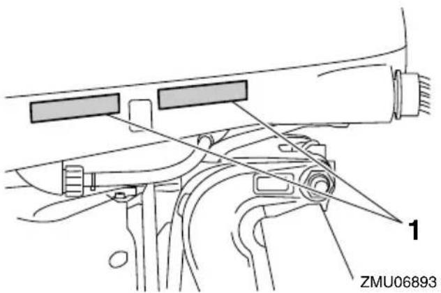
Star labels
Your outboard motor is labeled with a California Air Resources Board (CARB) star label. See below for a description of your particular label.
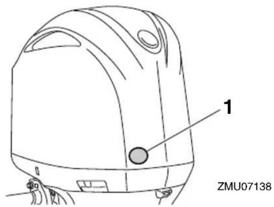
- Star labels location
EMU40330
One Star—Low Emission
The one-star label identifies engines that meet the Air Resources Board's Personal Watercraft and Outboard marine engine 2001 exhaust emission standards. Engines meeting these standards have 75% lower emissions than conventional carbureted two-stroke engines. These engines are equivalent to the U.S. EPA's 2006 standards for marine engines.

ZMU01702
EMU40340
Two Stars—Very Low Emission
The two-star label identifies engines that meet the Air Resources Board's Personal Watercraft and Outboard marine engine 2004 exhaust emission standards. Engines meeting these standards have 20% lower emissions than One Star-Low-Emission engines.

ZMU01703
EMU40350
Three Stars—Ultra Low Emission
The three-star label identifies engines that meet the Air Resources Board's Personal Watercraft and Outboard marine engine 2008 exhaust emission standards or the Sterndrive and Inboard marine engine 2003-2008 exhaust emission standards. Engines meeting these standards have 65% lower emissions than One Star-Low-Emission engines.

ZMU01704
EMU33861
Four Stars—Super Ultra Low Emission
The four-star label identifies engines that meet the Air Resources Board's Sterndrive and Inboard marine engine 2009 exhaust emission standards. Personal Watercraft and Outboard marine engines may also comply with these standards. Engines meeting these standards have 90% lower emissions than One Star-Low-Emission engines.

ZMU05663
EMU2579Y
Components diagram
TIP:
* May not be exactly as shown; also may not be included as standard equipment on all models (order from dealer).
F225, LF225, F250, LF250, F300, LF300, F250D1, FL250D1, F300B1, FL300B1
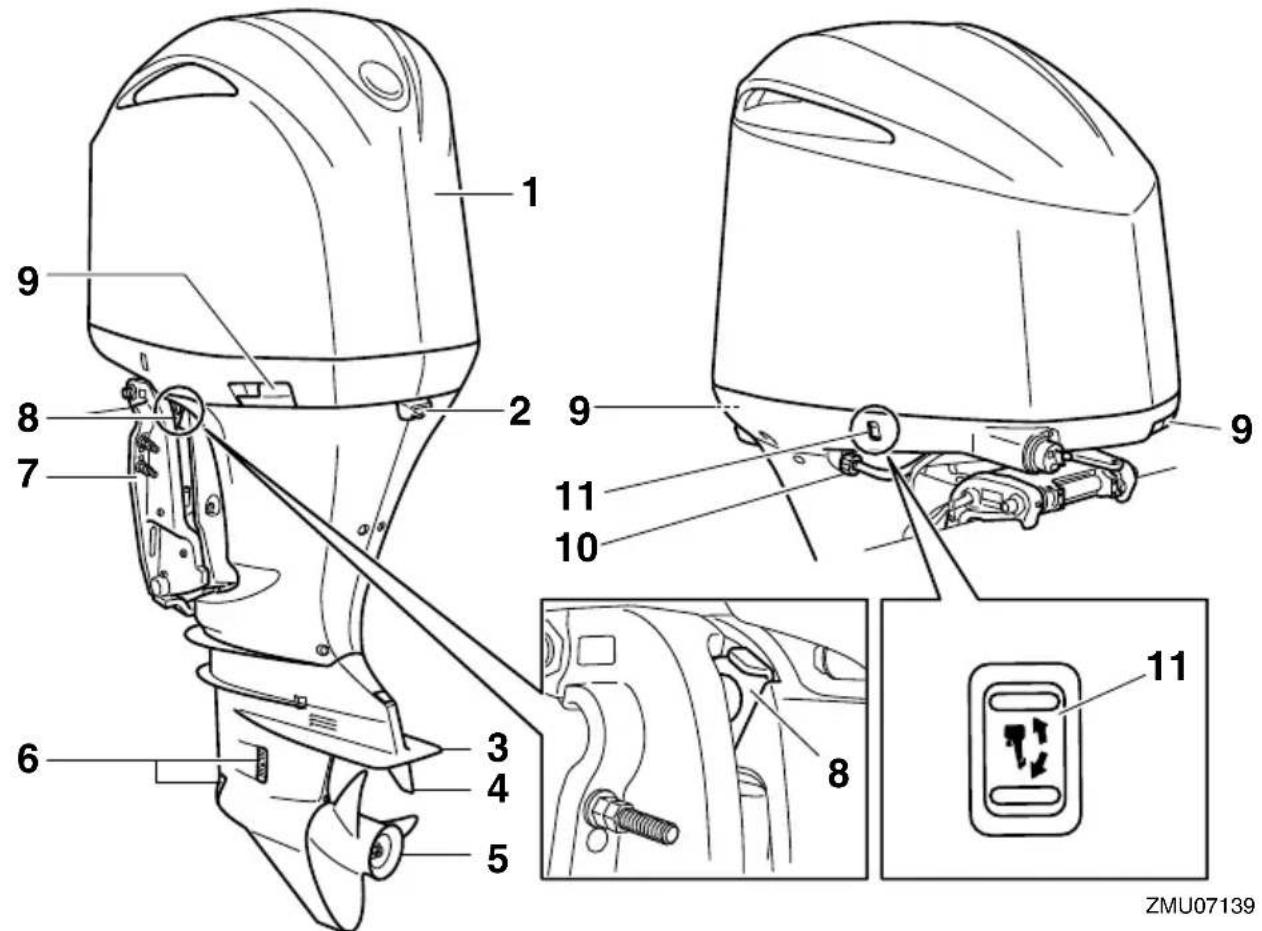
- Top cowling
- Idle hole
- Anti-cavitation plate
- Trim tab (anode)
- Propeller*
- Cooling water inlet
- Clamp bracket
- Tilt support lever
- Cowling lock lever
- Flushing device
- Power trim and tilt switch

- Ignition coil
- Oil dipstick
- Cowling lock lever
- Power trim and tilt switch
- Flushing device
- Oil level plug
- Gear oil drain screw
- Cooling water inlet
- Anode
- Power trim and tilt unit
- Fuel filter
- Fuse box
- Oil filler cap
ZMU07231
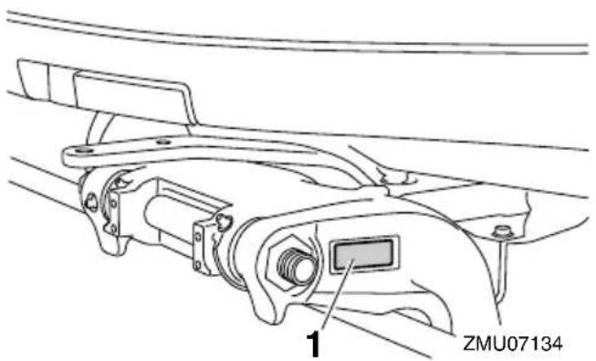
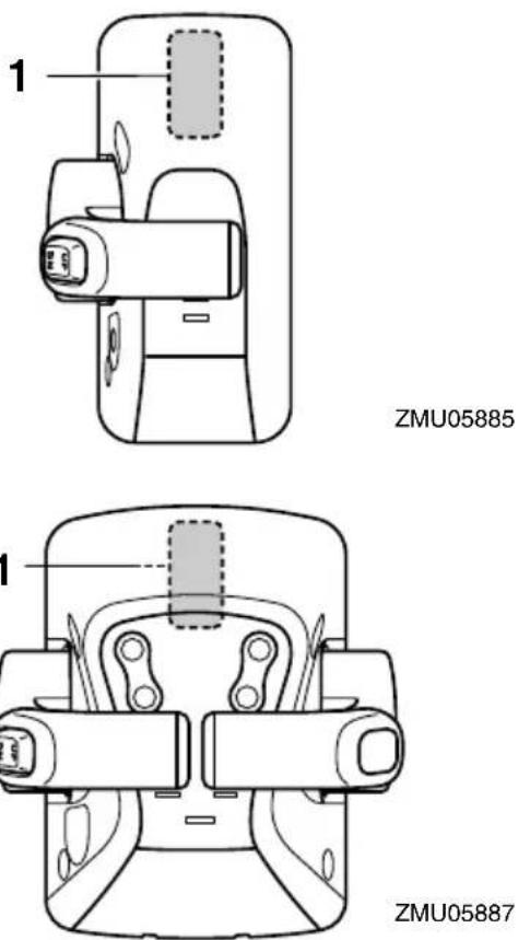
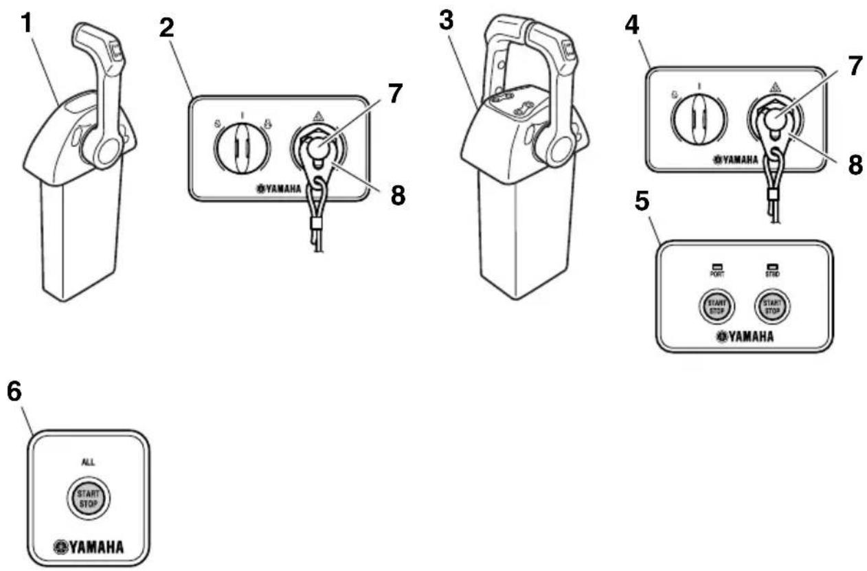
- Digital electronic control (single type)*
- Switch panel (for use with single type)*
- Digital electronic control (twin type)*
- Switch panel (for use with twin type)*
- Start/Stop switch panel (for use with twin type)*
- All Start/Stop switch panel (for use with twin type)*
- Engine shut-off switch
- Clip
1
2
3
4
5
6
7
ZMU07205
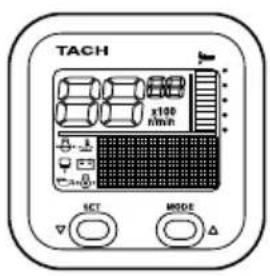
- Tachometer unit (Square type) ^*
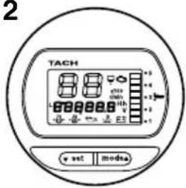
- Tachometer unit (Round type)*
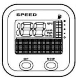
- Speedometer unit (Square type) ^*
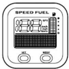
- Speed & fuel meter unit (Square type)*
- Speed & fuel meter unit (Round type)*
- Fuel management meter unit (Square type)*
- Command Link Plus Display*
EMU34961
Digital Electronic Control box
The digital electronic control box actuates the shifter, the throttle and remote electrical operations. Make sure that the active indicator lights and that the digital electronic control unit is correctly connected to the outboard motor.
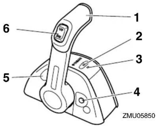
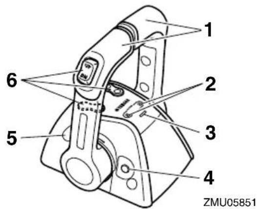
- Control lever
- Digital electronic control-active indicator
- Digital electronic control-alert indicator
- Free throttle switch
- Throttle friction adjuster
- Power trim and tilt switch
EMU34973
Digital electronic control-active indicator
The digital electronic control-active indicator indicates that the digital electronic control system is in the operating state.
● Lights: Operation of both shift and throttle possible.
- Blinks (when the gear shift is in neutral only): Shift not operable. Only throttle operation available.
- Off: Shift and throttle not operable.
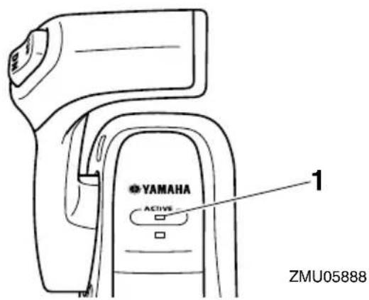
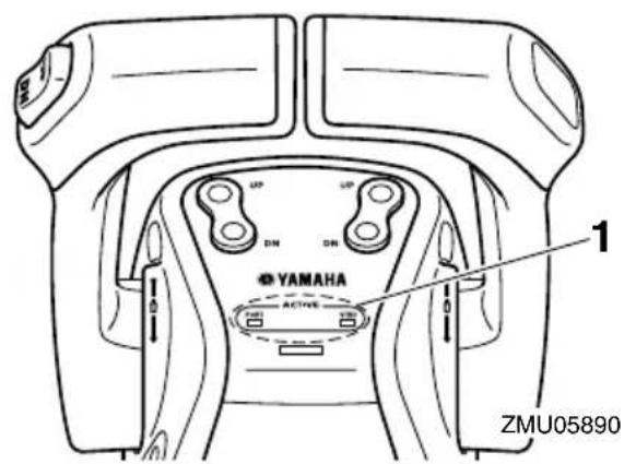
- Digital electronic control-active indicator
EMU34984
Digital electronic control-alert indicator
The digital electronic control-alert indicator lights when trouble occurs in the connection between the digital electronic control and outboard motor. Consult your Yamaha dealer for details.
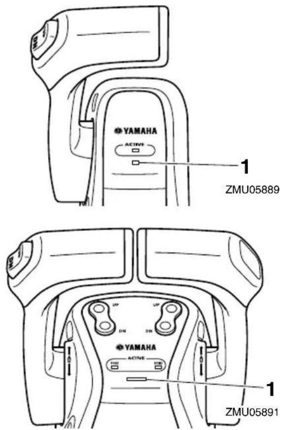
- Digital electronic control-alert indicator
EMU34992
Control lever
Moving the lever forward from the neutral position engages forward gear. Pulling the lever back from neutral engages reverse. The engine will continue to run at idle until the lever is moved 22.5° (a detent can be felt). Moving the lever farther opens the throttle, and the engine will begin to accelerate.
Digital electronic control for twin type has the function of automatically synchronizing the engine speeds of both engines of the port and starboard sides.
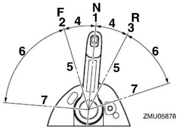
- Neutral "N"
- Forward "F"
- Reverse "R
- Shift
- Fully closed
- Throttle
- Fully open
EMU35001
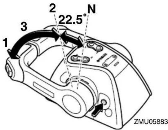
Free throttle switch
In neutral, keep this switch pressed, move the control lever forward, and release the switch after the digital electronic control-active indicator starts blinking. While the indicator blinks, you can open or close the throttle. This can also be done when the control lever is set in reverse.
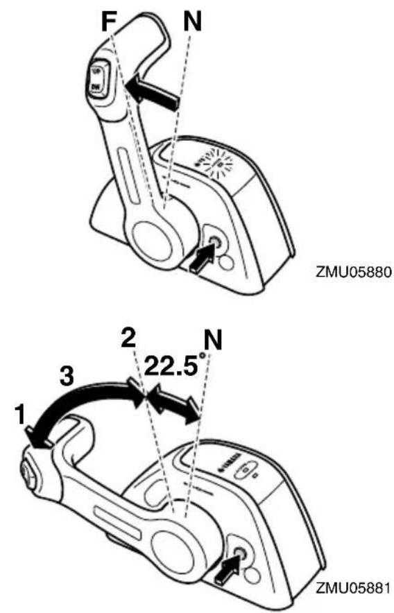
- Fully open
- Fully closed
- Free accelerator

- Fully open
- Fully closed
-
Free accelerator
-
The free throttle switch can only be used when the control lever is in the neutral position.
- During operation the digital electronic control-active indicator changes from continuously lit to blinking. When the indicator starts blinking, the throttle begins to open after the control lever is moved at least 22.5°.
- After using the free throttle switch, return the control lever to the neutral position. The free throttle switch will return automatically to its set position. The digital electronic control-active indicator will change from blinking to continuously lit and the digital electronic control will then engage forward and reverse normally.
EMU35250
Throttle friction adjuster
A friction device provides adjustable resistance to movement of the control lever, and can be set according to operator preference. To increase resistance, turn the adjuster clockwise. To decrease resistance, turn the adjuster counterclockwise.
EWM01770
WARNING
- If the friction is too small, the control lever could move freely and cause an accident.
- Do not overtighten the friction adjuster. If there is too much resistance, it could be difficult to move the control lever, which could result in an accident.
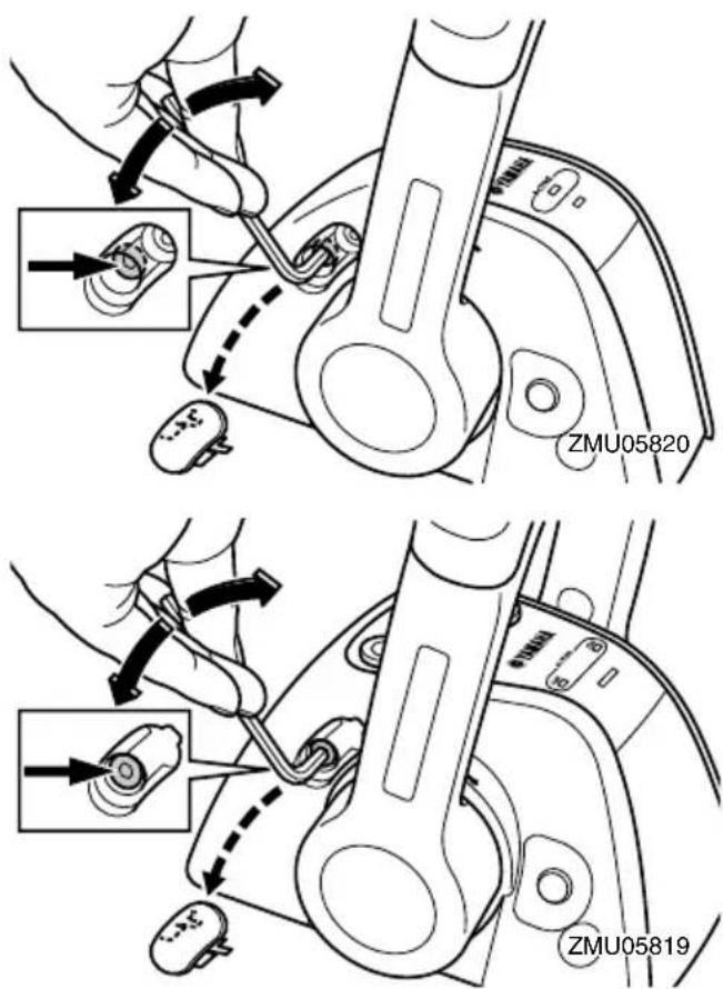
When constant speed is desired, tighten the adjuster to maintain the desired throttle setting.
EMU25995
Engine shut-off cord (lanyard) and clip
The clip must be attached to the engine shut-off switch for the engine to run. The cord should be attached to a secure place on the operator's clothing, or arm or leg. Should the operator fall overboard or leave the helm, the cord will pull out the clip, stopping ignition to
the engine. This will prevent the boat from running away under power. WARNING! Attach the engine shut-off cord to a secure place on your clothing, or your arm or leg while operating. Do not attach the cord to clothing that could tear loose. Do not route the cord where it could become entangled, preventing it from functioning. Avoid accidentally pulling the cord during normal operation. Loss of engine power means the loss of most steering control. Also, without engine power, the boat could slow rapidly. This could cause people and objects in the boat to be thrown forward. [EWM00122]
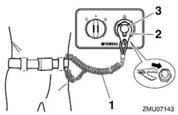
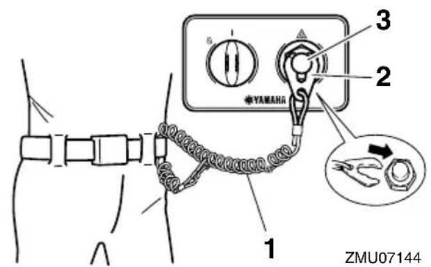
- Engine shut-off cord (lanyard)
- Clip
- Engine shut-off switch
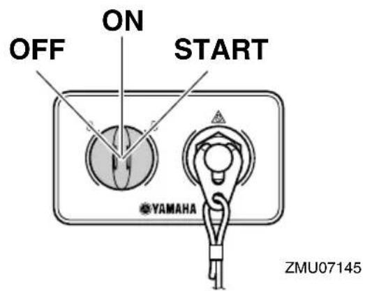
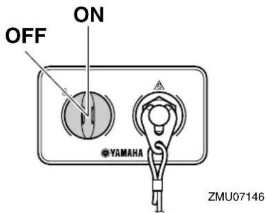
EMU41551
Main switch
The main switch controls the ignition system; its operation is described below.
- OFF " (off)
With the main switch in the "OFF(off) position, the electrical circuits are off, and the key can be removed.
- "ON" (on)
With the main switch in the "ON(on) position, the electrical circuits are on, and the key cannot be removed. The engine can be started by pressing the Start/Stop button.
- \$START " (start)
With the main switch in the "START" position, the starter motor turns to start the engine. When the key is released, it returns automatically to the "ON" position.
EMU41621
Start/Stop switch panel
The engine can be started or turned off by
pressing the Start/Stop button. For twin type, it is possible to start or turn off individual engine. The indicator for the corresponding engine will come on.
- PORT:Port side engine
• STBD:Starboard side engine
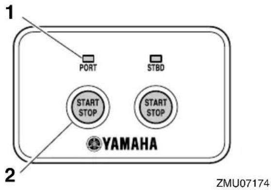
- Indicator
- Start/Stop button
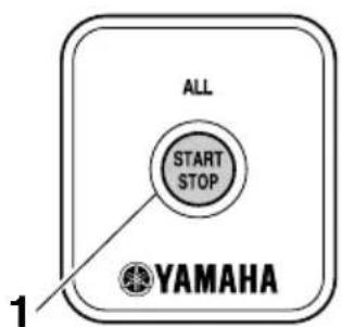
EMU41631
All Start/Stop switch panel
The Start/Stop button allows all engines to start or turn off.
ZMU07176
- All Start/Stop button
EMU35153
Power trim and tilt switch on digital electronic control
The power trim and tilt system adjusts the outboard motor angle in relation to the trans- som. Pressing the switch "UP(up) trims the outboard motor up, and then tilts it up. Pressing the switch "DN(down) tilts the outboard motor down and trims it down. When the switch is released, the outboard motor will stop in its current position. For instructions on using the power trim and tilt switch, see pages 64 and 66.
EMU26155
Power trim and tilt switch on bottom cowling
The power trim and tilt switch is located on the side of the bottom cowling. Pushing the switch "UPup) trims the outboard motor up, and then tilts it up. Pushing the switch "DN (down) tilts the outboard motor down and trims it down. When the switch is released, the outboard motor will stop in its current position.
For instructions on using the power trim and tilt switch, see page 66.
EWM01031
WARNING
Use the power trim and tilt switch located on the bottom cowling only when the boat is at a complete stop with the engine off. Attempting to use this switch while the boat is moving could increase the risk of falling overboard and could distract the operator, increasing the risk of collision with another boat or an obstacle.
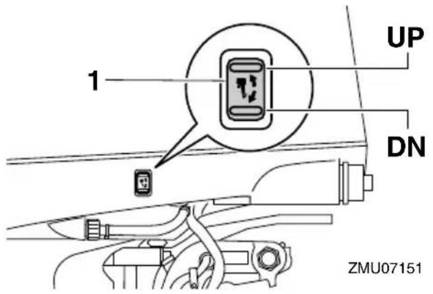
- Power trim and tilt switch
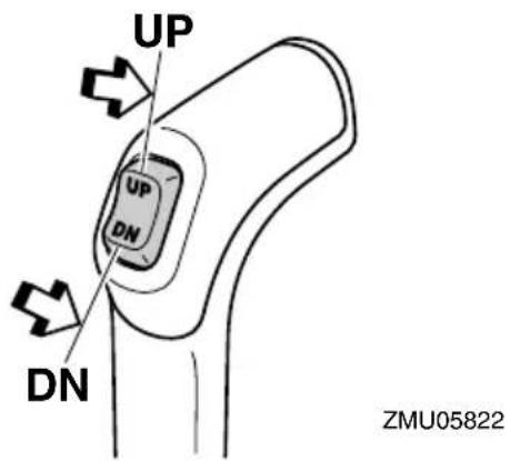
EMU35160
Power trim and tilt switches (twin type)
The power trim and tilt system adjusts the outboard motor angle in relation to the transom. Pushing the switch "UP(up) trims the outboard motor up, and then tilts it up. Pressing the switch "DN(down) tilts the outboard motor down and trims it down. When the switch is released, the outboard motor will stop in its current position.
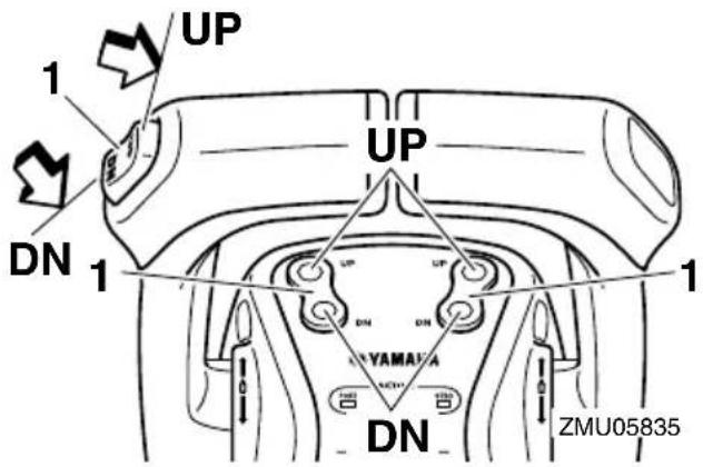
-
Power trim and tilt switch
-
On the twin engine control, the switch on the control grip controls both outboard motors at the same time.
- For instructions on using the power trim and tilt switches, see pages 64 and 66.
EMU26244
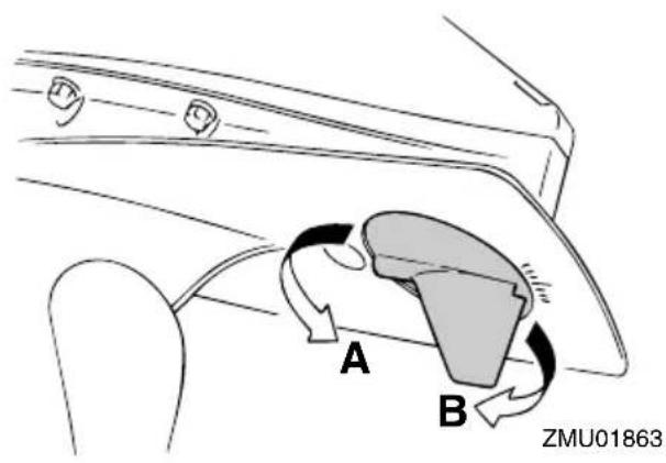
Trim tab with anode
EWM00840

WARNING
An improperly adjusted trim tab could cause difficult steering. Always test run after the trim tab has been installed or replaced to be sure steering is correct. Be sure you have tightened the bolt after adjusting the trim tab.
The trim tab should be adjusted so that the steering control can be turned to either the right or left by applying the same amount of force.
If the boat tends to veer to the left (port side), turn the trim tab rear end to the port side "A" in the figure. If the boat tends to veer to the right (starboard side), turn the trim tab end to the starboard side "B" in the figure.
ECM00840
NOTICE
The trim tab also serves as an anode to protect the engine from electrochemical corrosion. Never paint the trim tab as it will become ineffective as an anode.
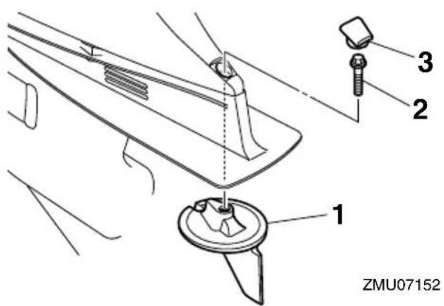
- Trim tab
- Bolt
- Cap
Bolt tightening torque: 42 Nm (4.28 kgf-m, 31 ft-lb)
EMU26341
Tilt support lever for power trim and tilt model
To keep the outboard motor in the tilted up position, lock the tilt support lever to the clamp bracket.
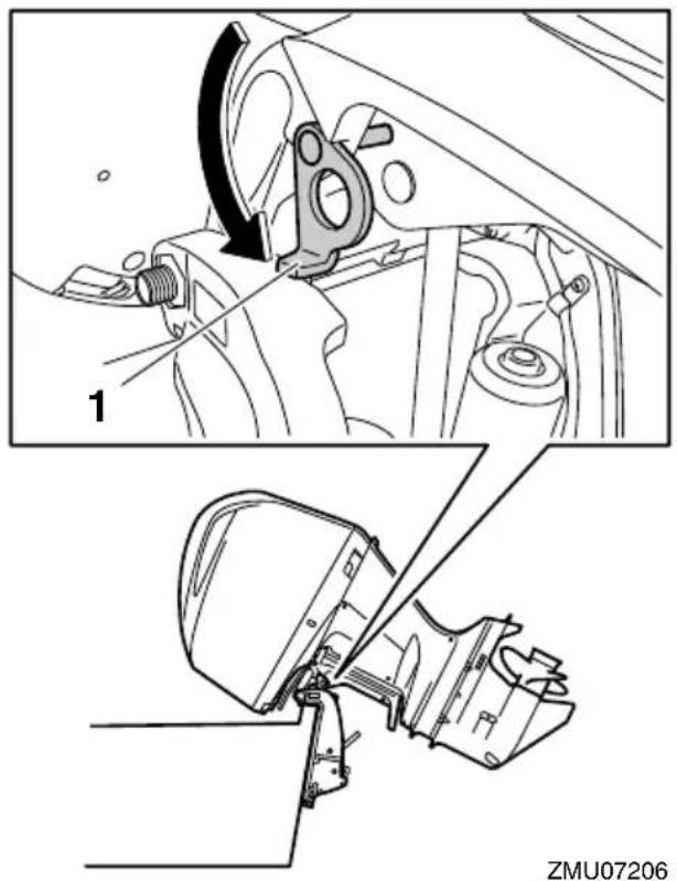
- Tilt support lever
ECM00660
NOTICE
Do not use the tilt support lever or knob when trailering the boat. The outboard motor could shake loose from the tilt support and fall. If the motor cannot be trailered in the normal running position, use an additional support device to secure it in the tilt position.
EMU40760
Cowling lock lever
The cowling lock levers are used to secure the top cowling.

natural_image
Technical diagram of a mechanical assembly with labeled component 1 (no text or symbols beyond label)- Cowling lock lever

- Cowling lock lever(s)
EMU40802
Flushing device
The flushing device is used to clean the cooling water passages of the outboard motor
Components
using a garden hose and tap water. For instructions on using the flushing device, see page 71.
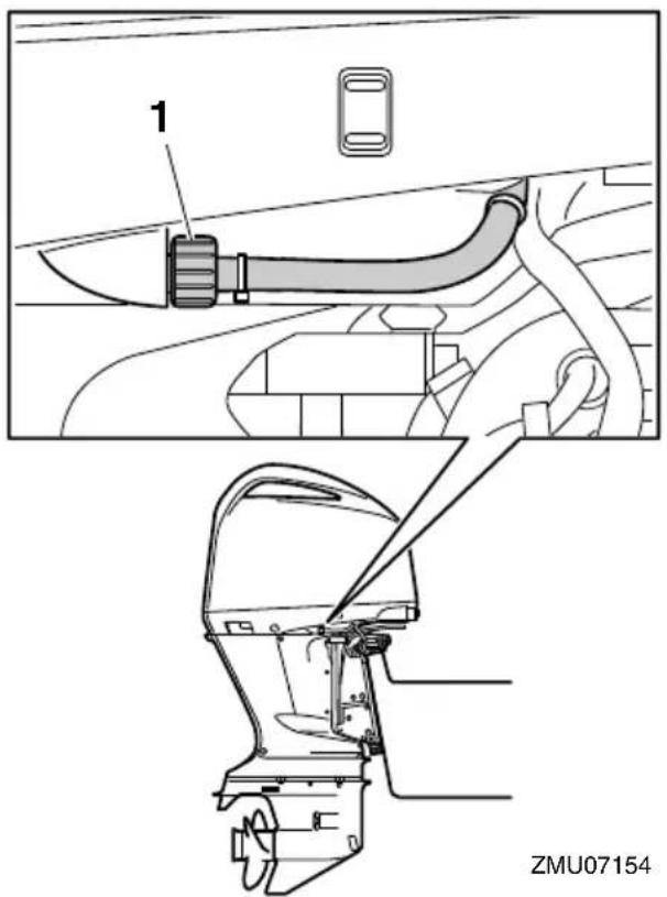
- Flushing device
EMU40822
Fuel filter
The fuel filter functions to remove foreign material and separate water from the fuel. If water separated from the fuel exceeds a specific volume, the alert system will activate. For further information, see page 48.

- Fuel filter
TIP:
Adding an in-line 10-micron fuel filter has been shown to greatly reduce the chance of fuel contamination problems. Consult your dealer for information about Yamaha 10-micron fuel filters if your boat does not have one.
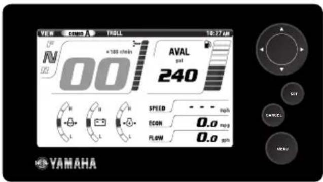
EMU41542
Command Link Plus Display
The Command Link Plus Display (hereinafter called the Multi-Display) shows engine status and alert information. The display of optional items can be changed. This manual mainly covers the alert display. For information on other settings or changing the display, see the Command Link Plus Display owner's manual.
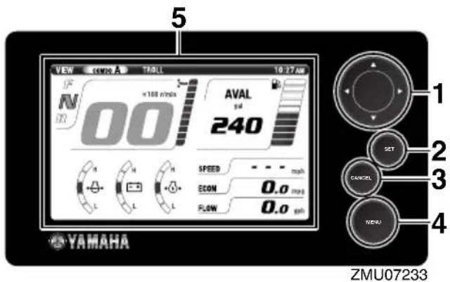
- Arrow keys
- Set button
- Cancel button
- Menu button
- Display
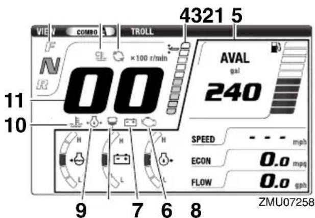
- Shift position display
- Engine warm-up indicator
- Engine synchronization indicator
- Trim meter
-
Optional items
-
Engine trouble-alert indicator
- Low battery voltage-alert indicator
- Water separator-alert indicator
- Low oil pressure-alert indicator
- Overheat-alert indicator
- Tachometer
EMU41650
Engine warm-up indicator
This indicator appears while the engine is being warmed up and goes off when warming-up is finished.

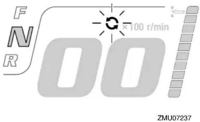
EMU41660
Engine synchronization indicator
In twin types, this display appears while the engines are under engine synchronization control. It goes off when engine synchronization control is released.
EMU41680
Overheat alert
If the engine temperature rises too high while cruising, the pop-up window will appear.
Instruments and indicators
Press the "set" button to change to normal display, and the overheat-alert indicator will start to blink. The engine speed will automatically decrease to about 2000 r/min.
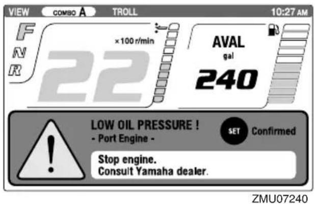
(set) button to change to normal display, and the low oil pressure-alert indicator will start to blink. The engine speed will automatically decrease to about 2000 r/min.
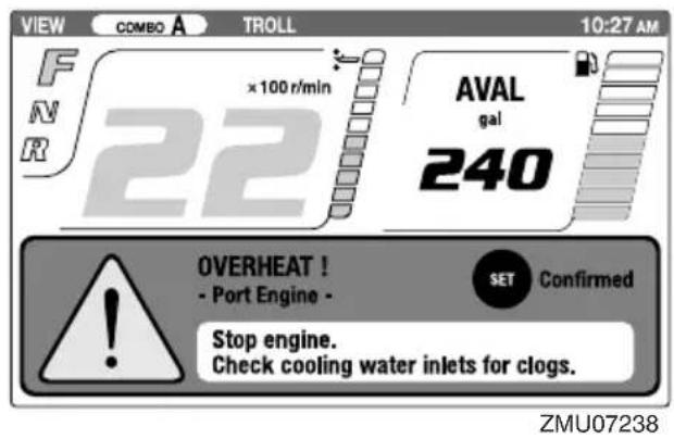
Stop the engine immediately if the buzzer sounds and the overheat alert device has activated. Check the cooling water inlet for clogging.
ECM01592
NOTICE
- Do not continue to run the engine if the overheat-alert indicator blinks. Serious engine damage will occur.
- Do not continue to operate the engine if a alert device has activated. Consult your Yamaha dealer if the problem cannot be located and corrected.
Stop the engine immediately if the buzzer sounds and the low oil pressure-alert device has activated. Check the engine oil quantity and replenish oil if necessary. If the alert device has activated while the appropriate engine oil quantity is maintained, consult your Yamaha dealer.
ECM01601
NOTICE
Do not continue to run the engine if the low oil pressure alert device has activated. Serious engine damage will occur.
EMU41700
Water separator alert
The pop-up window will appear if water has accumulated in the water separator (fuel filter) while cruising. Press the "set(set) but-
EMU41690
Low oil pressure-alert
If the engine oil pressure drops too low, the pop-up window will appear. Press the "set
ton to change to normal display, and the water separator-alert indicator will start to blink.
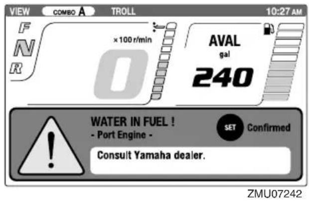
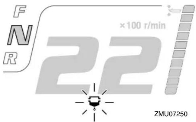
Stop the engine immediately and see page 96 of this manual to drain the water from the fuel filter. Get back to the port soon and consult a Yamaha dealer immediately.
ECM00910
NOTICE
Gasoline mixed with water could cause damage to the engine.
EMU41720
Low battery voltage-alert
The pop-up window will be displayed if the battery voltage drops. Press the "set(set) button will change to the normal display and the battery voltage-alert indicator will start to blink.
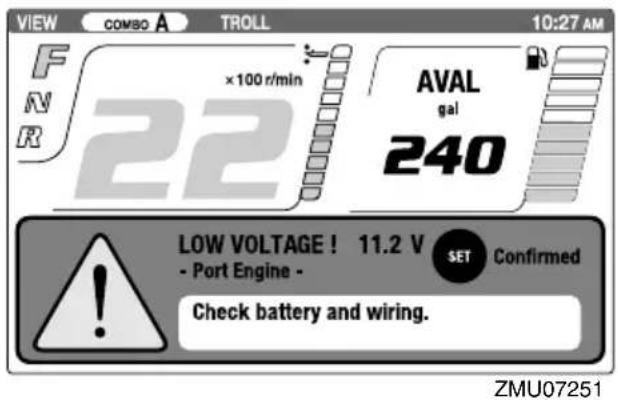
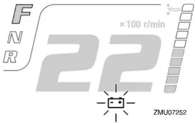
Get back to the port soon if the low battery voltage-alert device has activated. For charging the battery, consult your Yamaha dealer.
EMU41710
Engine trouble alert
The pop-up window will appear if the engine malfunctions while cruising. Press the "set (set) button to change to normal display, and the engine trouble-alert indicator will start to blink.
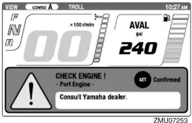
Return to port and consult a Yamaha dealer immediately.
EMU40792
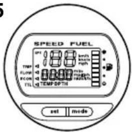
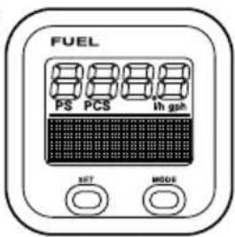
Command Link Multifunction Meters
There are 6 types of Command Link meters: tachometer unit (square and round types), speedometer unit (square type), speed & fuel meter unit (square and round types), and fuel management meter (square type). The indicator system is slightly different between the round and square types. Check the model and type of your unit carefully. This manual describes mainly the alert indicators. For more details on setting meters or changing indicator systems, see the operation manual for the meters.
EMU41164
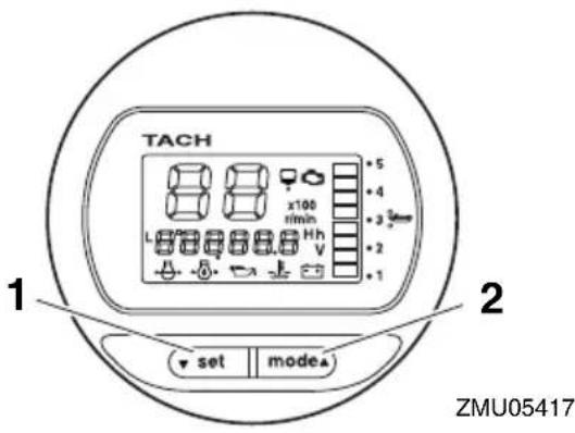
Command Link Multifunction Tachometer
The tachometer shows the engine speed and has functions of trim meter, adjusting trolling speed, cooling water/engine temperature display, battery voltage display, total hour/trip hour display, oil pressure display, water detection alert, engine trouble alert, and periodic maintenance notification. If the cooling water pressure sensor is installed, the unit can also show the cooling water pressure display. However, even if the cooling water pressure sensor is not installed, the cooling water pressure display can be shown by connecting an optional sensor to the unit. For the optional sensor, consult your Yamaha dealer. The tachometer unit is available in round and square types. Check your tachometer unit type.
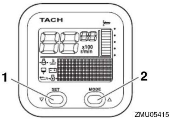
- Set button
- Mode button
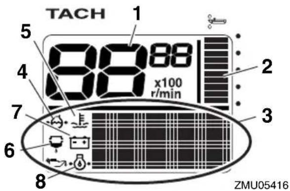
- Tachometer
- Trim meter
- Multifunction display
- Cooling water pressure
- Cooling water/engine temperature
- Water detection-alert indicator
- Battery voltage
- Oil pressure (4-stroke models)
- Set button
- Mode button
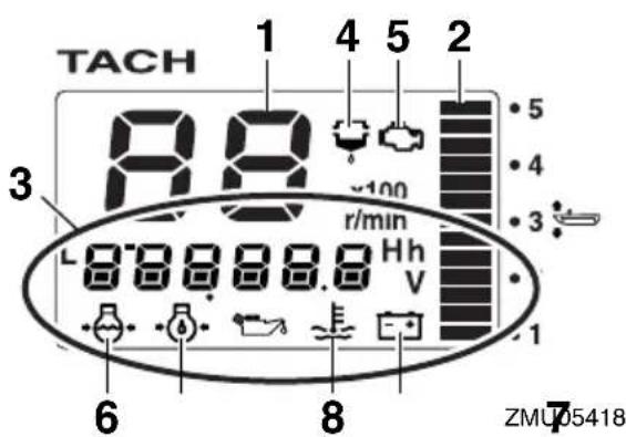
- Tachometer
- Trim meter
- Multifunction display
- Water detection-alert indicator
- Engine trouble alert/maintenance indicator
- Cooling water pressure
- Oil pressure (4-stroke models)
- Cooling water/engine temperature
- Battery voltage
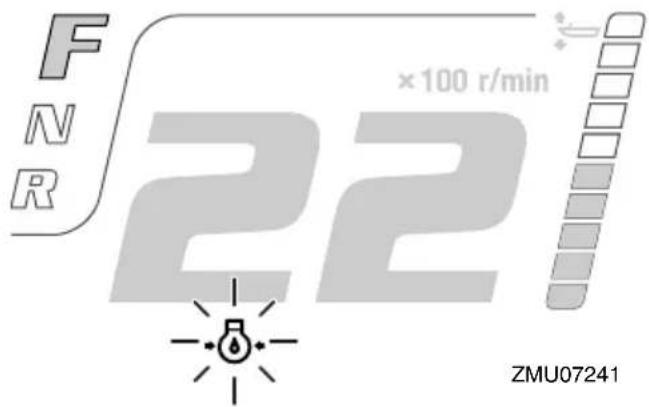
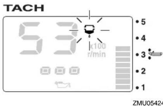
EMU36130
Low oil pressure-alert
If the engine oil pressure drops too low, the low oil pressure-alert indicator will start to blink, and the engine speed will automatically decrease to about 2000 r/min.
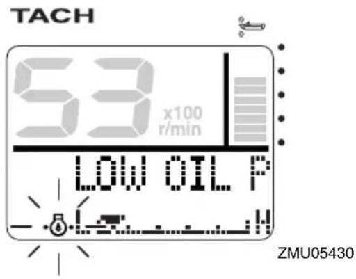
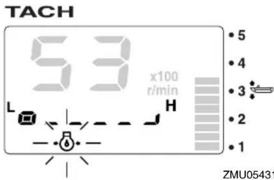
Stop the engine immediately if the buzzer sounds and the low oil pressure-alert indicator blinks. Check the engine oil quantity and replenish oil if necessary. If the alert device has activated while the appropriate engine oil quantity is maintained, consult your Yamaha dealer.
ECM01601
NOTICE
Do not continue to run the engine if the low oil pressure alert device has activated. Serious engine damage will occur.
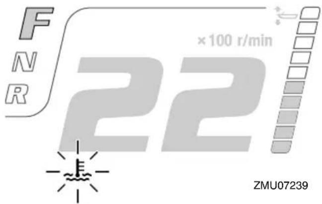
EMU36221
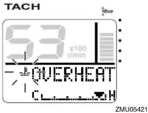
Overheat alert
If the engine temperature rises too high while cruising, the overheat-alert indicator will start to blink. The engine speed will automatically decrease to about 2000 r/min.
dealer immediately.

Stop the engine immediately if the buzzer sounds and the overheat alert device has activated. Check the cooling water inlet for clogging.
ECM01592
NOTICE
- Do not continue to run the engine if the overheat-alert indicator blinks. Serious engine damage will occur.
- Do not continue to operate the engine if a alert device has activated. Consult your Yamaha dealer if the problem cannot be located and corrected.
EMU36150
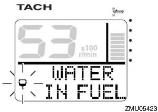
Water separator alert
This indicator will blink if water has accumulated in the water separator (fuel filter) while cruising. In such an event, stop the engine immediately and see page 96 of this manual to drain the water from the fuel filter. Get back to the port soon and consult a Yamaha
ECM00910
NOTICE
Gasoline mixed with water could cause damage to the engine.
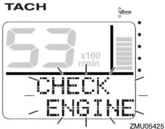
EMU36160
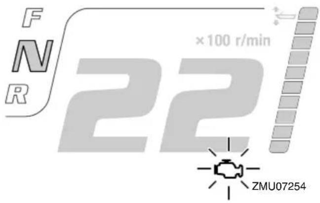
Engine trouble alert
This indicator will blink if the engine malfunctions while cruising. Get back to the port soon and consult a Yamaha dealer immediately.
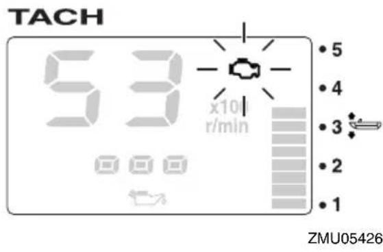
ECM00920
NOTICE
In such an event, the engine will not operate properly. Consult a Yamaha dealer immediately.
EMU36170
Low battery voltage-alert
If the battery voltage drops, the low battery voltage-alert indicator and the battery voltage value will start to blink. Get back to the port soon if the low battery voltage-alert device has activated. For charging the battery, consult your Yamaha dealer.

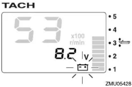
EMU41033
Command Link Multifunction Speed & Fuel Meter
The speed & fuel meter unit shows the boat speed and has the functions of fuel meter, total fuel consumption display, fuel economy display, fuel flow display, and system voltage display. The chosen display is selected using the "set(set) and " (mode) buttons as described in this section. If the speed sensor is installed, the unit can also show the trip display. However, even if the speed sensor is not installed, the trip display can be shown by connecting an optional sensor to the unit. In addition, if optional sensors are connected to the unit, water surface temperature display, depth display, and clock will also be available. For the optional sensors, consult your Yamaha dealer.
The speed & fuel meter unit is available in round and square types. Check your speed & fuel meter unit type.
After the main switch is first turned to the "On" position, all of the displays come on as a test. After a few seconds, the unit will change to normal operation.
For more information, see the operation manual for the meters.
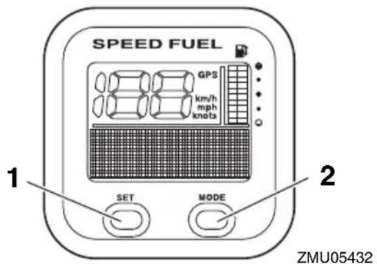
- Set button
- Mode button
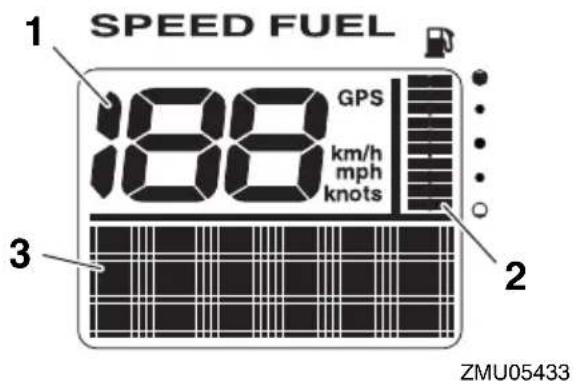
- Speedometer
- Fuel meter
- Multifunction display
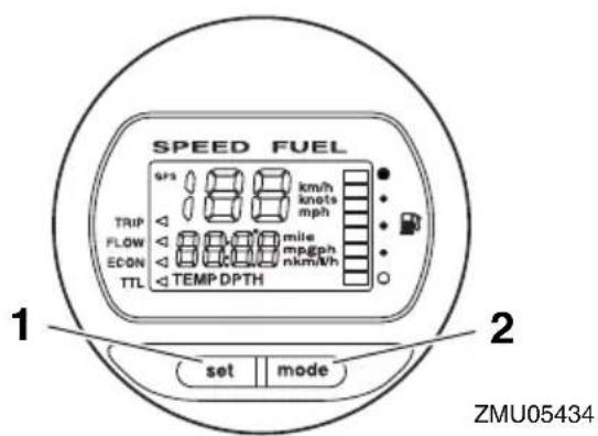
- Set button
- Mode button
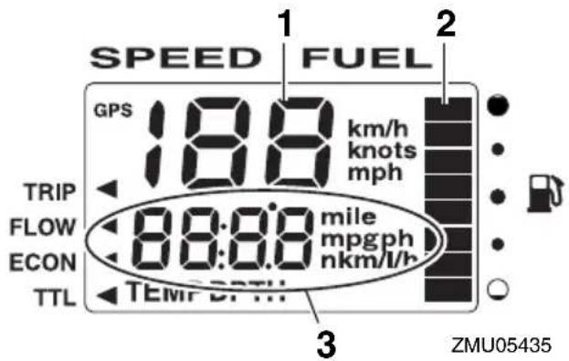
- Speedometer
- Fuel meter
- Multifunction display
EMU41042
Command Link Multifunction Speedometer
The speedometer unit shows the boat speed and has functions of fuel meter and system voltage display. The chosen display is selected using the "set (set) and "mode (mode) buttons as described in this section. In addition, the speedometer can show the desired unit of measurement such as km/h, mph, or knots. If the speed sensor is installed, the unit can also show the trip display. However, even if the speed sensor is not installed, the trip display can be shown by connecting an optional sensor to the unit. In addition, if optional sensors are connected to the unit, water surface temperature display, depth display, and clock will also be available. For the optional sensors, consult your Yamaha dealer.
After the main switch is first turned to the "Ö(ON) position, all of the displays come on as a test. After a few seconds, the unit will change to normal operation.
For more information, see the operation manual for the meters.
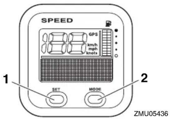
- Set button
- Mode button
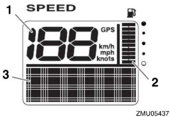
- Speedometer
- Fuel meter
- Multifunction display
EMU41022
Command Link Multifunction Fuel Management Meter
The fuel management meter has the functions of fuel flow meter, total consumption display, fuel economy display, and remaining fuel display. The chosen display is selected using the "set" and " (mode) buttons as described in this section.
After the main switch is first turned to the "ö(n) position, all of the displays come on as a test. After a few seconds, the unit will change to normal operation.
For more information, see the operation
manual for the meters.
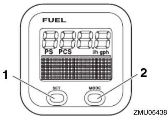
- Set button
- Mode button
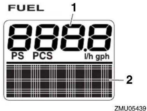
- Fuel flow meter
- Multifunction display
EMU41730
Optional meters
Various meters can be installed onto the outboard motor according to user preference. For details, consult your Yamaha dealer.
Analog tachometer
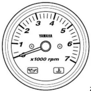
ZMU07245
Trim meter
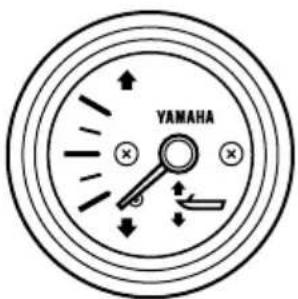
ZMU04581
EMU26803
Alert system
ECM00091
NOTICE
Do not continue to operate the engine if a alert device has activated. Consult your Yamaha dealer if the problem cannot be located and corrected.
EMU35184
Digital Electronic Control alert
If during operation of the outboard motor any communication troubles between the digital electronic control and the outboard motor occur, the alert indicator will light. Even if there is no symptom of trouble on shifting or throttle, get back to the port soon and have a Yamaha dealer inspect or repair the outboard motor.
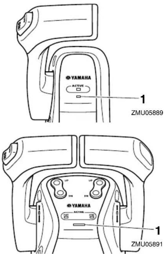
1. Digital electronic control-alert indicator
EMU41743
Overheat alert
This engine has an overheat-alert device. If the engine temperature rises too high, the alert device will activate.
- The engine speed will automatically decrease to about 2000 r/min.
- The overheat-alert indicator of the Command Link Multifunction Tachometer will light or blink.
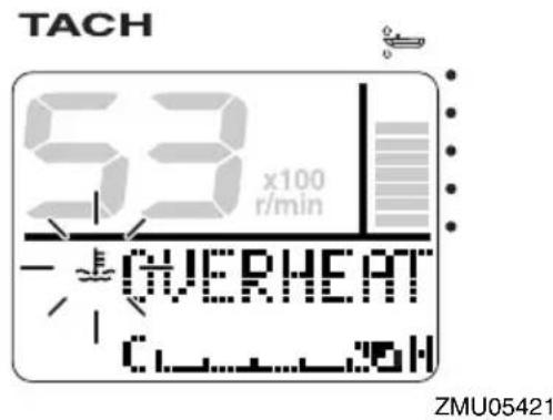

- The pop-up window will appear on the Multi-Display.
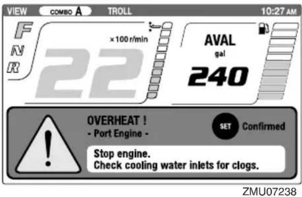
• The buzzer will sound.
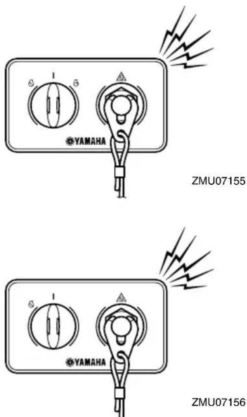
If the alert system has activated, stop the engine and check the cooling water inlets:
- Check trim angle to be sure that the cooling water inlet is submerged.
- Check the cooling water inlet for clogging.
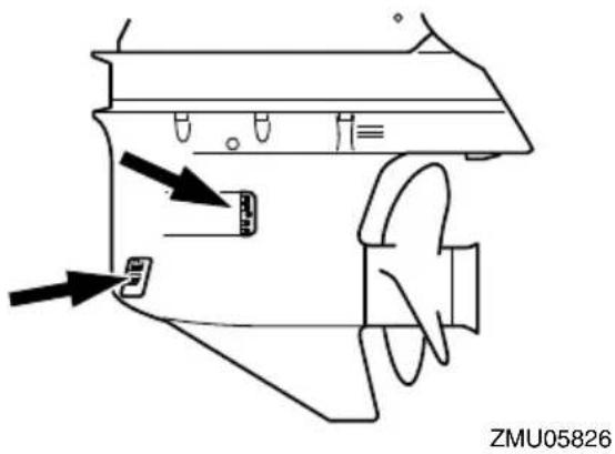
Twin engine drive users:
If the overheat alert system of one engine activates, the engine will slow down. To switch off the alert activation on the engine not affected by overheating, turn off the main switch of the engine overheating. If the alert system has activated, stop the engine and tilt the outboard motor up to check the cooling water inlet for clogging. If the alert system has still activated, tilt the overheated outboard motor up and return to the port.
EMU41753
Low oil pressure alert
If the oil pressure drops too low, the alert device will activate.
- The engine speed will automatically decrease to about 2000 r/min.
- The low oil pressure-alert indicator of the Command Link Multifunction Tachometer will light or blink.
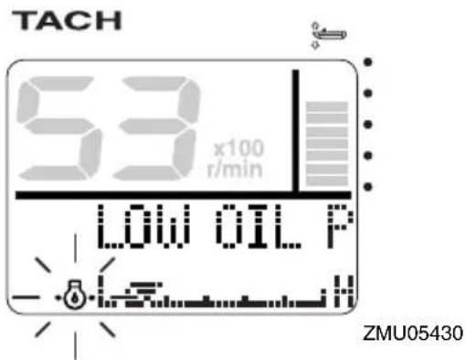
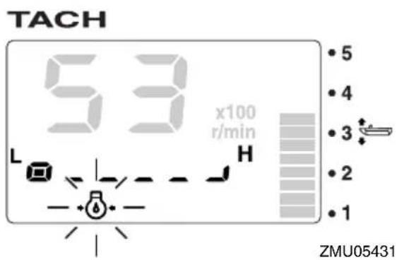
- The pop-up window will appear on the Multi-Display.
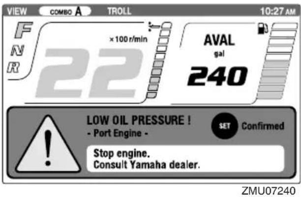
- The buzzer will sound.
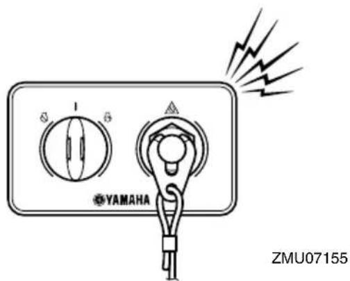
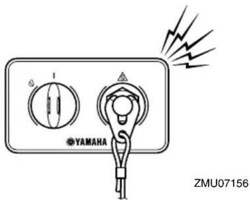
If the alert device has activated, stop the engine as soon as it is safe to do so. Check the oil level and add oil as needed. If the oil level is correct and the alert device does not switch off, consult your Yamaha dealer.
Twin engine drive users:
If the low oil pressure alert system of one engine activates, both engines will slow down and the buzzer will sound. To switch off the alert activation on the engine not affected by low oil pressure, turn off the main switch of the engine with the low oil pressure.
EMU41762
Water separator alert
The outboard motor is equipped with a water separator alert system. If water separated from the fuel exceeds a specific volume, the alert system will activate.
- The water separator-alert indicator of the Command Link Multifunction Tachometer will come on or blink.
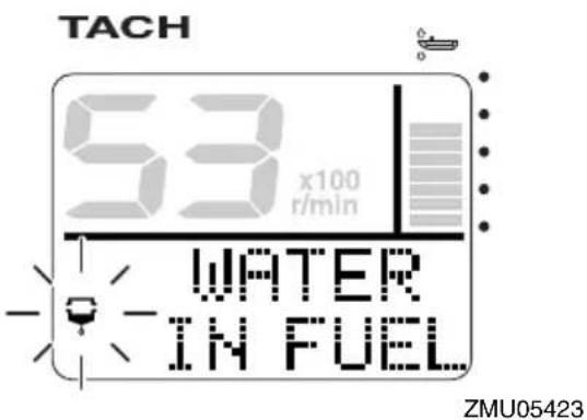
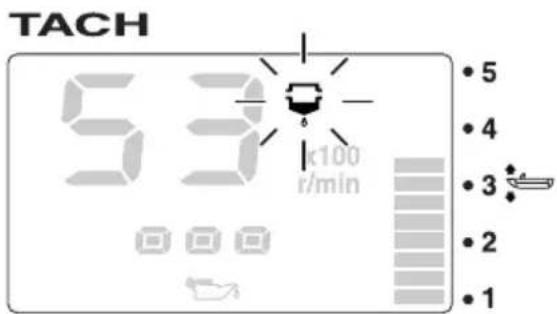
ZMU05424
- The pop-up window will appear on the Multi-Display.
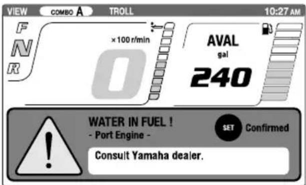
ZMU07242
- The buzzer will sound intermittently when the control lever is in the neutral position. If the alert system has activated, stop the engine immediately and see page 96 of this manual to drain the water from the fuel filter. Get back to the port soon and consult a Yamaha dealer immediately.
ECM02470
NOTICE
Although the buzzer will stop when the engine is started and the control lever is moved to the forward or reverse position, do not use the outboard motor. Otherwise, serious engine damage could occur.
EMU26902
Installation
The information presented in this section is intended as reference only. It is not possible to provide complete instructions for every possible boat and motor combination. Proper mounting depends in part on experience and the specific boat and motor combination.
EWM01590
WARNING
- Overpowering a boat could cause severe instability. Do not install an outboard motor with more horsepower than the maximum rating on the capacity plate of the boat. If the boat does not have a capacity plate, consult the boat manufacturer.
- Improper mounting of the outboard motor could result in hazardous conditions such as poor handling, loss of control, or fire hazards. For permanently mounted models, your dealer or other person experienced in proper rigging should mount the motor.
EMU33481
Mounting the outboard motor
The outboard motor should be mounted so that the boat is well balanced. Otherwise, the boat could be hard to steer. For single-engine boats, mount the outboard motor on the centerline (keel line) of the boat. For twin engine boats, mount the outboard motors equidistant from the centerline. Consult your Yamaha dealer or boat manufacturer for further information on determining the proper mounting location.
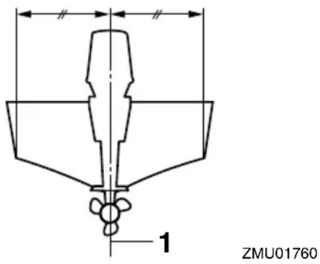
- Center line (keel line)
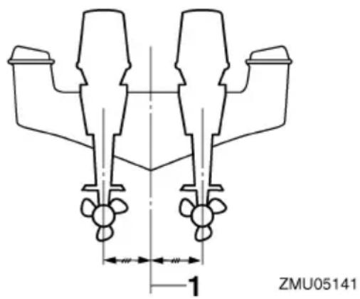
- Center line (keel line)
EMU26934
Mounting height (boat bottom)
The mounting height of your outboard motor affects its efficiency and reliability. If it is mounted too high, propeller ventilation may occur, which will reduce propulsion due to excessive propeller slip, and the water intakes for the cooling system may not get adequate water supply, which can cause engine overheating. If the engine is mounted too low, water resistance (drag) will increase, thereby reducing engine efficiency and performance.
Most commonly, outboard motor should be mounted so that the anti-cavitation plate is in alignment with the bottom of the boat. The optimum mounting height of the outboard
motor is affected by the boat/motor combination and the desired use. Test runs at different heights can help determine the optimum mounting height. Consult your Yamaha dealer or boat manufacturer for further information on determining the proper mounting height.
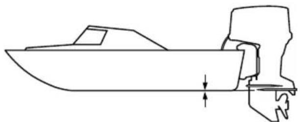
natural_image
Line drawing of a boat with a side-mounted mast and side-mounted gear (no text or symbols)ZMU01762
ECM01634
NOTICE
- Make sure that the idle hole is high enough to prevent water from entering the engine even if the boat is stationary with the maximum load.
- Incorrect engine height or obstructions to the smooth flow of water (such as the design or condition of the boat, or accessories, such as transom ladders or depth finder transducers) can create airborne water spray while the boat is cruising. If the outboard motor is operated continuously in the presence of airborne water spray, enough water could enter the engine through the air intake opening in the top cowling to cause severe engine damage. Remove the cause of the airborne water spray.
EMU36381
First-time operation
EMU40510
Filling engine oil
The outboard motor is shipped from the factory without engine oil. If your Yamaha dealer did not fill the engine with engine oil, you must fill the engine before starting it. NOTICE: Make sure that the engine is filled with engine oil before operating the outboard motor for the first time. Otherwise, the engine could be damaged severely. [ECM02240]
The following sticker, which is affixed to the outboard motor when it is shipped from the factory, should be removed after the engine is filled with engine oil for the first time. For more information on checking the engine oil level, see page 54.
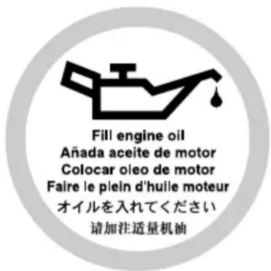
ZMU01710
EMU30174
Breaking in engine
Your new engine requires a period of break-in to allow mating surfaces of moving parts to wear in evenly. Correct break-in will help ensure proper performance and longer engine life. NOTICE: Failure to follow the break-in procedure could result in reduced engine life or even severe engine damage. [ECM00801]
EMU41222
Procedure for breaking in engine
Your new engine requires a period of 10 hours break-in so that mating surfaces of moving parts wear in evenly.
Operate the engine in the water under load (in gear with a propeller installed) for 10 hours as follows. When breaking in the engine, avoid extended idling, rough water, and crowded areas.
- For the 1st hour of operation:
Operate the engine at varying speeds up to 2000 r/min or approximately 1/2 throttle. - For the 2nd hour of operation:
Increase the engine speed until the boat is on plane (but avoid full-throttle operation), and then back off on the throttle while keeping the boat at a planing speed. - For the remaining 8 hours of operation:
Operate the engine at any speed. However, avoid operating at full throttle for more than 5 minutes at a time. - After the 1st 10 hours of operation:
Operate the engine normally.
EMU36400
Getting to know your boat
Different boats handle differently. Operate cautiously while you learn how your boat handles under different conditions and with different trim angles (see page 64).
EMU36413
Checks before starting engine
EWM01921

If any item in “Checks before starting engine” is not working properly, have it inspected and repaired before operating the outboard motor. Otherwise, an accident could occur.
ECM00120
NOTICE
Do not start the engine out of water. Overheating and serious engine damage can
occur.
EMU36421
Fuel level
Be sure you have plenty of fuel for your trip. A good rule is to use 1/3 of your fuel to get to the destination, 1/3 to return, and to keep 1/3 as an emergency reserve. With the boat level on a trailer or in the water, turn the key to "ON(on) and check the fuel level. For fuel filling instructions, see page 58.
EMU40770
Removing top cowling
For the following checks, remove the top cowling from the bottom cowling.
To remove the top cowling, pull the cowling lock levers and lift up the top cowling.
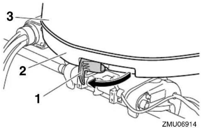
- Cowling lock lever
- Bottom cowling
- Top cowling
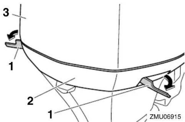
-
Cowling lock lever(s)
-
Bottom cowling
- Top cowling
EMU36442
Fuel system
EWM00060

WARNING
Gasoline and its vapors are highly flammable and explosive. Keep away from sparks, cigarettes, flames, or other sources of ignition.
EWM00910

WARNING
Leaking fuel can result in fire or explosion.
- Check for fuel leakage regularly.
- If any fuel leakage is found, the fuel system must be repaired by a qualified mechanic. Improper repairs can make the outboard unsafe to operate.
EMU36451
Check for fuel leaks
- Check for fuel leaks or gasoline fumes in the boat.
- Check for fuel leakage from the fuel system.
- Check the fuel tank and fuel lines for cracks, swellings, or other damages.
EMU37322
Checking the fuel filter
Check that the fuel filter is clean and free of water. If any water is found in the fuel, or if a significant amount of debris is found, the fuel tank should be checked and cleaned by a Yamaha dealer.
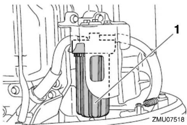
- Fuel filter
EMU41770
Controls
- Turn the main switch ON (on) and make sure that the Digital electronic control-active indicator comes on.
- Turn the steering wheel full-right and full-left. Make sure operation is smooth and unrestricted throughout the whole range with no binding or excessive free play.
- Operate the throttle levers several times to make sure there is no hesitation in their travel. Operation should be smooth over the complete range of motion, and each lever should return completely to the idle position.
EMU40362
Engine shut-off cord (lanyard)
Check the engine shut-off cord and clip for damage, such as cuts, breaks, and wear.
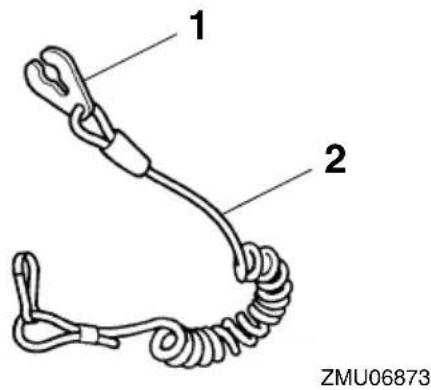
- Clip
- Engine shut-off cord (lanyard)
EMU40993
Engine oil
-
Place the outboard motor in a vertical position (not tilted). NOTICE: If the outboard motor is not level, the oil level indicated on the oil dipstick may not be accurate. [ECM01861]
-
Remove the oil dipstick and wipe it clean.
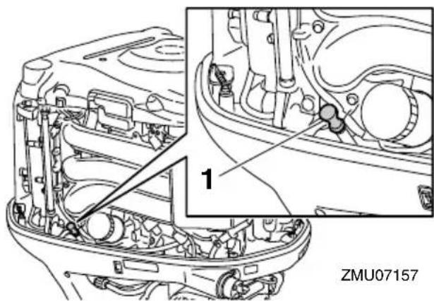
-
Oil dipstick
-
Insert the oil dipstick completely and remove it again.
-
Check that the oil level on the oil dipstick is between the upper and lower marks. Consult your Yamaha dealer if the oil level is not at the proper level or if it appears milky or dirty.

- Oil dipstick
- Upper mark
- Lower mark
EMU40411
Outboard motor
- Check that the outboard motor is mounted properly and check the outboard motor mounting bolts for looseness.
- Check the propeller for damage.
- Check for engine oil leaks.
EMU40371
Flushing device
Check that the flushing device is securely tightened on to the fitting on the bottom cowling. NOTICE: Make sure to connect the garden hose connector to the fitting on the bottom cowling and tighten it securely. Otherwise, cooling water will leak out during operation, causing the engine to overheat. [ECM02291]
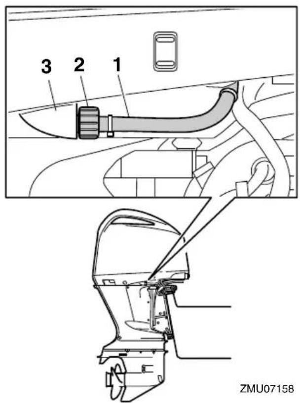
- Flushing device
- Garden hose connector
- Fitting
EMU40751
Installing top cowling
- Check the rubber seal for damage. If the rubber seal is damaged, have it replaced by a Yamaha dealer.
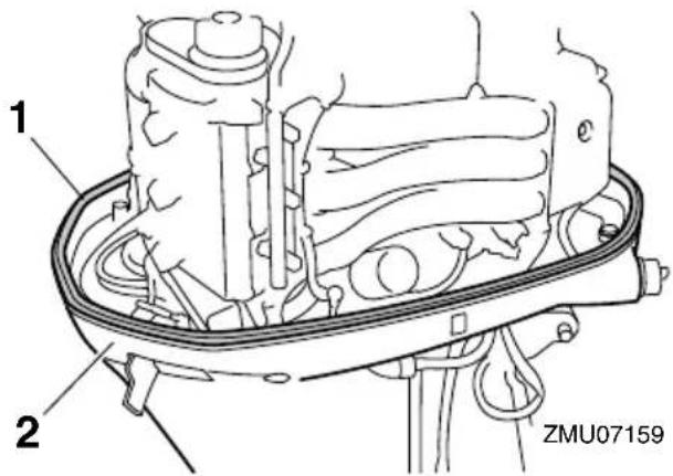
- Rubber seal
-
Bottom cowling
-
Check that the rubber seal is seated all the way around the bottom cowling.
- Check that all of the cowling lock levers are pulled outward.
- Align the 3 protrusions on the top cowling with the corresponding holders on the bottom cowling, and then place the top cowling on the bottom cowling.
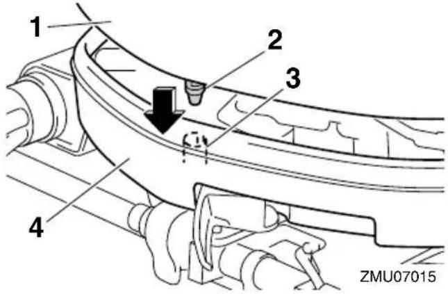
- Top cowling
- Protrusion
- Holder
- Bottom cowling
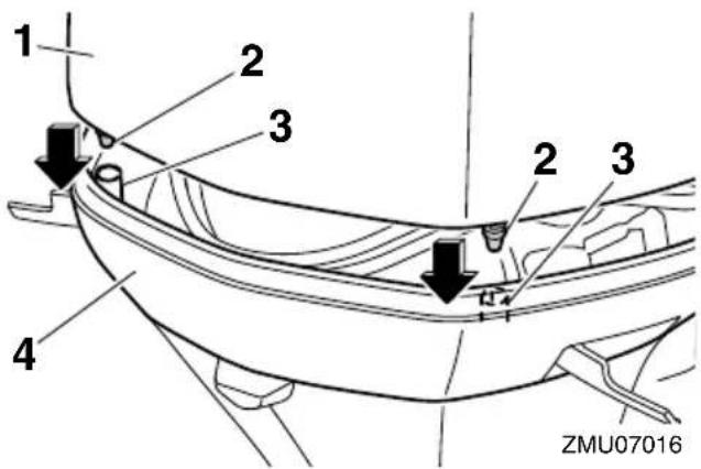
- Top cowling
- Protrusion
- Holder
-
Bottom cowling
-
Push the cowling lock levers inward to secure the top cowling.
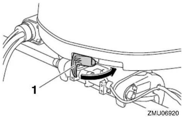
- Cowling lock lever
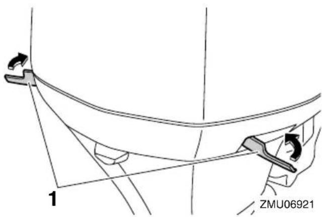
-
Cowling lock lever(s)
-
Check the fitting of the top cowling by pushing it with both hands. NOTICE: If the top cowling is not installed correctly, water can enter the top cowling and damage the engine, or the top cowling can blow off at high speeds.
[ECM02370]
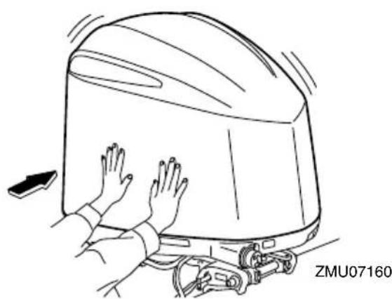
natural_image
Line drawing of a person pushing a large vehicle with hands, no text or symbols presentEMU35243
Checking power trim and tilt system
EWM01930
WARNING
- Never get under the lower unit while it is tilted, even when the tilt support lever is locked. Severe injury could occur if the outboard motor accidentally falls.
- Body parts can be crushed between the motor and the clamp bracket when the motor is trimmed or tilted.
-
Be sure no one is near the outboard motor before performing this check.
-
Check the power trim and tilt unit for any sign of oil leaks.
- Operate each of the power trim and tilt switches on the digital electronic control and engine bottom cowling (if equipped) to check that all switches work.
- Tilt the outboard motor up and check that the tilt rod and trim rods are extended completely.
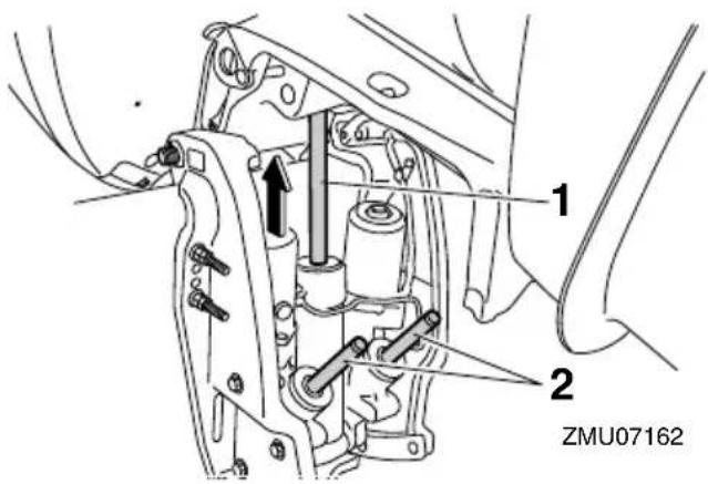
- Tilt rod
-
Trim rods
-
Use the tilt support lever to lock the motor in the up position. Operate the tilt down switch briefly so the motor is supported by the tilt support lever.

natural_image
Technical line drawing of a mechanical assembly with labeled component (no readable text or symbols)-
Tilt support lever
-
Check that the tilt rod and trim rods are free of corrosion or other flaws.
- Activate the tilt-down switch until the trim rods have retracted completely into the cylinders.
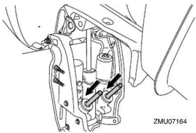
natural_image
Mechanical assembly diagram showing internal components with arrows indicating movement or force (no text or symbols)- Activate the trim-up switch until the tilt rod is fully extended. Unlock the tilt support lever.
- Tilt the outboard motor down. Check that the tilt rod and trim rods operate smoothly.
EMU36582
Battery
Check that the battery is in good condition, and fully charged. Check that the battery connections are clean, secure and covered by insulating covers. The electrical contacts of the battery and cables must be clean and properly connected or the battery will not
start the engine.
Refer to the battery manufacturer's instructions for checks for your particular battery.
EMU30026
Filling fuel
EWM01830

WARNING
- Gasoline and its vapors are highly flammable and explosive. Always refuel according to this procedure to reduce the risk of fire and explosion.
-
Gasoline is poisonous and can cause injury or death. Handle gasoline with care. Never siphon gasoline by mouth. If you should swallow some gasoline or inhale a lot of gasoline vapor, or get some gasoline in your eyes, see your doctor immediately. If gasoline spills on your skin, wash with soap and water. If gasoline spills on your clothing, change your clothes.
-
Make sure that the engine is stopped.
- Make sure that the boat is in a well-ventilated outdoor area, either securely moored or trailered.
- Make sure that no one is in the boat.
- Do not smoke and keep away from sparks, flames, static electric discharge, or other sources of ignition.
- If you use a portable container to store and dispense fuel, only use a locally approved GASOLINE container.
- Touch the fuel nozzle to the filler opening or funnel to help prevent electrostatic sparks.
-
Fill the fuel tank, but do not overfill. WARNING! Do not overfill. Otherwise fuel can expand and overflow if the temperature increases. [EWM02610]
-
Tighten the fuel tank cap securely.
-
Wipe up any spilled gasoline immediate-
ly with dry rags. Dispose of rags properly according to local laws or regulations.
EMU40251
Operating engine
EWM02600

WARNING
This product emits exhaust gases which contain carbon monoxide, a colorless, odorless gas which could cause brain damage or death when inhaled. Symptoms include nausea, dizziness, and drowsiness. Keep cockpit and cabin areas well ventilated. Avoid blocking exhaust outlets.
EMU41290
Sending fuel
- If your boat is equipped with a fuel tank selector valve, turn the valve to select the appropriate fuel tank.
- Squeeze the primer pump, with the arrow pointing up, until you feel it become firm.
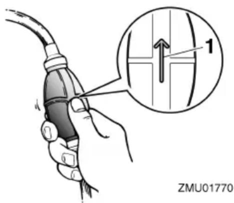
- Arrow
EMU27494
Starting engine
EWM01600

WARNING
Before starting the engine, make sure that the boat is tightly moored and that you can steer clear of any obstructions.
Be sure there are no swimmers in the water near you.
EMU41790
Start-up checks
Place the control lever in neutral and turn the main switch to "ON(on). Make sure that no alert-indicator comes on. If the buzzer sounds and the water separator-alert indicator blinks, consult your Yamaha dealer immediately.
EMU41901
Procedure for starting engine
EWM01840
WARNING
- Failure to attached engine shut-off cord could result in a runaway boat if operator is ejected. Attach the engine shut-off cord to a secure place on your clothing, or your arm or leg while operating. Do not attach the cord to clothing that could tear loose. Do not route the cord where it could become entangled, preventing it from functioning.
-
Avoid accidentally pulling the cord during normal operation. Loss of engine power means the loss of most steering control. Also, without engine power, the boat could slow rapidly. This could cause people and objects in the boat to be thrown forward.
-
Place the control lever in neutral.
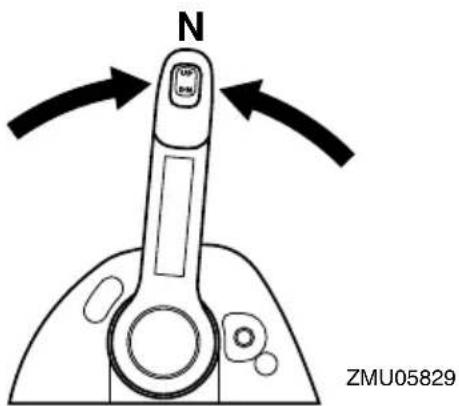
TIP:
The start-in-gear protection device prevents the engine from starting except when in neutral.
- Attach the engine shut-off cord to a secure place on your clothing, or your arm or leg. Then install the clip on the other end of the cord into the engine shut-off switch.
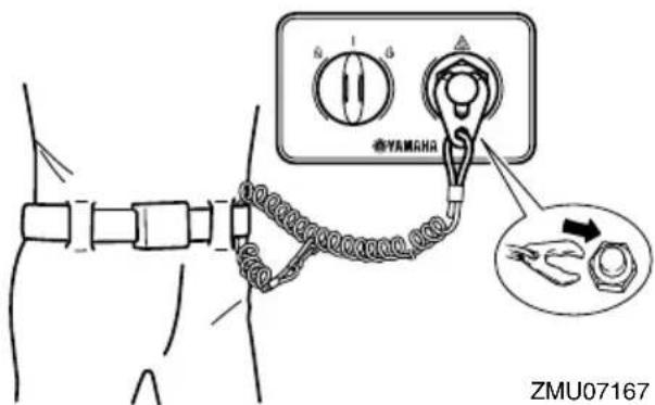
- Turn the main switch to “ON(on) to make sure that the digital electronic control-active indicator lights. The engine can not be started when the digital electronic control-alert indicator lights.
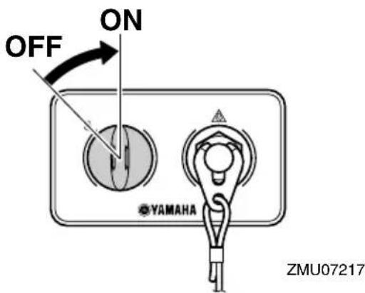
- Turn the main switch to “”(start), and hold it for a maximum of 5 seconds. NOTICE: Never turn the main switch to “ST(Astart) while the engine is running. Do not keep the starter motor turning for more than 5 seconds. If the starter motor is turned continu-
ously for more than 5 seconds, the battery will be quickly discharged, thus making it impossible to start the engine. The starter can also be damaged. If the engine will not start after 5 seconds of cranking, return the main switch to “ON(on), wait 10 seconds, then crank the engine again.
[ECM00192]
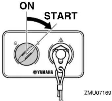
When starting the engine using the Start/Stop button, press the button to start the engine. The indicator for the starting engine will come on.
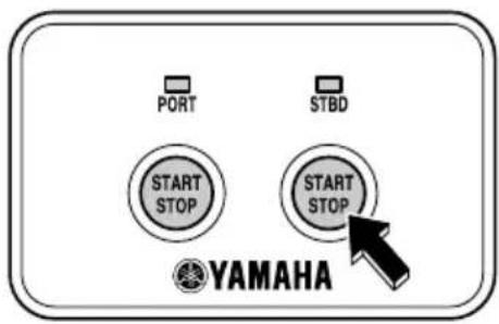
ZMU07148
When starting the engine using the Start/Stop button on the All Start/Stop switch panel, press the button to start the all engines.

ZMU07150
TIP:
- When the main switch is turned to START (start) with the clip removed from the engine shut-off switch, the buzzer will sound.
- For twin type, if the clip is removed from the engine shut-off switch, the buzzer will sound when the Start/Stop button is pressed.
- For twin type, when either engine has started, the engine that has started can be stopped by pressing the Start/Stop button on the All Start/Stop switch panel.
EMU36510
Checks after starting engine
EMU41360
Cooling water
Check for a steady flow of water from the cooling water pilot hole. A continuous flow of water from the cooling water pilot hole shows that the water pump is pumping water through the cooling water passages.
TIP:
When the engine is started, there may be a slight delay before water flows from the cooling water pilot hole.
ECM02250
NOTICE
If water is not flowing out of the cooling water pilot hole at all times while the engine is running, overheating and serious damage could occur. Stop the engine and
check whether the cooling water inlet on the lower case or the cooling water pilot hole is blocked. Consult your Yamaha dealer if the problem cannot be located and corrected.
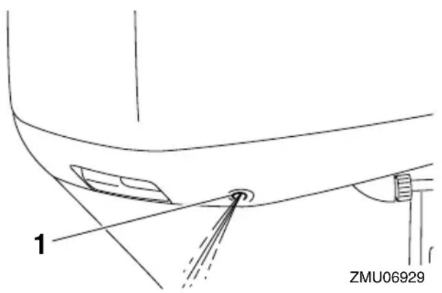
natural_image
Technical line drawing of a mechanical component with labeled parts (no readable text or symbols)- Cooling water pilot hole
EMU27670
Warming up engine
EMU41810
Electric start models
After the engine has started, warm up the engine until the engine speed settles at idling speed. The engine warming-up indicator is shown on the Multi-Display while the engine warms up. For further information, see page 36.
EMU36531
Checks after engine warm up
EMU36541
Shifting
While the boat is tightly moored, and without applying throttle, confirm that the engine shifts smoothly into forward and reverse, and back to neutral.
EMU41820
Stop switches
Perform the following procedure to check that the main switch and engine shut-off switch operate properly.
- Check that the engine stops when the main switch is turned to the "OFF" po-
sition, or press the Start/Stop button.
- Check that the engine stops when the clip is pulled from the engine shut-off switch.
- Check that the engine cannot be started with the clip removed from the engine shut-off switch.
EMU35124
Shifting
EWM00180
! WARNING
Before shifting, make sure there are no swimmers or obstacles in the water near you.
Warm up the engine before shifting into gear. Until the engine is warm, the idle speed may be higher than normal. The control lever of the Digital electronic control can be operated even at high engine speeds. However, gear shifting will not work until the engine speed has automatically decreased to a speed at which actual gear shifting is possible. As a result, for quick gear shifting there could be a time lag when the gear is shifted until the engine speed has decreased sufficiently.
To shift out of neutral
- Pull the neutral interlock trigger up (if equipped).
- Move the control lever firmly and crisply forward (for forward gear) or backward (for reverse gear) 22.5^ (a detent can felt).
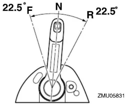
To shift from in gear (forward/reverse) to neutral
- Close the throttle so that the engine slows to idle speed.
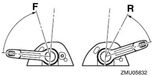
- After the engine is at idle speed in gear move the control lever firmly and crisply into the neutral position.

EMU31742
Stopping boat
EWM01510
WARNING
- Do not use the reverse function to slow down or stop the boat as it could cause you to lose control, be ejected, or impact the steering wheel or other parts of the boat. This could increase the risk of serious injury. It could also damage the shift mechanism.
- Do not shift into reverse while traveling at planing speeds. Loss of control, boat swamping, or damage to the boat could
occur.
The boat is not equipped with a separate braking system. Water resistance stops it after the throttle lever is moved back to idle. The stopping distance varies depending on gross weight, water surface conditions, and wind direction.
EMU30880
Trolling
EMU41831
Adjusting trolling speed
When the control lever is either in the forward position or in the reverse position and the throttle is in the fully closed position, you can randomly adjust the trolling speed between 600 r/min and 1000 r/min by increasing or decreasing it approximately by 50 r/min. The display will show the engine speed when the engine speed is increased from the fully closed position during trolling speed setting mode. When the throttle is returned to the fully closed position, the display will show the trolling speed again. When the engine is turned off or when the engine speed exceeds 3000 r/min, trolling speed setting mode will be released.
For details, see the attached operation manual.
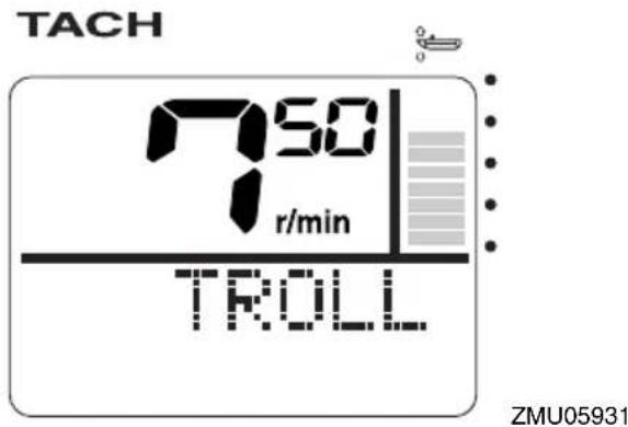
TACH
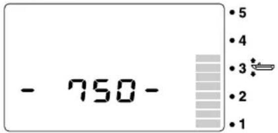
ZMU06309
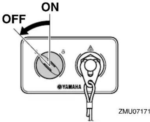
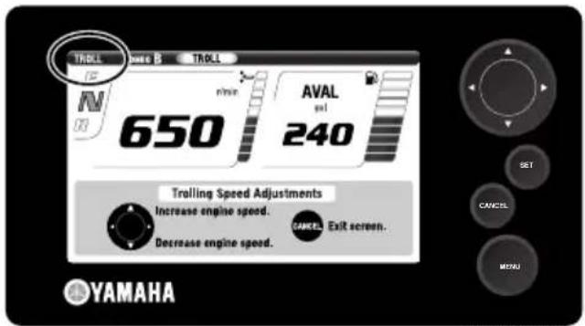
ZMU07256
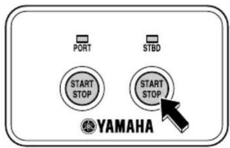
ZMU07148
TIP:
- Trolling is affected by currents and other operating conditions and may differ from the actual engine speed.
- When warming up a cold engine, the trolling speed cannot be decreased below the specified engine idle speed.
EMU27821
Stopping engine
Before stopping the engine, first let it cool off for a few minutes at idle or low speed. Stopping the engine immediately after operating at high speed is not recommended.
EMU41911
Procedure for stopping engine
- The engine can be turned off either by pressing the Start/Stop button or by turning the main switch to the "OR(Off) position. After the engine has been turned off using the Start/Stop button, turn the main switch to the "OR(Off) position.
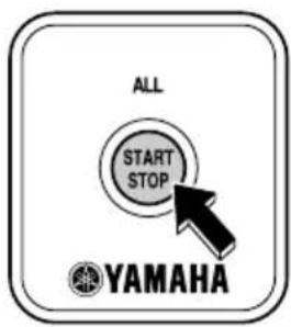
ZMU07150
TIP:
- The engine can also be stopped by pulling the cord and removing the clip from the engine shut-off switch, then turning the main switch to "OFF".
- Remove the key if the boat will be left un-attended.
EMU27862
Trimming outboard motor
EWM00740
WARNING
Excessive trim for the operating conditions (either trim up or trim down) can cause boat instability and can make steering the boat more difficult. This increases the possibility of an accident. If the boat begins to feel unstable or is hard to steer, slow down and/or readjust the trim angle.
The trim angle of the outboard motor helps determine the position of the bow of the boat in the water. Correct trim angle will help improve performance and fuel economy while reducing strain on the engine. Correct trim angle depends upon the combination of boat, engine, and propeller. Correct trim is also affected by variables such as the load in the boat, sea conditions, and running speed.

- Trim operating angle
EMU27888
Adjusting trim angle (Power trim and tilt)
EWM00753
WARNING
- Be sure all people are clear of the outboard motor when adjusting the trim angle. Body parts can be crushed be-
tween the motor and the clamp bracket when the motor is trimmed or tilted.
- Use caution when trying a trim position for the first time. Increase speed gradually and watch for any signs of instability or control problems. Improper trim angle can cause loss of control.
- If equipped with a power trim and tilt switch located on the bottom cowling, use the switch only when the boat is at a complete stop with the engine off. Do not adjust the trim angle with this switch while the boat is moving.
Adjust the outboard motor trim angle using the power trim and tilt switch.
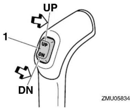
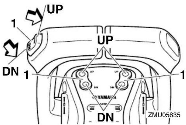
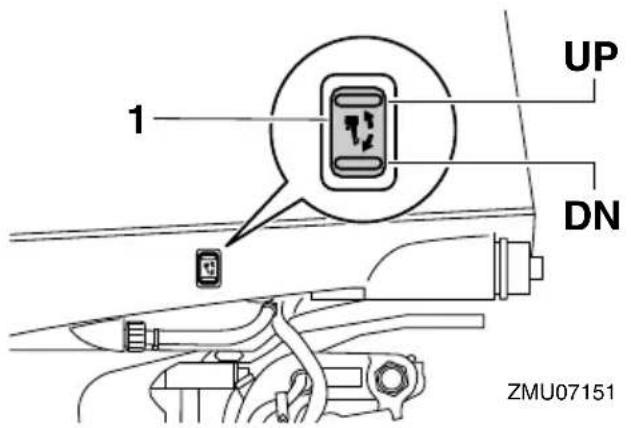
- Power trim and tilt switch
To raise the bow (trim-out), press the switch "URup).
To lower the bow (trim-in), press the switch "DNdown).
Make test runs with the trim set to different angles to find the position that works best for your boat and operating conditions.
EMU27912
Adjusting boat trim
When the boat is on plane, a bow-up attitude results in less drag, greater stability and efficiency. This is generally when the keel line of the boat is up about 3 to 5 degrees. With the bow up, the boat may have a greater tendency to steer to one side or the other. Compensate for this as you steer. When the bow of the boat is down, it is easier to accelerate from a standing start onto plane.
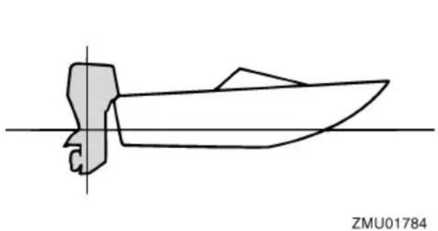
natural_image
Pure technical line drawing of a boat or vessel without any text, numbers, or symbolsBow Up
Too much trim-out puts the bow of the boat too high in the water. Performance and economy are decreased because the hull of the boat is pushing the water and there is more air drag. Excessive trim-out can also cause the propeller to ventilate, which reduces performance further, and the boat may “porpoise” (hop in the water), which could throw the operator and passengers overboard.
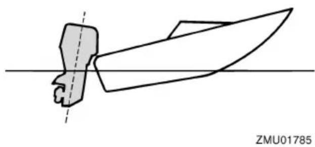
natural_image
Pure technical line drawing of a mechanical component without any text or symbolsBow Down
Too much trim-in causes the boat to "plow" through the water, decreasing fuel economy and making it hard to increase speed. Operating with excessive trim-in at higher speeds also makes the boat unstable. Resistance at the bow is greatly increased, heightening the danger of "bow steering" and making operation difficult and dangerous.
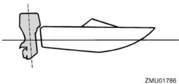
natural_image
Simple line drawing of a boat with a side arm and hull, no text or symbols presentTIP:
Depending on the type of boat, the outboard
motor trim angle may have little effect on the trim of the boat when operating.
EMU27946
Tilting up and down
If the engine will be stopped for some time or if the boat is moored in shallows, the outboard motor should be tilted up to protect the propeller and lower case from damage by collision with obstructions, and also to reduce salt corrosion.
EWM01543

WARNING
Make sure that all people are clear of the outboard motor when tilting the outboard motor up and down. Body parts can be crushed between the outboard motor and the clamp bracket when the outboard motor is trimmed or tilted.
ECM00991
NOTICE
- Before tilting the outboard motor, follow the procedure under “Stopping engine” in this chapter. Never tilt the outboard motor while the engine is running. Severe damage from overheating can result.
- To prevent the cooling water passages from becoming frozen when the ambient temperature is 5°C or below, tilt the outboard motor up after it has been stopped 30 seconds or more.
EMU35509
Procedure for tilting up (power trim and tilt models)
- Place the control lever in neutral.

- Press the power trim and tilt switch “”UP (up) until the outboard motor has tilted up completely.
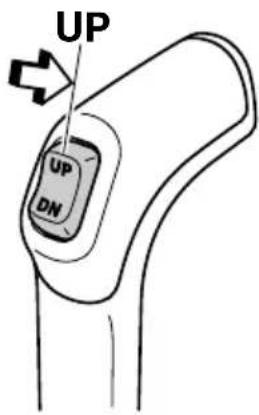
ZMU05837
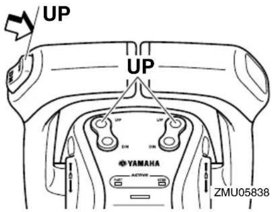

- Set the tilt support lever to support the engine. WARNING! After tilting the outboard motor, be sure to support it with the tilt support knob or tilt support lever. Otherwise the outboard motor could fall back down suddenly if oil in the power trim and tilt unit or in the power tilt unit loses pressure. [EWM00262] NOTICE: Do not use the tilt support lever or knob when trailering the boat. The outboard motor could shake loose from the tilt support and fall. If the motor cannot be trailed in the normal running position, use an additional support device to secure it in the tilt position. For more detailed information, see page 70. [ECM01641]
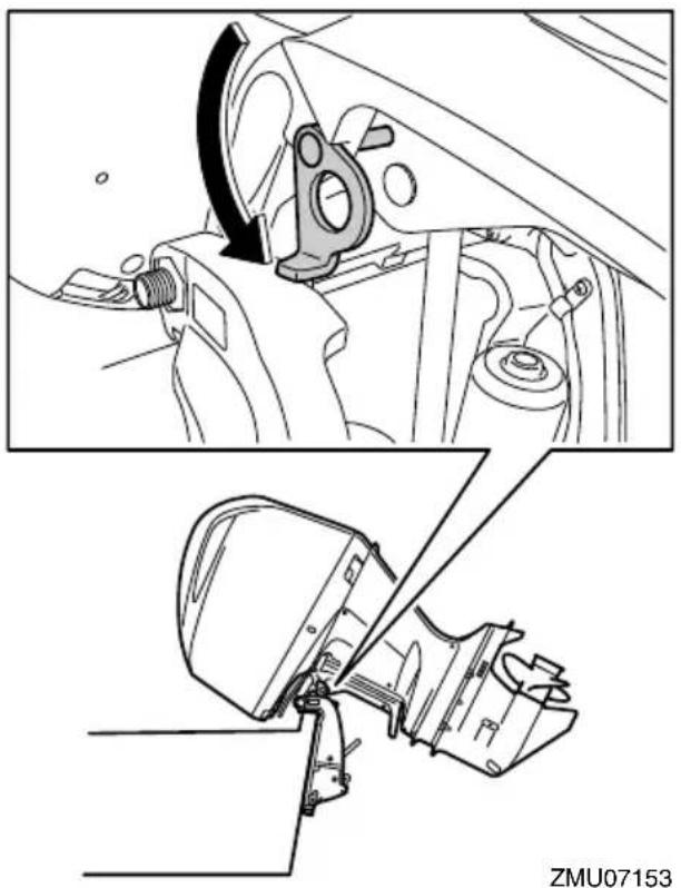
natural_image
Technical diagram showing mechanical assembly steps with no visible text or symbols- Once the outboard motor is supported with the tilt support lever, press the power trim and tilt switch "DN(down) to retract the trim rods. NOTICE: Make sure that the trim rods retracts completely during mooring. This protects the rods from marine growth and corrosion, which could damage the power trim and tilt mechanism. [ECM00252]
EMU35516
Procedure for tilting down (power trim and tilt models)
-
Push the power trim and tilt switch “”UP (up) until the outboard motor is supported by the tilt rod and the tilt support lever becomes free.
-
Release the tilt support lever.
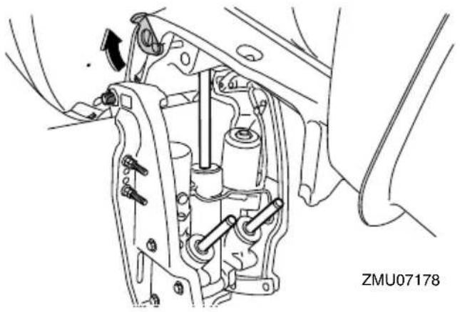
natural_image
Mechanical assembly diagram showing internal components and a directional arrow (no text or symbols)- Push the power trim and tilt switch “”DN (down) to lower the outboard motor to the desired position.
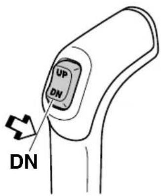
ZMU05840
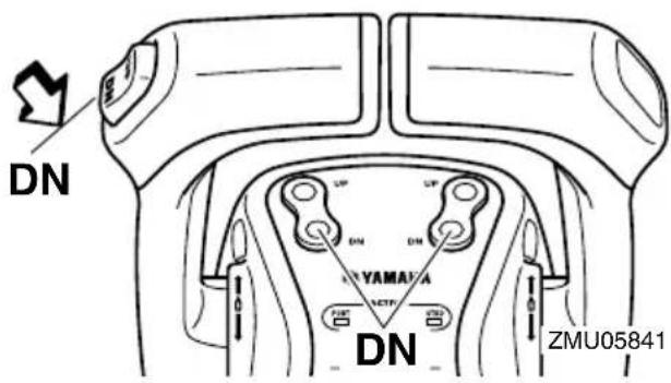
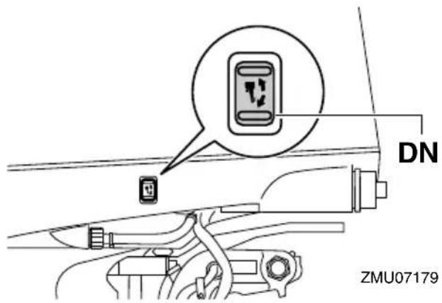
EMU28062
Shallow water
EMU40701
Cruising in shallow water
The outboard motor can be tilted up partially to allow operation in shallow water.
ECM02360
NOTICE
Do not tilt the outboard motor up so that the cooling water inlet on the lower unit is above the surface of the water when setting up for and cruising in shallow water. Otherwise severe damage from overheating can result.
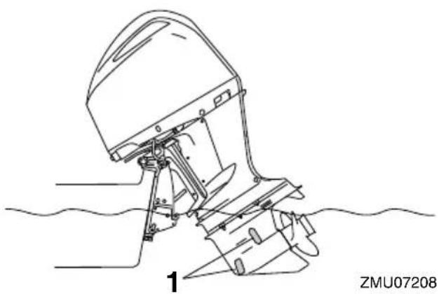
natural_image
Technical line drawing of a boat's side-mounted motor with levers and suspension components (no text or symbols)- Cooling water inlet
EMU35236
Procedure for power trim and tilt models
- Place the control lever in neutral.
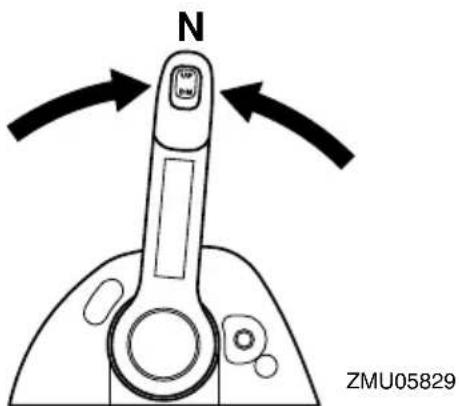
- Slightly tilt the outboard motor up to the desired position using the power trim and tilt switch. WARNING! Using the power trim and tilt switch on the bottom cowling while the boat is moving or engine is on could increase the risk of falling overboard and could distract the operator, increasing the risk of collision with another boat or an obstacle. [EWM01850]
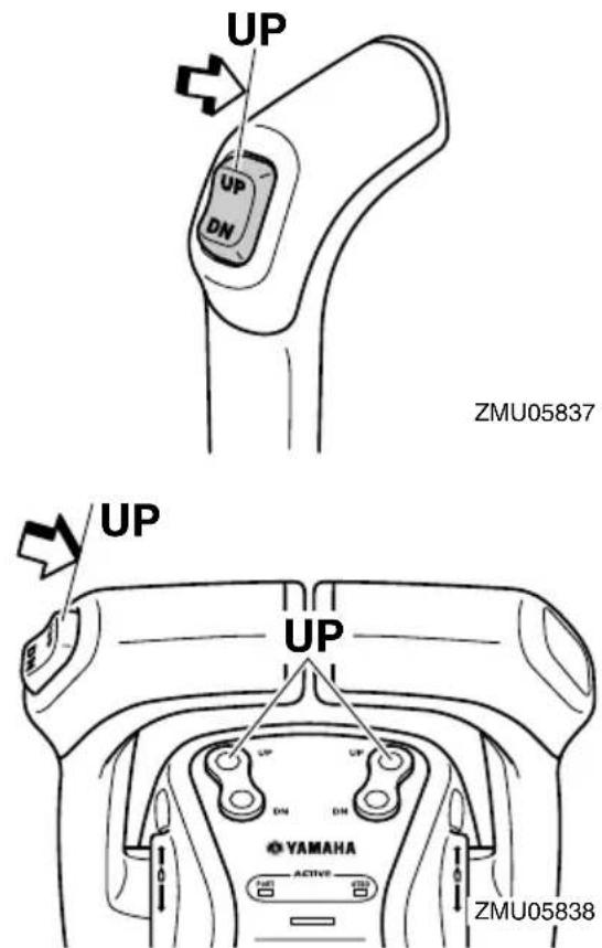
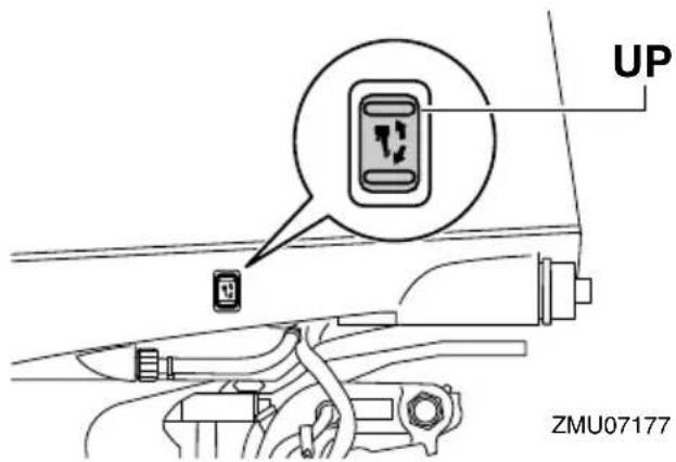
- To return the outboard motor to the normal running position, press the power trim and tilt switch and slowly tilt the outboard motor down.
EMU41370
Operating in other conditions
Operating in salt water
After operating in saltwater, brackish water, or water high in other minerals, flush the cooling system with fresh water to minimize corrosion and clogging of the cooling water passages with deposits. Also, rinse the exterior of the outboard motor with fresh water.
Operating in water containing mud, sand, silt, debris, or vegetation
Mud, sand, silt, debris, and vegetation in the water may restrict water flow into the cooling water inlet covers or clog internal water passages. Check and clean the cooling water inlet covers frequently when operating in these conditions. Flush the engine with clean, fresh water after use in these environments. Consult your dealer if normal water flow can not be restored by cleaning the cooling water inlet covers or flushing with fresh water.
EMU41531
Transporting and storing outboard motor
EWM02640
WARNING
- USE CARE when transporting fuel tank, whether in a boat or car.
- DO NOT fill fuel container to maximum capacity. Gasoline will expand considerably as it warms up and can build up pressure in the fuel container. This can cause fuel leakage and a potential fire hazard.
- Leaking fuel is a fire hazard. Tighten securely the fuel valve when transporting and storing the outboard motor.
- Never get under the outboard motor while it is tilted. Severe injury could occur if the outboard motor accidentally falls.
- Do not use the tilt support lever or knob when trailering the boat. The outboard motor could shake loose from the tilt support and fall. If the outboard motor cannot be trailed in the normal running position, use an additional support device to secure it in the tilt position.
Leaking fuel is a fire hazard. When trailering the boat, close the fuel valve to prevent fuel from leaking.
The outboard motor should be transported and stored in the normal running position. If there is insufficient road clearance in this position, then trailer the outboard motor in the tilt position using a motor support device such as a transom saver bar. Consult your Yamaha dealer for further details.
When the outboard motor is tilted prolonged time for mooring or trailering the boat, close the fuel valve.
EMU35411
Storing outboard motor
When storing your Yamaha outboard motor for prolonged periods of time (2 months or longer), several important procedures must be performed to prevent excessive damage. It is advisable to have your outboard motor serviced by an authorized Yamaha dealer prior to storage. However, you, the owner, with a minimum of tools, can perform the following procedures.
ECM01720
NOTICE
Store the outboard motor in a dry, well-ventilated place, not in direct sunlight.
Keep the outboard motor in the attitude shown when transporting and storing it.
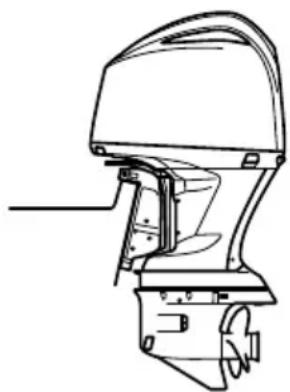
natural_image
Technical line drawing of a boat hull with no text or symbolsZMU05843
EMU41380
Conditioning and stabilizing gasoline
When preparing to store a boat for extended periods (2 months or longer) it is best to completely remove all gasoline from the boat's fuel tank(s). If it is not possible to remove the gasoline, add one ounce of "Yamalube Fuel Stabilizer & Conditioner Plus" to each gallon of gasoline in a full tank of gasoline to provide fuel stability and corrosion protection.
TIP:
Do not fill the fuel tank(s) to the point of overflowing. Approximately 7/8 full will allow enough space in the fuel tank to prevent gas-
oline purging from the fuel tank vent due to expansion with temperature changes.
Do not cap the fuel tank vent. Excessive pressure could damage the boat and motor's fuel systems.
A partially filled fuel tank, less than 7/8 full but not completely empty, is not recommended. Air space above the gasoline allows air movement which can bring in water through condensation as the air temperature changes.
Condensation inside the fuel tank can cause corrosion problems and phase separation of gasoline containing ethanol.
Consult your Yamaha dealer concerning preventative measures that may work best for the gasoline and environmental conditions in your area.
EMU28305
Procedure
EMU41141
Cleaning the outboard motor
When cleaning the outboard motor, the top cowling must be installed.
- Wash the exterior of the outboard motor using fresh water. NOTICE: Do not spray water into the air intake. [ECM01840]
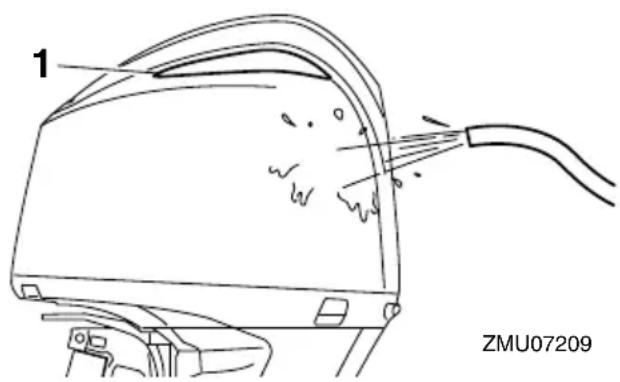
-
Air intake
-
Drain the cooling water completely out of the outboard motor. Clean the body thoroughly.
EMU41071
Lubrication
- Change the gear oil. For instructions, see page 88. Check the gear oil for the presence of water that indicates a leaky seal. Seal replacement should be performed by an authorized Yamaha dealer prior to use.
- Lubricate all grease fittings. For further details, see page 77.
TIP:
For long-term storage, fogging the engine with fogging oil is recommended. Contact your Yamaha dealer for information about fogging oil and procedures for your outboard motor.
EMU41152
Cleaning and anticorrosion measures
- Wash the exterior of the outboard motor using fresh water, and then dry the outboard motor completely. For instructions on cleaning the outboard motor, see page 71. NOTICE: Do not spray water into the air intake. [ECM01840]
- Spray the outboard motor powerhead with "Yamaha Silicone Protectant."
- Wax the cowling with a non-abrasive wax such as "Yamaha Silicone Wax."
EMU40962
Flushing cooling water passage
Perform this procedure right after operation for the most thorough flushing.
ECM01530
NOTICE
Do not perform this procedure while the engine is running. The water pump may be damaged and severe damage from overheating can result.
- Disconnect the garden hose connector from the fitting on the bottom cowling.
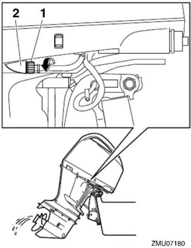
- Garden hose connector
-
Fitting
-
Connect the garden hose to the garden hose connector.
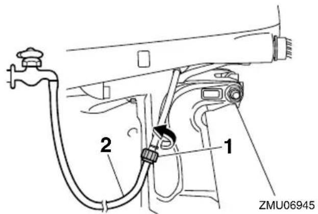
- Garden hose connector
-
Garden hose
-
With the engine off, turn on the water supply and let the water flush through the cooling water passages for about 15 minutes.
-
Turn off the water supply, and then disconnect the garden hose from the garden hose connector.
- Connect the garden hose connector to the fitting on the bottom cowling and tighten it securely. NOTICE: If the garden hose connector is not properly connected, cooling water can leak out and the engine can overheat during operation. [ECM01801]
TIP:
When flushing the cooling water passages with the boat in the water, tilting the outboard motor up until it is completely out of the water will achieve better results.
EMU28461
Checking painted surface of outboard motor
Check the outboard motor for scratches, nicks, or flaking paint. Areas with damaged paint are more likely to corrode. If necessary, clean and paint the areas. A touch-up paint is available from your Yamaha dealer.
EMU2848B
Periodic maintenance
EWM01871

WARNING
These procedures require mechanical skills, tools, and supplies. If you do not have the proper skills, tools, or supplies to perform a maintenance procedure, have a Yamaha dealer or other qualified mechanic do the work.
The procedures involve disassembling the motor and exposing dangerous parts. To reduce the risk of injury from moving, hot, or electrical parts:
- Turn off the engine and keep the key(s) and engine shut-off cord (lanyard) with you when you perform maintenance unless otherwise specified.
- The power trim and tilt switches operate even when the ignition key is off. Keep people away from the switches whenever working around the motor. When the motor is tilted, keep away from the area under it or between it and the clamp bracket. Be sure no one is in this area before operating the power trim and tilt mechanism.
- Allow the engine to cool before handling hot parts or fluids.
- Always completely reassemble the motor before operation.
Maintenance, replacement, or repair of the emission control devices and systems may be performed by any marine engine repair establishment or individual. All warranty repairs, however, including those to the emission control system, must be performed by an authorized Yamaha marine dealership.
A service manual is available for purchase through your Yamaha dealer for owners who have the mechanical skills, tools, and other equipment necessary to perform maintenance not covered by this owner's manual.
EMU28511
Replacement parts
If replacement parts are necessary, use only genuine Yamaha parts or parts of equivalent design and quality. Any part of inferior quality may malfunction, and the resulting loss of control could endanger the operator and passengers. Yamaha genuine parts and accessories are available from your Yamaha dealer.
EMU35521
Maintenance interval guidelines
The service intervals provided in the Maintenance Chart were developed based upon "typical" use that includes operating at varied speeds, with sufficient time for engine warm up and cool-down, a medium to light load, and an average cruising speed near the 3000 to 4000 rpm range. As with any engine, however, if your normal operating conditions are different, you should consider service more often than shown, especially how often you change your engine oil and gear oil. Examples might include extended wide-open-throttle use or long periods of trolling or idling, carrying heavy loads, or frequent starting and stopping or shifting. More frequent maintenance will often pay off many times over in increased engine life and greater owner satisfaction. Consult your Yamaha dealer for additional maintenance recommendations.
EMU34446
Maintenance chart 1
TIP:
- Refer to the sections in this chapter for explanations of each owner-specific action.
- The maintenance cycle on these charts assume usage of 100 hours per year and regular flushing of the cooling water passages. Maintenance frequency should be adjusted when operating the engine under adverse conditions such as extended trolling.
- Disassembly or repairs may be necessary depending on the outcome of maintenance checks.
- Expendable or consumable parts and lubricants will lose their effectiveness over time and through normal usage regardless of the warranty period.
- When operating in salt water, muddy, other turbid (cloudy), acidic water, the engine should be flushed with clean water after each use.
The “●” symbol indicates the check-ups which you may carry out yourself.
The “” symbol indicates work to be carried out by your Yamaha dealer.
| Item Actions | Initial Every | ||||
| 20 hours(3 months) | 100hours(1 year) | 300hours(3 years) | 500hours(5 years) | ||
| Anode(s) (external) | Inspection or replace-ment as necessary | ●/○ | |||
| Anode (cylinder head exhaust passage) | Inspection or replace-ment as necessary | ○ | |||
| Anodes (cylinder head, cylinder block, cylinder block thermostat por-tion, oil cooler cover, exhaust guide) | Replacement | ○ | |||
| Battery (electrolyte level, terminal) | Inspection | ●/○ | ●/○ | ||
| Battery (electrolyte level, terminal) | Fill, charging or replac-ing as necessary | ○ | |||
| Cooling water leakage | Inspection or replace-ment as necessary | ○ | ○ | ||
| Cowling lock lever Inspection | ●/○ | ||||
| Engine starting condi-tion/noise | Inspection | ●/○ | ●/○ | ||
| Engine idle speed/noise | Inspection | ●/○ | ●/○ | ||
| Engine oil Replacement | ●/○ | ●/○ | |||
| Engine oil filter (car-tridge) | Replacement | ○ | |||
| Fuel filter/water separator (can be disassembled) | Inspection or replacement as necessary |  |  | ||
| Fuel line (High pressure) | Inspection or replacement as necessary | [08DC] | [2DH] | ||
| Fuel line (Low pressure) | Inspection or replacement as necessary | [07DC] | [KAH] | ||
| Fuel pump | Inspection or replacement as necessary | [SBT] | |||
| Fuel/engine oil leakage | Inspection | [86DS] | [BCBT] | ||
| Gear oil Replacement | [11WVT] | [14DS] | |||
| Greasing points Greasing | [87DW] | [19SKT] | |||
| Impeller/water pump housing | Inspection or replacement as necessary | [22DD] | |||
| Impeller/water pump housing | Replacement | [08CA] | |||
| OCV (Oil Control Valve) filter | Replacement | [CBGA] | |||
| Power trim and tilt unit | Inspection | [4-HBS] | [06WT] | ||
| Propeller/propeller nut/cotter pin | Inspection or replacement as necessary | [12HC] | [16CX] | ||
| Spark plug(s) | Inspection or replacement as necessary | [WBSB] | |||
| Ignition coils/ignition coil leads | Inspection or replacement as necessary | [4KCT] | [19ZHW] | ||
| Water from the cooling water pilot hole | Inspection | [10HC] |  | ||
| Thermostat | Inspection or replacement as necessary | [22CH] | |||
| Timing belt | Inspection or replacement as necessary |  | |||
| Valve clearance | Inspection and adjustment | [08AC] | |||
| Cooling water inlet Inspection | [4A7W] | [18TD] | |||
| Main switch/stop switch | Inspection or replacement as necessary | [7BAC] | [20CD] | ||
| Wire harness connections/wire coupler connections | Inspection or replacement as necessary | [02DS] | [7BD4] | ||
| Connector connec-tions/lead connections | Inspection or replace-ment as necessary | ○ | ○ | ||
| (Yamaha) Meter/gauge | Inspection | ○ | ○ | ||
EMU34451
Maintenance chart 2
| Item Actions | Every | |
| 1000 hours | ||
| Exhaust guide/exhaust manifold | Inspection or replacement as necessary | ○ |
| Timing belt Replacement | ○ |
EMU41300
Greasing
Yamalube Marine Grease
F225, LF225, F250, LF250, F300, LF300, F250D1, FL250D1, F300B1, FL300B1
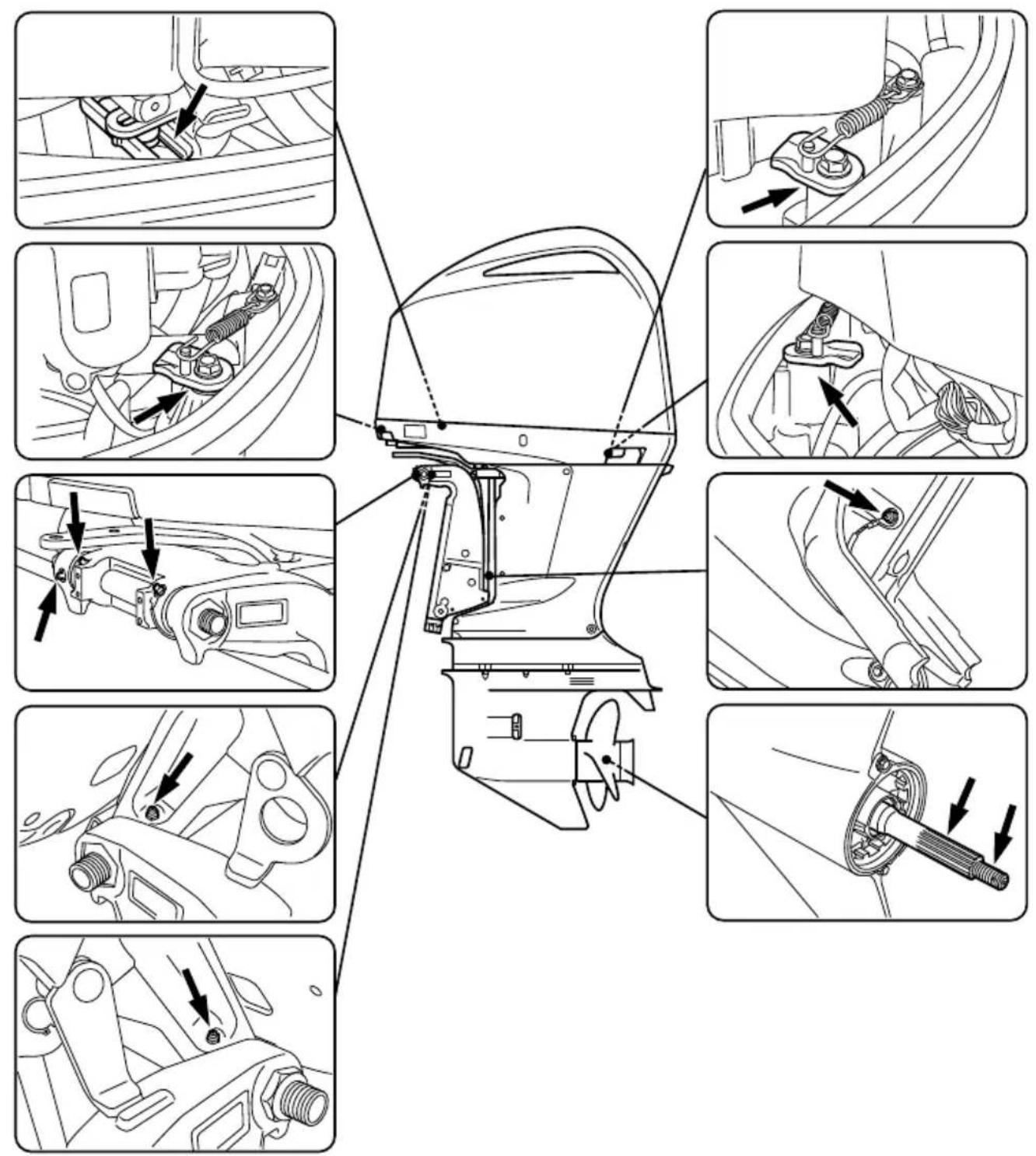
EMU40663
Inspecting spark plug
The spark plug is an important engine com-
ZMU07181
ponent. The condition of the spark plug can indicate something about the condition of the engine. For example, if the center electrode
porcelain is very white, this could indicate an intake air leak or carburetion problem in that cylinder. Do not attempt to diagnose any problems yourself. Instead, take the outboard motor to a Yamaha dealer. You should periodically remove and check the spark plug because heat and deposits will cause the spark plug to slowly break down and erode.
To remove the spark plug
- Remove the flywheel magnet cover.
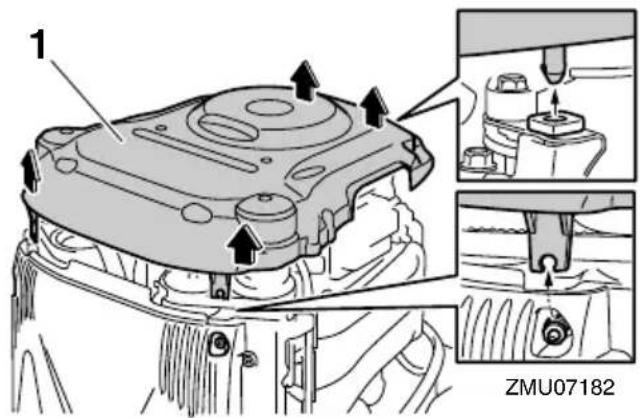
-
Flywheel magnet cover
-
Remove the ECM (Electronic Control Module) cover.
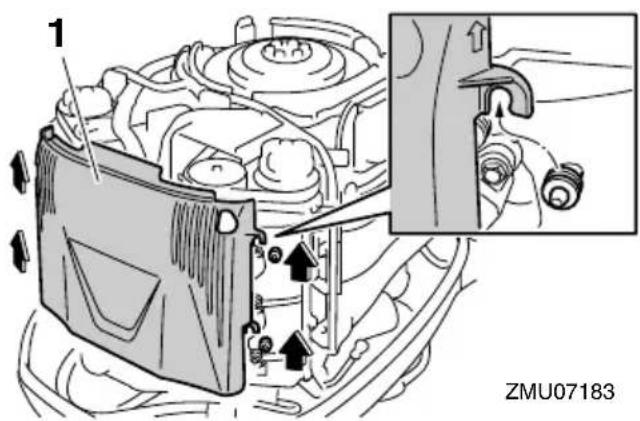
-
ECM (Electronic Control Module) cover
-
Remove the bolt that is securing the ignition coil, and then remove the ignition coil. NOTICE: Do not use any tools to remove or install the ignition coil.
Otherwise, the ignition coil coupler could be damaged. [ECM02330]
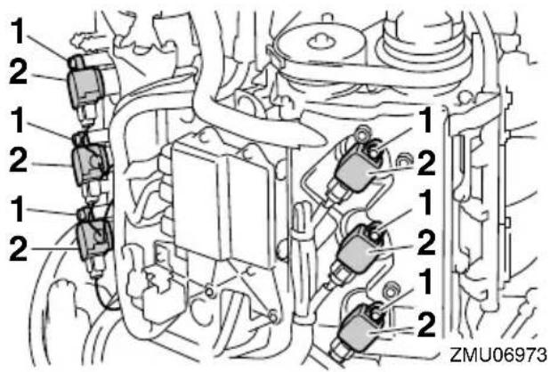
- Bolt
-
Ignition coil
-
Remove the spark plug. WARNING! When removing or installing a spark plug, be careful not to damage the insulator. A damaged insulator could allow external sparks, which could lead to explosion or fire. [EWM00561]
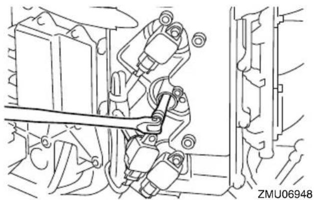
natural_image
Technical line drawing of a mechanical assembly with no visible text or symbolsTo check the spark plug
- Check the condition of the spark plug. If electrode erosion becomes excessive or carbon and other deposits are excessive, replace the spark plug with the specified plug.
Standard spark plug: LFR6A-11
- Measure the spark plug gap using a
thickness gauge. If the spark plug gap is out of specification, replace the spark plug with the specified plug.
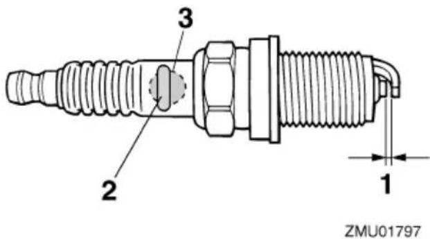
- Spark plug gap
- Spark plug part number
- Spark plug I.D. mark (NGK)
Spark plug gap:
1.0–1.1 mm (0.039–0.043 in)
To install the spark plug
- Wipe off any dirt from the threads, insulator, and gasket surface of the spark plug.
- Install the spark plug, and then tighten it to the specified torque.
Spark plug tightening torque:
28 Nm (2.86 kgf-m, 20.7 ft-lb)
TIP:
If a torque-wrench is not available when you are reinstalling a spark plug, a good estimate of the correct torque is 1/12 turn past finger-tight. When you are installing a new spark plug, a good estimate of the correct torque is 1/2 to 2/3 turn past finger-tight.
3. Install the ignition coil, and then tighten the bolt to the specified torque.
Bolt tightening torque:
8 Nm (0.82 kgf-m, 5.9 ft-lb)
- Install the ECM cover.
- Install the flywheel magnet cover.
EMU41871
Inspecting engine idle speed
ECM01690
NOTICE
This procedure must be performed while the outboard motor is in the water.
Inspect the engine idle speed using the meter that is equipped on the boat. Results may vary depending on whether testing is conducted with the outboard motor in the water.
- Start the engine and allow it to warm up fully in neutral until it is running smoothly.
- Inspect the engine idle speed. If the engine idle speed is out of specification, consult a Yamaha dealer or other qualified mechanic.
Idle speed (in neutral):
650-750 r/min
EMU41205
Changing engine oil
EWM00760

WARNING
- Avoid draining the engine oil immediately after stopping the engine. The oil is hot and should be handled with care to avoid burns.
- Be sure the outboard motor is securely fastened to the transom or a stable stand.
ECM01710
NOTICE
Change the engine oil after the first 20 hours of operation or 3 months, and every 100 hours or at 1-year intervals thereafter. Otherwise the engine will wear
quickly.
To prevent spilling oil where it could cause damage to nature, it is strongly recommended that you use an oil changer to change the engine oil. If an oil changer is not available, drain the engine oil by removing the drain screw. If you are not familiar with the procedure for changing the engine oil, consult your Yamaha dealer.
Changing the engine oil using an oil changer (recommended)
- Put the outboard motor in an upright position (not tilted). NOTICE: If the outboard motor is not level, the oil level indicated on the oil dipstick may not be accurate. [ECM01861]
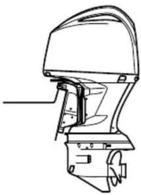
natural_image
Technical line drawing of a boat's side view showing hull, blade, and handle components (no text or labels)ZMU05843
- Start the engine. Warm it up and keep the idle speed for 5-10 minutes.
- Stop the engine and leave it for 5-10 minutes.
- Remove the top cowling.
- Remove the oil filler cap.
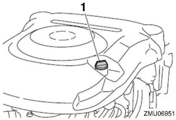
-
Oil filler cap
-
Remove the oil dipstick.
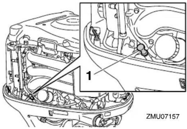
-
Oil dipstick
-
Insert the tube of the oil changer into the oil dipstick guide, and then extract the engine oil completely.
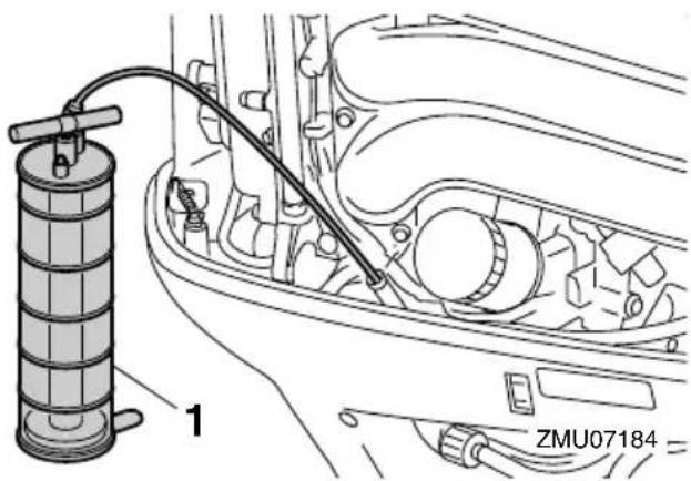
-
Oil changer
-
Add the correct amount of oil through the
filler hole. NOTICE: Overfilling the oil could cause leakage or damage. If the oil level is above the upper level mark, drain until the level meets the specified capacity. [ECM01850]

natural_image
Line drawing of a person using a coiled hose to interact with a circular object (no text or symbols)Recommended engine oil:
YAMALUBE 4M FC-W or 4-stroke outboard motor oil
Engine oil quantity (without oil filter replacement):
6.0 L (6.34 US qt, 5.28 Imp.qt)
Engine oil quantity (with oil filter replacement):
6.3 L (6.66 US qt, 5.54 Imp.qt)
- Install the oil filler cap and oil dipstick.
- Leave the outboard motor for 5-10 minutes.
- Remove the oil dipstick and wipe it clean.
- Insert the dipstick and remove it again. Be sure to completely insert the dipstick into the dipstick guide, otherwise the oil level measurement will be incorrect.
- Recheck the oil level using the dipstick to be sure the level falls between the upper and lower marks. Consult your Yamaha dealer if the oil level is out of specified level.

- Oil dipstick
- Upper mark
-
Lower mark
-
Start the engine and make sure that the low oil pressure-alert indicator remains off. Also, make sure that there are no oil leaks. NOTICE: If the low oil pressure-alert indicator comes on or if there are oil leaks, stop the engine and find the cause. Continued operation with a problem could cause severe engine damage. Consult your Yamaha dealer if the problem cannot be located and corrected. [ECM01622]
-
Install the top cowling.
- Dispose of used oil according to local regulations.
TIP:
- For more information on the disposal of used oil, consult your Yamaha dealer.
- Change the oil more often when operating the engine under adverse conditions such as extended trolling.
Changing the engine oil by draining the oil
- Put the outboard motor in an upright position (not tilted). NOTICE: If the outboard motor is not level, the oil level indicated on the oil dipstick may not be accurate. [ECM01861]

natural_image
Technical line drawing of a boat's head and side panel (no text or symbols)ZMU05843
- Start the engine. Warm it up and keep the idle speed for 5-10 minutes.
- Stop the engine and leave it for 5-10 minutes.
- Remove the top cowling.
- Remove the screws.
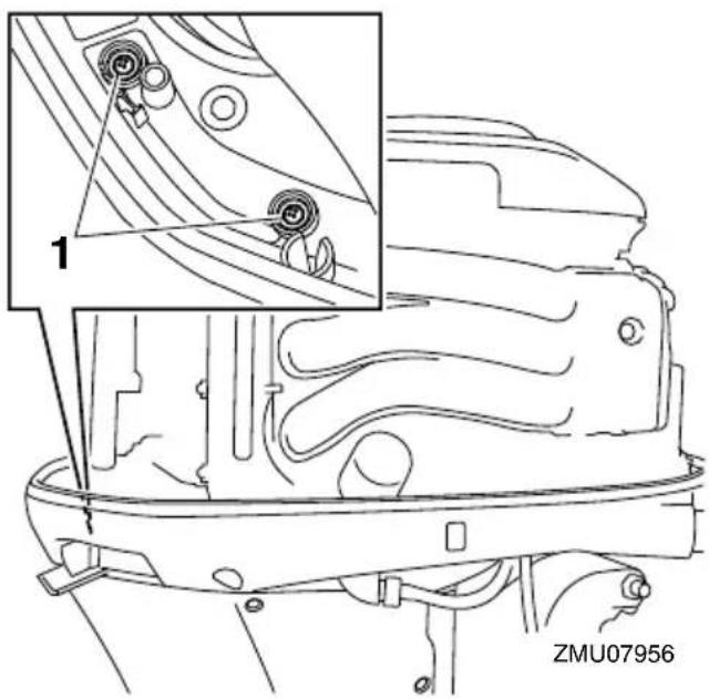
- Screw
- Remove the bolts.
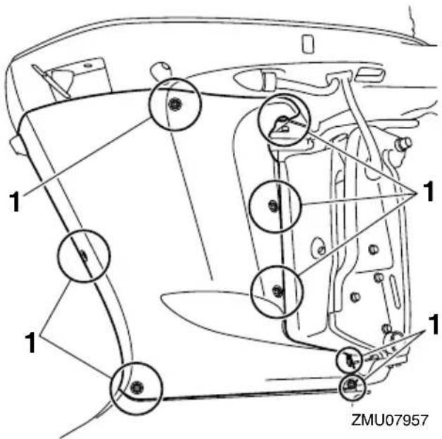
-
Bolt
-
Remove the apron from starboard side as shown in the illustration.
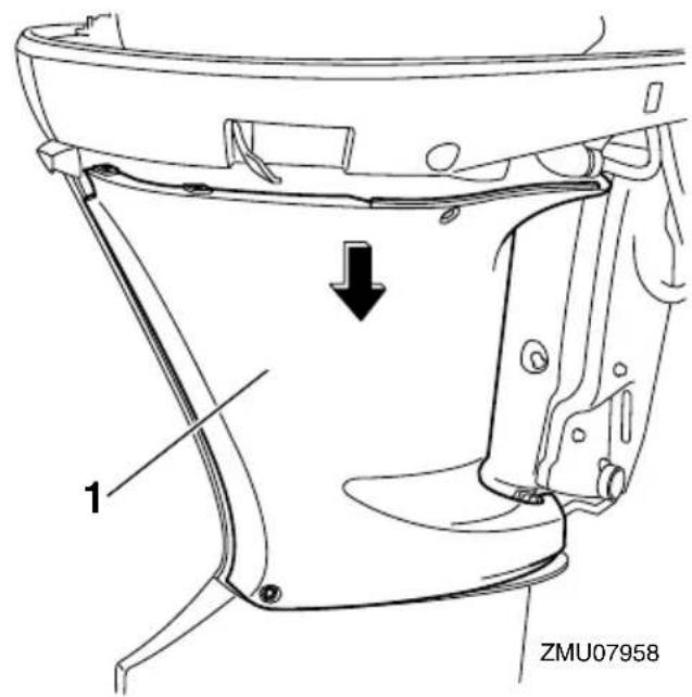
- Apron
- Remove the oil filler cap.

-
Oil filler cap
-
Prepare a suitable container that holds a larger amount than the engine oil capacity. Remove the drain screw and gasket while holding the container under the drain hole. Let the oil drain completely. Wipe up any spilled oil immediately.
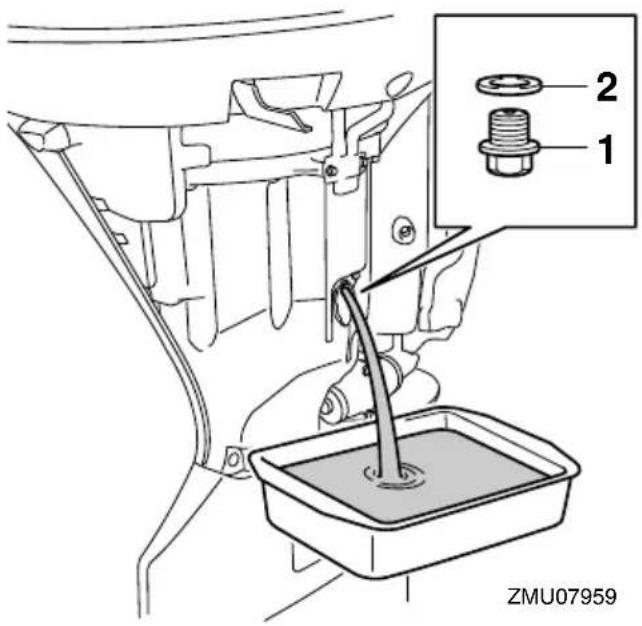
-
Drain screw
-
Gasket
TIP:
If the oil does not drain easily, change the tilt angle or turn the outboard motor to port and starboard to drain the oil.
- Put a new gasket on the drain screw.
Apply a light coat of oil to the gasket and install the drain screw.
Drain screw tightening torque: 27 Nm (2.75 kgf-m, 19.9 ft-lb)
TIP:
If a torque wrench is not available when you are installing the drain screw, finger tighten the screw just until the gasket comes into contact with the surface of the drain hole. Then tighten 1/4 to 1/2 turn more. Tighten the drain screw to the correct torque with a torque wrench as soon as possible.
- Add the correct amount of oil through the filler hole. NOTICE: Overfilling the oil could cause leakage or damage. If the oil level is above the upper level mark, drain until the level meets the specified capacity. [ECM01850]
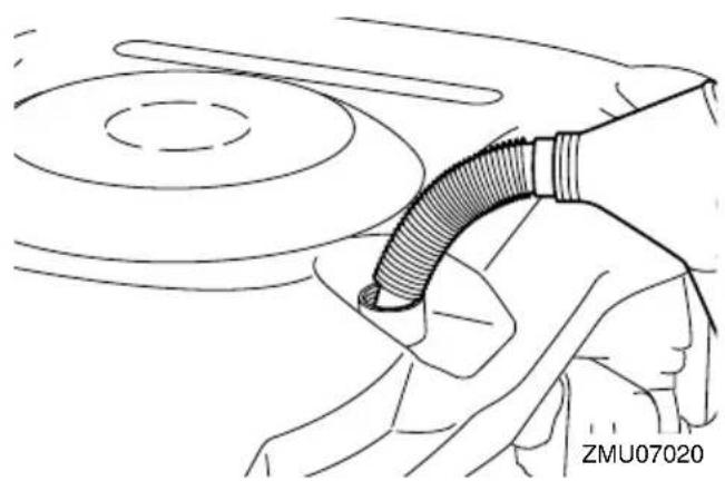
natural_image
Line drawing of a person using a handheld device to interact with a circular component (no text or symbols visible)Recommended engine oil:
YAMALUBE 4M FC-W or 4-stroke outboard motor oil
Engine oil quantity (without oil filter replacement):
6.0 L (6.34 US qt, 5.28 Imp.qt)
Engine oil quantity (with oil filter replacement):
6.3 L (6.66 US qt, 5.54 Imp.qt)
-
Install the oil filler cap.
-
Leave the outboard motor for 5-10 minutes.
- Remove the oil dipstick and wipe it clean.
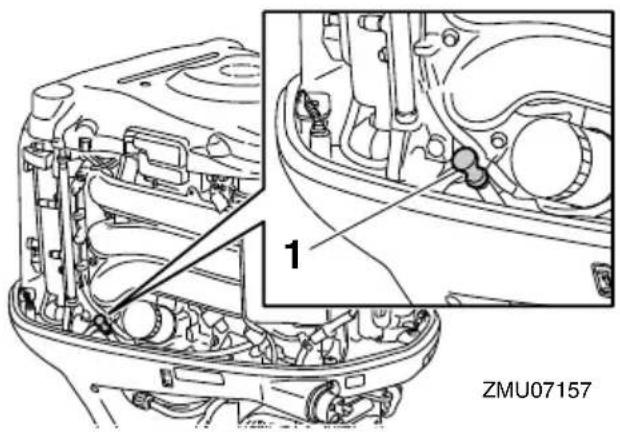
-
Oil dipstick
-
Insert the dipstick and remove it again. Be sure to completely insert the dipstick into the dipstick guide, otherwise the oil level measurement will be incorrect.
- Recheck the oil level using the dipstick to be sure the level falls between the upper and lower marks. Consult your Yamaha dealer if the oil level is out of specified level.
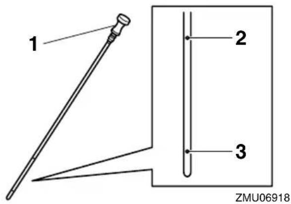
- Oil dipstick
- Upper mark
-
Lower mark
-
Start the engine and make sure that the low oil pressure-alert indicator remains
off. Also, make sure that there are no oil leaks. NOTICE: If the low oil pressure-alert indicator comes on or if there are oil leaks, stop the engine and find the cause. Continued operation with a problem could cause severe engine damage. Consult your Yamaha dealer if the problem cannot be located and corrected. [ECM01622]
- Install the apron on the starboard side as shown in the illustration.
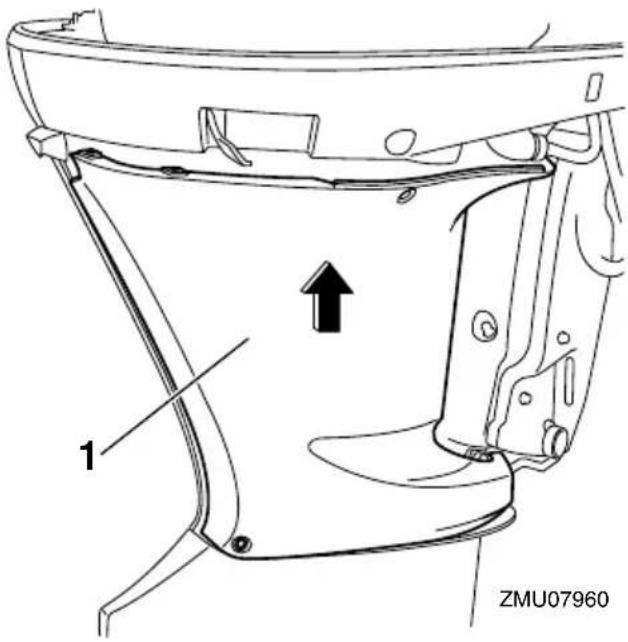
-
Apron
-
Apply LOCTITE 572 to the threads of the bolts and then install the bolts.
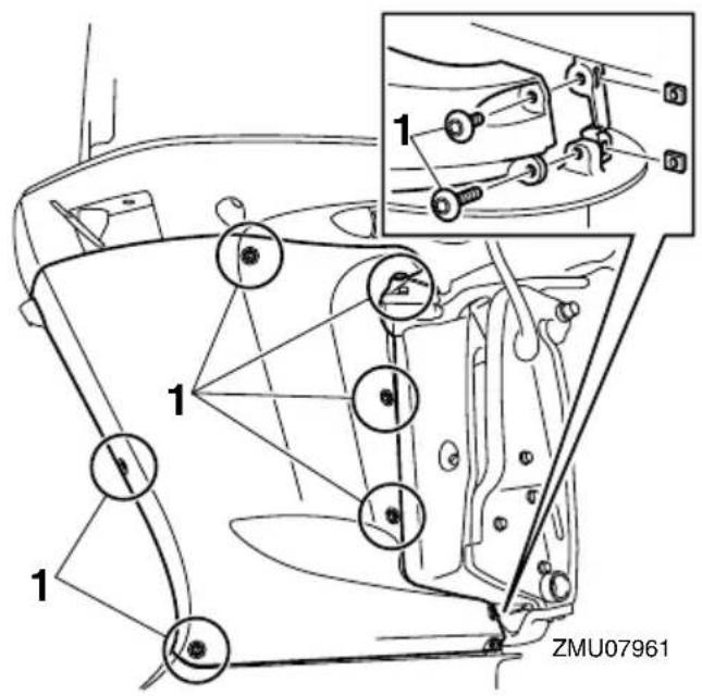
-
Bolt
-
Apply LOCTITE 572 to the threads of the screws and then install the screws.
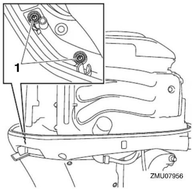
- Screw
TIP:
LOCTITE 572 is used as a sealant.
- Install the top cowling.
- Dispose of used oil according to local regulations.
TIP:
- For more information on the disposal of used oil, consult your Yamaha dealer.
- Change the oil more often when operating the engine under adverse conditions such as extended trolling.
EMU29114
Inspecting wiring and connectors
- Inspect that each connector is engaged securely.
- Inspect that each ground lead is properly secured.
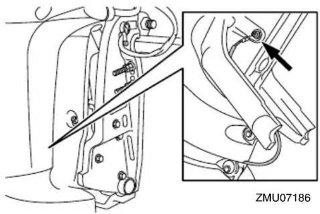
natural_image
Technical line drawing of a mechanical component with two views (top and side), no visible text or symbols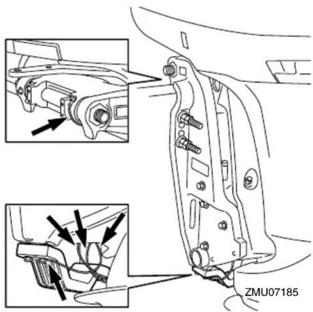
EMU41670
Inspecting propeller
EWM02680

WARNING
You could be seriously injured if the en-
gine accidentally starts when you are near the propeller. Before inspecting, removing, or installing the propeller, move the control lever to the neutral position, turn the main switch to the “Off (off) position, remove the key, and remove the clip from the engine shut-off switch. Turn off the battery cut-off switch if your boat has one.
Do not use your hand to hold the propeller when loosening or tightening the propeller nut. Place a block of wood between the anti-cavitation plate and the propeller to prevent the propeller from turning.
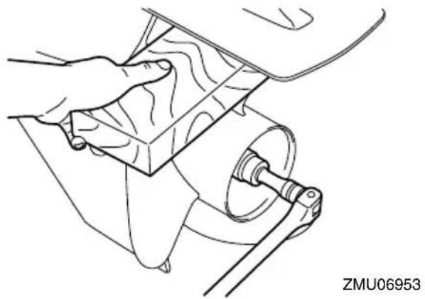
natural_image
Line drawing of a hand operating a mechanical component with a circular component (no text or symbols)Checkpoints
- Check each of the propeller blades for erosion from cavitation or ventilation, and other damage.
- Check the propeller shaft for damage.
- Check the splines for wear and damage.
- Check for fish line tangled around the propeller shaft.
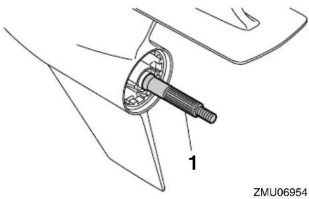
natural_image
Technical line drawing of a mechanical component with labeled part '1' and identifier 'ZMU06954' (no text or symbols on the diagram itself)- Propeller shaft
EMU41991
Removing propeller
- Straighten the cotter pin and pull it out using a pair of pliers.
- Remove the propeller nut, washer, and spacer. WARNING! Do not use your hand to hold the propeller when loosening the propeller nut. [EWM01890]

- Cotter pin
- Propeller nut
- Washer
- Spacer
- Propeller
-
Thrust washer
-
Remove the propeller and thrust washer.
EMU41980
Installing propeller
EWM00770
WARNING
On counter rotation models, be sure to use a propeller intended for counterclockwise rotation. These propellers are identified with the letter "L" after the size indication on the propeller. Otherwise the boat could move in the opposite direction from that expected.
ECM00501
NOTICE
Make sure to use a new cotter pin and bend the ends over securely. Otherwise, the propeller could come off during operation and be lost.
- Apply Yamalube Marine Grease to the propeller shaft.
- Install the thrust washer and propeller on the propeller shaft. NOTICE: Make sure to install the thrust washer before installing the propeller. Otherwise, the lower case and propeller boss could be damaged. [ECM01881]
- Install the spacer, washer, and propeller nut. Tighten the propeller nut to the specified torque.
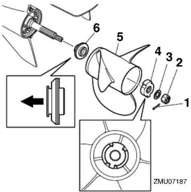
- Cotter pin
- Propeller nut
- Washer
- Spacer
- Propeller
- Thrust washer
Propeller nut tightening torque: 54 Nm (5.51 kgf-m, 39.8 ft-lb)
TIP:
Make sure to align the protrusions on the spacer with the cutout areas of the propeller.
- Align the propeller nut slot with the propeller shaft hole. Insert a new cotter pin in the hole and bend the cotter pin ends. NOTICE: Do not reuse the cotter pin. Otherwise, the propeller can come off during operation. [ECM01891]
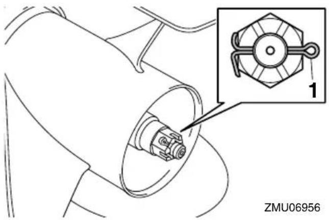
- Cotter pin
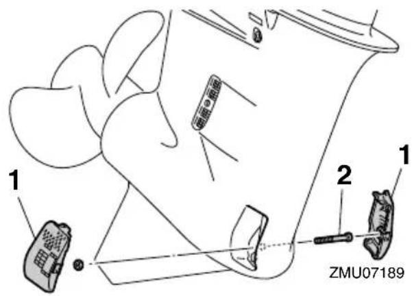
- Cooling water inlet cover
- Bolt
TIP:
If the propeller nut slot does not align with the propeller shaft hole after tightening the propeller nut to the specified torque, tighten the nut further to align the slot with the hole.
EMU41192
Changing gear oil
EWM02530
WARNING
- Make sure that the outboard motor is mounted securely to the transom or a stable stand. You could be severely injured if the outboard motor falls on you.
- Never get under the lower unit while it is tilted. Severe injury could occur if the outboard motor accidentally falls.
Before filling the lower unit with gear oil, the outboard motor must be placed in a vertical position. If you are not able to place the outboard motor in a vertical position, have a Yamaha dealer change the gear oil.
- Tilt the outboard motor so that the gear oil drain screw is at the lowest point possible.
- Place a suitable container under the gear case.
-
Loosen the bolt, and then remove the cooling water inlet covers on both sides of the gear case.
-
Remove the gear oil drain screw and gasket.
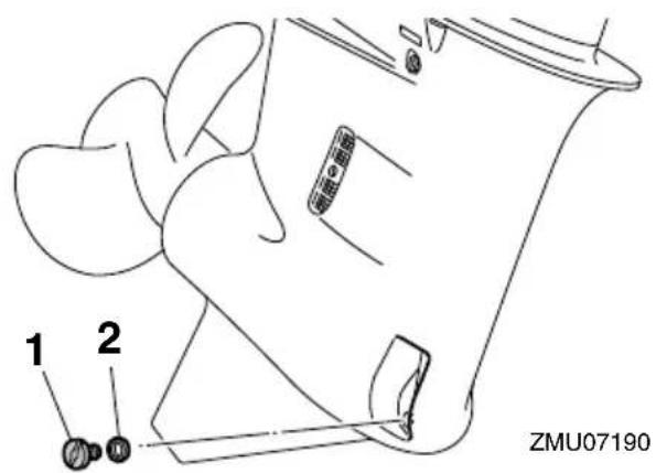
- Gear oil drain screw
-
Gasket
-
Remove the oil level plug and gasket to allow the gear oil to drain completely. NOTICE: Check the used gear oil after it has been drained. If the gear oil is milky or contains water or a large amount of metal particles, the gear case may be damaged. Have a Yamaha dealer check and repair the outboard motor. [ECM00713]
TIP:
For disposal of used gear oil, consult your Yamaha dealer.
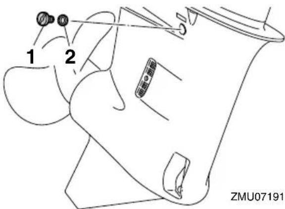
- Oil level plug
-
Gasket
-
Remove any metal particles on the magnetic gear oil drain screw. NOTICE: If there is an excessive quantity of metal particles on the magnetic gear oil drain screw, this can indicate lower unit problem. Consult your Yamaha dealer. [ECM01900]
- Place the outboard motor in a vertical position. Using a flexible or pressurized filling device, inject the gear oil into the gear oil drain screw hole.
Recommended gear oil:
Yamalube Marine Gearcase Lube or Hypoid gear oil
Recommended gear oil grade:
SAE 80W API GL-5 / SAE 90 API GL-5
Gear oil quantity:
1.040 L (1.099 US qt, 0.915 Imp.qt)
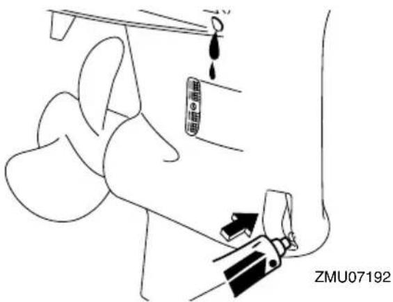
- Put a new gasket on the oil level plug. When the gear oil begins to flow out of the oil level plug hole, insert and tighten the oil level plug to the specified torque.
Tightening torque:
9 Nm (0.92 kgf-m, 6.6 ft-lb)
- Put a new gasket on the gear oil drain screw. Insert and tighten the gear oil drain screw to the specified torque.
Tightening torque:
9 Nm (0.92 kgf-m, 6.6 ft-lb)
- Install the cooling water inlet covers on both sides of the gear case, and then tighten the bolt to the specified torque.
Tightening torque:
2.0 Nm (0.20 kgf-m, 1.5 ft-lb)
EMU29316
Inspecting and replacing anode(s)
Yamaha outboard motors are protected from corrosion by sacrificial anodes. Inspect the external anodes periodically. Remove scales from the surfaces of the anodes. Consult a Yamaha dealer for replacement of external anodes.
ECM00720
NOTICE
Do not paint anodes, as this would render
them ineffective.

natural_image
Technical illustration of a boat's side gear assembly showing top and front views (no text or symbols)ZMU07193
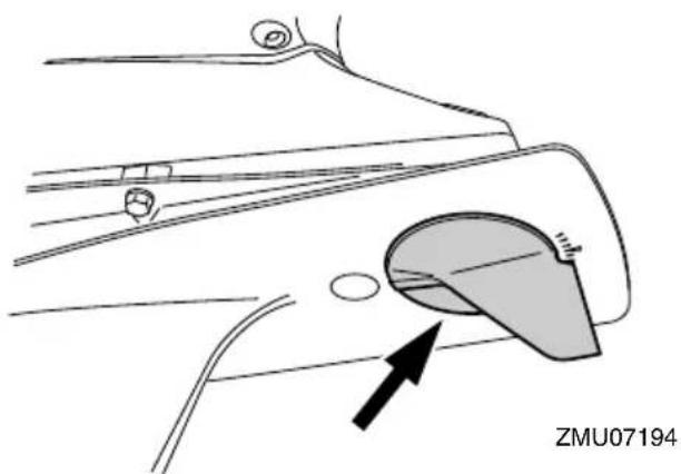
natural_image
Diagram of a car interior showing a handle and seat with an arrow pointing to the seat area (no text or symbols present)TIP:
Inspect ground leads attached to external anodes on equipped models. Consult a Yamaha dealer for inspection and replacement of internal anodes attached to the power unit.
EMU29323
Checking battery (for electric start models)
EWM01902

WARNING
Battery electrolyte is poisonous and caustic, and batteries generate explosive hydrogen gas. When working near the battery:
- Wear protective eye gear and rubber gloves.
- Do not smoke or bring any other source of ignition near the battery.
The procedure for checking the battery varies for different batteries. This procedure contains typical checks that apply to many batteries, but you should always refer to the battery manufacturer's instructions.
ECM01920
NOTICE
A poorly maintained battery will quickly deteriorate.
- Check the electrolyte level.
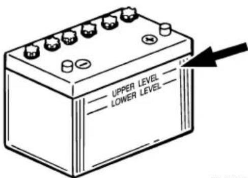
ZMU01810
- Check the battery's charge. If your boat is equipped with the digital speedometer, the voltmeter and low battery alert functions will help you monitor the battery's charge. If the battery needs charging, consult your Yamaha dealer.
- Check the battery connections. They
should be clean, secure, and covered by an insulating cover. WARNING! Bad connections can produce shorting or arcing and cause an explosion.
[EWM01912]
EMU35495
Connecting the battery
EWM00572

Mount the battery holder securely in a dry, well-ventilated, vibration-free location in the boat. Install a fully charged battery in the holder.
ECM01124
NOTICE
Do not reverse the battery cables. Otherwise, the electrical parts could be damaged.
- Make sure the main switch (on applicable models) is "OR(Off) before working on the battery.
- Connect the red battery cable to the POSITIVE (+) terminal first. Then connect the black battery cable to the NEGATIVE (-) terminal.
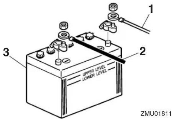
- Red cable
- Black cable
-
Battery
-
The electrical contacts of the battery and cables must be clean and properly con-
nected, or the battery will not start the engine.
Connecting an accessory battery (optional)
- If connecting an accessory battery, consult your Yamaha dealer about correct wiring. For the fuse size, see ABYC (E-11).
Single engine
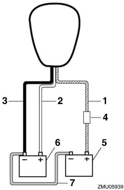
- Isolator lead with circuit protection
- Red cable
- Black cable
- Fuse
- Battery for accessories
- Battery for starting
- Negative connecting cable
Twin engines
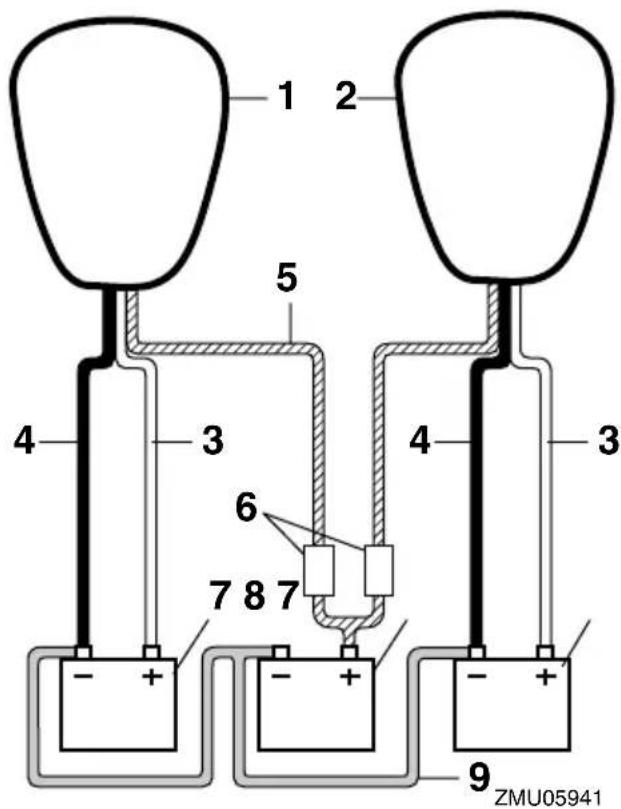
- Starboard side engine
- Port side engine
- Red cable
- Black cable
- Isolator lead with circuit protection
- Fuse
- Battery for starting
- Battery for accessories
-
Negative connecting cable
-
Disconnect the positive cable(s) and remove the battery from the boat.
-
Clean, maintain, and store the battery according to the manufacturer's instructions.
EMU29371
Disconnecting the battery
-
Turn off the battery cut-off switch (if equipped) and main switch. NOTICE: If they are left on, the electrical system can be damaged. [ECM01930]
-
Disconnect the negative cable(s) from the negative (-) terminal. NOTICE: Always disconnect all negative (-) cables first to avoid a short circuit and damage to the electrical system.
[ECM01940]
EMU41860
Troubleshooting
This section describes the likely causes and remedies for problems, such as those in the fuel, compression, and ignition systems, poor starting, and loss of power. Please note that all of the items in this section may not apply to your model.
If your outboard motor requires repair, bring it to a Yamaha dealer.
If the engine trouble-alert indicator is blinking, consult your Yamaha dealer.
Starter will not operate.
Q. Does the Digital electronic control-alert indicator come on?
A. Have serviced by a Yamaha dealer.
Q. Is control lever in gear?
A. Shift to neutral.
Q. Is battery capacity low or weak?
A. Check battery condition. Use battery of recommended capacity.
Q. Are battery connections corroded or loose?
A. Tighten battery cables and clean battery terminals.
Q. Is fuse for starter relay or electric circuit blown?
A. Check for cause of electric overload and repair. Replace fuse with one of correct amperage.
Q. Are starter components malfunctioning?
A. Have serviced by a Yamaha dealer.
Engine will not start (starter operates).
Q. Is clip on engine shut-off cord (lanyard) in-
stalled?
A. Install clip to engine shut-off switch.
Q. Is fuel tank empty?
A. Fill tank with clean, fresh fuel.
Q. Is fuel contaminated or stale?
A. Fill tank with clean, fresh fuel.
Q. Is fuel filter clogged?
A. Clean or replace fuel filter.
Q. Is fuel pump malfunctioning?
A. Have serviced by a Yamaha dealer.
Q. Are spark plugs fouled or of incorrect type?
A. Inspect spark plugs. Clean or replace with recommended type.
Q. Are ignition parts malfunctioning?
A. Have serviced by a Yamaha dealer.
Q. Is ignition wiring damaged or poorly connected?
A. Inspect wires for breaks and wear. Have connections tightened and broken or worn wires replaced by a Yamaha dealer.
Q. Are engine inner parts damaged?
A. Have serviced by a Yamaha dealer.
Engine idles irregularly or stalls.
Q. Are spark plugs fouled or of incorrect type?
A. Inspect spark plugs. Clean or replace with recommended type.
Q. Is fuel system clogged?
A. Inspect for pinched or kinked fuel line or other obstructions in fuel system.
Q. Is fuel contaminated or stale?
A. Fill tank with clean, fresh fuel.
Q. Is fuel filter clogged?
A. Clean or replace fuel filter.
Q. Are ignition parts malfunctioning?
A. Have serviced by a Yamaha dealer.
Q. Has alert system activated?
A. Find and correct cause of alert.
Q. Is spark plug gap incorrect?
Q. Is ignition wiring damaged or poorly connected?
A. Inspect wires for breaks and wear. Have connections tightened and broken or worn wires replaced by a Yamaha dealer.
Q. Is specified engine oil not being used?
A. Inspect engine oil and replace with specified type.
Q. Is thermostat clogged or malfunctioning?
A. Have serviced by a Yamaha dealer.
Q. Is fuel pump malfunctioning?
A. Have serviced by a Yamaha dealer.
Q. Is fuel tank air vent restricted or clogged?
A. Remove obstruction.
Q. Is fuel joint connection incorrect?
A. Connect correctly.
Q. Is battery cable disconnected?
A. Connect securely.
Alert buzzer sounds or indicator lights.
Q. Is cooling system clogged?
A. Inspect cooling water inlet for obstructions.
Q. Is low oil pressure-alert indicator on or blinking?
A. Have serviced by a Yamaha dealer.
Q. Is heat range of spark plugs incorrect?
A. Inspect spark plugs and replace with recommended type.
Q. Is specified engine oil not being used?
A. Inspect engine oil and replace with specified type.
Q. Is engine oil contaminated or deteriorated?
A. Replace engine oil with specified type.
Q. Is oil filter clogged?
A. Have serviced by a Yamaha dealer.
Q. Is oil pump malfunctioning?
A. Have serviced by a Yamaha dealer.
Q. Is thermostat or water pump malfunctioning?
A. Have serviced by a Yamaha dealer.
Q. Is there excess water in fuel filter?
A. Drain fuel filter.
Engine power loss.
Q. Is propeller damaged?
A. Have propeller repaired or replaced.
Q. Is propeller pitch or diameter incorrect?
A. Install correct propeller to operate outboard motor at its recommended speed
(r/min) range.
Q. Is outboard motor mounted at incorrect height on transom?
A. Have outboard motor adjusted to proper transom height.
Q. Has alert system activated?
A. Find and correct cause of alert.
Q. Is boat bottom fouled with marine growth?
A. Clean boat bottom.
Q. Are spark plugs fouled or of incorrect type?
A. Inspect spark plugs. Clean or replace with recommended type.
Q. Are weeds or other foreign material tangled on gear housing?
A. Remove foreign material and clean lower unit.
Q. Is fuel system clogged?
A. Inspect for pinched or kinked fuel line or other obstructions in fuel system.
Q. Is fuel filter clogged?
A. Clean or replace fuel filter.
Q. Is fuel contaminated or stale?
A. Fill tank with clean, fresh fuel.
Q. Is spark plug gap incorrect?
Q. Is ignition wiring damaged or poorly connected?
A. Inspect wires for breaks and wear. Have connections tightened and broken or worn wires replaced by a Yamaha dealer.
Q. Are electrical parts malfunctioning?
A. Have serviced by a Yamaha dealer.
Q. Is specified fuel not being used?
A. Replace fuel with specified type.
Q. Is specified engine oil not being used?
A. Replace engine oil with specified type.
Q. Is thermostat clogged or malfunctioning?
A. Have serviced by a Yamaha dealer.
Q. Is fuel tank air vent restricted or clogged?
A. Remove obstruction.
Q. Is fuel pump malfunctioning?
A. Have serviced by a Yamaha dealer.
Q. Is fuel joint connection incorrect?
A. Connect correctly.
Q. Is heat range of spark plugs incorrect?
A. Inspect spark plugs and replace with recommended type.
Q. Is engine not responding properly to control lever position?
A. Have serviced by a Yamaha dealer.
Engine vibrates excessively.
Q. Is propeller damaged?
A. Have propeller repaired or replaced.
Q. Is propeller shaft damaged?
A. Have serviced by a Yamaha dealer.
Q. Are weeds or other foreign material tangled on propeller?
A. Remove and clean propeller.
Q. Are outboard motor mounting bolts loose?
A. Tighten bolts or have serviced by a Yamaha dealer.
Q. Is steering pivot loose or damaged?
A. Have serviced by a Yamaha dealer.
EMU29433
Temporary action in emergency
EMU29441
Impact damage
EWM00870

The outboard motor can be seriously damaged by a collision while operating or trailering. Damage could make the outboard motor unsafe to operate.
If the outboard motor hits an object in the water, follow the procedure below.
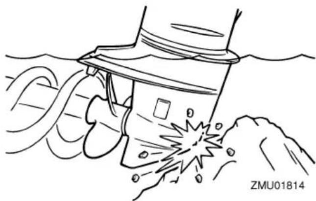
natural_image
Line drawing of a mechanical device emitting sparks from a surface, with no visible text or symbols- Stop the engine immediately.
- Check the control system and all components for damage. Also, check the boat for damage.
- Whether damage is found or not, return to the nearest harbor slowly and carefully.
- Have a Yamaha dealer check the outboard motor before operating it again.
EMU29453
Running single engine (twin engines)
When using only one engine in an emergency, be sure to keep the unused one tilted up and operate the other engine at low speed.
ECM00370
NOTICE
If the boat is operated with one engine in the water but not running, water may run into the exhaust pipe due to wave action, causing engine trouble.
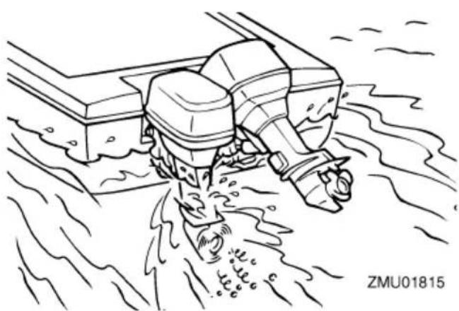
natural_image
Line drawing of a boat being plunged into water, no text or symbols presentTIP:
When you are maneuvering at low speed, such as near a dock, it is recommended that both engines be running with one in neutral gear if possible.
EMU41880
Replacing fuse
EWM00631

Substituting an incorrect fuse or a piece of wire could allow excessive current flow. This could cause electric system damage and a fire hazard.
If a fuse has blown, replace the fuse according to the following procedure.
- Turn the main switch to the "o(off) position.
- Remove the fuse box cover.
- When replacing the main fuse or isolater fuse, remove the screws, and then remove the fuse. Install the spare fuse, and then tighten the screws.
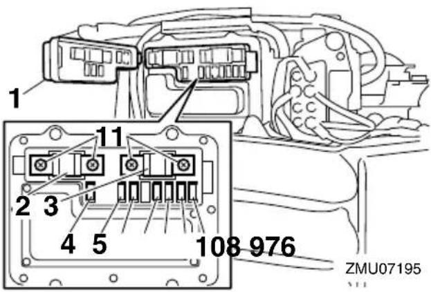
- Fuse box cover
- Main fuse (100 A)
- Isolator fuse (100 A)
- Fuel feed pump fuse (10 A)
- Main switch / PTT switch / Digital electronic control ECM (Electronic control module) fuse (20 A)
- Shift actuator fuse (15 A)
- Starting switch (30 A)
- Ignition coil / Fuel injector / Variable camshaft timing / Engine ECM (Electronic control module) fuse (30 A)
- Electric throttle valve fuse (10 A)
- Fuel pump fuse (15 A)
- Screw
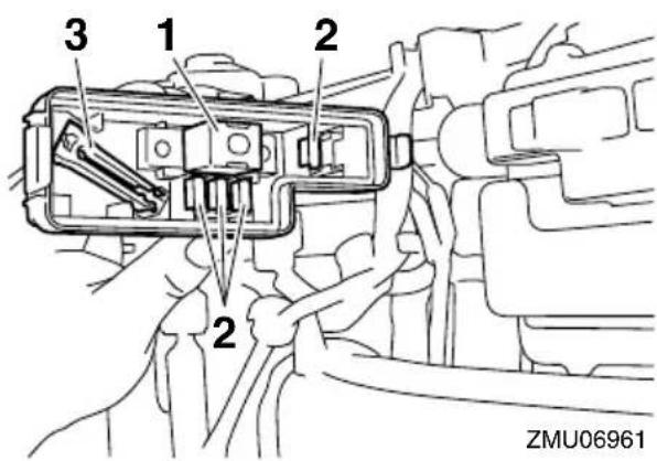
- Spare fuse (100 A)
- Spare fuse (10 A, 15 A, 20 A, 30 A)
-
Fuse puller
-
When replacing a fuse other than the main fuse or isolater fuse, remove the
fuse using the fuse puller. Install a spare fuse of the proper amperage.
Consult your Yamaha dealer if the new fuse immediately blows again.
EMU40982
Power trim and tilt unit will not operate
EWM02330

WARNING
Never get under the engine while it is tilted. Severe injury could occur if the outboard motor accidentally falls.
If the outboard motor cannot be tilted up or down using the power trim and tilt unit because of a discharged battery or a failure with the power trim and tilt unit, the outboard motor can be tilted manually.
- Stop the engine.
- Loosen the manual valve screw by turning it counterclockwise until it stops.
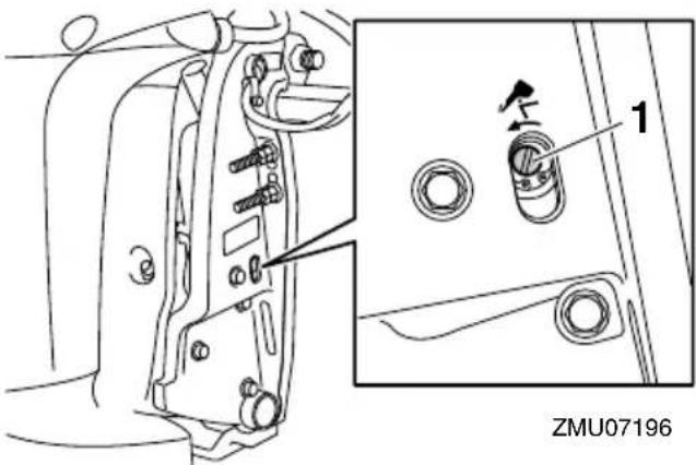
-
Manual valve screw
-
Tilt the outboard motor up manually to the desired position, and then tighten the manual valve screw by turning it clockwise.
EMU41890
Water separator-alert indicator blinks while cruising
EWM02542

WARNING
Gasoline is highly flammable, and its vapors are flammable and explosive.
- Do not perform this procedure on a hot or running engine. Allow the engine to cool.
- There will be fuel in the fuel filter. Keep away from sparks, cigarettes, flames or other sources of ignition.
- Some fuel will spill during this procedure. Catch the fuel in a rag. Wipe up any spilled fuel immediately.
- The fuel filter must be reassembled carefully with the O-ring and filter cup in place. Improper assembly or replacement could result in a fuel leak, which could result in a fire or explosion hazard.
If the water separator-alert indicator blinks, perform the following procedure.
- Stop the engine.
- Remove the top cowling.
- Remove the bolts, and then remove the fuel filter cover.
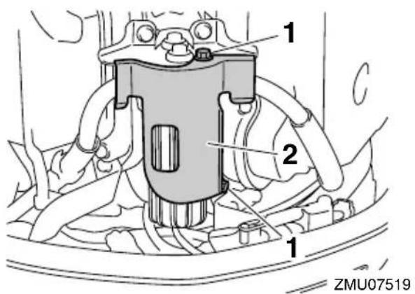
- Bolt
-
Fuel filter cover
-
Disconnect the water detection switch coupler. NOTICE: Be careful not to get any water on the water detection switch coupler, otherwise a malfunction could occur. [ECM01950]
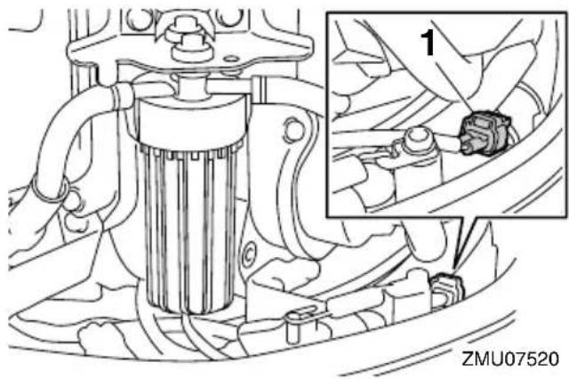
natural_image
Technical line drawing of a mechanical assembly with an inset showing a close-up of a component (no text or symbols present)-
Water detection switch coupler
-
Remove the filter cup from the filter housing, and then remove the O-ring from the filter cup. NOTICE: Be careful not to twist the water detection switch lead when unscrewing the filter cup. [ECM01960]

- Filter housing
- O-ring
- Filter cup
-
Water detection switch lead
-
Drain the water in the filter cup by soaking it up with a rag.
-
Put the O-ring on the filter cup in its orig-
inal position, and then install the filter cup onto the filter housing. NOTICE: Be careful not to twist the water detection switch lead when screwing the filter cup onto the filter housing. ately take it to a Yamaha dealer. Otherwise some corrosion may begin almost immediately. NOTICE: Do not attempt to run the outboard motor until it has been completely inspected. [ECM00401]
[ECM01970]
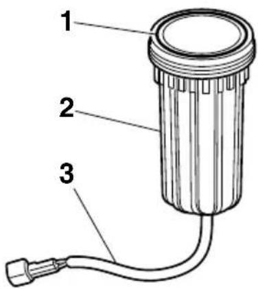
ZMU07522
- O-ring
- Filter cup
-
Water detection switch lead
-
Connect the water detection switch coupler securely until a click is heard.
- Install the fuel filter cover, and then tighten the bolts.
- Install the top cowling.
- Turn the main switch to the “”(on) position and check that the water separator-alert indicator remains off and the buzzer does not sound. If the water separator-alert indicator blinks or the buzzer sounds, have your Yamaha dealer check the outboard motor. NOTICE: Although the buzzer will stop when the engine is started and the control lever is moved to the forward or reverse position, do not use the outboard motor. Otherwise, serious engine damage could occur. [ECM02480]
EMU33501
Treatment of submerged motor
If the outboard motor is submerged, immedi-
EMU29835
YAMAHA FOUR-STROKE OUTBOARD MOTOR THREE-YEAR LIMITED WARRANTY
Yamaha Motor Corporation, U.S.A. and Yamaha Motor Canada Ltd. ("Yamaha") hereby warrant that new Yamaha four-stroke outboard motors will be free from defects in material and workmanship for the period of time stated herein, subject to certain stated limitations.
PERIOD OF WARRANTY. Any new Yamaha four-stroke outboard motor purchased from an authorized Yamaha dealer in the customer's country of residence (United States or Canada) and registered with Yamaha will be warranted against defects in material or workmanship, subject to exclusions noted herein, for the following applicable period determined by type of use:
- Pleasure use – three (3) years from the date of purchase.
- Commercial application – one (1) year from the date of purchase. A commercial application is defined as any use of the outboard motor to generate income (excluding tournament fishing) or support business operations in any way during the warranty period, without regard to the type or percentage of commercial use. Yamaha reserves the right to modify incorrect registration data and reduce the warranty period to reflect commercial use.
- Yamaha peripheral equipment included with the motor, such as gauges, fuel tanks, and hoses, remote control boxes, and wiring external from the motor unit, will be warranted for one (1) year from the date of purchase for either pleasure or commercial use.
Replacement parts used in warranty repairs will be warranted for the balance of the applicable warranty period.
The second and third year of warranty (if applicable) shall be limited to covering the cost of parts and labor for major components only. The major components covered are:
Power Unit Section
- Power Head
- Intake Manifold
- Carburetor Assembly and its Related Components
- Fuel Injection System and its Related Components
- Fuel and Oil Pump Assemblies
- Ignition System (Standard and Microcomputer)
Lower Unit Section Bracket Section
- Exhaust System
- Bracket System
- Upper Casing
• Power Trim and Tilt Assembly - Lower Unit Assembly
WARRANTY REGISTRATION. To be eligible for warranty coverage, the outboard motor must be registered with Yamaha in the country of residence. Warranty registration can be accomplished by any authorized Yamaha Outboard Motor Dealer.
OBTAINING REPAIRS UNDER WARRANTY. During the period of warranty, any authorized Yamaha Outboard Motor Dealer in the country of residence will, free of charge, repair or replace, at Yamaha's option, any parts adjudged defective by Yamaha due to faulty workmanship or material from the factory. All replaced parts will become the property of Yamaha. If the customer is temporarily using a U.S.-registered outboard motor in Canada, or a Canada-registered outboard motor in the United States, and it needs warranty repairs, the owner should contact a nearby authorized Yamaha Outboard Motor Dealer for assistance. The local dealer will contact Yamaha on the owner's behalf so that needed repairs can be made as quickly as possible.
CUSTOMER'S RESPONSIBILITY. Under the terms of this warranty, the customer will be responsible for ensuring that the outboard motor is properly operated, maintained, and stored as specified in the applicable Owner's Manual. The owner of the outboard motor shall give notice to an authorized Yamaha Outboard Motor Dealer of any and all apparent defects within ten (10) days of discovery and make the motor available at that time for inspection and repairs at the dealer's place of business.
ZMU07048
GENERAL EXCLUSIONS FROM WARRANTY. This warranty will not cover the repair of damage if the damage is a result of abuse or neglect of the product. Examples of abuse and neglect include, but are not limited to:
- Racing or competition use, modification of original parts, abnormal strain.
- Lack of proper maintenance and off season storage as described in the Owner's Manual; installation of parts or accessories that are not equivalent in design and quality to genuine Yamaha parts.
- Operation of the motor at an rpm other than specified, use of lubricants or oils that are not suitable for outboard motor use.
- Damage as a result of accidents, collisions, contact with foreign materials, or submersion.
- Growth of marine organism on motor surfaces.
- Normal deterioration.
SPECIFIC PARTS EXCLUDED FROM WARRANTY. Parts replaced due to normal wear or routine maintenance such as oil, spark plugs, shear pins, propellers, hubs, fuel and oil filters, brushes for the starter motor and power tilt motor, water pump impellers, and anodes, are not covered by warranty. Charges for removal of the motor from a boat and transporting the motor to and from an authorized Yamaha Outboard Motor Dealer are excluded from warranty coverage.
Specific parts excluded from the second and third year of warranty (if applicable) are:
• Top and Bottom Cowling
• Electric Components (other than ignition system)
- Rubber Components (such as hoses, tubes, rubber seals, fittings, and clamps)
EMISSION CONTROL WARRANTY (United States only). Yamaha warrants to the ultimate purchaser and any subsequent owner, that the emission control components on this engine are designed, built and equipped so as to conform at the time of sale with applicable regulations under section 213 of the Clean Air Act and that this engine is covered against defects in materials and workmanship which cause said engine to fail to conform with applicable exhaust emission regulations for five (5) years from the date of purchase or 175 hours of operation, whichever comes first. Evaporative components (e.g., hoses, fuel tank, fuel cap) are covered for three (3) years from the date of purchase. Some states have different emission control warranty provisions. As these vary from state to state, consult your Yamaha dealer or contact Yamaha Customer Relations at 1-866-894-1626 for more information.
TRANSFER OF WARRANTY Transfer of the warranty from the original purchaser to any subsequent purchaser is possible by having the motor inspected by an authorized Yamaha Outboard Motor Dealer and requesting the dealer to submit a change of registration to Yamaha within ten (10) days of the transfer.
YAMAHA MAKES NO OTHER WARRANTY OF ANY KIND, EXPRESSED OR IMPLIED. ALL IMPLIED WARRANTIES OF MERCHANTABILITY AND FITNESS FOR A PARTICULAR PURPOSE WHICH EXCEED THE OBLIGATIONS AND TIME LIMITS STATED IN THIS WARRANTY ARE HEREBY DISCLAIMED BY YAMAHA AND EXCLUDED FROM THIS WARRANTY. SOME STATES/PROVINCES DO NOT ALLOW LIMITATIONS ON HOW LONG AN IMPLIED WARRANTY LASTS, SO THE ABOVE LIMITATIONS MAY NOT APPLY TO YOU. ALSO EXCLUDED FROM THIS WARRANTY ARE ANY INCIDENTAL OR CONSEQUENTIAL DAMAGES INCLUDING LOSS OF USE. SOME STATES/PROVINCES DO NOT ALLOW THE EXCLUSION OR LIMITATION OF INCIDENTAL OR CONSEQUENTIAL DAMAGES, SO THE ABOVE EXCLUSION MAY NOT APPLY TO YOU.
THIS WARRANTY GIVES YOU SPECIFIC LEGAL RIGHTS, AND YOU MAY ALSO HAVE OTHER RIGHTS WHICH VARY FROM STATE TO STATE/PROVINCE TO PROVINCE.
ZMU07047
EMU29845
IMPORTANT WARRANTY INFORMATION IF YOU USE YOUR YAMAHA OUTSIDE THE U.S.A. OR CANADA
Welcome to the Yamaha Family!
Congratulations on the purchase of your new Yamaha products. Yamaha is committed to exceptional customer satisfaction and we want your ownership experience to be a satisfying one. Please read the following warranty information to help ensure satisfaction with your Yamaha.
This model was manufactured with specifications appropriate for sale and use in the U.S.A. and Canada. Please note the following information:
-
As explained in the Limited Warranty Statement, the Yamaha warranty covers your Yamaha when it is registered and used in your country of residence. If you are temporarily using a U.S.-registered outboard motor in Canada, or a Canada-registered outboard motor in the United States, and it needs warranty repairs, you should contact a nearby authorized Yamaha Outboard Motor Dealer for assistance. The local dealer will contact Yamaha on the owner's behalf so that needed repairs can be made as quickly as possible.
-
If you need repairs while temporarily using your Yamaha in another country, contact the local authorized Yamaha distributor for that country. Yamaha will work with tha distributor to make the needed repairs as quickly as possible. If you have to pay for a repair that you believe your warranty would have covered at home, present all repair orders, receipts, or other related documents to your local dealer when you return home. He will be able to contact Yamaha on your behalf to see if any refund can be provided.
TIP:
Your Yamaha model may not be sold in some countries. Therefore, a Yamaha deal outside the United States or Canada may not have all of the replacement parts or technical information available to provide proper service. This may unavoidably delay repairs. Thank you for your understanding should this happen.
- If your Yamaha is registered or used primarily outside the United States or Canada, the warranty printed in this manual does not apply to you. Contact the dealer who sold the Yamaha marine power unit to you for customer support information.
ZMU05199
For your best ownership experience, think Genuine Yamaha!
Genuine Yamaha Parts — Genuine Yamaha replacement parts are the exact same parts as the ones originally equipped on your vehicle, providing you with the performance and durability you have come to expect. Why settle for aftermarket parts that may not provide full confidence and satisfaction?
Genuine Yamaha Accessories — Yamaha only offers accessories that meet our high standards for quality and performance. Buy with confidence, knowing your Genuine Yamaha Accessories will fit right and perform right — right out of the box.
Yamalube — Take care of your Yamaha with legendary Yamalube oils, lubricants, and care products. They're formulated and approved by the toughest judges we know: the Yamaha engineering teams that know your Yamaha from the inside out.
Genuine Yamaha Service Manuals — Get the same factory manual for your vehicle that the technicians at your authorized Yamaha dealer use. Service manuals are available through your Yamaha dealer or you can order them directly through yamahapubs.com (USA only).
Genuine Yamaha products are available only from your Yamaha dealer.
Find out more at yamaha-motor.com

YAMAHA
- WARNING
- To the owner
- NOTICE
- TIP:
- Safety information.... 1
- General information 9
- Specifications and requirements .... 14
- Components 24
- Instruments and indicators ...... 36
- Engine control system...... 46
- Installation 50
- Operation 52
- Checks before starting engine ..... 52
- Filling fuel 58
- Maintenance.... 70
- Trouble Recovery....93
- Consumer information ...... 100
- Outboard motor safety
- Propeller
- Rotating parts
- Hot parts
- Electric shock
- Power trim and tilt
- Engine shut-off cord (lanyard)
- Gasoline
- Gasoline exposure and spills
- Carbon monoxide
- Modifications
- Boating safety
- Alcohol and drugs
- Personal flotation devices (PFDs)
- People in the water
- Passengers
- Overloading
- Avoid collisions
- Weather
- Accident reporting
- Boat education and training
- For U.S.A.
- For Canada
- Passenger training
- Boating safety publications
- Laws and regulations
- Boating organizations
- In the U.S.A.
- United States Coast Guard
- United States Power Squadrons
- Boat Owners Association of The United States
- National Association of State Boating Law Administrators (NASBLA)
- National Marine Manufacturers Association (NMMA)
- Marine Retailers Association of America
- In the Canada
- National Marine Manufacturers Association Canada
- Basic boating rules (Rules of the road)
- Steering and sailing rules and sound signals
- Stand-on vessel
- Give-way vessel
- "The general prudential rule"
- Rules when encountering vessels
- Meeting
- Crossing
- Overtaking
- Other special situations
- Narrow channels and bends
- Fishing vessel right-of-way
- Sailing vessel right-of-way
- Reading buoys and other markers
- Identification numbers record
- Outboard motor serial number
- Digital electronic control serial number
- Key number
- EC Declaration of Conformity (DoC)
- CE Marking
- Read manuals and labels
- Warning labels
- 1
- Symbols
- Specifications
- Dimension and weight:
- Performance:
- Power unit:
- Specifications and requirements
- Lower unit:
- Fuel and oil:
- Tightening torque:
- Installation requirements
- Boat horsepower rating
- Overpowering a boat can cause severe instability.
- Mounting outboard motor
- Digital electronic control requirements
- Battery requirements
- Specifications of Battery
- Mounting battery
- Multiple batteries
- Propeller selection
- Counter rotation models
- Start-in-gear protection
- Engine oil requirements
- Fuel requirements
- Gasoline with Ethanol
- Gasoline Filtration
- Gasoline Additives
- Anti-fouling paint
- Outboard motor disposal requirements
- Emergency equipment
- Emission control information
- North American models
- Approval label of emission control certificate
- Manufactured date label
- Star labels
- One Star—Low Emission
- Two Stars—Very Low Emission
- Three Stars—Ultra Low Emission
- Four Stars—Super Ultra Low Emission
- Components diagram
- Digital Electronic Control box
- Digital electronic control-active indicator
- Digital electronic control-alert indicator
- Control lever
- Free throttle switch
- Throttle friction adjuster
- Engine shut-off cord (lanyard) and clip
- Main switch
- Start/Stop switch panel
- All Start/Stop switch panel
- Power trim and tilt switch on digital electronic control
- Power trim and tilt switch on bottom cowling
- Power trim and tilt switches (twin type)
- Trim tab with anode
- Tilt support lever for power trim and tilt model
- Cowling lock lever
- Flushing device
- Components
- Fuel filter
- Command Link Plus Display
- Engine warm-up indicator
- Engine synchronization indicator
- Overheat alert
- Instruments and indicators
- Water separator alert
- Low oil pressure-alert
- Low battery voltage-alert
- Engine trouble alert
- Command Link Multifunction Meters
- Command Link Multifunction Tachometer
- Command Link Multifunction Speed & Fuel Meter
- Command Link Multifunction Speedometer
- Command Link Multifunction Fuel Management Meter
- Optional meters
- Alert system
- Digital Electronic Control alert
- Low oil pressure alert
- Installation
- Mounting the outboard motor
- Mounting height (boat bottom)
- First-time operation
- Filling engine oil
- Breaking in engine
- Procedure for breaking in engine
- Getting to know your boat
- Checks before starting engine
- occur.
- Fuel level
- Removing top cowling
- Fuel system
- Check for fuel leaks
- Checking the fuel filter
- EMU41770
- Controls
- EMU40362
- EMU40993
- Engine oil
- Outboard motor
- Installing top cowling
- Checking power trim and tilt system
- Battery
- Filling fuel
- Operating engine
- Sending fuel
- Starting engine
- Start-up checks
- Procedure for starting engine
- Checks after starting engine
- Cooling water
- Warming up engine
- Electric start models
- Checks after engine warm up
- Shifting
- Stop switches
- ! WARNING
- To shift out of neutral
- Stopping boat
- EWM01510
- Trolling
- Adjusting trolling speed
- Stopping engine
- Procedure for stopping engine
- Trimming outboard motor
- Adjusting trim angle (Power trim and tilt)
- Adjusting boat trim
- Bow Up
- Bow Down
- Tilting up and down
- Procedure for tilting up (power trim and tilt models)
- Procedure for tilting down (power trim and tilt models)
- Shallow water
- Cruising in shallow water
- Procedure for power trim and tilt models
- Operating in other conditions
- Operating in salt water
- Operating in water containing mud, sand, silt, debris, or vegetation
- Transporting and storing outboard motor
- Storing outboard motor
- Store the outboard motor in a dry, well-ventilated place, not in direct sunlight.
- Conditioning and stabilizing gasoline
- Procedure
- Cleaning the outboard motor
- Lubrication
- Cleaning and anticorrosion measures
- Flushing cooling water passage
- Checking painted surface of outboard motor
- Periodic maintenance
- Replacement parts
- Maintenance interval guidelines
- Maintenance chart 1
- Greasing
- Inspecting spark plug
- To remove the spark plug
- To check the spark plug
- To install the spark plug
- Inspecting engine idle speed
- This procedure must be performed while the outboard motor is in the water.
- Changing engine oil
- quickly.
- Changing the engine oil by draining the oil
- Inspecting wiring and connectors
- Inspecting propeller
- Checkpoints
- EMU41991
- Removing propeller
- Installing propeller
- Changing gear oil
- Inspecting and replacing anode(s)
- them ineffective.
- Checking battery (for electric start models)
- A poorly maintained battery will quickly deteriorate.
- Connecting the battery
- Disconnecting the battery
- Troubleshooting
- Starter will not operate.
- Engine will not start (starter operates).
- Engine idles irregularly or stalls.
- Alert buzzer sounds or indicator lights.
- Engine power loss.
- Engine vibrates excessively.
- Temporary action in emergency
- Impact damage
- Running single engine (twin engines)
- Replacing fuse
- Power trim and tilt unit will not operate
- Water separator-alert indicator blinks while cruising
- Treatment of submerged motor
- YAMAHA FOUR-STROKE OUTBOARD MOTOR THREE-YEAR LIMITED WARRANTY
- Power Unit Section
- Lower Unit Section Bracket Section
- IMPORTANT WARRANTY INFORMATION IF YOU USE YOUR YAMAHA OUTSIDE THE U.S.A. OR CANADA
- YAMAHA
Brand : YAMAHA
Model : LFF225
Category : Outboard motor