CAM78IP - Security Camera Gembird - Free user manual and instructions
Find the device manual for free CAM78IP Gembird in PDF.

User questions about CAM78IP Gembird
0 question about this device. Answer the ones you know or ask your own.
Ask a new question about this device
Download the instructions for your Security Camera in PDF format for free! Find your manual CAM78IP - Gembird and take your electronic device back in hand. On this page are published all the documents necessary for the use of your device. CAM78IP by Gembird.
USER MANUAL CAM78IP Gembird
text_image
Collection of symbolic icons including stars, circles, and geometric shapes on a dark background
natural_image
Two electronic devices: a digital camera with antenna and a rectangular device with ports (no visible text or symbols)Disclaimer
• We spared no efforts to make sure that the information in this manual is correct and complete. However no liability is accepted for any errors or omissions. Gembird Electronics reserves the right to change the specifications of the hardware and software described in this manual without prior notice.
- No part of this manual may be reproduced, transmitted or translated in any language in any form, by any means, without the prior written permission of Gembird Electronics Ltd.
- Gembird Electronics makes no warranties for damages resulting from corrupted or lost data due to a mistaken operation or malfunction of the product, the software, personal computers or peripheral devices.
Gembird® is a registered trademark of GMB Tech (Holland) bv.
Other names or products not mentioned above may be registered trademarks or trademarks of their respective owners.
Copyright © 2007 Gembird Electronics Ltd. All rights reserved.
CAM78IP User manual
Introduction
Thank you for buying the Gembird® 300K wireless LAN IP camera! This manual will help you install and use it properly.
This Internet Camera sends live video through 10/100Mbps wired network to a web browser or camera viewer across Internet anywhere in the world! This compact, self-contained unit lets you keep an eye on your home, your kids, and your workplace—whatever's important to you.
How does the Camera do all of this? Unlike standard “web cams” that require an attached PC, the Internet Camera can connect directly to a network. The MJPEG video compression produces a high quality, high-frame rate, 640 x 480 video streams.
This Internet Camera provides a wide angle lens can let you see more of view. You can pan and tilt by manual or use Auto-Pan-Tilt function by automation.
The included Camera Viewer utility lets you record the video to your local hard drive, "live" or on a predetermined schedule.
Features
- Remote controlled via wireless Ethernet network or via wired LAN
- Accessible via HTTP protocol, sends recordings by E-mail (SMTP), supports static IP, DHCP, PPPoE, DDNS, NTP (Network Time) protocols
• Supports pan/tilt rotation control
• Supports video recording using MJPEG coding
• Supports motion detection function
Specifications
- Resolution: 160x120, 320x240 and 640x480 pixels, 1/4" 24 bit color CMOS sensor
• Video frame rate: 10fps for 640x480, 20fps for others
• Gain control, exposure, white balance: automatic
• Focal length: 4.8 mm - Aperture: F = 1.8
• Image quality: Lowest, Low, Normal, High, Highest
• Wireless standard: IEEE 802.11b/g
• Supports HTTP, FTP, SMTP, static IP, DHCP, PPPoE, DDNS, NTP protocols
• LED Indicators: LAN LED (green), WLAN LED (amber), Power LED (blue)
• AC-DC power adaptor: input 200-240VAC 50/60Hz 0.3A; output 12V 1.0A
• Dimensions of camera: 119x78x50mm
• Net weight of camera: 183g
Package contents
- IP camera
• Power adapter - Camera stand
• LAN patch cord - User manual
- Software CD
- Antenna
System requirements
• OS system: Windows 98/ME/2000/XP+ SP2/Server 2003/Vista
• MS Internet Explorer: v.6.0.29 or above
• CPU: Intel Pentium III 750MHz above or Intel Celeron 1GHz above
• Memory size: 128MB (256MB recommended)
- DirectX 9.0 or above installed
Hardware Installation
LED and Focusing
The Camera head and its focus ring allow you to modify the aim and focus of the Camera.
To adjust the Camera's focus, rotate the dark focus ring.
There are four LEDs indicating the camera status and networking status.
ü Power
When the camera is power on, the LED will light and can not be turned off.
ü LAN
When the Internet Camera is linking to wired network, the LED is lighting. The LED is flashing when video is transmitted or received through wired network.
ü WLAN
When the Internet Camera is linking to wireless network, the LED is lighting. The LED is flashing when video is transmitted or received through wireless network.

text_image
Wireless SMA Connector (Wireless Model Only) LED Green: LAN Activity LED Amber: WLAN Activity LED Blue: Power On LAN WLAN Power Focus RingCamera Ports
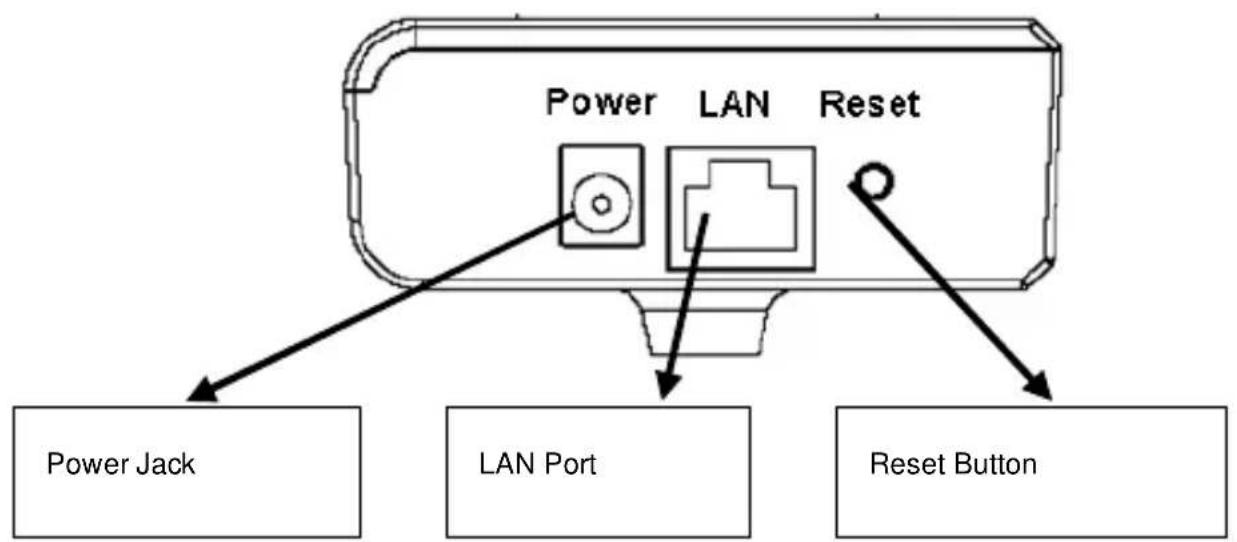
The Camera features three ports and a Reset button.
ü Power
The Power port is where you can connect the power adapter.
ü LAN
The LAN port is where you can connect the Ethernet network cable.
ü WLAN (Antenna Connector)
This round connection is standard Reverse SMA connector where any antennas with Reverse SMA connector can connect to the Internet Camera..
ü Reset
-
If problems occur with your Internet Camera, press the reset button with a pencil tip (for less than 2 seconds) and the Internet Camera will re-boot itself, keeping your original configurations.
-
If problems persist or you experience extreme problems or you forgot your password, press the reset button for longer than 5 seconds and the Internet Camera will reset itself to the factory
default settings (warning: your original configurations will be replaced with the factory default settings).
text_image
Power LAN Reset Power Jack LAN Port Reset ButtonInstallation Procedure
- Unpack the Internet Camera package and verify that all the items listed in the Chapter 2 are provided.
- Connect the Internet Camera to your network by attached the network cable from the switch/router to the UTP port of the Internet Camera.
- Connect the power adapter to the Internet Camera and plug the power adapter to power outlet. The Internet Camera will be powered on. When the Internet Camera is ready, the Ready LED will light.
- Make sure that you have installed correct VGA driver and DirectX 9.0 or above.
Note: It is highly recommended to use the power adapter shipped with the Internet Camera, do NOT use any other power adapter from any sources.
Software Installation
Follow the simple steps below to run the Install Wizard to guide you quickly through the Installation process. The following installation is implemented in Windows XP. The installation procedures in Windows 2000/Server 2003 are similar.
-
Insert the CD shipped along with the Internet Camera into your CD-ROM drive. The “Autorun.exe” program should be executed automatically. If not, run “Autorun.exe” manually from “Autorun” folder in the CD.
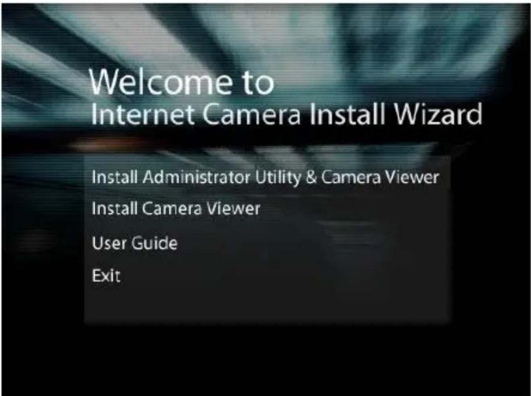
-
The Install Wizard will show four selections, select the program you want to install or click “Exit” to install the program later. The following installation steps are the demonstration of “Install Administrator Utility & Camera Viewer”.
text_image
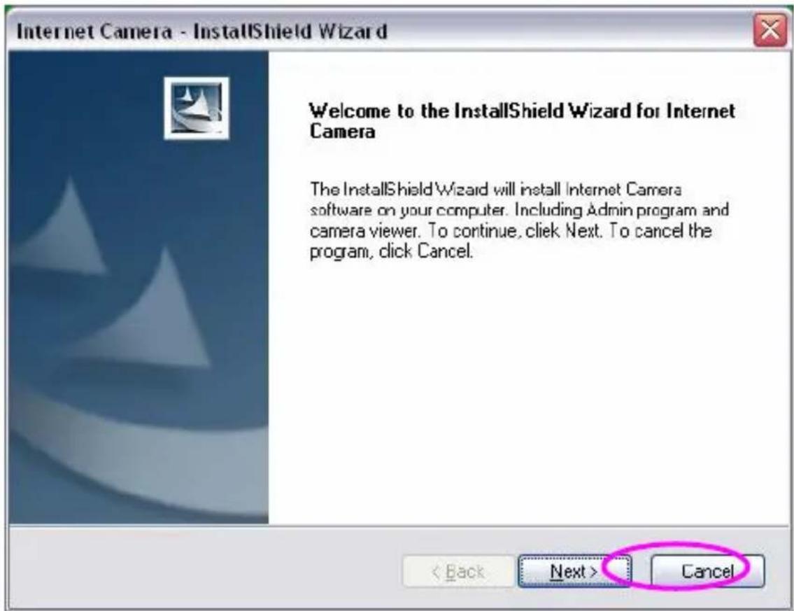
Welcome to Internet Camera Install Wizard Install Administrator Utility & Camera Viewer Install Camera Viewer User Guide Exit- The system will start the installation procedures. Click "Next" to continue installation.
text_image
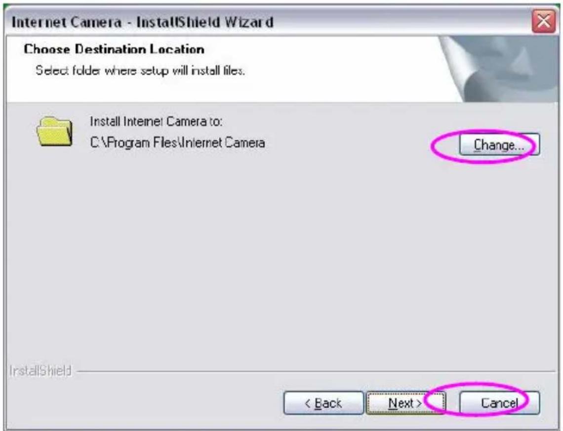
Internet Camera - InstallShield Wizard Welcome to the InstallShield Wizard for Internet Camera The InstallShield Wizard will install Internet Camera software on your computer. Including Admin program and camera viewer. To continue, click Next. To cancel the program, click Cancel. < Back Next > Cancel- If you wish to install the software program in an alternate location, click "Change"; otherwise click "Next" to move on to the next step.
text_image
Internet Camera - InstallShield Wizard Choose Destination Location Select folder where setup will install files. Install Internet Camera to: C:\Program Files\Internet Camera Change... InstallShield < Back Next > Cancel- Click "Install" to start installing the program.

text_image
Internet Camera - InstallShield Wizard Ready to Install the Program The wizard is ready to begin installation. Click Install to begin the installation. If you want to review or change any of your installation settings, click Back. Click Cancel to exit the wizard InstallShield < Back Install Cancel- The system will install the program automatically.
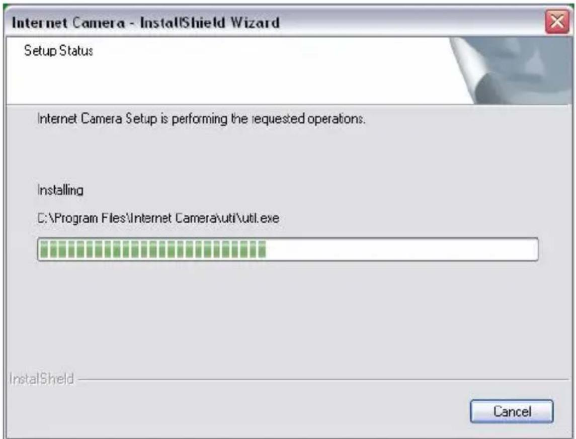
text_image
Internet Camera - InstallShield Wizard Setup Status Internet Camera Setup is performing the requested operations. Installing C:\Program Files\Internet Camera\util\util.exe InstallShield Cancel- Click "Finish" to complete the software installation.

text_image
Internet Camera - InstallShield Wizard InstallShield Wizard Complete The InstallShield Wizard has successfully installed Internet Camera software. Click Finish to exit the wizard. < Back Finish Cancel- "Administrator Utility" will be run automatically after installation. On the Internet Camera first page, the cameras found in the network are listed in the left window. Choose the one you want to configure and click "Setting Wizard" to proceed.
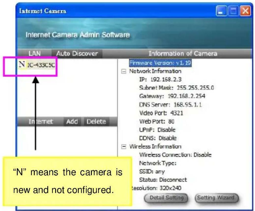
text_image
Internet Camera Internet Camera Admin Software LAN Auto Discover Information of Camera N IC-433C5C Firmware Version: v1.19 Network Information IP: 192.168.2.3 Subnet Mask: 255.255.255.0 Gateway: 192.168.2.254 DNS Server: 168.95.1.1 Video Port: 4321 Web Port: 80 UPnP: Disable DDNS: Disable Wireless Information Wireless Connection: Disable Network Type: SSID: any Status: Disconnect Resolution: 320x240 Detail Setting Setting Wizard. Internet Add Delete "N" means the camera is new and not configured.- Please enter the default password "1234" and click "OK" to login to the IP setup page.

text_image
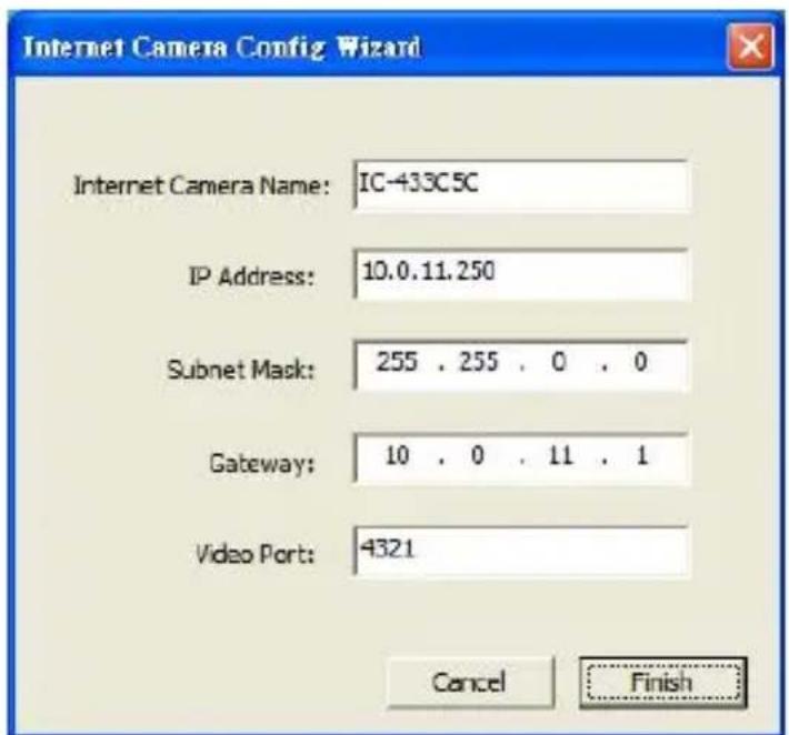
Input the Password Name: admin Password: OK- Internet Camera is working through the network (TCP/IP Protocol). The IP address and subnet mask setting must be correct, or you cannot access to the camera. The wizard program will detect the IP address status of your network automatically and suggest a free IP address for the Camera. You can accept the suggested value or enter the value manually. If you enter the value manually, please be aware that the “Subnet Mask” must be the same for both the camera and the PC. Click “Finish” to apply the configuration.

text_image
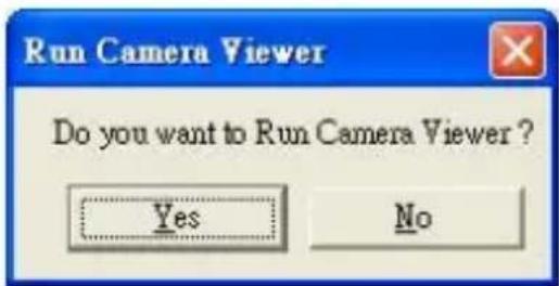
Internet Camera Config Wizard Internet Camera Name: IC-433C5C IP Address: 10.0.11.250 Subnet Mask: 255 . 255 . 0 . 0 Gateway: 10 . 0 . 11 . 1 Video Port: 4321 Cancel Finish- This wizard will pop up a window to ask you if you want to run the "Camera Viewer" and see the video of the Camera immediately. Select "OK" to run "Camera Viewer".

text_image
Run Camera Viewer Do you want to Run Camera Viewer ? Yes No- The "Camera Viewer" will show the video automatically.
Congratulations, you can use the camera through the network to view the video from now on.

Using the Administrator Utility
The Administrator Utility allows users to search and setup the cameras located within the Intranet or on the Internet. From the utility, users can view all the information of the selected camera; furthermore, it provides a setting wizard, which can guide users to add the camera to the network easily and promptly.
There are two ways to run the Administrator Utility as follows.
-
Click "Start", select "Programs\IP Camera\Admin Utility" to run the utility.
-
Double click the "IP Camera Admin" icon to run the utility.
Once the utility is started, it will search all the cameras within the network. To do more settings, please refer to the description in the following sections.

text_image
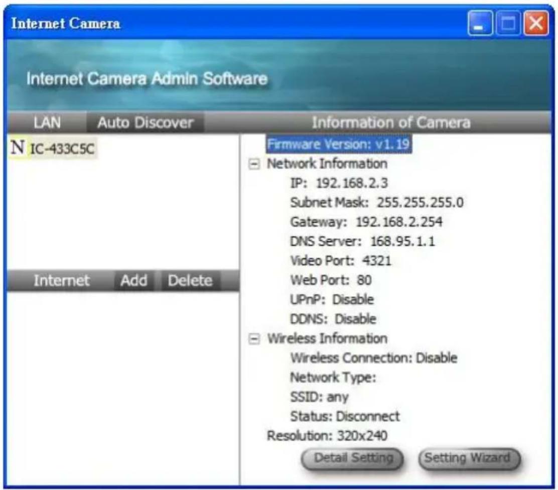
Internet Camera Internet Camera Admin Software LAN Auto Discover Information of Camera N IC-433C5C Internet Add Delete Firmware Version: v1.19 ■ Network Information IP: 192.168.2.3 Subnet Mask: 255.255.255.0 Gateway: 192.168.2.254 DNS Server: 168.95.1.1 Video Port: 4321 Web Port: 80 UPnP: Disable DDNS: Disable ■ Wireless Information Wireless Connection: Disable Network Type: SSID: any Status: Disconnect Resolution: 320x240 Detail Setting Setting WizardGeneral Setting
text_image
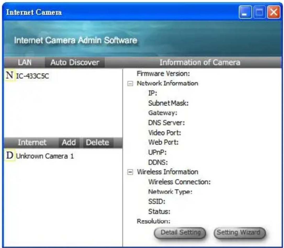
Internet Camera Internet Camera Admin Software LAN Auto Discover Information of Camera N IC-433C5C Internet Add Delete D Unknown Camera 1 Firmware Version: ■ Network Information IP: Subnet Mask: Gateway: DNS Server: Video Port: Web Port: UPnP: DDNS: ■ Wireless Information Wireless Connection: Network Type: SSID: Status: Resolution: Detail Setting Setting WizardLAN
Auto Discover
Click the button will search the camera within the network.
Camera List
The list shows the camera name and the setup status of the camera.
N It means the camera is in the default setting.
□ It means the camera is configured before.
Internet
Add Click "Add" will appear a window for you to enter the IP Address of the camera on the Internet.
Delete Click "Delete" to delete the camera from the list.
Camera List The list shows the camera name and the connect status of the camera.
D Unknown Camera 1 It means the camera is disconnected or not in the Internet.
M It means the camera is connected.
Information of Camera
Camera Information It displays all information of the selected camera. The information includes Firmware Version, Network Information, IP Address, UPnP Setting, DDNS Setting, Resolution and E-mail setting, etc.
Camera Setting

natural_image
Abstract logo design featuring a stylized geometric shape with a 'GE' text, no readable text or symbols beyond the logo itself.GEMBIRD®
IP camera
Detail Setting
Click “Detail Setting” to do more setting of the camera such as IP address, Resolution, password and firmware upgrade, etc.
Setting Wizard
Click "Setting Wizard" to setup the necessary setting for the camera.
Detail Setting
When you click the “Detail Setting”, a screen will pop up for you to enter the “Administrator Name” and “Password”. The default value is as follows.
Name: "admin"
Password: "1234"
text_image
Internet Camera Internet Camera Admin Software LAN Auto Discover Information of Camera N IC-433C5C Internet Add Delete Firmware Version: v1.19 Network Information IP: 192.168.2.3 Subnet Mask: 255.255.255.0 Gateway: 192.168.2.254 DNS Server: 168.95.1.1 Video Port: 4321 Web Port: 80 UPnP: Disable DDNS: Disable Wireless Information Wireless Connection: Disable Network Type: SSID: any Status: Disconnect Resolution: 320x240 Detail Setting Setting Wizard
text_image
Input the Password Name: admin Password: | OKIf the name and password you enter are correct, you can start to setup the camera.
Network Setting

text_image
Edit Internet Camera Network Settings | Wireless Settings | E-Mail Settings | PPPoE Setti | DHCP : ○ Enable ○ Disable Camera Name: IC-433C5C IP Address: 10 . 0 . 11 . 250 Subnet Mask: 255 . 255 . 0 . 0 Gateway: 10 . 0 . 11 . 1 DNS Server: 168 . 95 . 1 . 1 Video Port: 4321 Web Port: 80 Cancel OKNetwork Setting
Internet Name
Camera The default camera name is “IC1500WG”. It is recommended to name a meaningful name for the camera.
| IP Address | Enter an unused IP Address within the IP address range used on your LAN. If the IP Address of your LAN is from the 192.168.2.1 to 192.168.2.254, you can set an unused IP Address from the range for the camera, for example: 192.168.2.250. |
| Subnet Mask | The Subnet Mask field must match the subnet setting on your LAN. For example: 255.255.255.0. |
| Gateway | The Gateway is used to forward frames to destinations in a different subnet on the Internet. The Gateway setting must be the same with the gateway used by the PCs on your LAN. |
| DNS Server | DNS Server (Domain Name Server) that translates names to IP addresses. Set the same DNS Server as the PCs on your LAN. |
Network Setting
Video Port The Video Port is used to transmit or receive the video streaming in the network. The default port setting is
“4321”. If you want to view the video from the camera, the port setting should be correct.
Web Port
This camera support web connection, the default web port is 80. Since the web server may use port 80, you can use a different port for the camera. If you change the web port from 80 to 8080, you must type http://192.168.2.3:8080 to connect the camera through the web browser.
Wireless Settings (\* Wireless Model Only)

text_image
Edit Internet Camera Network Settings Wireless Settings E-Mail Settings PPPoE Settings FTP Settings Date / Time Settings Resolut Wireless Connection Enable Disable Available Network SSID Signal GF_EMAX MEDIUM Refresh Connect Add to Profile Profile List Profile N... SSID Channel Network ... Encryption Add Edit Delete Activate Network Information Network Type SSID Channel BSSID Encryption Signal Strength Cancel OKUtility will site survey automatically or you can press "Refresh" button to survey the AP router manually.
text_image
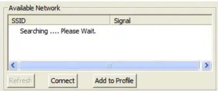
Available Network SSID Signal Searching .... Please Wait. Refresh Connect Add to ProfileAfter site survey procedure, there will show existing AP SSID.

text_image
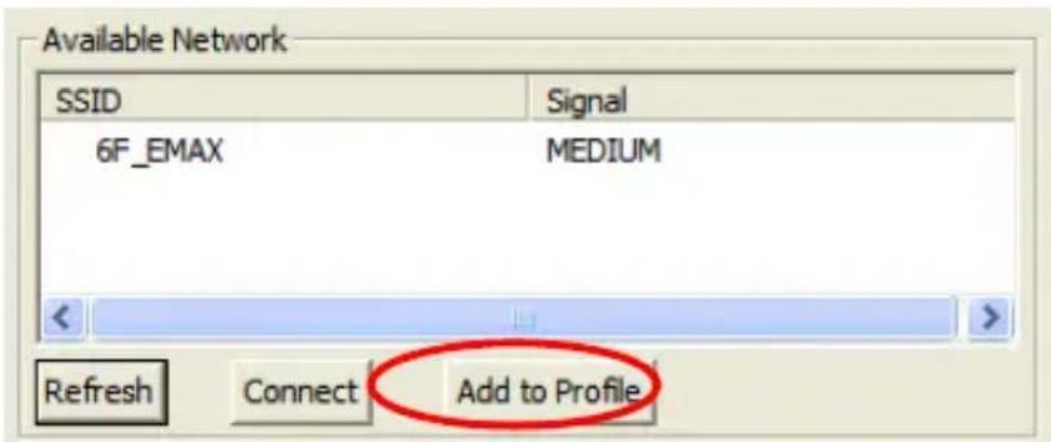
Available Network SSID Signal 6F_EMAX MEDIUM Refresh Connect Add to ProfileThen press “Connect” to connect AP router or press “Add to Profile” to configure the Wireless
WEP and WPA encryption.
text_image
Available Network SSID Signal 6F_EMAX MEDIUM Refresh Connect Add to Profile
text_image
Edit Profile Profile Name Profile_1 SSID GF_EMAX Channel 11 Network Type Infrastructure Ad Hoc Authentication Type None Encryption Type None WPA Pre-Shared Key Open System WPA Pre-Shared Key Shared Key WPA Pre-Shared Key WPA-PSK WPA Pre-Shared Key WPA2-PSK Key Length WPANone Key Format HEX ASOT Default Key(Key 1) Key 1 Key 2 Key 3 Key 4 OK CancelThere are WEP(Open System/Shared Key), WPA-PSK, WPA2-PSK and WPANone encryption settings. You can choose one to match AP router wireless settings.
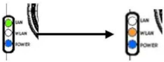
After set the profile, Please remove the LAN cable then IP Camera will connect to AP router automatically.
text_image
LAN WLAN POWER LAN WLAN POWERLED Status Diagram

text_image
GEMBIRD®IP camera
flowchart
graph TD
    A["Internet"] --> B["AP Router"]
    B --> C["Laptop"]
    B --> D["Switch"]
    B --> E["Ground"]
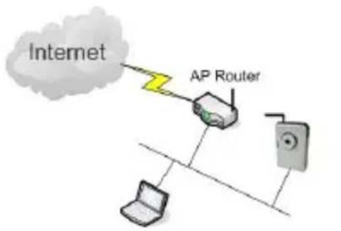
Wired Setting Environment
flowchart
graph TD
    A["Internet"] --> B["AP Router"]
    B --> C["Laptop"]
    B --> D["Power Out"]
    style A fill:#ccc,stroke:#333
    style B fill:#999,stroke:#333
    style C fill:#ccc,stroke:#333
    style D fill:#ccc,stroke:#333
Wireless Setting Environment
You must configure the wireless settings from wired environment. Then you can remove the wired cable and start wireless connection.
E-Mail Setting

text_image
Edit Internet Camera Network Settings | Wireless Settings | E-Mail Settings | PPPoE Sett Send a Test Email Recipient E-Mail Address: SMTP Server: Sender E-Mail Address: SMTP Authentication: ○ Enable ○ Disable Username: Password: Cancel OKE-Mail Setting
Recipient E-Mail Address This camera supports “Snap Shot” and “Motion Detection” functions. You can snapshot a picture and send the picture by E-Mail. Enter the E-Mail Account for receiving the picture.
SMTP Server
Enter the SMTP Server for the E-Mail sending.
Sender E-Mail Address
Specified the e-mail address of the e-mail sender.
| Authentication | Enable or Disable the SMTP Authentication function |
| Username | When Authentication is enabled, input the SMTP Username. |
| Password | When Authentication is enabled, input the password. |
| Send a Test Email | Press this button to send a test e-mail to your mailbox. You can use this function to test if your setting is correct. |
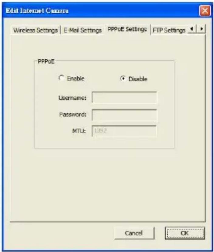
PPPoE Settings
text_image
Edit Internet Camera Wireless Settings | E-Mail Settings | PPPoE Settings | FTP Settings | -PPPoE Enable Disable Username: Password: MTU: 1352 Cancel OKPPPoE Settings
Enable/Disable
If enable the PPPoE function, IP Camera will use PPPoE for network connection first. The default value is “Disable”.
Username
Enter the Username of PPPoE connection.
Password
Enter the Password of PPPoE connection
MTU
A maximum transmission unit (MTU) is the
largest size packet or
frame, specified in octets (eight-bit bytes), that can be sent in a
packet or frame based network such as the Internet.
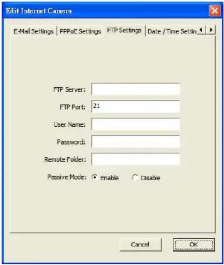
FTP Settings
text_image
Edit Internet Camera E-Mail Settings | PPPoE Settings | FTP Settings | Date / Time Settin | FTP Server: FTP Port: 21 User Name: Password: Remote Folder: Passive Mode: ○ Enable ○ Disable Cancel OKFTP Settings
| FTP Server | This camera supports “Motion Detection” functions. When Motion Detection event occurred, you can record the pictures to FTP server. Enter the FTP address for receiving the pictures. |
| FTP Port | Enter the port of the FTP server. |
| User Name | Specify the user account of ftp server. |
| Password | Specify the Password of your ftp account. |
| Remote Folder | Specify the folder of the ftp site that you want to store the video. |
| Passive Mode | If your Camera is under NAT, you usually need to enable this feature. |
Date / Time Settings

text_image
Edit Internet Camera PPPoE Settings | FTP Settings | Date / Time Settings | Resolution | Set Date/Time manually 2007/ 1/10 下午 07:37:42 NTP Server Time Zone : (GMT+05:00) Telpe NTP Server : pool.ntp.org Cancel OKDate / Time Settings
Set Date/Time Set the current Date and Time.
manually
NTP Server Synchronize the Date and Time with NTP server.
Time Zone Select the time zone that your camera put on.
NTP Server Specify the IP Address of the NTP Server.
Resolution

text_image
Edit Internet Cameras Date / Time Settings Resolution Advanced Settings Users Tc Resolution: 160x120 160x120 320x240 640x460 Cancel OKResolution
Resolution
Select the desired video resolution format. Larger resolution requires more bandwidth. 640 x 480 is “VGA” format. 320 x 240 is “QVGA” format. 160 x 120 is “QQVGA” format.
Advanced Setting

text_image
Edit Internet Camera Date / Time Settings | Resolution | Advanced Settings | Users | Tc | UPnP Enable Disable DONS Enable Disable Provider: DynDNS Domain Name: ddns-host Account: ddns-account Password: ********** Cancel OKAdvanced Setting
UPnP
When the UPnP function is enabled, the camera can be detected by UPnP compliant system such as Windows XP. The camera will be displayed in the Neighborhood of Windows XP, so you can directly click the camera to view the video through web browser.
DDNS
Many internet connections use a "Dynamic IP address", where the Internet IP address is allocated dynamically whenever the Internet connection is established. Internet users should know the IP Address of the camera when they want to connect to the camera every time. DDNS is designed to solve this problem, by allowing users to connect to your LAN using a domain name, rather than an IP address.
Enable/Disable
Enable or disable DDNS function of the camera.
Provider
Several companies provide DDNS service. This camera supports the service from DynDNS who is one of the DDNS providers.
Domain Name
The domain name given by DynDNS is "registername.dyndns.com". Enter the domain name that you register for the camera from DynDNS web site.
Account
Enter the login name for the DDNS service.
Password
Enter the password for the DDNS service.
Users

text_image
Edit Internet Camera Date / Time Settings | Resolution | Advanced Settings | Users | Tools | About | Administrator Login Name: Admin New Password: Current Password: Confirm New Password: User User Account 1 User Account 2 User Account 3 User Account 4 User Name Password Confirm Password Cancel OKUsers
Administrator
Setting the password of Administrator account
Current Password
Enter the current password of the camera.
New Password
Enter the new password you want to use for the camera.
Confirm New Password Retype the new password to confirm the setting.
User Setting the user account and password. Your camera can support 4 user account.
Tools

text_image
Edit Internet Camera Resolution | Advanced Settings | Users | Tools | About | Firmware Version: v1.19 Firmware Update Reset to Default LED Light OFF Cancel OKTools
Firmware Version
Display current firmware version.
Firmware Update
You can upgrade camera's firmware via this function. Press this button and select the correct firmware to upgrade.
Reset to Default
If you want to reset the camera, click this button.
The default settings of the camera are as follows.
Camera Name: "IC-XXXXXX"
IP Address: "192.168.2.3"
Subnet Mask: 255.255.255.0
Administrator Name: "admin"
Password: "1234"
Video Port: "4321"
Web Port: "80"
LED Light Off
Press this button can turn off LAN and WLAN LED.
But can not turn off Power LED.
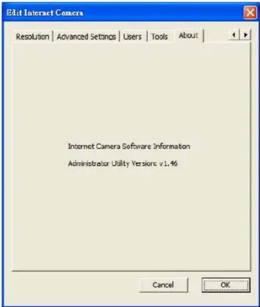
About
text_image
Edit Internet Camera Resolution | Advanced Settings | Users | Tools | About | Internet Camera Software Information Administrator Utility Version: v1.46 Cancel OKAbout
Administrator
Version
Utility Display current Administrator Utility Version.
Setting Wizard
When you click the “Setting Wizard”, a screen will pop up for you to enter the “Administrator Name” and “Password”. The default value is as follows.
Name: "admin"
Password: "1234"

text_image
Input the Password Name: admin Password:If the name and password you enter are correct, you can start to setup the camera.
text_image
Internet Camera Config Wizard Internet Camera Name: IC-433C5C IP Address: 10.0.11.250 Subnet Mask: 255 . 255 . 0 . 0 Gateway: 10 . 0 . 11 . 1 Video Port: 4321 Cancel FinishInternet Camera The default camera name is "IC-XXXXXX". It is Name recommended to enter a meaningful name for the camera.
IP Address The wizard will auto setup an available IP Address to the camera. For example: if the IP address of the network is 192.168.2.x, the wizard will search an unused IP Address from 192.168.2.1 to 192.168.2.250 and assign the camera an available IP Address.
You are allowed to enter another IP Address to change the setting.
Subnet Mask The wizard will auto search the Subnet Mask setting of the network and set the camera in the same Subnet Mask.
You can enter another Subnet Mask to change the setting.
Gateway The wizard will auto search the Gateway setting of
| the network and set the camera to use the same Gateway. | |
| You can enter another Gateway to change the setting. | |
| Video Port | It defines the video stream port. The default value is “4321”. |
| Cancel | Click “Cancel” to stop wizard setting. |
| Finish | Click “Finish” to complete the camera setting. |
text_image
Run Camera Viewer Do you want to Run Camera Viewer ? Yes NoWhen you finish the camera setting, you can click "Ok" to run the "Camera Viewer" immediately or click "Cancel" to run the "Camera Viewer" later.
Using the Camera Viewer
The Camera Viewer Utility allows users to view video up to four cameras. It also allows users to manual/schedule recording video and playback the video file. The status of camera viewing such as frame rate, video received, and etc. are also recorded in time.
There are three ways to run the Camera Viewer Utility as follows.
- Click "Start", select "Programs\IP Camera\Camera Viewer" to run the utility.
- Double click the "IP Camera Viewer" icon to run the utility.
- Click "Setting Wizard" from Administrator Utility and follow the instructions in the utility.
Panel Introduction
In the beginning when you start the Camera Viewer, you would see a Control Panel and a four division Viewer window.

text_image
Camera Viewer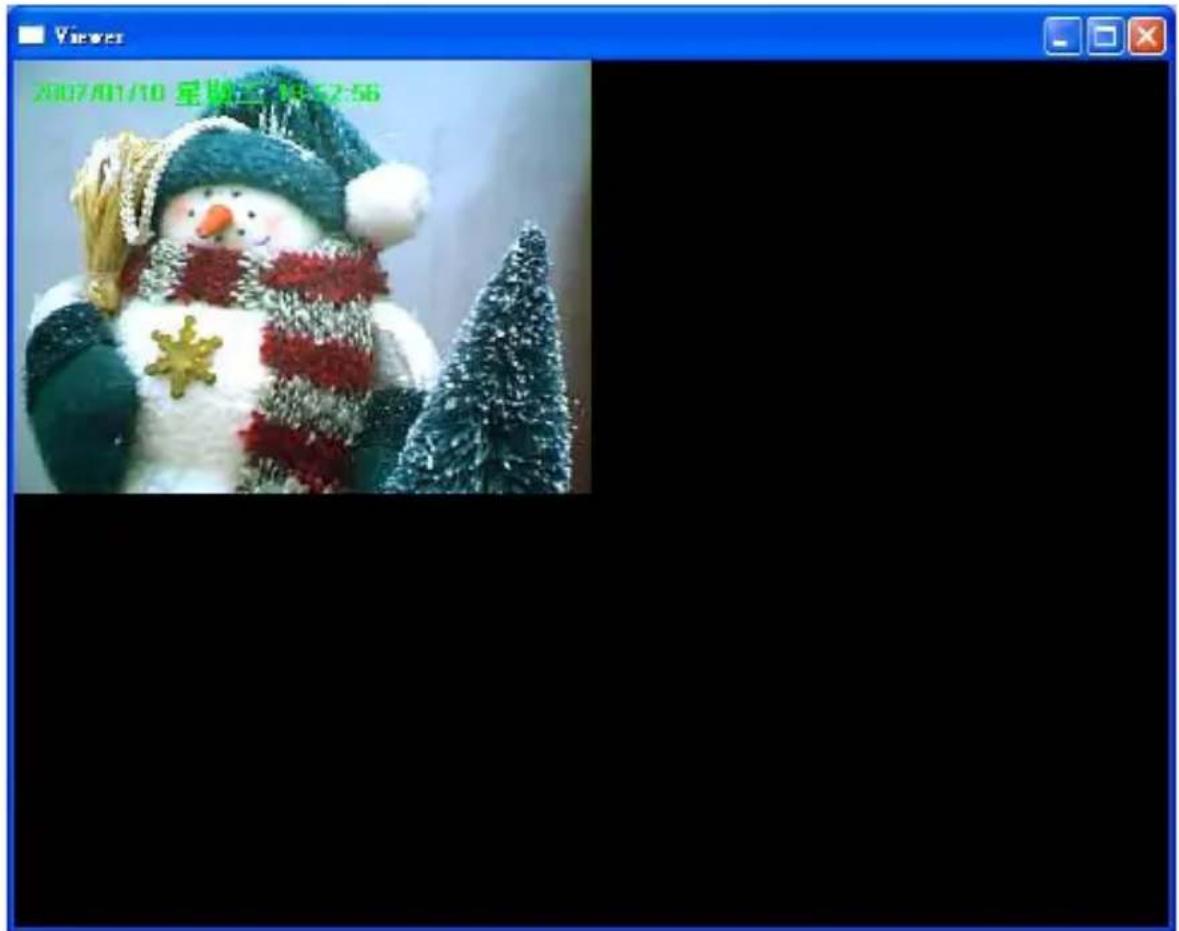
text_image
Camera Viewer
text_image
Camera Viewer Reset Camera 1 Configure Camera 1Camera Buttons
Camera


Click one of these four cameras will connect to the selected camera that you want to view and configure. If you want to remove the camera from the viewer, please right click the icon and select "Reset Camera x". If you want to configure the camera, please right click the icon and select "Configure Camera x".
Camera Status
There is a status bar shown different color to indicate the status of each Internet Camera.

text_image
Camera ViewerCamera Status
| Yellow | It means that there is no camera set to connect. |
| Blue | It means that the camera is connected and playing the live video. |
| Pink | It means that the camera is not connected now. |
| Red | It means that the camera is recording. |
Control Buttons
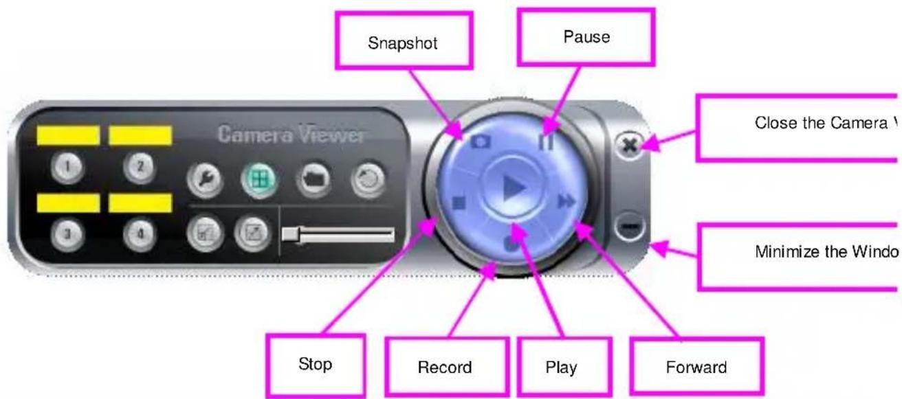
text_image
Snapshot Pause Close the Camera V Minimize the Windo Stop Record Play ForwardControl Buttons
Play

The “Play” button is an intelligent play user-interface. In the normal display mode and the Internet Camera is disconnected, clicking on the “Play” can make the viewer connect to the Internet Camera. In the playback mode, clicking on the “Play” can play the video in the normal speed.
Stop

The “Stop” button is an intelligent play user-interface. In the normal display mode and the Internet Camera is connected, clicking on the “Stop” can make the viewer disconnect the
camera. In the playback mode, clicking on the "Stop" can stop playing the video.
Pause

The “Pause” button provides you a way to pause the current video display. When the displaying video is paused, click on the “Play” again to resume the video display.
Forward

The “Forward” button to forward the speed of display when playback the recording file. Click the button at a time will increase the playing speed one time.
Snapshot

Click “Snapshot” will make the viewer to take a snapshot of the video and save the picture as a bitmap file in the hard disk. (You can set the directory for storing these bitmap files at the Section 7.8.4)
Record

By clicking “Record” you can record video immediately. (You can set the directory for storing video files at the section 7.8.4)
Pan-Tilt Control Panel
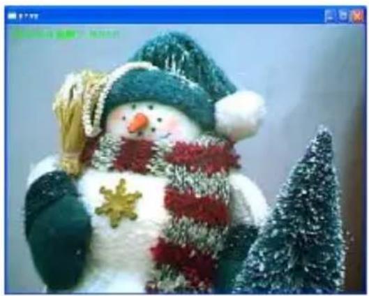
When you can see the video image on screen and click on
The viewer will show only one camera video and appear the Pan-Tilt control panel.

natural_image
Fluffy snowman wearing green hat and red scarf, decorated with Christmas tree (no text or symbols visible)#
natural_image
Festive snowman dressed in winter clothing with a Christmas tree nearby (no text or symbols visible)
text_image
Camera Viewer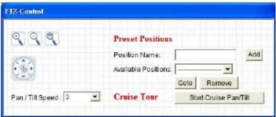
text_image
PTZ Control Preset Positions Position Name: Add Available Positions: Go to Remove Pan / Tilt Speed : 3 Cruise Tour Start Cruise Pan/Tilt
text_image
GEMBIRD®IP camera

natural_image
Three small icons: a magnifying glass, a minus sign, and a cursor pointer with directional arrows (no text or symbols)Pan / Tilt Speed: 3
PTZ Control Panel

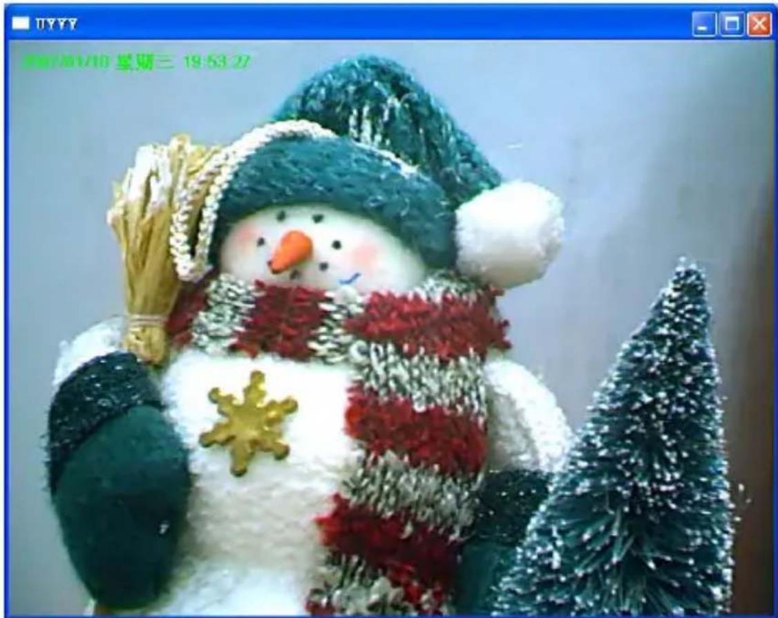
Full View
Press

button, you can see full size
image.

natural_image
Close-up of a small figurine wearing a Santa hat and scarf, with a small tree in the foreground (no text or symbols visible)‡

natural_image
Interior office scene with a decorated cake and tree, no visible text or symbols
Zoom Out
Press

button, the image will be
Zoom-Out.

natural_image
Stuffed snowman figurine wearing a hat and scarf with a star-shaped badge (no text or symbols visible)‡

natural_image
Decorative snowman figurine with a Christmas tree, no text or symbols visible
Zoom In
Press

button, the image will be
Zoom-IN.

natural_image
Decorative snowman figurine with green hat and snowflake, accompanied by a small Christmas tree (no text or symbols)‡

natural_image
Close-up of a snowman wearing a green hat and striped scarf with a flower (no text or symbols visible)
Direction Panel
There are 8 directions of control panel. You can control Left-Right, Up-Down by this panel.
Pan / Tilt Speed
You can adjust Pan / Tilt moving speed from 1(Slow) to 5(Fast).
Preset Positions
Position Name:
Available Positions:

text_image
Add Goto RemovePreset Position
Position Name
You can add name to locate position. Like Windows, Door or other easy words.
Available Position
You can check and see the existing position record here.
Add After you named the position name, you can press to store the preset position.
Goto After you select an existing position and click Goto, the screen will go to the selection preset position immediately.
Remove If you want to remove preset position, you can select the existing preset position and click Remove
* Notice: After you set the preset positions, you must enter Web Management Page to set Guard Tour function in PTZ menu (See 8.2 PTZ Settings).

flowchart
graph TD
    A["Start Cruise Pan/Tilt"] --> B["Cruise Tour Path"]
    B --> C["Apply"]
    B --> D["Plan/tilt Option"]
    D --> E["Next Step"]
    style A fill:#f9f,stroke:#333
    style B fill:#ccf,stroke:#333
    style C fill:#cfc,stroke:#333
    style D fill:#fcc,stroke:#333
    style E fill:#ffc,stroke:#333
Cruise Tour
Start Cruise Pan/Tilt Cruise Tour will follow Cruise Tour Path to start cruise.
After press Start Cruise Pan/Tilt, the original button will become Stop Cruise Pan/Tilt.
Stop Cruise Pan/Tilt Press Stop Cruise Pan/Tilt can stop Cruise Tour then the original button will become
Start Cruise Pan/Tilt
* Notice: You must enter Web Management Page to set Cruise Tour Path in PTZ menu.
Video Recording
This utility allows you record the video in AVI files. There are two ways of video recording – Manual Recording and Schedule Recording.
Manual Recording
You can manually record the video stream into an assigned video file. Click "Record", then the viewer utility will start to record the video stream. You can assign the path in the setting dialog.(at section 7.8.4) Clicking "Stop" will stop recording.
Note: Before manual recording, you have to click the camera button to select the Internet Camera that you want to record first and make sure that the viewer is successfully connecting to the Internet Camera.
Schedule Recording
You can assign a schedule and let this viewer automatically recording the video stream. Please refer to Section 7.8 to see how to setup schedule for the recording. The file name of the recorded video file is the start time of recording. For example, the file name "IPCamera_2004-10-8-23-56-40.avi" means it was recorded at 2004/10/8 23:56:40.
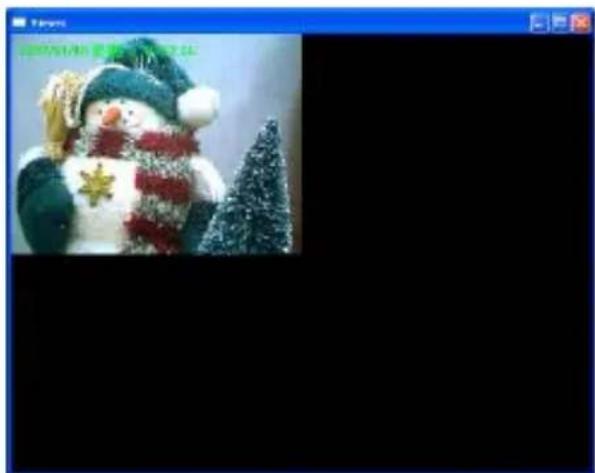
Change Resolution
The Internet Camera supports two resolution, 640x480 (VGA) and 320x240 (CIF). You can change the resolution of each Internet Camera by clicking the resolution button.
Note: Before changing the resolution of the Internet Camera, you have to select the Internet Camera by clicking the camera button first. If you change the resolution of an Internet Camera, other clients who are viewing the same Internet Camera simultaneously will also see the video with the changed resolution, too.
natural_image
Festive snowman dressed in winter clothing with a Christmas tree, no visible text or symbolsResolution
VGA
Change the resolution to 640x480 (VGA) mode.

QVGA
Change the resolution to 320x240 (QVGA) mode.

View Four Cameras Simultaneously
Click the four division button can view the 4 cameras simultaneously in a four-division window.

natural_image
Illustration of a snowman wearing a green hat and scarf, standing beside a Christmas tree (no text or symbols visible)Viewer Utility Setting
Click the "Setting" button Camera will pop up.

, then the setting window of the Internet Note: When you want to change the settings such as IP Address, Video Port, etc. in the “Setting” option, you must disconnect the Internet Camera first by clicking the “Stop”.
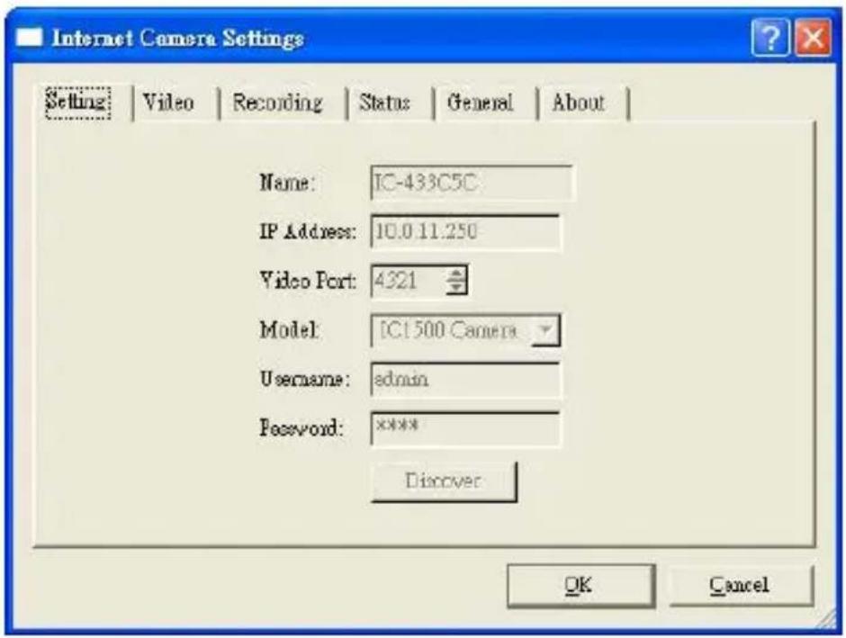
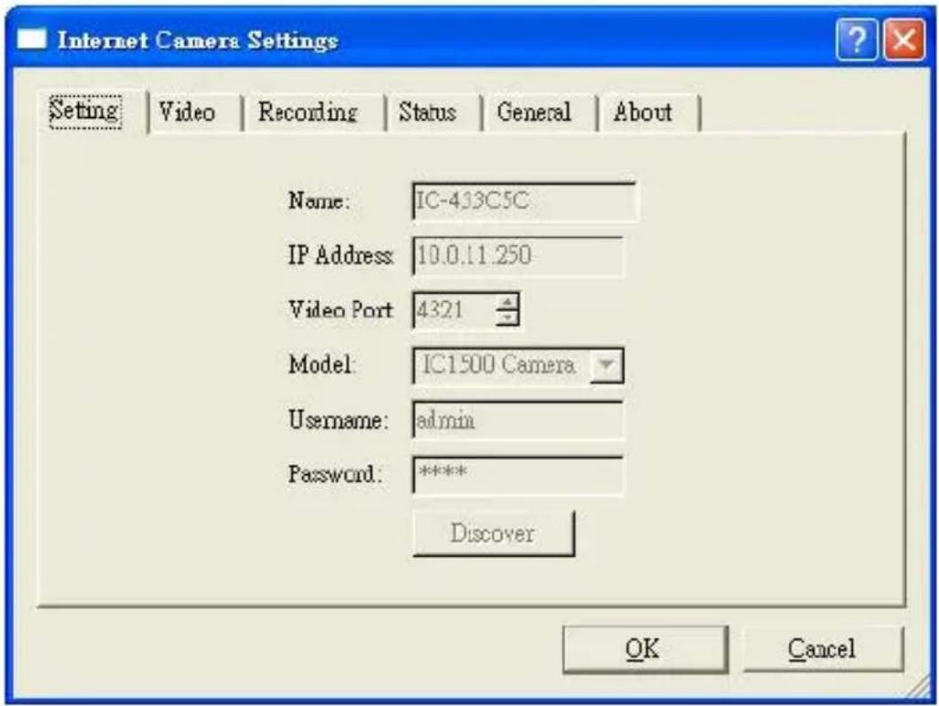
text_image
Internet Camera Settings Setting | Video | Recording | Status | General | About | Name: IC-433C5C IP Address: 10.0.11.250 Video Port: 4321 Model: ICI 500 Camera Username: admin Password: ***** Discover OK CancelSetting
text_image
Internet Camera Settings Setting | Video | Recording | Status | General | About | Name: IC-433C5C IP Address 10.0.11.250 Video Port 4321 Model: IC1500 Camera Username: admin Password: ***** Discover OK CancelSetting
| Name | It is not required to fill the camera name for connecting camera. It is for users to identify the camera. |
| IP Address | IP address/Domain name of the Internet Camera. |
| Video Port | The number of service port used by the Internet Camera. |
| Model | Select “Internet Camera” (This camera only supports MJPEG). |
| Username | The user name for login into the Internet Camera. By default, the user name is “Admin”. |
| Password | The password for login into the Internet Camera. By default, the password is “1234”. |
| Discover | Click “Discover”, then camera auto-discover windows will pop up. The window will show all the discovered cameras on LAN environment for you to select. |
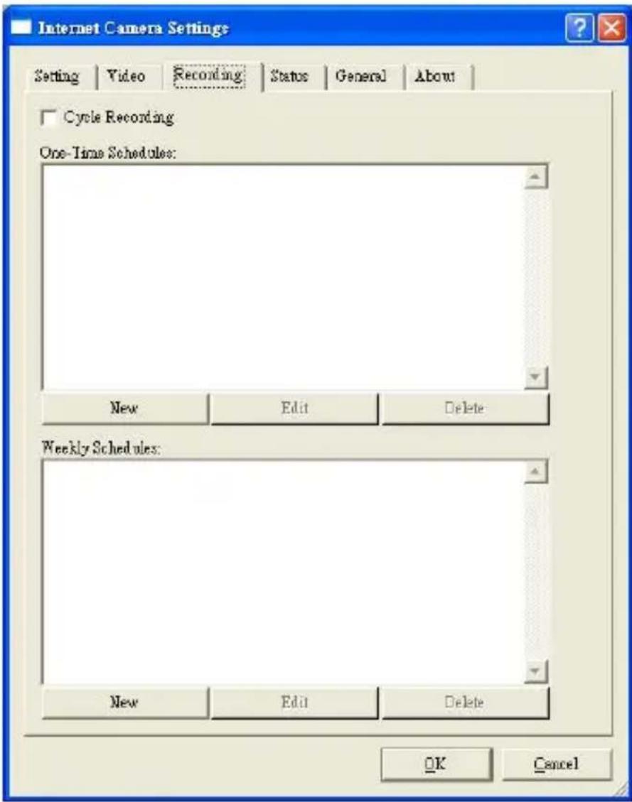
Recording
You can setup schedule for the recording here. This utility will record the video stream in the assigned file folder according to the schedule automatically. The recorded video files are AVI format.
Note:
-
The utility will only start to record the video stream when this utility is running and is successfully connecting to the Internet camera in the beginning of the schedule.
-
The schedule setting of one-time or weekly schedule should not overlap, or the recording will fail.
text_image
Internet Camera Settings Setting | Video | Recording | Status | General | About | Cycle Recording One-Time Schedules: New Edit Delete Weekly Schedules: New Edit Delete OK Cancel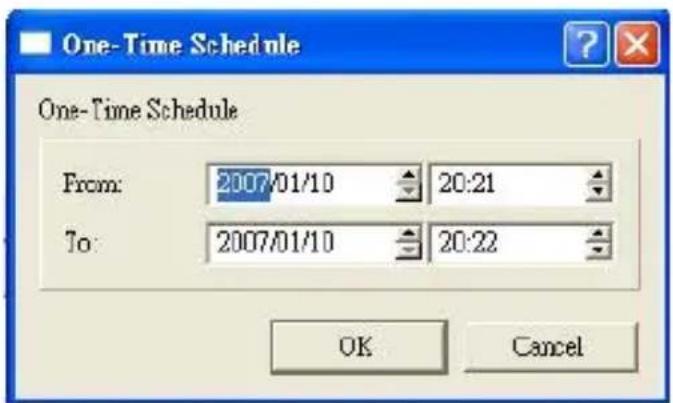
text_image
One-Time Schedule One-Time Schedule From: 2007/01/10 20:21 To: 2007/01/10 20:22 OK CancelOne-Time Schedule
text_image
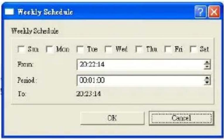
Weekly Schedule Weekly Schedule Sun Mon Tue Wed Thu Fri Sat From: 20:22:14 Period: 00:01:00 To: 20:23:14 OK CancelWeekly Schedule
Schedule
Cycle Recording
Check this check box to enable cycle recording. When the Cycle Recording is checked and the storage usage has already reached the maximum reserved storage space, the utility will automatically delete the oldest recorded video file and use the space to store the newly recorded video stream.
One-Time Schedule
You can assign a range of time and the utility will automatically record the video stream only during
| the period of time. The default time is 2 minutes later from the current time. | |
| Weekly Schedule | You can assign the days in a week and the period of time in a day when you want to record the video stream. The utility will automatically record the video stream during the periods of time every week again and again. |
Schedule
| New | Click “New” to add a new recording schedule. |
| Edit | Select an existing schedule in the schedule list and click “Edit” to edit the schedule. |
| Delete | Select an existing schedule in the schedule list and click “Delete” to delete the schedule. |
Status
You can see the current status information of the connection session between the utility and the Internet Camera.

text_image
Internet Camera Settings Setting | Video | Recording | Status | General | About | Connected: Yes Stream Started At: 19:55:41 Time Elapsed (sec): 37 Video Received (KB): 38496 Audio Received (KB): 0 Frame Rate (Frames): 15 Date Rate (KB/s): 1072 Number of Frames: 1180 Number of Users: 1 OK CancelStatus
Connected
It displays “Yes” when the utility is connecting to the Internet Camera and displays “No” when the utility is not connecting to the Internet Camera.
Status
Stream Started At
The beginning time of the current connection session between the utility and the Internet Camera.
Time Elapsed
The elapsed time of the current connection session between the utility and the Internet Camera.
Video Received
The total size (Unit is KByte) of video stream received during the current connection session between the utility and the Internet Camera.
Audio Received
The total size (Unit is KByte) of audio stream received during the current connection session between the utility and the Internet Camera. (Reserved)
Frame Rate
The frame rate (frame per second) of the current video download speed from the Internet Camera to the utility.
Data Rate
The data rate (KByte per second) of the current video download speed from the Internet Camera to the utility.

text_image
GEMBIRD®IP camera
Number of Frames
The total number of video frames received during the current connection session between the utility and the Internet Camera.
Number of Users
The total number of users that viewing this camera currently.
General
You can manage storage usage for this Internet Camera here.
text_image
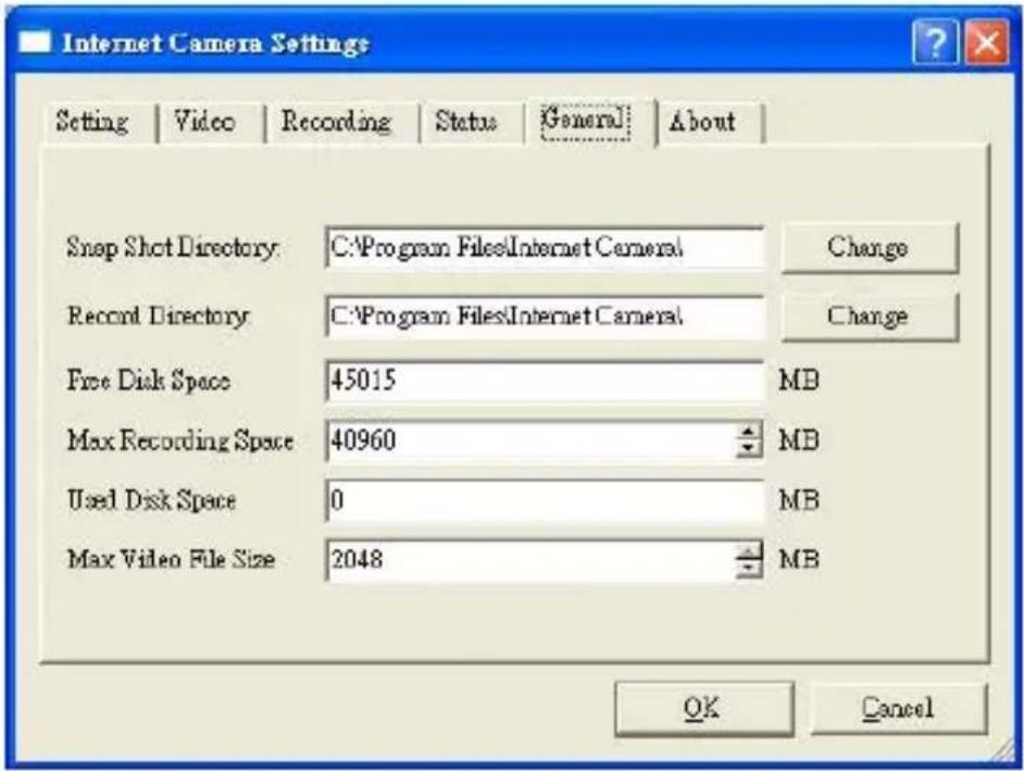
Internet Camera Settings Setting | Video | Recording | Status | General | About | Snap Shot Directory: C:\Program Files\Internet Camera1 Record Directory: C:\Program Files\Internet Camera1 Free Disk Space 45015 MB Max Recording Space 40960 MB Used Disk Space 0 MB Max Video File Size 2048 MB OK CancelGeneral
Snap Shot Directory
This lets you assign the directory where bitmap files will be stored when you click "Snapshot" to take pictures. The default folder is where the software program is installed, for example: "C:\Program Files\Internet Camera".
Record Directory
This lets you assign the directory where the recorded video files will be stored. The default folder is where the software program is installed,
for example: "C:\Program Files\Internet Camera".
Free Disk Space
The current free disk space of the hard drive where is assigned to save recording files.
Max Recording Space
You can reserve a disk space to store the recorded video and snapshot files. If the space is run out, a message will pop up to remind you.
Used Disk Space
The current used disk space for saving the recording file.
Max Video File Size
This let you assign a maximum size of each video file. The upper bound of this value is 2 GB per file.
About

text_image
Internet Camera Settings Setting | Video | Recording | Status | General | About | Internet Camera Software Information Camera Viewer Utility Version: 2.16 OK CancelAbout
Camera Viewer Utility Display current Camera Viewer Utility Version. Version
Playback
Click the “Open File” and a “Load File” window will be popped up. Select the file that you want to play.

text_image
Choose a avi file Look in: utl skino My Recent Documents Desktop My Documents My Computer My Network Places File name: Files of type: [*.evil] Open CancelThe viewer will start to play the selected video file.

natural_image
Festive snowman dressed in winter clothing with a Christmas tree, no visible text or symbolsPlaying Control
Play

When the video playback is in Stop state, just click "Play" and the viewer will play the video file from the beginning point. When the video playback is in Pause state, just click "Play" and the viewer will play the video file from the current pause point. When the viewer is playing with fast speed, just click "Play" to let the viewer play with the normal speed.
Pause

When the recorded video is playing, you can click "Pause" to freeze the playback. If you want the viewer to continue playing from the current pause point, just click "Play".
Stop

When the viewer is playing, you can click "Stop" to stop the playback. If you want the viewer to play again, just click "Play" and the viewer will play the video file from the beginning point.
Playing Control
Forward

If you want the viewer to play the video file in a faster speed when the viewer is playing the video file, just click “Forward” and the viewer will double the playing speed. If you want the viewer play with the normal speed when the viewer is playing with fast speed, just click “Play”.
Rotate Video
Rotate function lets you rotate the video frame 180 of degree angle each
time you click the “Rotate” . With this function, you can view the live video with normal, and 180 degree angles counterclockwise.
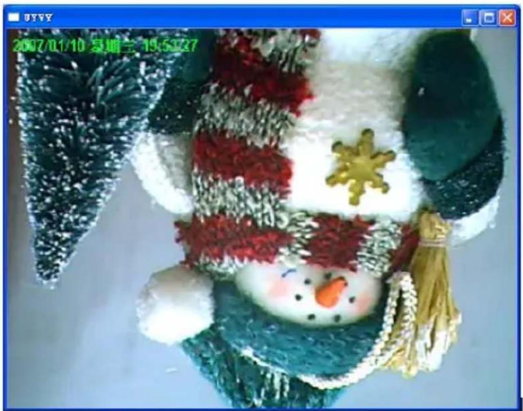
text_image
2007/01/10 春晴兰 19:53:27Web Connection and Setup
You can use the Web browser to connect the camera for viewing or setting. Open the web browser and enter the IP Address of the camera to establish a connection. The default IP Address of the camera is "192.168.2.3".
When the welcome screen appears, enter the “Admin Name” and “Password”. The default values are:
Admin Name: "admin"
Password: "1234"

text_image
Connect to 192.168.2.3 Internet Camera User name: Password: Remember my password OK CancelWhen the camera is connected, the browser will take you to the live video page. If you are viewing this camera at first time, the following dialog will appear to install the ActiveX plug in.
After installed the ActiveX plug-in, the video image will be shown up in the web screen directly.
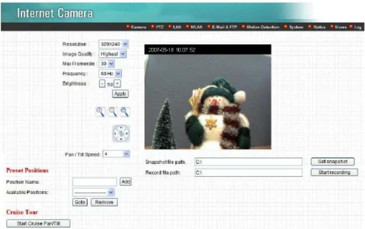
text_image
Internet Camera Resolution: 320X240 Image Quality: Highest Max Framersle: 30 Frequency: 60 Hz Brightness: -50 + Apply Pan / Tilt Speed: 4 2007-05-18 10.07.52 Preset Positions Position Name: Add Available Positions: —— Goto Remove Cruise Tour Start Cruise Pan/Tilt Snapshot file path: C:1 Record file path: C:1 Get snapshot Start recordingThe menu options for the web control screen are as follows.
Camera – View live video and adjust the video format from the menu.
PTZ – Setup the Guard Tour and Cruise Tour from the menu.
LAN – Setup the camera LAN port functions in the menu.
WLAN – Setup the camera WLAN port functions in the menu.
E-Mail & FTP – Setup the E-Mail client and FTP client in the menu.
Motion Detection – Configure the Motion Detection Actions here.
System – Setup System utilities and settings in this menu.
Status – Shows the camera information and current status in this page.
Users – This camera support up to 4 user accounts. You can setup them in this menu.
Camera Setting

text_image
Internet Camera Resolution: 320x240 Image Quality: Highest Max Framerate: 30 Frequency: 60 Hz Brightness: - 50 + Apply Pan / Tilt Speed: 4 2007-06-18 10:07:52 Preset Positions Position Name: Add Available Positions: Go to Remove Cruise Tour Start Cruise Pan/Tilt Snapshot file path: C:\ Record file path: C:\ Get snapshot Start recordingCamera Setting
Resolution
Select the desired video resolution format. Larger resolution requires more bandwidth. 640 x 480 is “VGA” format. 320 x 240 is “CIF” format. The default resolution is CIF format.
Image Quality
Adjust this property to control the video quality
Max Frame Rate
Set the video max frame rate. This camera can support at most 30 frames per second. Set the
| frame rate higher can get video more smooth. But will use more bandwidth. | |
| Frequency | Adjust this property to fitting light frequency. |
| Brightness | You can adjust the brightness of the video. If the video is too dark, you can input the larger number in this text box. The video will be brighter. This value can be from 1 to 100. |
| Pan / Tilt Speed | You can adjust Pan / Tilt moving speed from 1(Slow) to 5(Fast). |
| Apply | When you finish “AV Server” setting, click this button to validate the setting values. |

natural_image
Four icons: magnifying glass, minus sign, and zoom cap on grid background (no text or symbols)
Full View
Press image

button, you can see full size

natural_image
Close-up of a small figurine wearing a green hat and scarf, with a Christmas tree in the background (no text or symbols visible)‡

natural_image
Person holding a panda-themed object with a small tree, in an indoor setting (no visible text or symbols)
Zoom Out
Press

button, the image will be
Zoom-Out.

natural_image
Close-up of a snowman wearing a green hat and black fur, holding a flower with a yellow star (no text or symbols visible)‡

natural_image
Decorative snowman figurine with green and black patterns, accompanied by a small Christmas tree (no text or symbols visible)
Zoom In
Press

button, the image will be
Zoom-IN.

natural_image
Decorative snowman figurine with green hat and snowflake, accompanied by a Christmas tree (no text or symbols)‡

natural_image
Stylized snowman figurine with a star-shaped knot and scarf, wearing a hat and scarf (no text or symbols visible)
There are 8 directions of control panel. You can control Left-Right, Up-Down by this Direction Panel panel.
Preset Positions
Position Name:
Available Positions:

text_image
Add Goto RemovePreset Position
Position Name
You can add name to locate position. Like Windows, Door or other easy words.
Available Position
You can check and see the existing position record here.
Add
After you named the position name, you can press

to store the preset position.
Goto
After you select an existing position and
click Goto, the screen will go to the selection
preset position immediately.
Remove
If you want to remove preset position, you can select the existing preset position and
click. Remove
* After you set the preset positions, you can use Guard Tour function in PTZ menu.

text_image
Cruise Tour Path Apply Cruise Tour Start Cruise Pan/TiltCruise Tour
Start Cruise Pan/Tilt Cruise Tour will follow Cruise Tour Path to start cruise.
After press Start Cruise Pan/Tilt, the original button will become.
Stop Cruise Pan/Tilt Press Start Cruise Pan/Tilt can stop Cruise Tour then the original button will become Start Cruise Pan/Tilt.
| Snapshot file path: | C:\ | Get snapshot |
| Record file path: | C:\ | Start recording |
Snapshot / Recording
Snapshot file path You can enter the file path to store the snapshot picture.
Click Get snapshot to get one picture.
Record File path You can enter the file path to store the video image. Click Start recording to start recording. Click Stop recording to stop recording. The video format is AVI (Content Motion-JPEG), you can play the video film by Media Player.
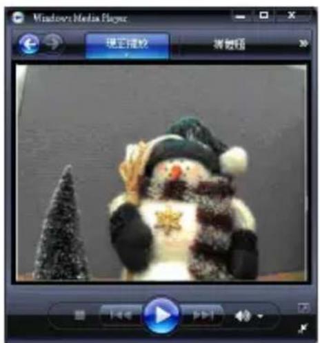
text_image
Windows Media Player 现实撞啦 新视频PTZ Setting

text_image
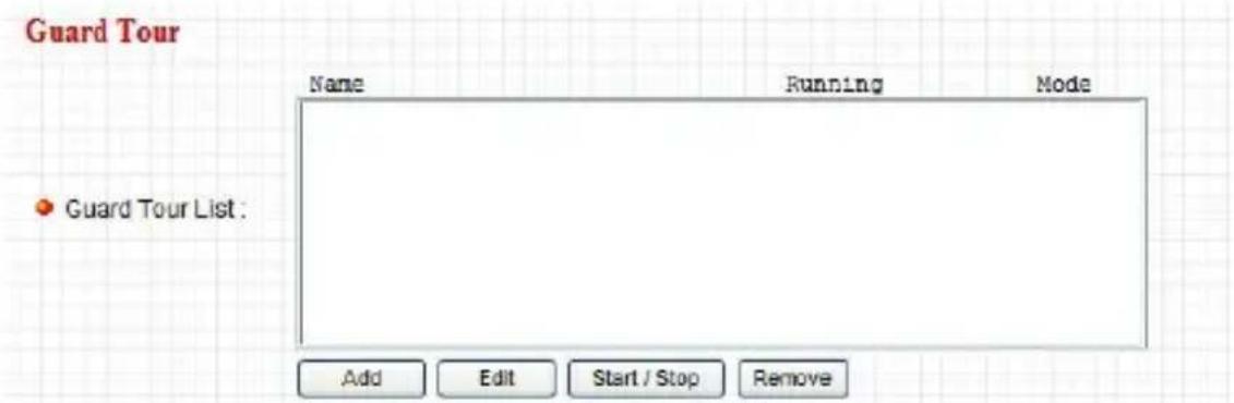
Guard Tour Name Running Mode • Guard Tour List Add Edit Start/Stop RemoveGuard Tour
Name The name of Guard Tour Name.
Running The status of Guard Tours.
No: Guard tour function is off.
Yes: Guard tour function is on.
Mode There are two modes of Guard Tour.
Sequential: Display preset position image by order.
Random: Random display preset position image.
Add Press "Add" button to create new Guard Tour.
Edit Press "Edit" button to modify the existing Guard Tour.
Start / Stop
Press "Start/Stop" button to start or stop Guard Tour.
Remove
Select existing Guard Tour then press "Remove" button to remove Guard Tour.
Setup Guard Tour

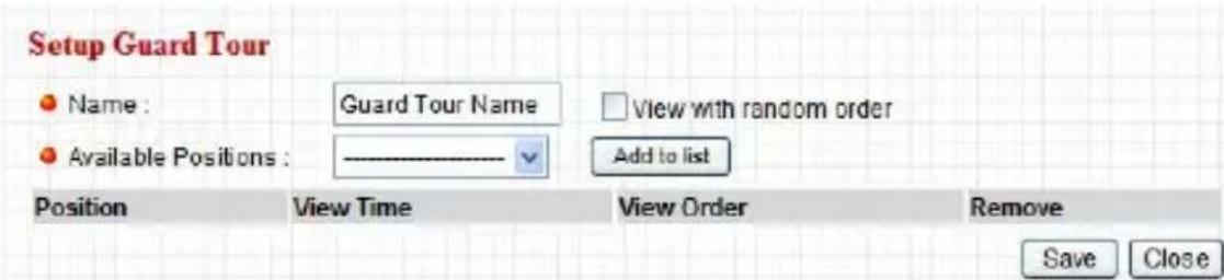
text_image
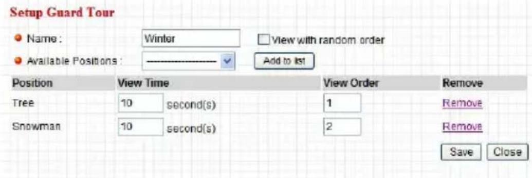
Name: Winter View with random order Available Positions: Add to list Position View Time View Order Remove Tree 10 second(s) 1 Remove Snowman 10 second(s) 2 Remove Save CloseSetup Guard Tour
Name
The name of Guard Tour Name.
Available Positions
You can choose a preset position for Guard Tour.
View with random If you enable this option, the Guard Tour will be order into random mode.
Add to List
After choose Preset Position, you can press "Add to list" button to add position into Guard Tour list.
Position The Preset Position of Guard Tour
View Time The duration of display image. The value: 1\~9999 seconds.
View Order Guard Tour display order number. The value: 1\~99 and must be unique.
Remove You can press "Remove" button to remove preset position
Save After finish Guard Tour settings, remember pressing "Save" to store all parameters.
Close After finish settings, you can press "Close" button to close setting window.
How to create a new Guard Tour?
STEP 1: Create Preset Position
- Select position and enter Name into "Position Name" field (Ex:
Window, Door...)
- Press "Add" Button to save the preset position.

text_image
Preset Positions Position Name: Available Positions: Add Goto RemoveSTEP 2: Create a new Guard Tour
- Press "Add" button
text_image
Guard Tour Name Running Mode Guard Tour List : Add Edit Start / Stop RemoveSTEP 3: Setup Guard Tour
text_image
Setup Guard Tour Name: Guard Tour Name View with random order Available Positions: Add to list Position View Time View Order Remove Save Close- Enter Guard Tour name into "Name" filed
- Select Available Positions then press "Add to list" button
Available Positions : Add to list
3. Modify the Guard Tour list
text_image
Setup Guard Tour Name: Winter View with random order Available Positions: Add to list Position View Time View Order Remove Tree 10 second(s) 1 Remove Snowman 10 second(s) 2 Remove Save Close- You can modify the View Time and View Order or remove which position
- After modified all items then press "Save" button to save all parameters.
- Press "Close" button to finish Setup Guard Tour"
STEP4: Start Guard Tour
- Select on Guard Tour list then press "Start/Stop" to active Guard Tour

text_image
Guard Tour Name Running Mode Winter=no sequential • Guard Tour List: Add Edit Start / Stop Remove- Click on Camera Item and view the Guard Tour process

text_image
Internet Camera Camera PTZ LAN WLANPosition1

natural_image
Decorative snowman figurine wearing a green hat and scarf, standing beside a Christmas tree (no text or symbols visible)Position2
After 10 seconds

natural_image
Decorative snowman figurine with snowflake and scarf, next to a small Christmas tree (no text or symbols)Cruise Tour Path
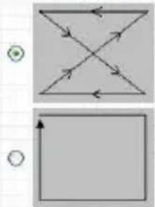
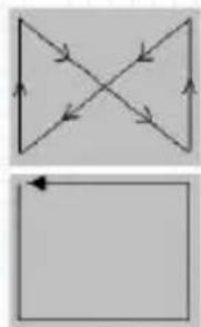
natural_image
Two abstract geometric diagrams with arrows and circles, no text or symbols present◇
flowchart
graph TD
    A["Top Left"] --> B["Top Right"]
    B --> C["Bottom Right"]
    C --> D["Bottom Left"]
    style A fill:#f9f,stroke:#333
    style B fill:#ccf,stroke:#333
    style C fill:#cfc,stroke:#333
    style D fill:#fcc,stroke:#333
Cruise Tour
Cruise Tour Path
There are four paths of Cruise Tour. That means device can follow different tour path for cruising.
Apply
After select the Cruise Tour Path, please press "Apply" button to finish.
LAN Setting

text_image
Internet Camera LAN • Network Type: ○ DHCP ○ Static IP Address • IP Address: 10.0.11.250 • Subnet Mask: 255.255.255.0 • Gateway: 10.0.11.1 • Primary DNS: 168.95.1.1 • Secondary DNS: • Video Port: 4321 • HTTP Port: 80 PPPoE • Enable PPPoE: ○ Enable ○ Disable • User Name: • Password: • MTU: 1392 (512<=MTU Value<=1492) Dynamic DNS • Enable DONS: ○ Enable ○ Disable • Provider: dynamic.org • Host Name: dinfo-host • User Name: dinfo-account • Password: ********** UPnP • Enable UPnP: ○ Enable ○ DisableLAN
Network Type
This camera can obtain IP via DHCP protocol or specified static IP Address to it..
IP Address
Enter an unused IP Address within the IP address range used on your LAN. If the IP Address of your LAN is from the 192.168.2.0 to 192.168.2.250, you can set an unused IP Address from the range for the
camera, for example: 192.168.2.250.
Subnet Mask
The Subnet Mask field must match the subnet setting on your LAN. For example: 255.255.255.0.
Gateway
The Gateway is used to forward frames to destinations in a different subnet on the Internet. The Gateway setting must be the same with the gateway used by the PCs on your LAN.
NOTE: make sure that IP address assigned to the camera will have access to the internet via the internet gate of your LAN, otherwise servers\ protocols for outside LAN connecting might be inaccessible
DNS Server
DNS Server (Domain Name Server) that translates names to IP addresses. Set the same DNS Server as the PCs on your LAN.
Video Port
The AV Control Port is used to transmit or receive the AV streaming in the network. The default port setting is "4321". If you want to view the video from
the camera, the port setting should be correct.
Web Port
This camera support web connection, the default web port is 80. Since the web server may use port 80, you can use a different port for the camera. If you change the web port from 80 to 8080, you must type http://192.168.2.3:8080 to connect the camera through the web browser.
Apply
When you finish the "LAN", click "Apply".
PPPoE
| Enable PPPoE | Enable or disable PPPoE function of the camera. |
| User Name | Enter the User Name for the PPPoE Connection. |
| Password | Enter the Password for the PPPoE Connection. |
| MTU | |
| Apply | When you finish the “PPPoE” setting, click “Apply”. |
Dynamic DNS
| Enable DDNS | Enable or disable DDNS function of the camera. |
| Provider | Several companies provide DDNS service. This camera supports the service from DynDNS company. |
| Domain Name | The domain name given by DynDNS is “registername.dyndns.com”. Enter the domain name that you register for the camera from DynDNS web site. |
| User Name | Enter the login name for the DDNS service. |
| Password | Enter the password for the DDNS service. |
| Apply | When you finish the “Dynamic DNS” setting, click “Apply”. |
UPnP
Enable UPNP
Enable or disable UPnP function of the camera.
Apply
When you finish the "UPnP" setting, click "Apply".
LoginFree
- Filename :
Apply
loginfree
.jpg
LoginFree
Filename
The default value is "loginfree". That's mean user can get a snapshot image from Internet Explorer. The format is like:
IP Camera will send a snapshot image to Internet Explorer. If user changed file name (Ex: “1234”), the URL must be changed to “http://192.168.2.3/1234.jpg”
Apply
When you finish the "UPnP" setting, click "Apply".
WLAN(\* Wireless Model Only)
Internet Camera
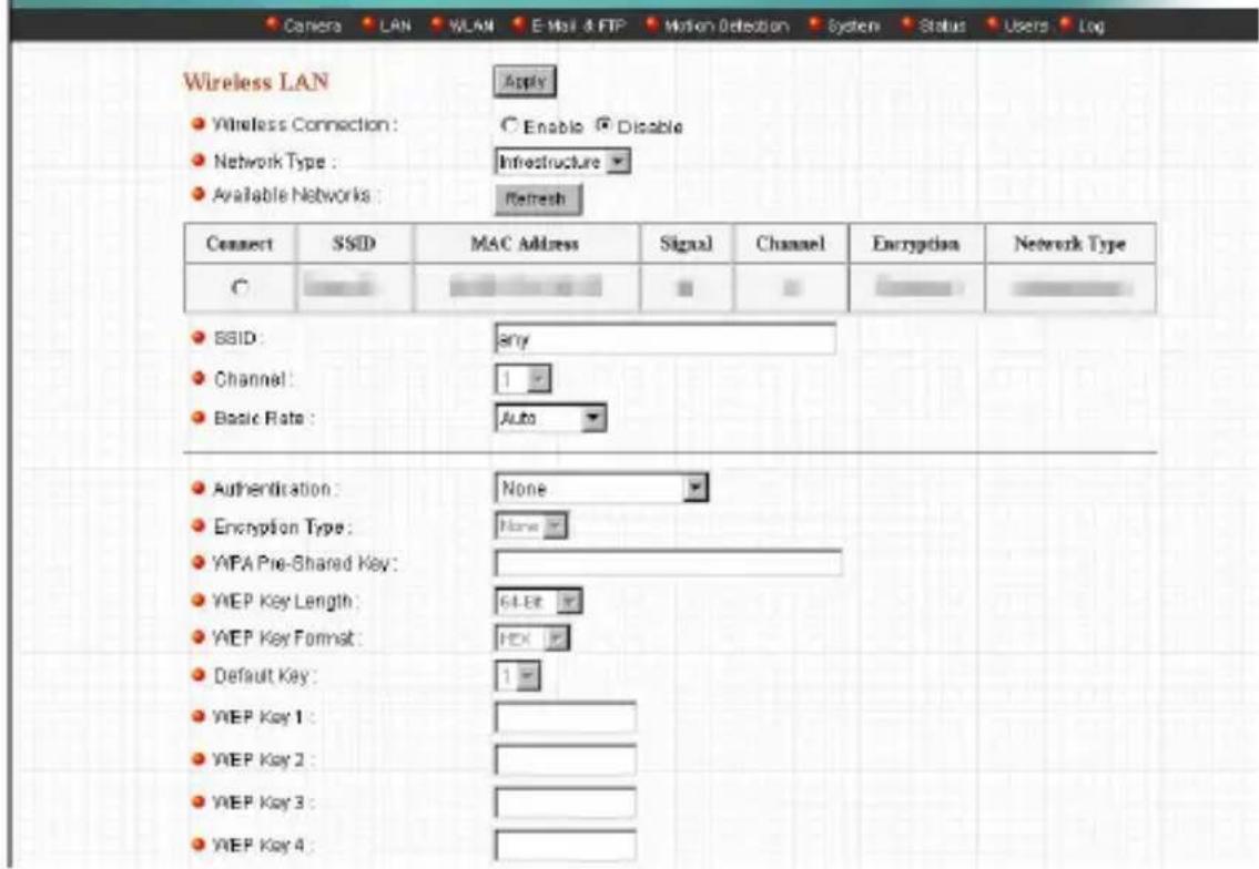
text_image
Camera LAN WLAN E-mail & FTP Motion Detecion System Status Users Log Wireless LAN ● Wireless Connection: ○ Enable ● Disable ● Network Type: Infrastructure ● Available Networks: Refresh Connect SSID MAC Address Signal Channel Encryption Network Type ○ ● SSID: any ● Channel: 1 ● Basic Rate: Auto ● Authentication: None ● Encryption Type: None ● WPA Pre-Shared Key: ● WEP Key Length: 64.8E ● WEP Key Format: FEX ● Default Key: 1 ● WEP Key 1: ● WEP Key 2: ● WEP Key 3: ● WEP Key 4:Wireless Setting
Wireless connection Enable or disable the wireless function of the Internet Camera. By default, the function is disabled.
Network Type
Infrastructure – This operation mode requires the presence of a Wireless LAN Access Point or Router. All communication is done via the Access Point or Router.
Ad-Hoc – Select this mode if you want to connect to another wireless stations in the Wireless LAN network without through an Access Point or Router.
Available Networks
Select the networks listed below and click apply to connect to the specified network.
SSID
The SSID (up to 32 printable ASCII characters) is the unique name identified in a WLAN. The ID prevents the unintentional merging of two co-located WLANs.
You may specify a SSID for the card and then only the device with the same SSID can interconnect to the card. If you want to add one of the networks nearby to the profile list, pull down the menu, all the networks nearby will be listed and you can add one of them to the profile list.
Channel
This setting is only available for Ad Hoc mode.
Select the number of the radio channel used for the networking. The channel setting should be the same with the network you are connecting to.
Basic Rate
The camera will force to the data rate that you selected to transmit data.
Authentication and Choose the authentication type you want to use.
Encryption Type
“None” means that you don’t want any encryption for wireless. “Open System” means that you can use WEP for encryption or not to encryption. When you select “Shared Key”, you must use WEP for encryption. The last option is “WPA-PSK”. When you select this authentication type, you can encryption your wireless with WPA-TKIP or WPA-AES.
WPA Pre-Shared Key
The WPA-PSK key can be from 8 to 64 characters and can be letters or numbers. This same key must be used on all of the wireless stations in the network.
WEP Key Length
You may select 64-bit or 128-bit to encrypt
transmitted data. Larger key length will provide higher level of security, but the throughput will be lower.
WEP Key Format
Hexdecimal – Only “A-F”, “a-f” and “0-9” are allowed to be set as WEP key.
ASCII – Numerical values, characters or signs are allowed to be WEP key. It is more recognizable for user.
Default Key
Select one of the keys (1\~4) as the encryption key.
Key1 \~ Key4
The WEP keys are used to encrypt data transmitted in the wireless network.
Fill the text box by following rules below.
64-bit – Input 10-digit Hex values (in the “A-F”, “a-f” and “0-9” range) or 5-digit ASCII characters (including “a-z” and “0-9”) as the encryption keys.
For example: "0123456aef" or "test1".
128-bit – Input 26-digit Hex values (in the “A-F”, “a-f” and “0-9” range) or 13-digit ASCII characters
(including "a-z" and "0-9") as the encryption keys. For example: "01234567890123456789abcdef" or "administrator".
Apply
When you finish "WLAN" setting, click this button to validate the setting values.
E-Mail and FTP
The “E-Mail & FTP” lets you setup E-Mail client and FTP client that camera can sent live video to your e-mail account or FTP server when Motion has been detected.

text_image
Internet Camera Camera LAN WLAN E-Mail & FTP Motion Detection System Status Users Log E-Mail Apply Send a Text Email Recipient E-Mail Address : SMTP Server : Sender E-Mail Address : SMTP Authentication : Enable Disable UserName : Password : FTP Configuration Apply Upload a text file FTP Server : FTP Port : 21 User Name : Password : Remote Folder : Passive Mode : Enable DisableE-Mail & FTP Settings
Recipient E-Mail Address This camera supports “Motion Detection” function. Enter the E-Mail Account for receiving the pictures.
SMTP Server Enter the SMTP Server for the E-Mail sending.
Sender E-Mail Address Specified the e-mail address of the e-mail sender.
SMTP Authentication Enable or Disable the SMTP Authentication function
Username When Authentication is enabled, input the SMTP Username.
Password When Authentication is enabled, input the password.
Send a Test Email Press this button to send a test e-mail to your mailbox. You can use this function to test if your setting is correct.
| FTP Server | This camera supports “Motion Detection” functions. When Motion Detection event occurred, you can record the pictures to FTP server. Enter the FTP address for receiving the pictures. |
| FTP Port | Enter the port of the FTP server. |
| User Name | Specify the user account of ftp server. |
| Password | Specify the Password of your ftp account. |
| Remote Folder | Specify the folder of the ftp site that you want to store the video. |
| Password | When Authentication is enabled, input the password. |
| Passive Mode | If your Camera is under NAT, you usually need to enable this feature. |
Motion Detection
The “Motion Detection” allows users to setup the behavior of motion detection feature.
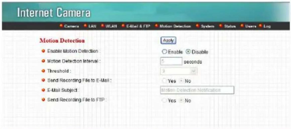
text_image
Internet Camera Camera LAN WLAN E-Mail & FTP Motion Detection System Status Users Log Motion Detection Enable Motion Detection : Motion Detection Interval : Threshold : Send Recording File to E-Mail : E-Mail Subject : Send Recording File to FTP : Apply Enable Disable 5 seconds 3 Yes No Motion Detection Notification Yes NoMotion Detection
Motion Detection Enable or Disable the Motion Detection Function. Enable
Next Event Detected Setup the interval between two events. For Interval example, if you setup the interval to 5 seconds, the next event will start after this event finished + 5 seconds.
Threshold Setup the sensitivity of motion detection.
Send Recording File to Select Yes to send the recorded video file to your
IP camera
E-Mail e-mail account that you had specified at “E-Mail & FTP” menu.
E-Mail Subject Specify the subject of motion detection notify e-mail.
Send Recording File to Select Yes to send the recorded video file to your FTP FTP server that you had specified at “E-Mail & FTP” menu.
System
The “System” allows users to setup the camera’s parameters, like camera name, data/time setting. And also provide firmware upgrade and reset tools at this page.

text_image
Internet Camera Camera Information Apply Camera Name : admin Login Name : Password : Confirm Password : Date / Time Setting Apply Set Date/Time manually 2005 / 11 / 11 16 : 59 : 41 NTP Server Time Zone : (GMT+06.00) Taipei NTP Server : 192.43.214.19 Utilities Upgrade Firmware : Browse... Reset To Factory Defaults : Reset Reboot Device : Reboot LED Setting : LED Light OFFSystem
Camera Name
The default camera name is "IC1500". It is recommended to name a meaningful name for the camera.
Login Name Setup your administrator account's login name. Default name is "admin"
Password Enter up to 4 digits password for the new user account.
Confirm Password Enter the password again to confirm the setting.
Set Date/Time Display the current Date and Time. manually
NTP Server Synchronize the Date and Time with this NTP server.
Time Zone Select the time zone that your camera put on.
NTP Server Specify the IP Address of the NTP Server.
Upgrade Firmware You can upgrade camera's firmware via this function. Press the browse button, find the correct firmware and press upgrade.
Reset to Factory If you want to reset all the camera settings to Defaults default, click this button.
Reboot Device To reboot the Internet Camera, click "Reboot".
LED Setting There are four LEDs to indicate the status of Internet Camera. If you want to secure the camera from noticing, you can turn off the LED light by clicking “LED Light OFF”. To turn on the LED light, click “LED Light ON”.
Status
The “Status” shows the current firmware version, uptime, system time and IP information of this camera.
Internet Camera
Camera LAN WLAN E-Mail & FTP Motion Detection System Status Users Log
Status
Firmware Version: IC-1500Wg v1.14 (Aug 2 2006 10:18:45)
Device Uptime: 3 min 14 sec
System Time: 2008/08/03 07:53:17
LAN
IP Address: 10.0.11.129
Subnet Mask: 255.255.255.0
- Gateway: 10.0.11.1
DNS Server: 192.168.1.2; 168.95.1.1
MAC Address: 00.00:10:11:12:00
Video Port: 4321
HTTP Port: 80
PPPoE
Link Status: Distconnected
IP Address:
Subnet Mask
Gateway
DNS Server
Users
The “Users” allows users to add four user accounts which are able to view video from Camera Viewer and Web Management. These users, unlike Administrator, are not allowed to configure the camera.

text_image
Internet Camera Users User 1: C Enable ☑ Disable Login: Password: Confirm password : Apply User 2: C Enable ☑ Disable Login: Password: Confirm password : Apply User 3: C Enable ☑ Disable Login: Password: Confirm password : Apply User 4: C Enable ☑ Disable Login: Password: Confirm password : ApplyUser 1 / 2 / 3 / 4
User #
Enable or Disable the user number #.
Login
Enter the the login name to the camera.
Password
Enter up to 4 digits password for the new user account.
Confirm Password
Enter the password again to confirm the setting.
Apply
Click "Apply" to save the user account setting.
Log
The “Log” allows users to monitor the device event and time. If you have trouble to use this device, the log file will help administrator to know the status of device.
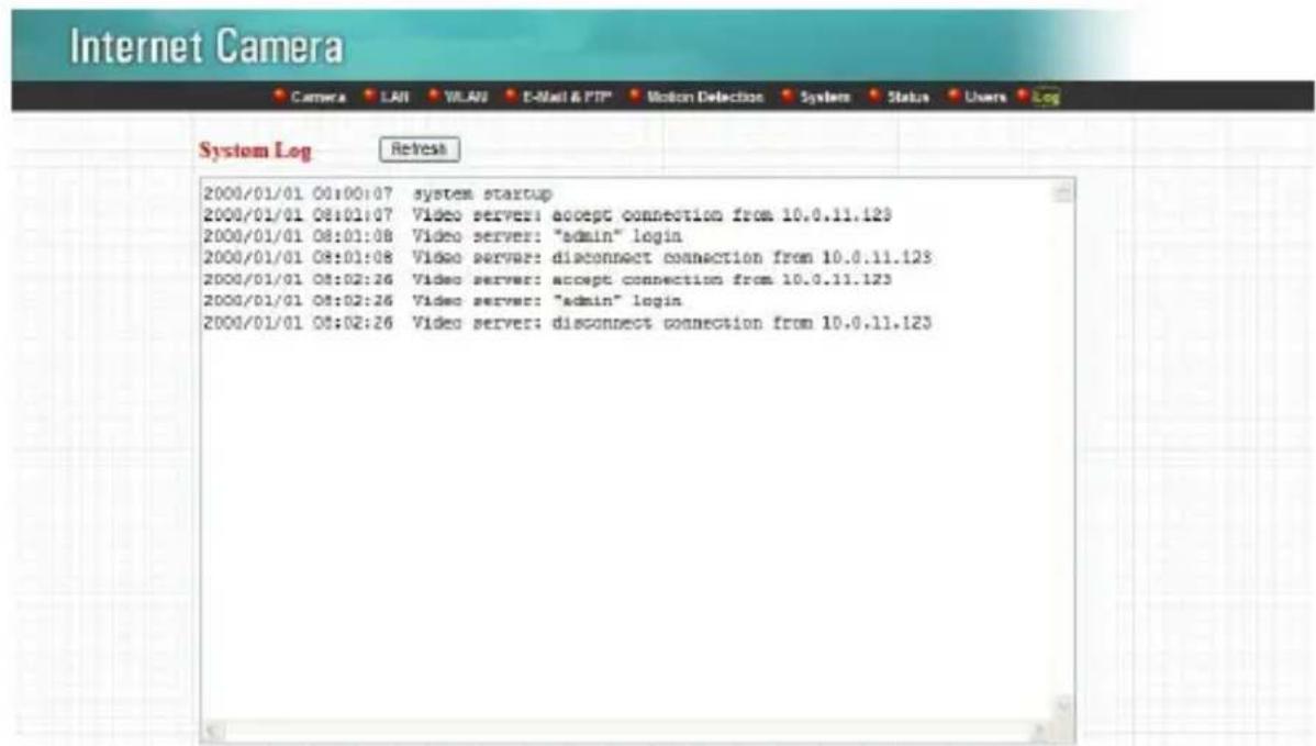
text_image
Internet Camera Camera LAI WLAU E-Mail & FTP Motion Detection System Status Users Log System Log Refresh 2000/01/01 00:00:07 system startup 2000/01/01 08:01:07 Video servers: accept connection from 10.0.11.123 2000/01/01 08:01:08 Video server: "admin" login 2000/01/01 08:01:08 Video server: disconnect connection from 10.0.11.123 2000/01/01 08:02:26 Video server: accept connection from 10.0.11.123 2000/01/01 08:02:26 Video server: "admin" login 2000/01/01 08:02:26 Video server: disconnect connection from 10.0.11.123Log
Log screen
The screen will show event and event time of device.
Refresh
You can press "Refresh" button to refresh the log screen.
Frequently Asked Questions
Q1: What is an Internet Camera?
A: The Internet Camera is a standalone system connecting directly to an Ethernet or Fast Ethernet network. It is different from the conventional PC Camera; the Internet Camera is an all-in-one system with built-in CPU and web-based solutions providing a low cost solution that can transmit high quality video images for monitoring. The Internet Camera can be managed remotely, accessed and controlled from any PC/Notebook over the Intranet via a web browser or camera viewer.
Q2: What algorithm is used to compress the digital image?
A: The Internet Camera utilizes MJPEG video compression technology to provide high quality images. MJPEG is a standard for video compression and can be applied to various application software.
Q3: Can I capture or record still images from the Internet Camera?
A: Yes, you are able to capture or record still images with the snapshot function from the Camera Viewer application supplied with the Internet Camera CD-ROM.
Q4: What network cabling is required for the Internet Camera?
A: The Internet Camera uses Category 5 UTP Twisted-pair cable allowing 10 Base-T and 100 Base-T networking.
Q5: Can the Internet Camera be setup as a PC-cam on the computer?
A: No, the Internet Camera is used only on Ethernet and Fast Ethernet network.
Q6: Can the Internet Camera be connected on the network if it consists of only private IP Addresses?
A: Yes, the Internet Camera can be connected to a LAN with private IP Addresses.
Q7: The focus on the Internet Camera is bad, how can I correct it?
A: Adjust the Internet Camera focus manually.
Appendix A Router/ Gateway Setup for Internet Viewing
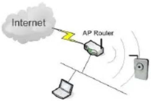
To view Internet Camera across the Internet, you have to make sure Router/Gateway has configured to pass incoming TCP/UDP connections from remote PC to the Internet Camera. The Router/Gateway should set port forwarding or virtual server for the connections. Please see the illustration as below.
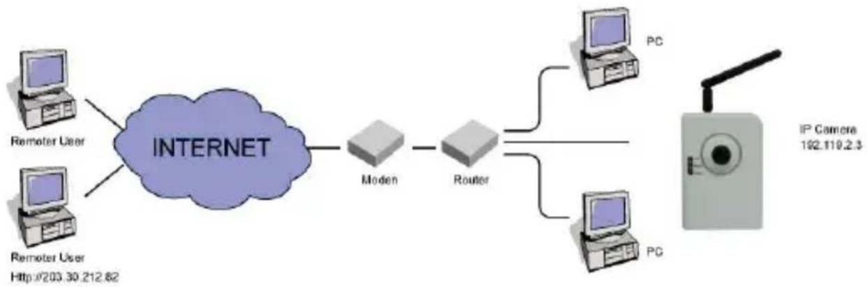
flowchart
graph LR
    A["INTERNET"] --> B["Modem"]
    B --> C["Router"]
    C --> D["PC"]
    C --> E["PG"]
    F["Remoter User"] --> A
    G["Remoter User"] --> A
    H["IP Camera 192.110.2.3"] --> I["Wireless Device"]
Router/Gateway Port Forwarding/Virtual Server Setup
| Name | Protocol | Port | LAN IP |
| Setup 1 | TCP | 80 | 192.168.2.3 |
| Setup 2 | TCP | 4321 | 192.168.2.3 |
Port Definition
Setup 1
It is the port of Web port. You have to configure the
protocol to "TCP".
Setup 2
It is the port of Video port. You have to configure the protocol to "TCP".
Setup 3
It is the port for Internet Camera and Administrator Utility communication. The protocol setting should be "UDP".
Viewing Internet Camera via Web Browser
Setup 1/Setup 2
If you want to view the video via Web Browser, you have to ensure the Router/Gateway has configured setup1 and setup 2. If the web port is not default port "80", but changed to 8080. The remote user has to enter http://203.30.212.82:8080.
Viewing Internet Camera via Camera Viewer Utility
Setup 2
If you want to use Camera Viewer Utility to view the camera, please make sure the Router/Gateway has configured setup2.
Setup Internet Camera via Administrator Utility
Setup 3
If you want to use Administrator Utility to configure
the Internet Camera via Internet, the
Router/Gateway should configure setup 3.
Appendix B Set up WLAN step by step
Please follow the procedures below:
(1) Please Check you Router Wireless settings, Suggesting Open System (Disable security) first.
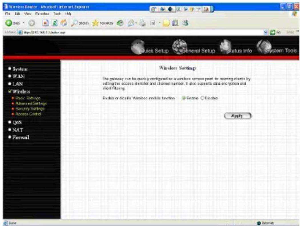
text_image
Wireless Router - Microsoft Internet Explorer File Edit View Favorites Tools Help SNO. Search Favorites Browse: http://10.168.3.2/index.asp Quick Setup General Setup Status Info System Tools Wireless Settings The gateway can be quickly configured as a wireless access point for accessing clients by setting the access identifier and channel number. It also supports data encryption and slice filtering. Enable or disable Wireless module functions Enable Disable Apply System WAN LAN Wireless Back Settings Advanced Settings Security Settings Access Controls QoS NAT Firewall
text_image
Wireless Router - Microsoft Internet Explorer File Edit View Favorites Tools Help Add Search Favorites Access http://198.200.2.2/index.asp Quick Setup General Setup Status Info System Tools Wireless Setting This page allows you to define ESSD, and Channel for the wireless command. These parameters are used for the wireless stations to connect to the Access Point. Mode: AP Band: 2.4 GHz (5×5) ESSD: Channel Number: 11 Associated Clients Show Active Clients Apply Cancel Date Internet
text_image
Wireless Router - Microsoft Internet Explorer File Edit View Favorites Tools Help SAC Browse Favorites Address Map (192.168.3.2) order app Quick Setup General Setup Status Info System Tools Advanced Settings These settings are only for more technically advanced users who have a sufficient knowledge about wireless LAN. These settings should not be changed unless you know what affect the changes will here on your Broadband router. Authentication Type: Open System Open Key Auto Fragment Threshold: 2946 (265-2946) RTS Threshold: 2947 (0.3347) Exxon Interval: 100 (20.1021 mc) Data Rate: Auto Preamble Type: Long Preamble Short Preamble Broadcast E333D: Enabled Disabled UPP: Enabled Disabled 802.11g Protection: Enabled Disabled Apply Cancel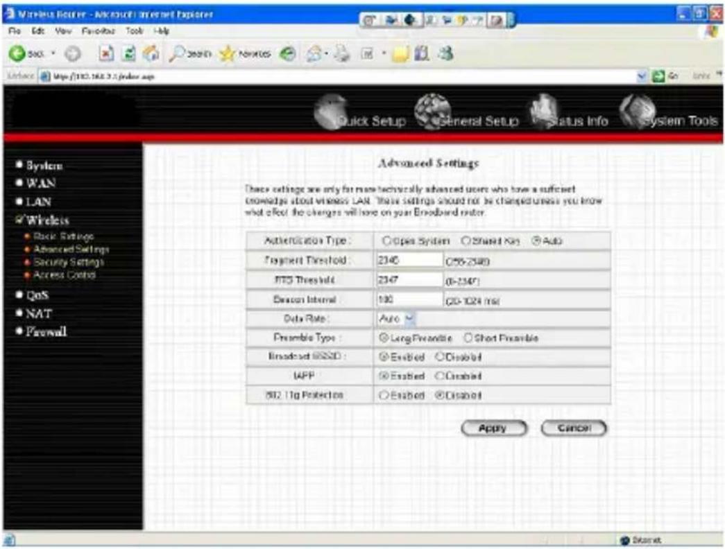
text_image
Advanced Settings These settings are only for more technically advanced users who have a sufficient knowledge about wireless LAN. These settings should not be changed unless you know what affect the changes will have on your Broadband router. Authentication Type: ○Open System ○Shared Key ●Auto Fragment Threshold: 2340 ○(55-2340) ITO Threshold: 2347 ○(5-2347) Exxon Internal: 100 ○(0-1024 ms) Data Rate: Auto Preamble Type: ○Long Renewable ○Short Preamble Broadcast @SDD: ○Enabled ○Disabled IAPP: ○Enabled ○Disabled MIL 11g Protection: ○Enabled ○Disabled Apply Cancel
text_image
Wireless Router - Microsoft Internet Explorer File Edit View Favorites Tools Help Back Search Favorites Access https://143.168.0.2/solaris.asp Quick Setup General Setup Status Info System Tools MAC Address Filtering For security reason, the Access Point features NAC Address Filtering that only allows authorized MAC Addresser associating to the Access Point MAC Address Filtering Table It allows to entry 20 sets address only. NO. MAC Address Comment Select Remove Selected Delete All Reset Enable Wireless Access Control New MAC Address CMNATC Add Cancel Apply Cancel(2) Please turn on DHCP Server of the Router for this testing.

text_image
LAN Settings You can enable the Broadband router's DHCP console dynamically allocate IP Addresses to your LAN client PCs. The broadband router must have an IP Address by the Local Area Network. LAN IP IP Address: 192.198.2.1 IP Submit Mask: 256.256.256.0 812.16 Spaning Tips: Disabled DHCP Server: Enabled Leave Time: Forward DHCP Server Star IP: 192.198.2.100 End IP: 192.198.2.200 Domain Name: Static DHCP License Table It allows to entry 16 sets address only. NO. MAC Address IP Address Select Back Back Search Search Favorites Help Quick Setup General Setup Status Info System Tools System WAN LAN Wireless QoS NAT Firewall(3) Please reset the Wireless IP Camera settings to Factory Defaults by press the Reset button over 8 seconds.
(4) Please change your PC's IP address to 192.168.2.xx (which xx from 10 to 253), Netmask = 255.255.255.0
(5) Please go to Web-Config WLAN section of the Wireless IP Camera. Press Refresh button until you find the SSID you want in the list first! Then select the Connect column of the SSID you want and select the Enable button of Wireless Connection.
Press Apply button.
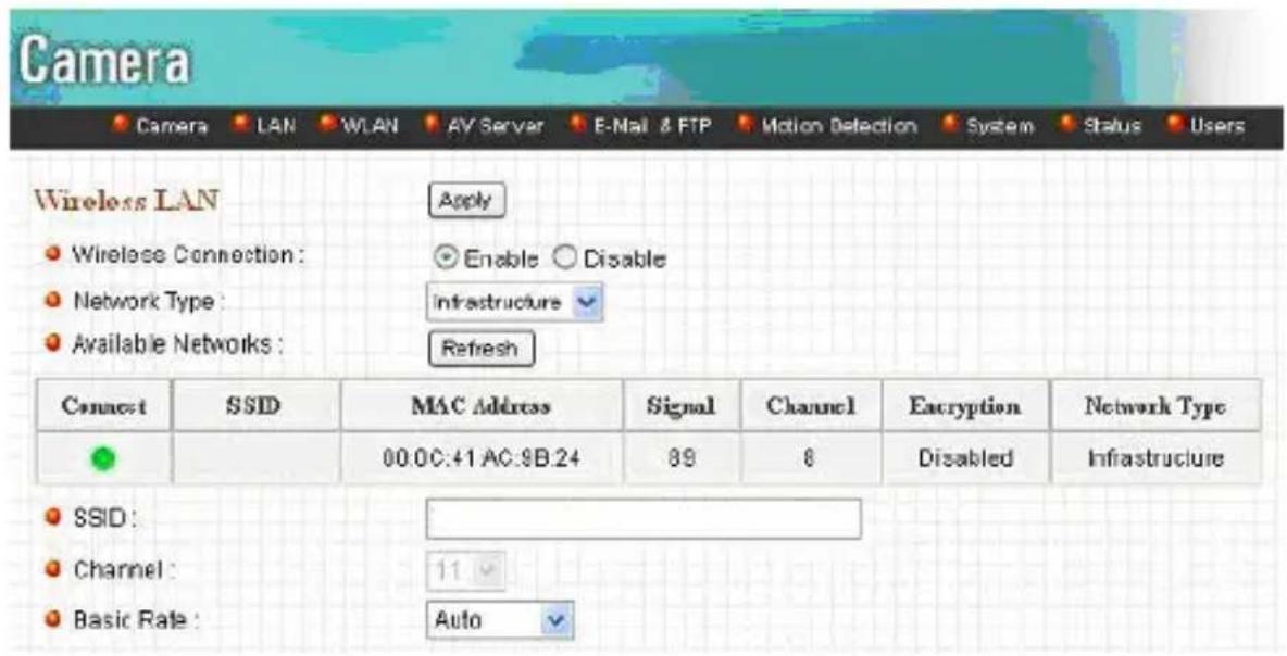
text_image
Camera Camera LAN WLAN AV Server E-Mail & FTP Motion Detection System Status Users Wireless LAN ● Wireless Connection: Apply ● Network Type: Enable ○ Disable ● Available Networks: Infrastructure ✓ Refresh Connect SSID MAC Address Signal Channel Encryption Network Type ● 00.0C:41 AC:8B:24 89 8 Disabled Infrastructure ● SSID: ● Channel: 11 ● Basic Rate: Auto ✓(6) Please go to the LAN section of Web-Config.
Select DHCP and press Apply button.
Then you could close this IE browser window now.
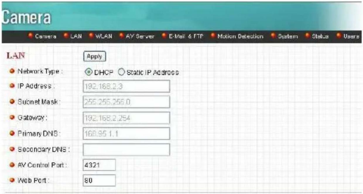
text_image
Camera Camera LAN WLAN AV Server E-Mail & FTP Motion Detection System Status Users LAN Apply Network Type: DHCP Static IP Address IP Address: 192.168.2.3 Subnet Mask: 255.255.256.0 Gateway: 192.168.2.254 Primary DNS: 168.95 1.1 Secondary DNS: AV Control Port: 4321 Web Port: 80(7) Please UNPLUG the Ethernet Cable of the Wireless IP Camera now!
(8) Wait for seconds then the Wireless IP Camera should be linked with the Wireless Router.
(9) Now you could let your PC to be connected with the Wireless Router.
(10) In this case, if your PC's DHCP Client IP is 192.168.8.101, then the Wireless IP Camera must be
192.168.8.100, because Wireless IP Camera was got IP early then your PC.
(11) You could go to the Web-Interface of the Wireless IP Camera.
Appendix C Viewing via UPnP in Windows XP
When the UPnP function is enabled, the camera can be detected by UPnP compliant system such as Windows XP. The camera will be displayed in the Neighborhood of Windows XP, so you can directly double click the camera or right click the camera and select "Invoke" to view the video through web browser.
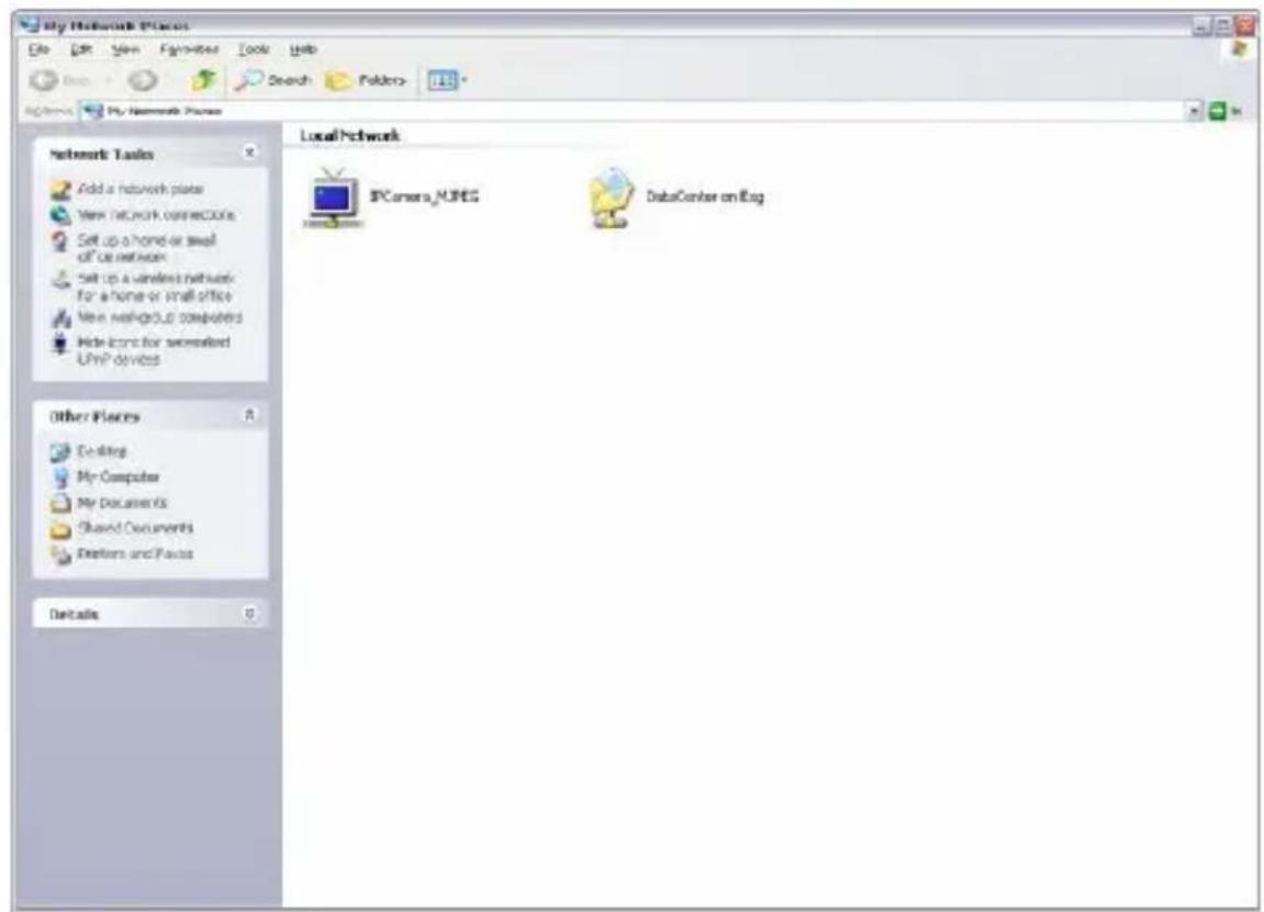
text_image
My Network Files File Edit View Favorites Tools Help Search Folders My Network Files Network Tasks Add a network plate New Network connection Set up a home or small off-up network Set up a wireless network for a home or small office New networking computers Hide icons for semerated UPnP devices LocalNetwork IFCamera_MPEG DataCenter on Log Other Spaces Ceiling My Computer My Documents Shared Documents Desktops and Focus Details
text_image
Connect to 192.168.2.3 Internet Camera User name: Password: Remember my password OK CancelEnable UPnP in Windows XP SP2
If you can't find the camera in the Neighborhood of Windows XP SP2 or you have seen the following message when you double click the camera. You have to check if UPnP function is blocked by the firewall. Please follow the steps below to enable it.

text_image
Device Offline The device you are trying to use is not currently available on your network. Check to see if the device is on the network and try again. OK- Go to "Start\Settings\Network Connections".
- Right click the "Local Area Connection" and select "Properties".
- In the “Local Area Connection Properties”, select “Advanced” option menu and click “Settings”.

text_image
Local Area Connection Properties General Authentication Advanced Windows Firewall Protect my computer and network by limiting or preventing access to this computer from the Internet! Settings... If you're not sure how to set these properties, use the Network Setup Wizard instead. OK Cancel- The "Windows Firewall" screen will be popped up, select "Exceptions" option menu.
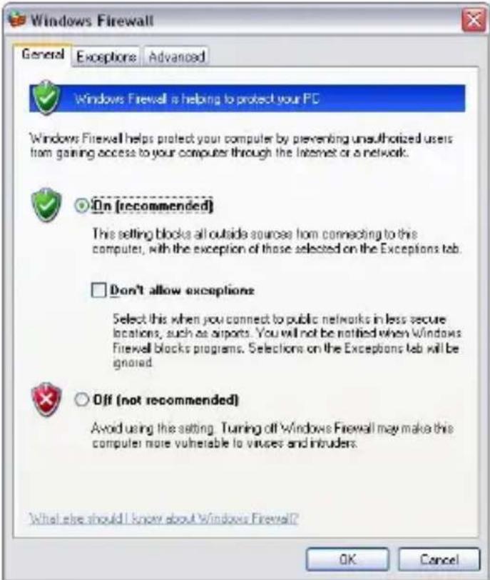
text_image
Windows Firewall General Exceptions Advanced Windows Firewall is helping to protect your PC Windows Firewall helps protect your computer by preventing unauthorized users from gaining access to your computer through the Internet or a network. On [recommended] This setting blocks all outside sources from connecting to this computer, with the exception of those selected on the Exceptions tab. Don't allow exceptions Select this when you connect to public networks in less secure locations, such as airports. You will not be notified when Windows Firewell blocks programs. Selections on the Exceptions tab will be ignored. Off (not recommended) Avoid using the setting. Turning off Windows Firewall may make this computer more vulnerable to viruses and intruders. What else should I know about Windows Firewall? OK Cancel- Enable "UPnP Framework" from the "Programs and Services list" and click "Ok".
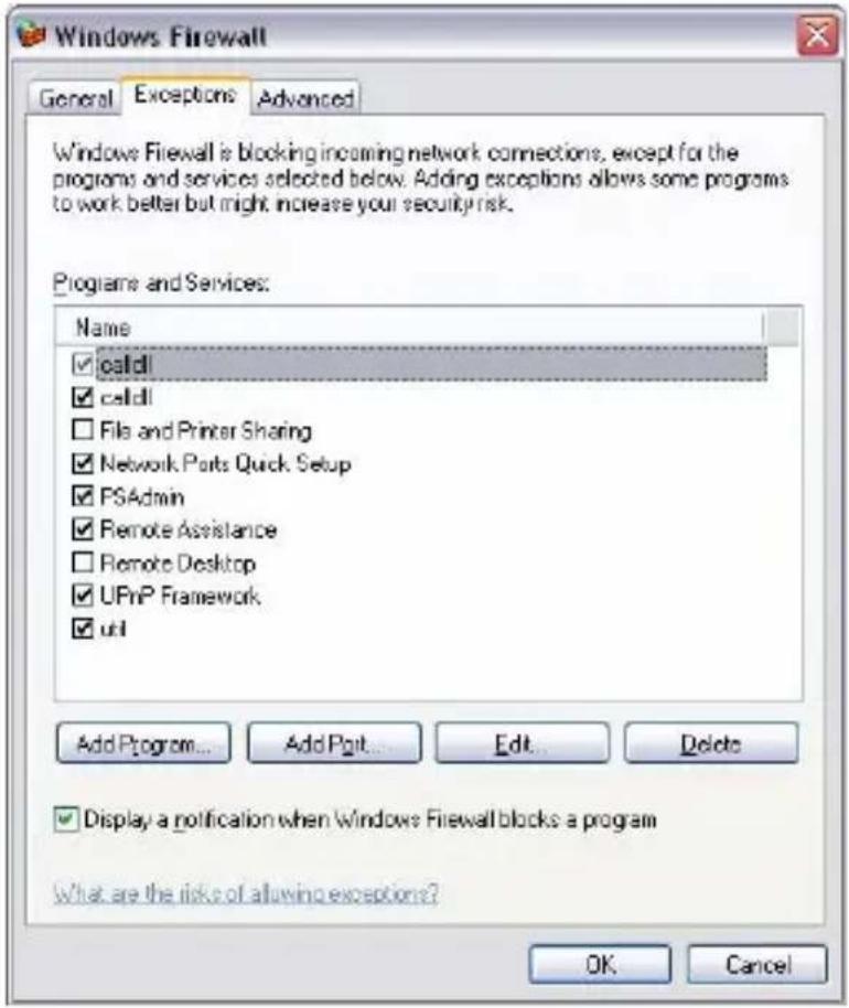
text_image
Windows Firewall General Exceptions Advanced Windows Firewall is blocking incoming network connections, except for the programs and services selected below. Adding exceptions allows some programs to work better but might increase your security risk. Programs and Services: Name ✓ calidl ✓ calidl □ File and Printer Sharing ✓ Network Ports Quick Setup ✓ PSAadmin ✓ Remote Assistance □ Remote Desktop ✓ UPnP Framework ✓ util Add Program... Add Pplt... Edit... Delete ✓ Display a notification when Windows Firewall blocks a program What are the risks of allowing exceptions? OK CancelAppendix D Configure Windows 2003 Server
Graphics Hardware Acceleration and DirectX are disabled by default on a Server configuration to ensure maximum stability and uptime. But for any reason you need to enable them to use DirectX enabled applications this section will guide you through on how you can do it.
Enabling Graphics Hardware Acceleration
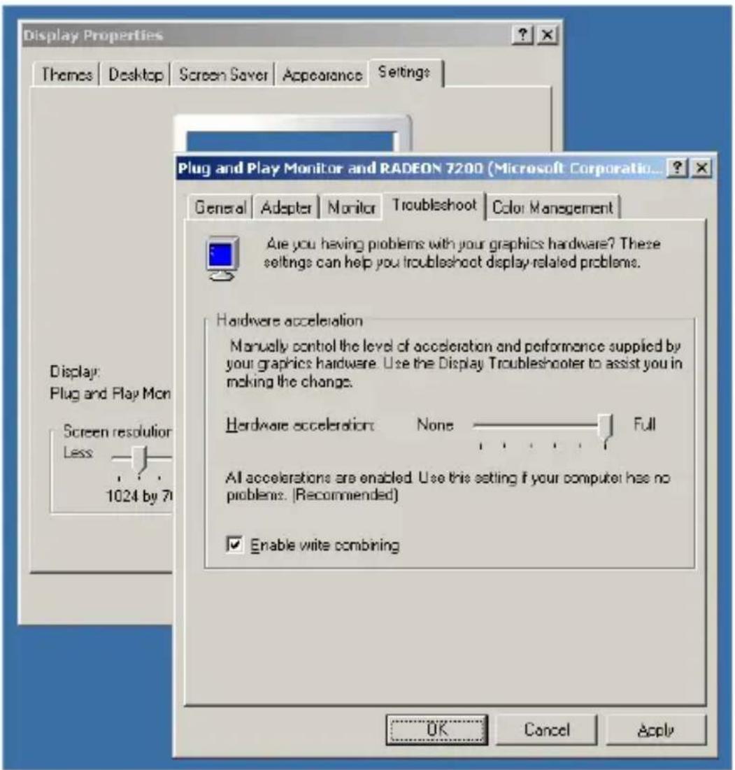
text_image
Display Properties Themes Desktop Screen Saver Appearance Settings Plug and Play Monitor and RADEON 7200 (Microsoft Corporation... General Adapter Monitor Troubleshoot Color Management Are you having problems with your graphics hardware? These settings can help you troubleshoot display-related problems. Hardware acceleration Manually control the level of acceleration and performance supplied by your graphics hardware. Use the Display Troubleshooter to assist you in making the change. Hardware acceleration None Full All accelerations are enabled. Use this setting if your computer has no problems. (Recommended) Enable write combining Display: Plug and Play Mon Screen resolution Less 1024 by 71 OK Cancel Apply- Simply right click anywhere on your desktop and select Properties -> Settings tab -> Advanced -> and finally, the Troubleshoot tab.
- Now move the Hardware acceleration slider across to Full
- Click OK
- You may experience a monitor black out for a few seconds, this is normal.
Enabling DirectX
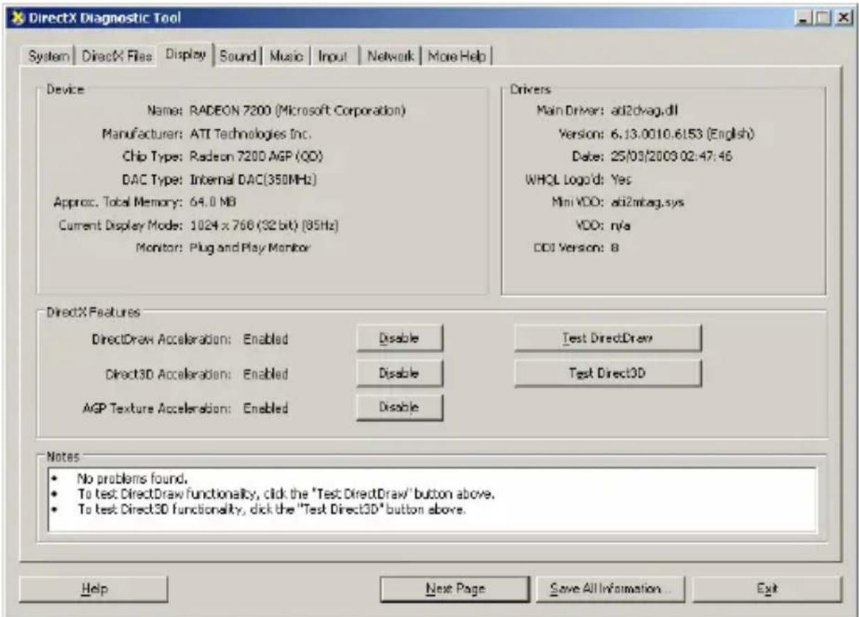
text_image
DirectX Diagnostic Tool System DirectX Files Display Sound Music.Input Network More Help Device Name: RADEON 7200 (Microsoft Corporation) Manufacturer: ATI Technologies Inc. Chip Type: Radeon 7200 AGP (QD) DAC Type: Internal DAC(350MHz) Approx. Total Memory: 64.0 MB Current Display Mode: 1024 x 766 (32 bit) (85Hz) Monitor: Plug and Play Monitor Drivers Main Driver: ab2dvag.dll Version: 6.13.0010.6153 (English) Date: 25/03/2009 02:47:46 WHQL Logo'd: Yes Mini VDD: ab2mbag.sys VDD: n/a DDI Version: 8 DirectX Features DirectDraw Acceleration: Enabled Disableoya Direct3D Acceleration: Enabled Disableoya AGP Texture Acceleration: Enabled Disableoya Test DirectDraw Test Direct3D Notes • No problems found. • To test DirectDraw functionality, click the "Test DirectDraw" button above. • To test Direct3D functionality, click the "Test Direct3D" button above. Help Next Page Save All Information... Exit- go to Start -> Run -> and type dxdiag followed by enter. You will get a dialog box asking if you want to allow dxdiag to access the
internet to check for valid WHQL certificates - click on Yes.
- Let's click on the Display tab, now click on all three boxes to enable DirectDraw, Direct3D and AGP Texture Acceleration.