TC-D5511RX - Surveillance Camera IDIS - Free user manual and instructions
Find the device manual for free TC-D5511RX IDIS in PDF.


| Product Type | Surveillance Camera |
| Brand | IDIS |
| Model | TC-D5511RX |
| Resolution | Up to 5MP (20fps) / 4MP (30fps) / 2MP (30fps) |
| Lens Type | Manual varifocal (likely DC drive) |
| Day/Night Function | Auto (IR cut filter), Color, B&W, EXT (external sensor), SMART IR |
| Wide Dynamic Range | WDR mode (Frame/Line) with ROI |
| Backlight Compensation | HLC, BLC, ACE, WDR |
| White Balance | Auto, AutoExt, AWC-SET, Manual |
| Noise Reduction | 3D DNR (Off/Low/Middle/High) |
| Motion Detection | Up to 4 detection windows, sensitivity adjustable |
| Privacy Mask | Up to 16 zones (box or polygon) |
| Digital Zoom | 1.0x to 16.0x |
| Image Adjustments | Sharpness, Gamma, Color Gain, Mirror, Flip, Defog, Shading |
| Video Output | HD-TVI, HD-CVI, CVBS (selectable), analog |
| Power Supply | 12V DC (typical, not explicitly stated) |
| Power Consumption | Approx. 5W (estimated) |
| Dimensions | Approx. 120 x 80 x 70 mm (estimated) |
| Weight | Approx. 0.5 kg (estimated) |
| Operating Temperature | -10°C to +50°C (estimated) |
| Cleaning | Unplug, use damp soft cloth; no liquid or aerosol cleaners |
| Safety | Read instructions, retain manual, avoid water, use approved mounting |
| Repair/Spare Parts | Use manufacturer approved parts; servicing by qualified personnel only |
| Certifications | FCC Class A, CE, WEEE |
| Language Support | English, Chinese, Japanese, Korean |
Frequently Asked Questions - TC-D5511RX IDIS
User questions about TC-D5511RX IDIS
0 question about this device. Answer the ones you know or ask your own.
Ask a new question about this device
Download the instructions for your Surveillance Camera in PDF format for free! Find your manual TC-D5511RX - IDIS and take your electronic device back in hand. On this page are published all the documents necessary for the use of your device. TC-D5511RX by IDIS.
USER MANUAL TC-D5511RX IDIS
Before reading this manual
This is a basic operation manual for use of an IDIS camera. Users who are using this product for the first time, as well as users with experience using comparable products, must read this operation manual carefully before use and heed to the warnings and precautions contained herein while using the product. Safety warnings and precautions contained in this operation manual are intended to promote proper use of the product and thereby prevent accidents and property damage and must be followed at all times. Once you have read this operation manual, keep it at an easily accessible location for future reference.

- The manufacturer will not be held responsible for any product damage resulting from the use of unauthorized parts and accessories or from the user's failure to comply with the instructions contained in this manual.
- The information in this document is believed to be accurate as of the date of publication even though explanation about some functions may not be incorporated. The manufacturer is not responsible for any problems resulting from the use thereof. The information contained herein is subject to change without notice. Revisions or new editions to this publication may be issued to incorporate such changes.
- It is recommended that first-time users of this camera and individuals who are not familiar with its use seek technical assistance from their retailer regarding product installation and use.
- If you need to disassemble the product for functionality expansion or repair purposes, you must contact your retailer and seek professional assistance.
- Both retailers and users should be aware that this product has been certified as being electromagnetically compatible for commercial use. If you have sold or purchased this product unintentionally, please replace with a consumer version.
Safety Symbols
| Symbol | Publication Description | |
| --- | IEC60417, No.5031 | Direct current |
In-Text
| Symbol | Type Description | |
 | Caution | Important information concerning a specific function. |
 | Note | Useful information concerning a specific function. |
Safety Precautions
WARNING
RISK OF ELECTRIC SHOCK
DO NOT OPEN
WARNING: TO REDUCE THE RISK OF ELECTRIC SHOCK,
DO NOT REMOVE COVER (OR BACK).
NO USER-SERVICEABLE PARTS INSIDE.
REFER SERVICING TO QUALIFIED SERVICE PERSONNEL.
Important Safeguards
1. Read Instructions
All the safety and operating instructions should be read before the appliance is operated.
2. Retain Instructions
The safety and operating instructions should be retained for future reference.
3. Cleaning
Unplug this equipment from the wall outlet before cleaning it. Do not use liquid aerosol cleaners. Use a damp soft cloth for cleaning.
4. Attachments
Never add any attachments and/or equipment without the approval of the manufacturer as such additions may result in the risk of fire, electric shock or other personal injury.
5. Water and/or Moisture
Do not use this equipment near water or in contact with water.
6. Placing and Accessories
Do not place this equipment on an wall or ceiling that is not strong enough to sustain the camera. The equipment may fall, causing serious injury to a child or adult, and serious damage to the equipment. Wall or shelf mounting should follow the manufacturer's instructions, and should use a mounting kit approved by the manufacturer.

This equipment and cart combination should be moved with care. Quick stops, excessive force, and uneven surfaces may cause the equipment and cart combination to overturn.
Do not place this equipment in an enclosed space. Sufficient ventilation is required to prevent an increase in ambient temperature which can cause malfunction or the risk of fire.
7. Power Sources
This equipment should be operated only from the type of power source indicated on the marking label. If you are not sure of the type of power, please consult your equipment dealer or local power company.
You may want to install a UPS (Uninterruptible Power Supply) system for safe operation in order to prevent damage caused by an unexpected power stoppage. Any questions concerning UPS, consult your UPS retailer.
This equipment should be remain readily operable.
8. Power Cord
Operator or installer must remove power and TNT connections before handling the equipment.
9. Lightning
For added protection for this equipment during a lightning storm, or when it is left unattended and unused for long periods of time, unplug it from the wall outlet and disconnect the antenna or cable system. This will prevent damage to the equipment due to lightning and power-line surges. If thunder or lightning is common where the equipment is installed, use a surge protection device.
10. Overloading
Do not overload wall outlets and extension cords as this can result in the risk of fire or electric shock.
11. Objects and Liquids
Never push objects of any kind through openings of this equipment as they may touch dangerous voltage points or short out parts that could result in a fire or electric shock. Never spill liquid of any kind on the equipment.
12. Servicing
Do not attempt to service this equipment yourself. Refer all servicing to qualified service personnel.
13. Damage requiring Service
Unplug this equipment from the wall outlet and refer servicing to qualified service personnel under the following conditions:
A. When the power-supply cord or the plug has been damaged.
B. If liquid is spilled, or objects have hit the equipment.
C. If the equipment has been exposed to rain or water.
D. If the equipment does not operate normally by following the operating instructions, adjust only those controls that are covered by the operating instructions as an improper adjustment of other controls may result in damage and will often require extensive work by a qualified technician to restore the equipment to its normal operation.
E. If the equipment has been dropped, or the cabinet damaged.
F. When the equipment exhibits a distinct change in performance — this indicates a need for service.
14. Replacement Parts
When replacement parts are required, be sure the service technician has used replacement parts specified by the manufacturer or that have the same characteristics as the original part. Unauthorized substitutions may result in fire, electric shock or other hazards.
15. Safety Check
Upon completion of any service or repairs to this equipment, ask the service technician to perform safety checks to determine that the equipment is in proper operating condition.
16. Field Installation
This installation should be made by a qualified service person and should conform to all local codes.
17.Tmra
A manufacturer's maximum recommended ambient temperature (Tmra) for the equipment must be specified so that the customer and installer may determine a suitable maximum operating environment for the equipment.
FCC Compliance Statement
THIS EQUIPMENT HAS BEEN TESTED AND FOUND TO COMPLY WITH THE LIMITS FOR A CLASS A DIGITAL DEVICE, PURSUANT TO PART 15 OF THE FCC RULES. THESE LIMITS ARE DESIGNED TO PROVIDE REASONABLE PROTECTION AGAINST HARMFUL INTERFERENCE WHEN THE EQUIPMENT IS OPERATED IN A COMMERCIAL ENVIRONMENT. THIS EQUIPMENT GENERATES, USES, AND CAN RADIATE RADIO FREQUENCY ENERGY AND IF NOT INSTALLED AND USED IN ACCORDANCE WITH THE INSTRUCTION MANUAL, MAY CAUSE HARMFUL INTERFERENCE TO RADIO COMMUNICATIONS. OPERATION OF THIS EQUIPMENT IN A RESIDENTIAL AREA IS LIKELY TO CAUSE HARMFUL INTERFERENCE, IN WHICH CASE USERS WILL BE REQUIRED TO CORRECT THE INTERFERENCE AT THEIR OWN EXPENSE.
WARNING: CHANGES OR MODIFICATIONS NOT EXPRESSLY APPROVED BY THE PARTY RESPONSIBLE FOR COMPLIANCE COULD VOID THE USER'S AUTHORITY TO OPERATE THE EQUIPMENT. THIS CLASS OF DIGITAL APPARATUS MEETS ALL REQUIREMENTS OF THE CANADIAN INTERFERENCE CAUSING EQUIPMENT REGULATIONS.
WEEE (Waste Electrical & Electronic Equipment)
Correct Disposal of This Product
(Applicable in the European Union and other European countries with separate collection systems)
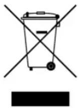
This marking shown on the product or its literature, indicates that it should not be disposed with other household wastes at the end of its working life. To prevent possible harm to the environment or human health from uncontrolled waste disposal, please separate this from other types of wastes and recycle it responsibly to promote the sustainable reuse of material resources.
Household users should contact either the retailer where they purchased this product, or their local government office, for details of where and how they can take this item for environmentally safe recycling.
Business users should contact their supplier and check the terms and conditions of the purchase contract. This product should not be mixed with other commercial wastes for disposal.
Copyright
© 2020 IDIS Co., Ltd.
IDIS Co., Ltd. reserves all rights concerning this manual.
Use or duplication of this manual in part or whole without the prior consent of IDIS Co., Ltd. is strictly prohibited.
Contents of this manual are subject to change without prior notice for reasons such as functionality enhancements.
Registered Trademarks
IDIS is a registered trademark of IDIS Co., Ltd.
Other company and product names are registered trademarks of their respective owners.
Table of Contents
1
Lens 6
Exposure Compensation....7
White Balance....7
Backlight Compensation....8
Day&Night Function....10
Dynamic Noise Reduction ....11
Image Compensation....12
Motion Detection ....14
System....15
Save & Exit ....16
Part 1 - Menu Setup
Use the OSD button equipped on the I/O device port to set up the OSD menu.
1 Press the OSD button to launch the MENU screen.
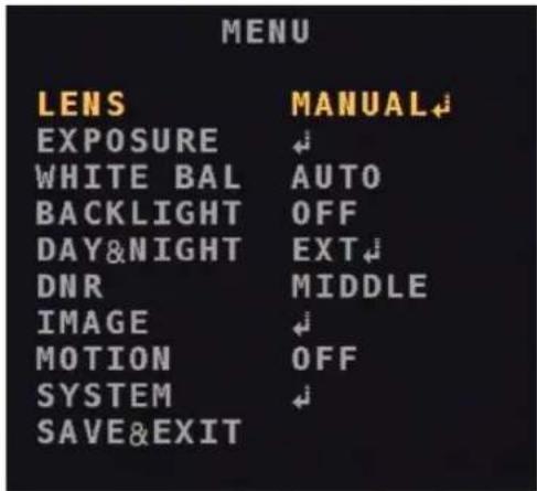
2 Use the UP or DOWN button to move an indicator. The indicator will be displayed in yellow. To select the function, press the OSD button.
3 Use the L or R button to display options of the function. Press the button until the desired value is displayed. To select the value, press the OSD button.
arrow indicates that there are submenus. Press OSD button to display submenus.
4 Move the yellow indicator to the SAVE&EXIT and press the OSD button to exit.

Dark gray functions are not available depending on the settings.
Lens
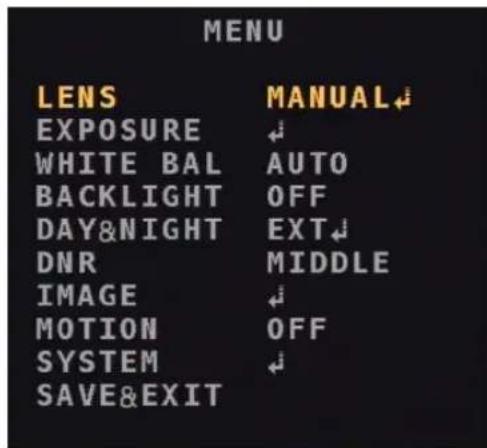
1 From the MENU screen, move the yellow indicator to the LENS using the UP or DOWN button.
2 Press the OSD button to select MANUAL.
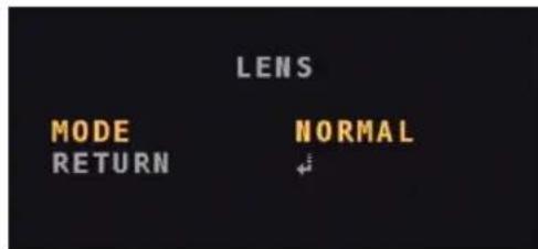
• MODE: you can select the NORMAL or DEBLUR depending on your camera installation environment.
Exposure Compensation
1 From the MENU screen, move the yellow indicator to the EXPOSURE using the UP or DOWN button.
2 Press the OSD button to load the submenus of the EXPOSURE.
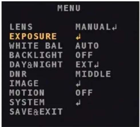
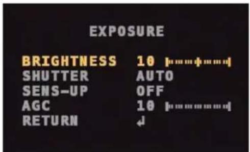
- BRIGHTNESS: Adjust the brightness on the screen. (0\~20)
- SHUTTER: Choose one of the shutter speed. (AUTO/MANUAL/FLICKER)

- The shutter speed value of the MANUAL mode is adjustable from 1/30 to 1/30,000.
- The WDR MODE in the BACK LIGHT menu does not work while the MANUAL or FLICKER is used.
- SENS-UP: Automatically detects low-light conditions and retains bright screen. (OFF\~x32)

- SENS-UP does not work while the MANUAL shutter is used.
- SENS-UP does not work while the WDR MODE in the BACK LIGHT menu is used.
- AGC: The higher the AGC value, the brighter the screen. But the image noise will also increase at the same time.
White Balance
The WHITE BALANCE function allows you to change color representation in difficult lighting conditions.
1 From the MENU screen, move the yellow indicator to the WHITE BAL using the UP or DOWN button.
2 Press the L or R button to select the desired mode and press the OSD button.
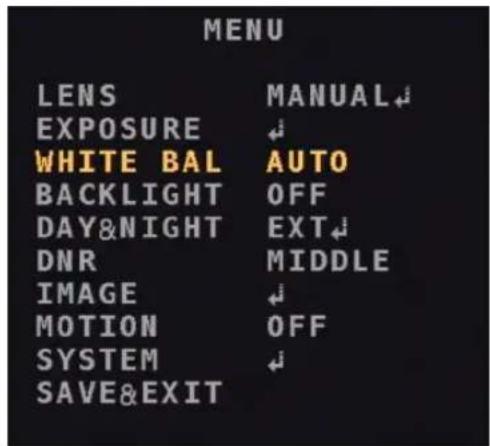
- AUTO: Automatically changes into the optimal colors depending on the surroundings.
- AUTOext: Applys suitable colors at a wider range of color temperatures than AUTO mode.
- AWC-SET: To set the best color value in the present state of lightning, hold a white object in front of the camera and press the OSD button during three seconds, then a message, PUSHING, appears and the setting will be applied. If the surroundings change, AWC-SET should be re-adjusted.
Part 1 - Menu Setup
- MANUAL: From the C-TEMP, set appropriate color temperature and then adjust the R-GAIN and the B-GAIN seeing the colors of subjects.
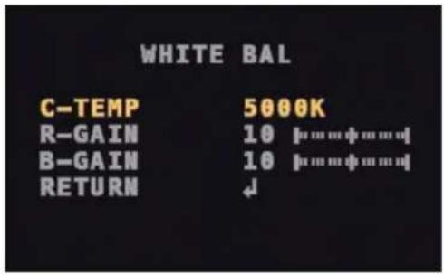
- C-TEMP: Adjust a color temperature. (3000K/5000K/8000K)
- R-GAIN: Apply red color. (0\~20)
- B-GAIN: Apply blue color. (0\~20)

Under the following conditions the WHITE BALANCE may not work properly. In this case, use the AUTOext mode.
- When the surroundings of subjects have very high color temperature. — e.g., clear sky or sunset.
- When the surroundings of subjects is very dark.
- When the camera is directly facing a fluorescent lamp or is installed in a place with a lot of light changes.
Backlight Compensation
The BACKLIGHT function allows you to choose HLC, BLC, ACE, and WDR MODE for correcting overly-bright backlit scenarios.
1 From the MENU screen, move the yellow indicator to the BACKLIGHT using the UP or DOWN button.
2 Press the L or R button to select the desired mode and press the OSD button.
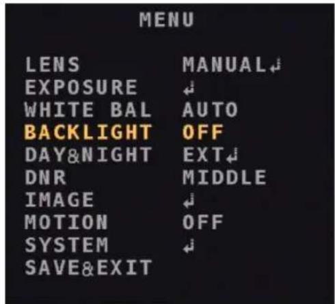
• OFF: Backlight function does not work.
- HLC: When a car headlight strongly flash at the entrance of a parking lot or a gas station at night, you can block the area of the headlight to identify the license plate.
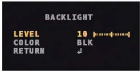
- LEVEL: Adjust the range of overexposure to light.
- COLOR: Select a color applied to the area of the overexposure. (BLK/WHT/YEL/CYN/GRN/MAG/RED/BLU)
- BLC: When a subject is against strong light, BLC allows you to see the background of the subject clearly. You can set up the applying area so that the area can be seen obvious.
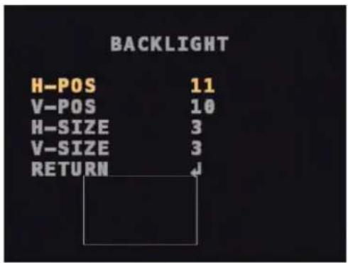
- H-POS: Adjust the horizontal position of the BLC area. (0\~26)
- V-POS: Adjust the vertical position of the BLC area. (0\~32)
- H-SIZE: Adjust the horizontal size of the BLC area. (0\~26)
- V-SIZE: Adjust the vertical size of the BLC area. (0\~32)

The maximum of the adjustable values may vary depending on the resolution.
- ACE: When there is strong backlight ACE allows you to modulate the contrast. (OFF/LOW/MIDDLE/HIGH)
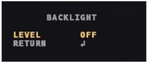

ACE does not work while the DEFOG in the IMAGE menu.
- WDR: When objects are not identified and seen dark, WDR allows you to see the screen vivid and clear.
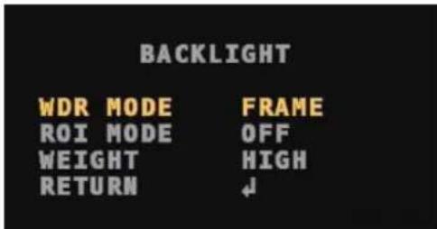
- WDR MODE: Select the mode of WDR. (FRAME/LINE)
- ROI MODE: Lower the brightness of the selected area in order to see objects clearly. The area can be adjusted in the shape of BOX or POLYGON.
BOX
Select the applying area in the shape of box.
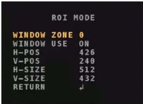
- WINDOW ZONE: Select the box. (0\~3)
- WINDOW USE: Choose the state of the box. (ON/OFF)
- H-POS: Adjust the horizontal start position. (0\~2608)
- V-POS: Adjust the vertical start position. (0\~1960)
- H-SIZE: Adjust the horizontal size of the area. (0\~2608)
- V-SIZE: Adjust the vertical size of the area. (0\~1960)

The maximum of the adjustable values may vary depending on the resolution.
POLYGON
Select the applying area in the shape of polygon. The four vertexes can be moved in order to adjust a range.
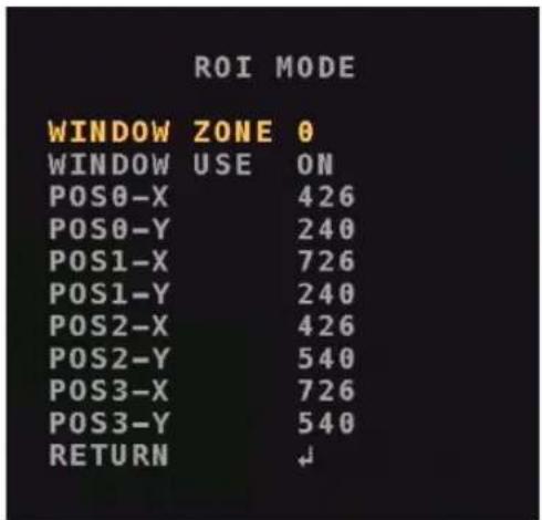
- WINDOW ZONE: Select the polygon. (0\~3)
- WINDOW USE: Choose the state of the polygon. (ON/ OFF)
-
POS0-X: Adjust the vertex of the X-coordinate at the top left. (0\~2603)
-
POS0-Y: Adjust the vertex of the Y-coordinate at the top left. (0\~1955)
- POS1-X: Adjust the vertex of the X-coordinate at the top right. (5\~2603)
- POS1-Y: Adjust the vertex of the Y-coordinate at the top right. (0\~1955)
- POS2-X: Adjust the vertex of the X-coordinate at the bottom left. (0\~2603)
- POS2-Y: Adjust the vertex of the Y-coordinate at the bottom left. (5\~1960)
- POS3-X: Adjust the vertex of the X-coordinate at the bottom right. (5\~2608)
- POS3-Y: Adjust the vertex of the Y-coordinate at the bottom right. (5\~1960)

The maximum of the adjustable values may vary depending on the resolution.
- WEIGHT: Select the weight level. Increasing the level makes the screen dark by reducing overexposure to light. (LOW/MIDDLE/HIGH)
Day&Night Function
The DAY&NIGHT function allows you to define screen in COLOR or B&W(black & white).
1 From the MENU screen, move the yellow indicator to the DAY&NIGHT using the UP or DOWN button.
2 Press the L or R button to select the desired mode and press the OSD button.
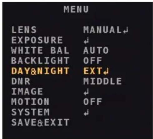
- EXT: The light sensor automatically switches the COLOR and B&W mode.
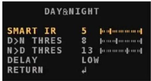
- SMART IR: Adjust the level to prevent overexposure to (infrared) light. (0\~20)
- D>N THRES: Set up the standard value during the time when day turns into night. (0\~20)
- N>D THRES: Set up the standard value during the time when night turns into day. (0\~20)
- DELAY: Set up the delay time when the screen turns into COLOR or B&W mode. (LOW/MIDDLE/HIGH)
• COLOR: Always display the screen in color.
• B&W: Always display the screen in black and white.
![DAY&NIGHT SMART IR 5 [0]IRIRIRIRIRIRIRIRIRIRIRIRIRIRIRIRIRIRIRIRIRIRIRIRIRIRIRIRIRIRIRIRIRIRIRIRIRIRIRIRIRIRIRIRIRIRIRIRIRIRIRIRIRIRIRIRIRIRIRIRIRIRIRIRIRIRIRIRIRIRIRIRIRIRIRIRIRIRIRIRIRIRIRIRIRIRIRIRIRIRIRIRIRIRIRIRIRIRIRIR IR IR IR IR IR IR IR IR IR IR IR IR IR IR IR IR IR IR IR IR IR IR IR IR IR IR IR IR IR IR IR IR IR IR IR IR IR IR IR IR IR IR IR IR IR IR IR IR IR IR IR IR IR IR IR IR IR IR IR IR IR IR IR IR IR IR IR IR IR IR IR IR IR IR IR IR IR IR IR IR IR IR IR IR IR IR IR IR IR IR IR IR IR IR IR IR IR IR IR IR INR INR INR INR INR INR INR INR INR INR INR INR INR INR INR INR INR INR INR INR INR INR INR INR INR INR INR INR INR INR INR INR INR INR INR INR INR INR INR INR INR INR INR INR INR INR INR INR INR INR IN RIN RIN RIN RIN RIN RIN RIN RIN RIN RIN RIN RIN RIN RIN RIN RIN RIN RIN RIN RIN RIN RIN RIN RIN RIN RIN RIN RIN RIN RIN RIN RIN RIN RIN RIN RIN RIN RIN RIN RIN RIN RIN RIN RIN RIN RIN RIN RIN RIN RIN RAIN RAIN RAIN RAIN RAIN RAIN RAIN RAIN RAIN RAIN RAIN RAIN RAIN RAIN RAIN RAIN RAIN RAIN RAIN RAIN RAIN RAIN RAIN RAIN RAIN RAIN RAIN RAIN RAIN RAIN RAIN RAIN RAIN RAIN RAIN BAIN BAIN BAIN BAIN BAIN BAIN BAIN BAIN BAIN BAIN BAIN BAIN BAIN BAIN BAIN BAIN BAIN BAIN BAIN BAIN BAIN BAIN BAIN BAIN BAIN BAIN BAIN BAIN BAIN BAIN BAIN BAIN BAIN BAIN BAIN BAIN BAIN BAIN BAIN BAIN BAIN BAIN BAIN BAIN BAIN BAIN BAIN BAIN BAIN BAIN DBN DBN DBN DBN DBN DBN DBN DBN DBN DBN DBN DBN DBN DBN DBN DBN DBN DBN DBN DBN DBN DBN DBN DBN DBN DBN DBN DBN DBN DBN DBN DBN DBN DBN DBN DBN DBN DBN DBN DBN DBN DBN DBN DBN DBN DBN DBN DBN DBN DBN DSN DSN DSN DSN DSN DSN DSN DSN DSN DSN DSN DSN DSN DSN DSN DSN DSN DSN DSN DSN DSN DSN DSN DSN DSN DSN DSN DSN DSN DSN DSN DSN DSN DSN DSN DSN DSN DSN DSN DSN DSN DSN DSN DSN DSN DSN DSN DSN DSN DSN DSSDSSDSSDSSDSSDSSDSSDSSDSSDSSDSSDSSDSSDSSDSSDSSDSSDSSDSSDSSDSSDSSDSSDSSDSSDSSDSSDSSDSSDSSDSSDSSDSSDSSDSSDSSDSSDSSDSSDSSDSSDSSDSSDSSDSSDSSDSSDSSDSSDSSDSSdSDDSSdSDDSSdSDDSSdSDDSSdSDDSSdSDDSSdSDDSSdSDDSSdSDDSSdSDDSSdSDDSSdSDDSSdSDDSSdSDDSSdSDDSSdSDDSSdSDDSSdSDDSSdSDDSSdSDDSSdSDDSSdSDDSSdSDDSSdSDDSSdSDDSSdSDDD SDD SDD SDD SDD SDD SDD SDD SDD SDD SDD SDD SDD SDD SDD SDD SDD SDD SDD SDD SDD SDD SDD SDD SDD SDD SDD SDD SDD SDD SDD SDD SDD SDD SDD SDD SDD SDD SDD SDD SDD SDD SDD SDD SDD SDD SDD SDD SDD SDD SDD SDO TDO TDO TDO TDO TDO TDO TDO TDO TDO TDO TDO TDO TDO TDO TDO TDO TDO TDO TDO TDO TDO TDO TDO TDO TDO TDO TDO TDO TDO TDO TDO TDO TDO TDO TDO TDO TDO TDO TDO TDO TDO TDO TDO TDO TDO TDO TDO TDO TDO TDO I NTR I NTR I NTR I NTR I NTR I NTR I NTR I NTR I NTR I NTR I NTR I NTR I NTR I NTR I NTR I NTR I NTR I NTR I NTR I NTR I NTR I NTR I NTR I NTR I NTR I NTR I NTR I NTR I NTR I NTR I NTR I NTR I NTR I NTRI NTR I NTR I NTR I NTR I NTR I NTR I NTR I NTR I NTR I NTR I NTR I NTR I NTR I NTR I NTR I NTR I NTR I NTR I NTR I NTR I NTR I NTR I NTR I NTR I NTR I NTR I NTR I NTR I NTR I NTR I NTR I NTR I NTR I NOI II III III III III III III III III III III III III III III III III III III III III III III III III III III III III III III III III III III III III III III III III III III III III III III III III III III III III III III III III III III III III III III III III III III III III III III III III III III III III III III III III III III III III III III III III III III III III III III III III III III III III II II II II II II II II II II II II II II II II II II II II II II II II II II II II II II II II II II II II II II II II II II II II II II II II II II II II II II II II II II II II II II II II II II II II II II II II IIIIIIIIIIIIIIIIIIIIIIIIIIIIIIIIIIIIIIIIIIIIIIIIIIIIIIIIIIIIIIIIIIIIIIIIIIIIIIIIIIIIIIIIIIIIIIIIIIIIIIIIIIIIIIIIIIIIIIIIIIIIIIIIIIIIIIIIIIIIIIIIIIIIIIIIIIIIIIIIIIIIIIIIIIIIIIIIIIIIIIIIIIIIIIIIIIIIIIIIIIIIIbIXIXIXIXIXIXIXIXIXIXIXIXIXIXIXIXIXIXIXIXIXIXIXIXIXIXIXIXIXIXIXIXIXIXIXIXIXIXIXIXIXIXIXIXIXIXIXIXIXIXIXIXIXIXIXIXIXIXIXIXIXIXIXIXIXIXIXIXIXIXIXIXIXIXIXIXIXIXIXIXIXIXIXIXIXIXIXIXIXIXIXIXIXIXIXIXIXIXIXIXXIXIXIXIXIXIXIXIXIXIXIXIXIXIXIXIXIXIXIXIXIXIXIXIXIXIXIXIXIXIXIXIXIXIXIXIXIXIXIXIXIXIXIXIXIXIXIXIXIXXXXXXXXXXXXXXXXXXXXXXXXXXXXXXXXXXXXXXXXXXXXXXXXXXXXXXXXXXXXXXXXXXXXXXXXXXXXXXXXXXXXXXXXXXXXXXXXXXXXXXXXXXXXXXXXXXXXXXXXXXXXXXXXXXXXXXXXXXXXXXXXXXXXXXXXXXXXXXxxXxxXxxXxxXxxXxxXxxXxxXxxXxxXxxXxxXxxXxxXxxXxxXxxXxxXxxXxxXxxXxxXxxXxxXxxXxxXxxXxxXxxXxxXxxXxxXxxXxxXxxXxxXxxXxxXxxXxxXxxXxxXxxXxxXxxXxxXxxXxxXxxXxxXxxTDSO XDSO XDSO XDSO XDSO XDSO XDSO XDSO XDSO XDSO XDSO XDSO XDSO XDSO XDSO XDSO XDSO XDSO XDSO XDSO XDSO XDSO XDSO XDSO XDSO XDSO XDSO XDSO XDSO XDSO XDSO XDSO XDSO XDSO XGS XXXXXXXXXX XXXXXXXXXX XXXXXXXXXX XXXXXXXXXX XXXXXXXXXX XXXXXXXXXX XXXXXXXXXX XXXXXXXXXX XXXXXXXXXX XXXXXXXXXX XXXXXXXXXX XXXXXXXXXX XXXXXXXXXX XXXXXXXXXX XXXXXXXXXX XXXXXXXXXX XXXXXXXXXX XXXXXXXXXX XXXXXXXXXX XXXXXXXXXX XXXXXXXXXX XXXXXXXXXX XXXXXXXXXX XXXXXXXXXX XXXXXXXXXX XXXXXXXXXX XXXXXXXXXX XXXXXXXXXX XXXXXXXXXX XXXXXXXXXX XXXXXXXXXX XXXXXXXXXX XXXXXXXXXX XXXXXXXXXX CCC XXXXXXXXXX XXXXXXXXXX XXXXXXXXXX XXXXXXXXXX XXXXXXXXXX XXXXXXXXXX XXXXXXXXXX XXXXXXXXXX XXXXXXXXXX XXXXXXXXXX XXXXXXXXXX XXXXXXXXXX XXXXXXXXXX XXXXXXXXXX XXXXXXXXXX XXXXXXXXXX XXXXXXXXXX XXXXXXXXXX XXXXXXXXXX XXXXXXXXXX XXXXXXXXXX XXXXXXXXXX XXXXXXXXXX XXXXXXXXXX XXXXXXXXXX XXXXXXXXXX XXXXXXXXXX XXXXXXXXXX XXXXXXXXXX XXXXXXXXXX XXXXXXXXXX XXXXXXXXXX XXXXXXXXXX ***](/content/2026/06/1182529/images/70110f900de2c57904af62ec98fb5cb583134e789426229a4e273025acf1825e.jpg)
- SMART IR: Adjust the level to prevent overexposure to (infrared) light. (0\~20)

The SMART IR does not work while the WDR MODE in the BACK LIGHT menu is used.
Dynamic Noise Reduction
The DNR(Dynamic Noise Reduction) function lets you eliminate or reduce the image noise produced in low-light conditions. Equipment of 3DNR technology in this product excellently reduces the noise. Increasing the level enables the camera to reduce noise but it may generate after-image effects.
1 From the MENU screen, move the yellow indicator to the DNR using the UP or DOWN button.
2 Press the L or R button to select the desired mode and press the OSD button. (OFF/LOW/MIDDLE/HIGH)
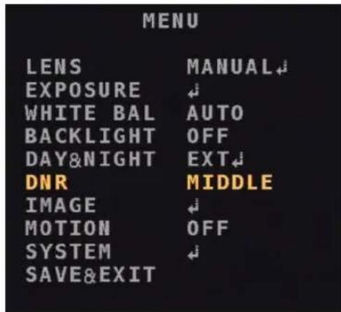
Image Compensation
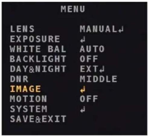
The IMAGE function allows you to optimize the image quality by adjusting various options.
1 From the MENU screen, move the yellow indicator to the IMAGE using the UP or DOWN button.
2 Press the OSD button to display the submenus of the IMAGE.
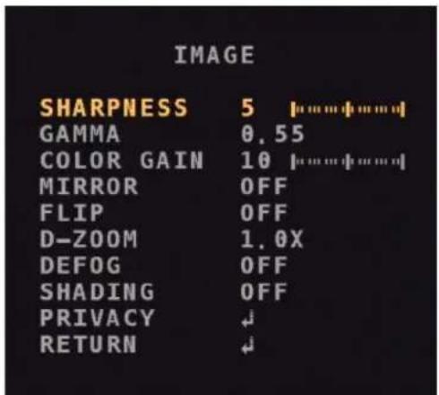
- SHARPNESS: Adjust the sharpness level of the image. (0\~10) Increasing the level makes the screen to be seen sharper.
• GAMMA: Adjust the gamma level of the image. (0.45\~0.75)

The GAMMA does not work while the WDR MODE in the BACK LIGHT menu is used.
- COLOR GAIN: Adjust the color gain value of the image. (0\~20)
- MIRROR: The image on the screen is inverted horizontally.
-
FLIP: The image on the screen is inverted vertically.
-
D-ZOOM: You can enable the camera to perform digital zooming. The magnifying power value is adjustable from 1.0x to 16.0x. Increasing magnifying power value makes the resolution lower.
- DEFOG: If the screen is not clear due to fog, yellow dust, and moisture, you can allow the camera to eliminate the distraction. Select ON to load the submenus and set up the MODE (AUTO/MANUAL) and the LEVEL (LOW/MIDDLE/HIGH).

The DEFOG does not work while the WDR MODE in the BACK LIGHT menu is used.
- SHADING: If the lens is set to a very wide angle, a contrast effect works. Select ON to load the submenus and adjust WEIGHT (0\~100%). This will have an effect in the middle and on the edge of the screen.
- PRIVACY: You can cover a certain area of the screen. The zone can be adjusted in the shape of BOX or POLYGON.
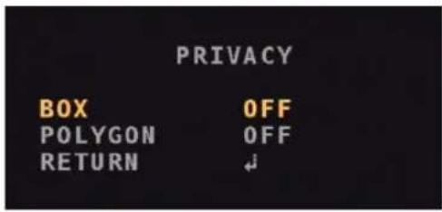
BOX
Select the applying zone in the shape of box.
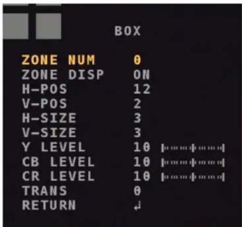
- ZONE NUM: Select the box. (0\~15)
- ZONE DISP : Choose the state of the box. (ON/OFF)
- H-POS: Adjust the horizontal start position. (0\~80)
- V-POS: Adjust the vertical start position. (0\~61)
- H-SIZE: Adjust the horizontal size of the zone. (0\~80)
- V-SIZE: Adjust the vertical size of the zone. (0\~61)
- Y LEVEL: Adjust the brightness of the zone. (0\~20)
- CB LEVEL: Adjust the blue color range of the zone. (0\~20)
- CR LEVEL: Adjust the red color range of the zone. (0\~20)
- TRANS: Adjust the transparency of the zone. (0\~3)

The maximum of the adjustable values may vary depending on the resolution.
POLYGON
Select the applying zone in the shape of polygon. The four vertexes can be moved in order to adjust a range.
![POLYGON ZONE NUM 0 ZONE DISP ON POS0-X 80 POS0-Y 5 POS1-X 88 POS1-Y 5 POS2-X 88 POS2-Y 13 POS3-X 80 POS3-Y 13 Y LEVEL 10 [......] CB LEVEL 10 [......] CR LEVEL 10 [......] TRANS 2 RETURN ↓](/content/2026/06/1182529/images/fba9cf2e078554288cbff4fa1ba705e924951dbfc5b4b258ddb7125daf43479f.jpg)
- ZONE NUM: Select the polygon. (0\~7)
- ZONE DISP : Choose the state of the polygon. (ON/OFF)
- POS0-X: Adjust the vertex of the X-coordinate at the top left. (0\~162)
- POS0-Y: Adjust the vertex of the Y-coordinate at the top left. (0\~122)
- POS1-X: Adjust the vertex of the X-coordinate at the top right. (0\~162)
- POS1-Y: Adjust the vertex of the Y-coordinate at the top right. (0\~122)
- POS2-X: Adjust the vertex of the X-coordinate at the bottom left. (0\~162)
- POS2-Y: Adjust the vertex of the Y-coordinate at the bottom left. (0\~122)
- POS3-X: Adjust the vertex of the X-coordinate at the bottom right. (0\~162)
- POS3-Y: Adjust the vertex of the Y-coordinate at the bottom right. (0\~122)
- Y LEVEL: Adjust the brightness of the zone. (0\~20)
- CB LEVEL: Adjust the blue color range of the zone. (0\~20)
- CR LEVEL: Adjust the red color range of the zone. (0\~20)
- TRANS: Adjust the transparency of the zone. (0\~3

The maximum of the adjustable values may vary depending on the resolution.
Motion Detection
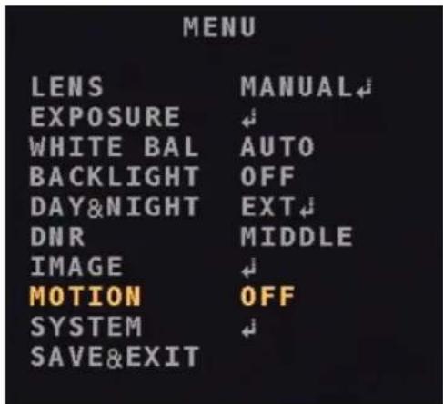
The MOTION function enables the camera to detect moving objects.
1 From the MENU screen, move the yellow indicator to the MOTION using the UP or DOWN button.
2 Press the L or R button to select ON to load submenus and set up details.

Before setting of the motion detection area(DET WINDOW), select ON at MOTION OSD, the submenu of the MOTION. If it is set to OFF, the motion detection area does not appear.
![MOTION DET WINDOW ↓ SENSITIVITY 5 [......] MOTION OSD OFF TEXT ALARM OFF SIGNAL OUT NOT USED RETURN ↓](/content/2026/06/1182529/images/3573b9f4315b98768eb42d19abb67f230a8f8449c6ef84ce2fedbe93f5a0de01.jpg)
• DET WINDOW: Set up the area of motion detection
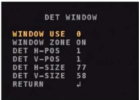
- WINDOW USE: Select the detection window. (0\~3)
- WINDOW ZONE: Choose the state of the detection window. (ON/ OFF)
- DET H-POS: Adjust the starting point of the window to the left or right. (0\~80)
- DET V-POS: Adjust the starting point of the window up or down. (0\~60)
- DET H-SIZE: Adjust the horizontal size of the zone. (0\~80)
- DET V-SIZE: Adjust the vertical size of the zone. (0\~60)

The maximum of the adjustable values may vary depending on the resolution.
- SENSITIVITY: Increasing the sensitivity level makes the motion detection more sensitive, but the resolution may be reduced. (0\~10)
- MOTION OSD: Display the detection window on the screen. (ON/ OFF)
- TEXT ALARM: When the camera detects a moving object, texts will be displayed on the screen.(ON/OFF)
• SIGNAL OUT: This feature is not supported.
System
Additional settings can be specified at SYSTEM.
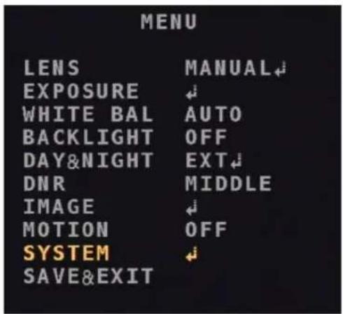
1 From the MENU screen, move the yellow indicator to the SYSTEM using the UP or DOWN button.
2 Press the OSD button to display the submenus of the SYSTEM.
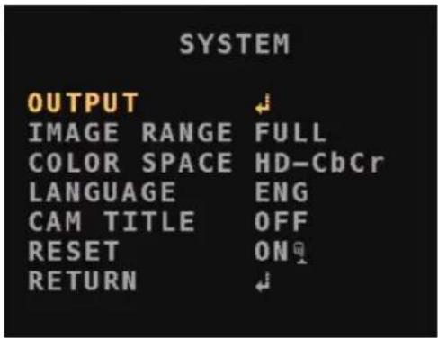
- OUTPUT: Change settings related to the video output.
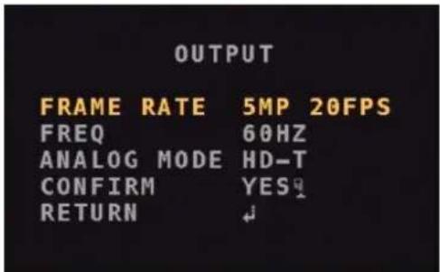
- FRAME RATE: Select a frame that is linked to the resolution. (2MP 30FPS/5MP 12.5FPS/5MP 20FPS/4MP 30FPS)
- FREQ: Choose PAL(50HZ) or NTSC(60HZ). (50HZ/60HZ)
- ANALOG MODE: Select the analog output format. (HD-T/HD-A/CVBS)

The FRAME RATE will be inactivated when CVBS is selected.
- CONFIRM: Press the OSD button during three seconds, then a message, PUSHING, appears with the OUTPUT setting applied.
- IMAGE RANGE: This is a function that adjusts brightness of the screen and color expression. Select one of the following: FULL, COMP, and USER. (FULL=100%/COMP=75%). If you select USER, you can randomly designate the value at OFFSET. The higher the value, the brighter the screen, and also the more blurred the impression of colors. (0\~32)
- COLOR SPACE: Select the impression of a color on the screen. (YUV/SD-CbCr/HD-CbCr)
- LANGUAGE: Select one of the languages. (ENG/CHN/CHN[S]/JPN/KOR)
Part 1 - Menu Setup
- CAM TITLE: Display the name of the camera in a certain area of the screen. (OFF/RIGHT UP/LEFT DOWN) After selecting the area, press OSD button to name the camera.
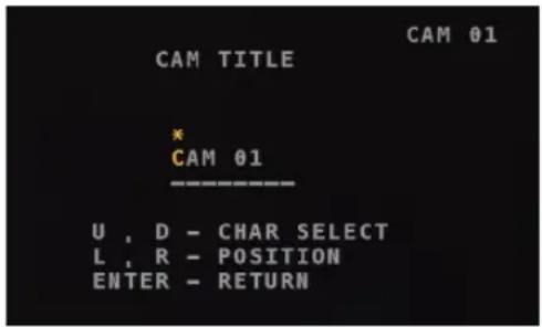
- U, D - CHAR SELECT: You can choose a letter using the UP or DOWN button.
- L, R - POSITION: You can move to a certain position of the character string.
- ENTER: After completing the setting, press the OSD button.
- RESET: You can restore the camera to its factory default settings. Press the OSD button during three seconds to reset the camera.
Save & Exit
Press SAVE&EXIT button to save the settings and exit.
IDIS®
- Before reading this manual
- Safety Precautions
- WARNING
- Important Safeguards
- Read Instructions
- Retain Instructions
- Cleaning
- Attachments
- Water and/or Moisture
- Placing and Accessories
- Power Sources
- Power Cord
- Lightning
- Overloading
- Objects and Liquids
- Servicing
- Damage requiring Service
- Replacement Parts
- Safety Check
- Field Installation
- 17.Tmra
- FCC Compliance Statement
- WEEE (Waste Electrical & Electronic Equipment)
- Correct Disposal of This Product
- (Applicable in the European Union and other European countries with separate collection systems)
- Copyright
- Registered Trademarks
- Table of Contents
- 1
- Part 1 - Menu Setup
- Lens
- Exposure Compensation
- White Balance
- Backlight Compensation
- POLYGON
- Day&Night Function
- Dynamic Noise Reduction
- Image Compensation
- Motion Detection
- System
- Save & Exit
- IDIS®
Brand : IDIS
Model : TC-D5511RX
Category : Surveillance Camera