VT-EHL4 - Uncategorized Vitek - Free user manual and instructions
Find the device manual for free VT-EHL4 Vitek in PDF.


| Product Type | Digital Video Recorder (DVR) for Security Surveillance |
| Model | VT-EHL4 |
| Brand | Vitek |
| Video Inputs | 4 Channels (BNC) |
| Video Outputs | 1 Main BNC, 1 Spot BNC, 1 VGA |
| Video Compression | H.264 |
| Recording Resolution | Up to 704x480 (D1) at 60 fps total |
| Audio | 4 Audio Inputs, 1 Audio Output |
| Alarm | 4 Alarm Inputs, 1 Relay Output |
| PTZ Control | Yes, via RS-485 |
| Remote Access | Internet, LAN, Web Browser (IE, Firefox, Chrome, Safari), Smartphone Apps (iPhone, iPad, Android) |
| Storage | Internal HDD up to 2TB (one drive) |
| Power Supply | 12V DC, 3.33A adapter |
| Power Consumption | Approx. 40W (estimated) |
| Dimensions (WxDxH) | Not specified (typical standalone DVR) |
| Weight | Not specified |
| Operating Temperature | Max 40°C (104°F) |
| Care & Cleaning | Shut down and disconnect power before cleaning. Use soft dry cloth only; no abrasive cleaners. |
| Safety Instructions | Read all instructions, keep away from water, do not block ventilation, avoid heat sources, use only specified attachments, unplug during storms or long idle, refer servicing to qualified personnel. |
| Spare Parts & Repairability | No user-serviceable parts; contact service center for repairs. |
Frequently Asked Questions - VT-EHL4 Vitek
User questions about VT-EHL4 Vitek
0 question about this device. Answer the ones you know or ask your own.
Ask a new question about this device
Download the instructions for your Uncategorized in PDF format for free! Find your manual VT-EHL4 - Vitek and take your electronic device back in hand. On this page are published all the documents necessary for the use of your device. VT-EHL4 by Vitek.
USER MANUAL VT-EHL4 Vitek
• 4 or 8 Video Inputs with 1 Main, 1 Spot Monitor Output and 1 VGA output.
• H.264 Compression
• Supports both Dynamic and Static IP Addresses
• 4 Alarm Inputs / 1 Relay Out
• Up to 240 IPS Recording / Live Display (VT-EHL8) / 120 IPS (VT-EHL4)
- Remote Viewing over the Internet, LAN, Explorer, Safari, Firefox, Opera and Chrome
• Applications for iPhone, iPad, iTouch and Droid Devices
- 500GB to 2TB Internal Storage Options (one Internal HDD)
- "Quick Search" Function for automatic review
- Email Event Notification with Snapshot
• CMS Central Management Software (Included)
• Mac OSX Client Software (Included)
• Automatic sending of Health and Event notifications via email
• 4 Audio Inputs & 1 Output
• Control locally via Front Panel, USB Mouse or with the Included IR Remote control
• PTZ Control over RS-485
TABLE OF CONTENTS
System Organization 10
System Configuration 11
Front Panel Description 11
Rear Panel Description 12
Remote Control Description 13
Change the Main Monitor Out 14
Connect and Power On 15
Menu Control 16
Live Display 16
Division Screen 16
Sequence Mode 16
PTZ 17
Digital Zoom 17
Log 18
Panic Recording 18
Quick Menu 19
System Setup 20
Camera 21
Camera Setup 21
Color Setup 21
PTZ Setup 22
PTZ Detail 23
Motion Sensor 24
Display 25
OSD 25
Monitor 26
Sequence 27
Spot Out 29
Sound 30
Audio 30
Buzzer 30
System 31
Date/Time 31
System Management 32
System Information 32
System Names 33
F/W Upgrade 33
Factory Default 33
System Data 33
Password 33
Control Device 33
User 34
User Management 34
User Authority 35
Log Out 35
Network 36
IP Setup 36
DDNS 38
Remote Access 39
E-Mail 42
Event/Sensor 44
HDD Event 44
Alarm Input 44
Alarm Output 44
Buzzer Out 45
E-Mail Notification 46
Disk Management 47
Record Menu
Recording Operations 48
Continuous/Motion Recording 52
Alarm Recording 53
Panic Recording 54
Network Streaming 54
Search
Time Search 55
Multi Playback 57
Event Search 59
Archiving
New Archive 61
Reserved Data Management 62
FTP Setup 62
Web Connection Setup
How to Connect 63
Live Mode 65
Status 66
Log 66
PTZ 67
VT-EHL Series
Search 68
Search by Time 68
Search by Event 69
Setup 70
Camera 70
Display 71
Sound 72
System 72
Recording 73
Network Streaming 74
User 74
Network 74
Sensor 75
Information 75
Backup Player 76
Watermark Process 76
Smartphone Connection
Viewing with the browser
DVR Viewer Guide 80
iPhone/iPad 80
Android 82
Mac Compatibility 88
EH Connect 88
78
78
IMPORTANT SAFETY INSTRUCTIONS
1) Read these instructions.
2) Keep these instructions.
3) Heed all warnings.
4) Follow all instructions.
5) Do not use this apparatus near water.
6) Clean only with a dry cloth.
7) Do not block any of the ventilation openings. Install in accordance with the manufacturer's instructions.
8) Do not install near any heat sources such as radiators, heat registers, stoves, or other apparatus that produce heat.
9) Do not neglect the safety purpose of the polarized or grounding type plug.
A polarized plug has two blades with one wider than the other.
A grounding type plug has two blades and a third grounding prong.
The wide blade or the third prong is provided for your safety.
When the provided plug does not fit into your outlet, consult an electrician for replacement of the obsolete outlet.
10) Protect the power cord from being walked on or pinched particularly at plugs, convenience receptacles, and the point where they exit from the apparatus.
11) Only use the attachments/accessories specified by the manufacturer.
12) Use only with a cart, stand, tripod, bracket, or table specified by the manufacturer, or sold with the apparatus.
When a cart is used, use caution to avoid a tip-over.
13) Unplug this apparatus during lightning storms or when unused for long periods of time.
14) Refer all servicing to qualified service personnel. Servicing is required when the apparatus has been damaged in any way, such as power supply cord or plug is damaged, liquid has been spilled or objects have fallen into the apparatus, the apparatus has been exposed to rain or moisture, does not operate normally, or has been dropped.
15) This equipment is indoor use and all the communication wirings are limited to inside of the building.
16) The socket-outlet shall be installed near the equipment and shall be easily accessible.
17) CAUTION
RISK OF EXPLOSION IF BATTERY IS REPLACED BY AN INCORRECT TYPE.
DISPOSE OF USED BATTERIES ACCORDING TO THE INSTRUCTIONS.
# Operation Max temperature : 40°C
# USB Load condition: USB Ports (5 Vdc, Max. 500 mA)
OVERVIEW

CAUTION
RISK OF ELECTRIC SHOCK. DO NOT OPEN

CAUTION : TO REDUCE THE RISK OF ELECTRIC SHOCK, DO NOT REMOVE COVER (OR BACK) NO USER SERVICEABLE PARTS INSIDE. REFER SERVICING TO QUALIFIED SERVICE PERSONNEL.

This symbol indicates that dangerous voltage consisting a risk of electric shock is present within this unit.

This exclamation point symbol is intended to alert the user to the presence of important operating and maintenance (servicing) instructions in the literature accompanying the appliance.
WARNING
To reduce the risk of fire or electric shock, do not expose this appliance to rain or moisture.
To prevent injury, this apparatus must be securely attached to the floor/wall in accordance with the installation instructions.
1) Be sure to use only the standard adapter that is specified in the specification sheet. Using any other adapter could cause fire, electrical shock, or damage to the product.
2) Incorrectly connecting the power supply or replacing battery may cause explosion, fire, electric shock, or damage to the product.
3) Do not connect multiple cameras to a single adapter. Exceeding the capacity may cause abnormal heat generation or fire.
4) Securely plug the power cord into the power receptacle. Insecure connection may cause fire.
5) When installing the camera, fasten it securely and firmly. A falling camera may cause personal injury.
6) Do not place conductive objects (e.g. screwdrivers, coins, metal parts, etc.) or containers filled with water on top of the device. Doing so may cause personal injury due to fire, electric shock, or falling objects.
7) Do not install the unit in humid, dusty, or sooty locations. Doing so may cause fire or electric shock.
8) If any unusual smells or smoke come from the unit, stop using the product. In such case, immediately disconnect the power source and contact the service center. Continued use in such a condition may cause fire or electric shock.
9) If this product fails to operate normally, contact the nearest service center. Never disassemble or modify this product in any way. (We are not liable for problems caused by unauthorized modifications or attempted repair.)
10) When cleaning, do not spray water directly onto parts of the product. Doing so may cause fire or electric shock.
11) Do not expose the product to the direct airflow from an air conditioner.
OVERVIEW
CAUTION
1) Do not drop objects on the product or apply strong blows to it. Keep away from a location subject to excessive vibration or magnetic interference.
2) Do not install in a location subject to high temperature (over 50^ C), low temperature (below -10^ F), or high humidity. Doing so may cause fire or electric shock.
3) If you want to relocate the already installed product, be sure to turn off the power and then move or reinstall it.
4) Remove the power plug from the outlet when there is a lighting storm. Neglecting to do so may cause fire or damage to the product.
5) Keep out of direct sunlight and heat radiation sources. It may cause fire.
6) Install it in a place with good ventilation.
7) Avoid aiming the camera directly towards extremely bright objects such as sun, as this may damage the CCD image sensor.
8) Apparatus shall not be exposed to dripping or splashing and no objects filled with liquids, such as vases, shall be placed on the apparatus.
9) The Mains plug is used as a disconnect device and shall stay readily operable at any time.
10) When using the camera outdoors, moisture may occur inside the camera due to temperature difference between indoors and outdoors. For this reason, it is recommended to install the camera indoors. For outdoor use, use the camera with built-in fan and heater.
11) Risk of explosion if battery is replaced by an incorrect type. Dispose of used batteries according to the instructions.
12) LAN Ethernet cable should not be extended to outside of building.
BEFORE INSTALLATION
● Installation should be carried out only by qualified personnel and in accordance with any electrical regulations in force at the time.
● The DVR must be placed on a stable surface or mounted in an approved cabinet. Adequate ventilation must be provided, taking particular care not to block any of the air vents on the DVR.
● Adequate protection against lightning strikes and power surges must be installed to prevent damage to the DVR.
● Any safety warnings on the DVR and in these instructions must be adhered to.
- If cleaning is necessary, shutdown the DVR and disconnect power first. Use a soft dry cloth only; never use any abrasive cleaners.
- Do not attempt to service or repair the DVR as opening or removing covers may expose dangerous voltages or other hazards.
Refer all servicing to qualified service personnel.
MAIN FEATURES
MOUSE CONTROL
Designed to be controlled and easy to use with a mouse.
ENHANCED GRAPHICAL USER INTERFACE [GUI]
The DVR menu structure and on screen display is presented in a simple to use and logical GUI format.
The 8 Channel DVR is Triplex (Simultaneous Live, Record, Network), and the 4 Channel DVR is Quadruplex (Simultaneous Live, Record, Network, and Playback).
AUDIO
4 audio inputs are supported which can be assigned to any video channel. Live and recorded audio can be monitored remotely over the internet and remote 'talkback' audio transmission to the DVR is also possible.
BACKUP
Recorded footage (including audio) can be archived to USB memory stick, or to your computer through network connection.
Playback software is embedded with the backup files and the backup also contains the system event log and backup log for full traceability.
REMOTE CONNECTION
Depending on the user level, full DVR control is available over the internet as well as the ability to remotely configure the DVR. Alarm outputs on the DVR can be remotely triggered over the internet.
COMPREHENSIVE RECORDING SETUP
Recording can be scheduled, alarm or motion activated. For each type of recording, frame rates, image quality and audio recording properties can be adjusted per hour, day and for each individual channel.
The DVR also has a panic recording feature (from the front panel or external input) which overrides all other recording settings to provide the best quality recording in the event of an emergency.
PTZ CONTROL
Full PTZ control is available from the front panel or remote connection and a wide number of speed dome protocols are supported. Protocols can be set individually for each channel and PTZ speed can be adjusted to suit particular speed domes.
MAIN FEATURES
TELEMETRY CONTROL
Full telemetry control is available from the front panel or remote connection and a wide number of speed dome protocols are supported. Protocols can be set individually for each channel and telemetry speed can be adjusted to suit particular speed domes.
EXTENSIVE MONITOR SUPPORT
The DVR has 2 main monitor outputs (Composite and VGA).
One spot monitor output can be programmed in the DVR setup.
LIVE DISPLAY
The DVR displays single or multi screen images and also has several sequence modes (standard and user definable).
All configuration settings on the DVR can be saved to USB memory stick or a PC files remotely.
The saved data can then be uploaded to other DVR units allowing rapid deployment where more than one DVR is being installed.
EMAIL SUPPORT
The DVR can send emails to specific users to notify events such as alarm, motion detection, hard drive failure, & etc.
SYSTEM ORGANIZATION
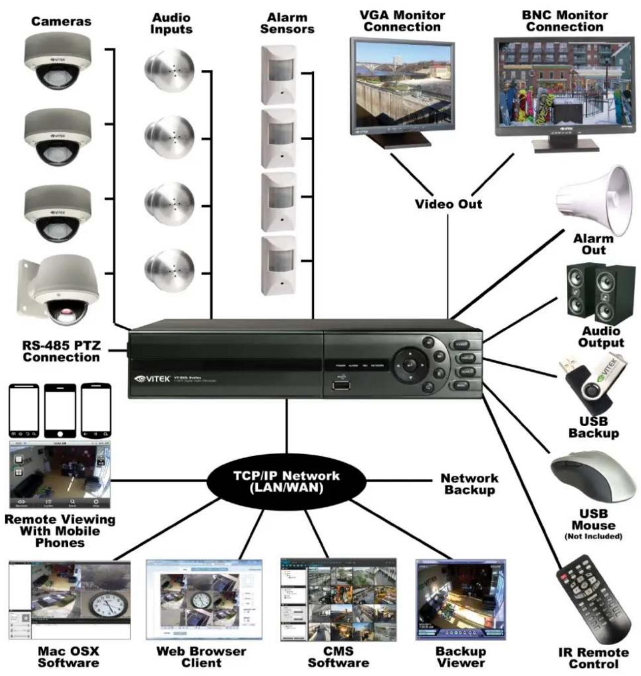
flowchart
graph TD
    A["Cameras"] --> B["RS-485 PTZ Connection"]
    C["Audio Inputs"] --> B
    D["Alarm Sensors"] --> B
    E["VGA Monitor Connection"] --> F["Video Out"]
    G["BNC Monitor Connection"] --> F
    H["Alarm Out"] --> I["USB Backup"]
    J["Audio Output"] --> I
    K["Remote Viewing With Mobile Phones"] --> L["TCP/IP Network (LAN/WAN)"]
    M["Network Backup"] --> L
    N["Mac OSX Software"] --> L
    O["Web Browser Client"] --> L
    P["CMS Software"] --> L
    Q["Backup Viewer"] --> L
    R["USB Mouse (Not Included)"] --> L
    S["IR Remote Control"] --> L
1. Front panel description.
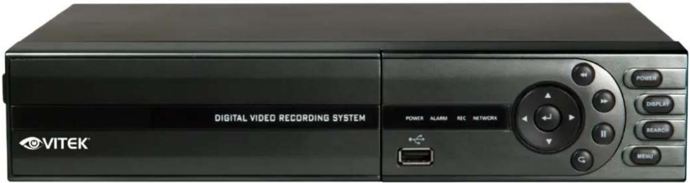
| KEY | DESCRIPTION |
| Function Key | |
| POWER | Turn On/Off the system power |
| DISPLAY | Selects various display modes in live display and playback |
| MENU | Displays the setup menus |
| SEARCH | Displays the search menu |
| Control Key | |
| CURSOR KEYS | Allow to Navigate on the menu |
| ENTER | Apply or Select an item |
| RETURN | Cancel or go to Previous menu |
| Playback Control | |
| ◀◀ | Increases reverse playback speed |
| ◀ | Selects reverse playback |
| ▶ / II | Selects forward playback and also accesses the instant playback feature and Pauses / resumes playback |
| ▶▶ | Increases forward playback speed |
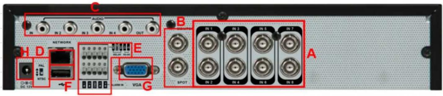
2. Rear panel description.
8 Channel
4 Channel
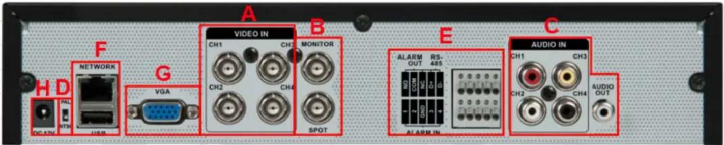
A. CAMERA INPUT: Connect up to 8 camera inputs.
B. MONITOR: Main BNC monitor.
SPOT OUT : BNC Spot monitor.
C. AUDIO INPUTS & OUTPUTS: Up to 4 audio inputs and one audio output can be connected as necessary.
D. PAL / NTSC : Change Camera input type.
E. ALARM INPUTS: Up to 4 alarm inputs can be connected and configured as high or low inputs with common ground.
RELAY OUTPUT : 1 alarm output can be connected and configured as high or low output with common ground.
RS485 : Connect PTZ camera.
F. LAN : LAN connection to a router or internal network.
USB : you can connect USB mouse or USB memory.
G. VGA : VGA main monitor connection to a PC monitor or plasma screen.
H. POWER : Connect 12V / 3.33A adaptor.
Remote Control
3. Remote Control description.
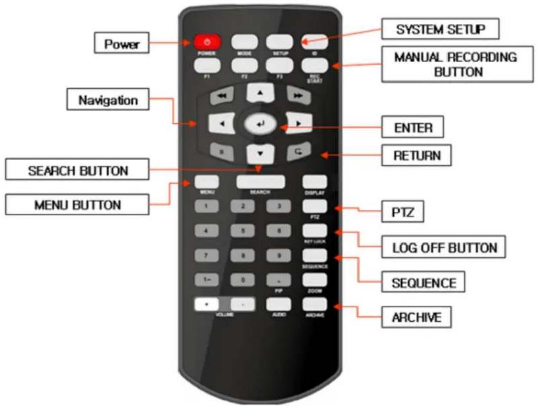
※ If there are many DVRs on a stack, each DVR must be set with a different ID. You can do this here: Menu/System Setup/Main/System/Control Device. From the remote controller sync the remote to each DVR, then all DVRs can be controlled with one remote controller.
How to sync a remote controller to a DVR's ID
Press the ID button on the remote. Notice REMOTE ID statement on the screen.
On the remote controller, enter the System ID number, press ENTER, then press RETURN.
(default System ID is 0)
Changing the Main Monitor Output
- The system supports only 1 main monitor out at a time; you must select either VGA or BNC.
- You can select the main monitor out by using the buttons on the front panel.
There are two ways to switch the monitor output
1) Press DISP + RETURN key on Front Panel during Boot on system.
2) Press DISP + RETURN + DISP + RETURN key on remote controller sequentially during boot on system
Below images are the screens of Main monitor out and Sub monitor out
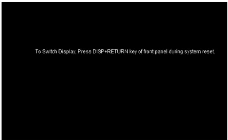
*Selected Sub monitor out
natural_image
A single blue horizontal bar on a white background, no text or symbols present.*Selected Sub monitor out
CONNECT & POWER ON
- Connect up to 8 CAMERA INPUTS as necessary.
- Connect monitors to the DVR using the COMPOSITE or VGA connections
- Connect power to the DVR. The DVR checks for proper power connection and emits two beeps.
Press the POWER BUTTON on the front panel of the DVR to begin operation.
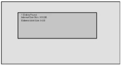
The DVR startup screen detects and checks the status of the hard drive.
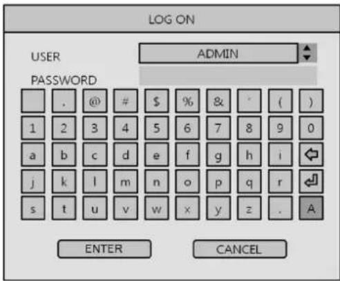
After startup diagnostics are complete, the operator must logon to the system. The default user name is 'ADMIN'.
Using the Virtual keyboard, key in
the default password as '1234' and press the ENTER button.
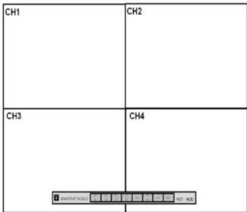
The DVR begins normal operation and shows the default display of all 4 or 8 channels depending on system model.
The status bar (Including menu control) is shown at the bottom of the screen
The indicator for each channel is shown.
The red square and letter 'C' in the top right of each channel display shows that the channel is recording in Continuous / Schedule mode.
MENU CONTROL

All menus can be controlled from above 'Status Bar' with mouse or front panel buttons.
LIVE DISPLAY
DIVISION SCREEN
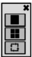
Select the 'DISPLAY' button and screen division menu will appear. Select the screen type (1, 4, 6, and 8 rotation sequence).
Sequence mode
Press the SEQ button. Each channel is shown in full screen for a set period of time before switching to the next channel.
To stop the sequence on a particular channel, press the SEQ button again. More complex sequences can be programmed through the setup menu

LIVE DISPLAY
PTZ
Digital Zoom
Select the "ZOOM" button.

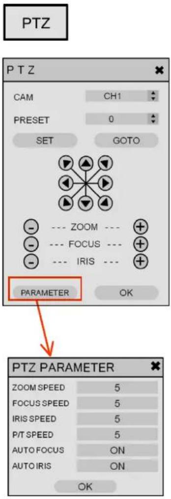
1) CAM: Select the desired camera Channel
2) Presets: To Program a preset, move the camera to the desired field of view with the directional arrows, then choose the desired preset to be used, then select SET.
3) Moving to Preset: Select the preset you wish the camera to move to, then select GO TO
4) Zoom, Focus, IRIS: User can control each item with + or - button.
5) Parameter: Press this button and another window will appear.
User can select each item from PTZ parameter menu.
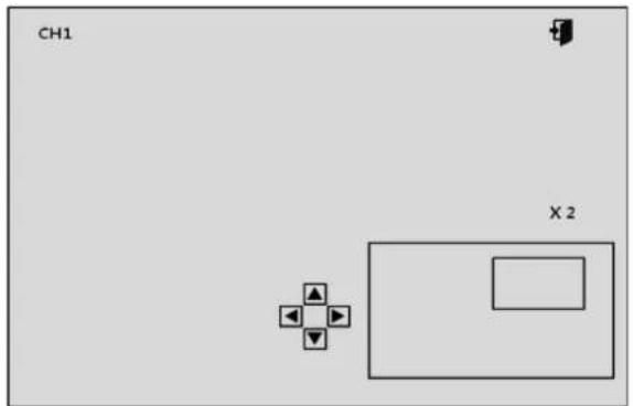
When viewing a channel in full screen, the operator can zoom in to a particular area by up to 14 times.
To use the digital zoom, select the required channel and press the ZOOM button.
LIVE DISPLAY
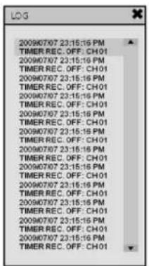
Displays all system and event logs.

Panic Recording
This menu is used to start and stop the Panic recording.
If the panic recording is started, record icon will change to red square with "P".
Select once more to return to previous record schedule.
- Panic recording setup will be assigned from the Record menu.
LIVE DISPLAY
Quick Menu
flowchart
graph LR
    A["PTZ"] --> B["ZOOM"]
    B --> C["PLAYBACK >"]
    C --> D["PANIC REC START"]
    E["PTZ"] --> F["ZOOM"]
    F --> G["PLAYBACK >"]
    G --> H["PANIC REC START"]
    I["10sec ago"] --> J["20sec ago"]
    J --> K["30sec ago"]
    K --> L["1min ago"]
    L --> M["Go to"]
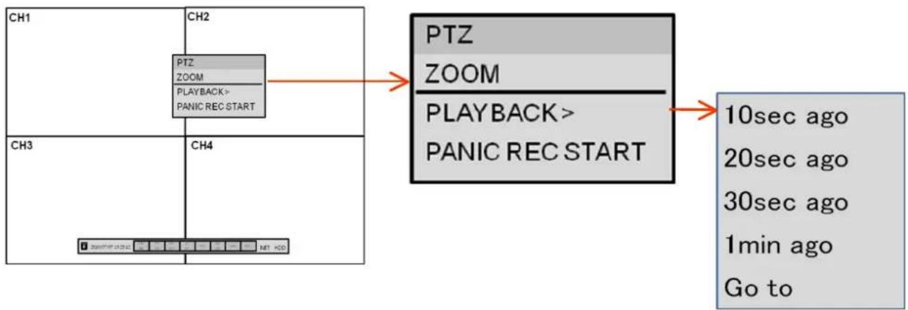
User can use quick menu by right-clicking the mouse at each live channel
- PTZ
Please refer to "PTZ" menu of Page 14.
- ZOOM
Please refer to "ZOOM" menu of Page 14.
- Playback
Your can start instant playback on floating window during live surveillance.
- PANIC REC START (Stop)
Please refer to "Panic record" menu of Page 15.
SYSTEM SETUP
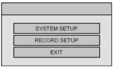
Click the "MENU" and click the SYSTEM SETUP menu.
flowchart
graph TD
    A[" "] --> B["SYSTEM SETUP"]
    B --> C["RECORD SETUP"]
    C --> D["EXIT"]
SYSTEM SETUP MENU

CAMERA

DISPLAY

SOUND

SYSTEM

USER

NETWORK

EVENT/SENSOR

DISK
To navigate around any items in the setup menu, use the CURSOR KEYS and the ENTER and RETURN buttons.
In general, the ENTER button is used to select and change a particular item and the RETURN button is used to cancel a change or exit from a particular setup screen.
To setup all main system functions, highlight SYSTEM SETUP and press ENTER.
SYSTEM SETUP
CAMERA
Click the CAMERA menu.
To setup the various camera options, highlight CAMERA and press ENTER.
TITLE: Input the camera title.
COVERT: When it is set to ON, the camera image is not displayed in live display but continues to record.
AUDIO: Determines the audio recording channel.
CAMERA : COLOR SETUP
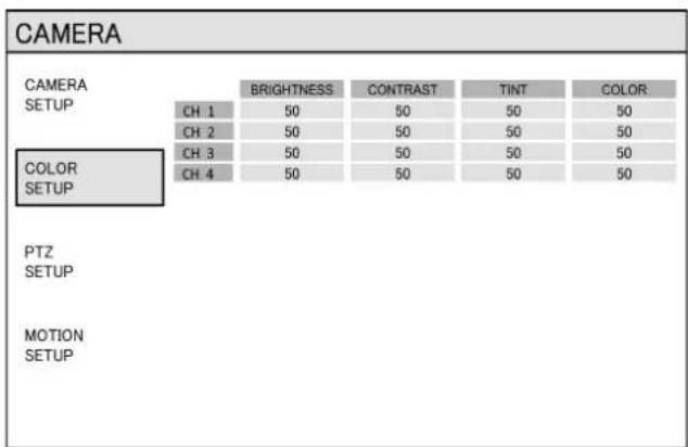
Brightness, contrast, tint and color can be adjusted for each individual channel.
Highlight each channel to modify and press ENTER.
SYSTEM SETUP
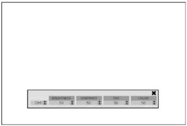
Click each value with button.
The selected channel is displayed in full screen.
BRIGHTNESS, CONTRAST, TINT and COLOR can be changed as necessary.
To modify a different channel, highlight CAMERA and choose the desired channel.
Press RETURN when all changes are complete.
CAMERA : PTZ SETUP
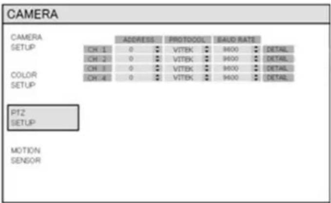
Click the PTZ SETUP menu and click each value on the ADDRESS, PROTOCOL and BAUD RATE menu.
Change each value with button.
ADDRESS : The unique ID of the PTZ device.
PROTOCOL : The protocol of the PTZ device.
BAUD RATE : The baud rate of the PTZ device.
DETAIL : Detail setting for PTZ device. (Refer to the next page)
SYSTEM SETUP
DETAIL
| PTZ PROPERTY | ||
| CHANNEL No. | 1 | |
| PTZ DRIVER | VITEK | |
| AUTO FOCUS | ON | ▲ |
| AUTO IRIS | ON | ▲ |
| P/T SPEED | 5 | ▲ |
| ZOOM SPEED | 5 | ▲ |
| FOCUS SPEED | 5 | ▲ |
| IRIS SPEED | 5 | ▲ |
| OK | ||
Click the "DETAIL" button and change the detail value with

button.
Note that some settings, such as AUTO FOCUS, may not be compatible with particular PTZ equipment. If this is the case, changing the value will have no effect on PTZ control.
SYSTEM SETUP
CAMERA : MOTION SENSOR
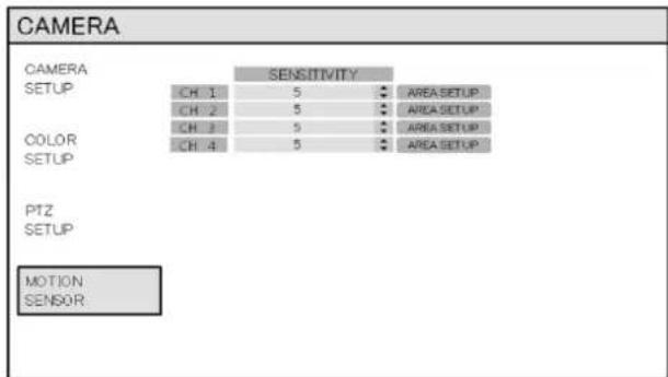
Click the MOTION SENSOR menu and click the value on the SENSITIVITY menu.
Change the value with button.
SENSITIVITY : Between 1 (Lowest) and 10 (Highest) and determines the degree of motion required before recording is activated.
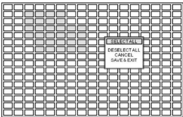
Click the
AREA SETUP
button.
AREA SETUP : Choosing this option allows the operator to define which areas of the image are monitored for motion detection.
For quick select or deselect the entire grid, click the right mouse button and click the SELECT ALL or DESELECT ALL menu.
- Blank/clear area: Non selected area
- Yellow grid-like boxes: Selected area
SYSTEM SETUP
DISPLAY
To setup the various display options, highlight DISPLAY and press ENTER.
DISPLAY - OSD
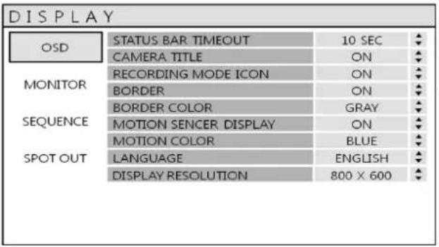
Click the OSD menu.
Then click the button for ON/OFF and change the value.
STATUS BAR: Determines how long before status bar time outs.
CAMERA TITLE: Determines whether the camera title is displayed.
RECORDING MODE ICON: Determines whether the DVR recording status is shown at the top right of each channel display window.
BORDER: Determines whether there is a border around each channel in multi screen display mode.
BORDER COLOR: If the border is ON, the operator can choose the color.
MOTION SENSOR DISPLAY: If false motion recording is occurring, the operator can use this feature to determine and rectify the cause in real-time.
OFF – normal display mode.
ON – areas where motion is detected are highlighted with colored blocks.
MOTION COLOR: The color of the blocks displayed when MOTION SENSOR DISPLAY is set to ON.
LANGUAGE: Determines the language type.
DISPLAY RESOLUTION: Determines the resolution of VGA out only.
SYSTEM SETUP
DISPLAY : MONITOR
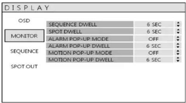
Click the MONITOR menu
Then click the button for ON/OFF and change the value
SEQUENCE DWELL : The time each screen is displayed in a sequence operation.
SPOT DWELL : The time each screen is displayed on the spot monitor outputs.
ALARM POP-UP MODE : When set to ON, an alarm input will cause the associated channel to display in full screen.
ALARM POP-UP DWELL : Determines how long the full screen popup is displayed after an alarm input. If the alarm condition continues, the popup screen is displayed constantly.
MOTION POP-UP MODE : When set to ON, motion detection will cause the associated channel to display full screen.
MOTION POP-UP DWELL : Determines how long the full screen popup is displayed after motion detection. If motion continues, the popup screen is displayed constantly.
SYSTEM SETUP
DISPLAY : SEQUENCE
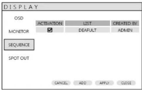
Click the SEQUENCE menu.
When the SEQ button is pressed, the default sequence will cycle through 4 or 8 channels (depending on DVR model), one by one.
Sequence setup allows the operator to define a custom sequence, using mixed multi screen views and any desired channels.
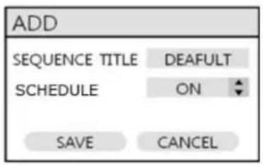
Click the ADD menu.
To add a new sequence, highlight ADD and press ENTER.
Sequence title is highlighted – press ENTER to bring up the virtual keyboard and key in a name or reference number for the new sequence.
Click on the SCHEDULE tab and click button for select ON/OFF.
Select the SAVE. Then, below menu will appear.
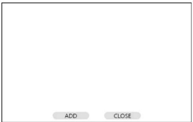
SYSTEM SETUP
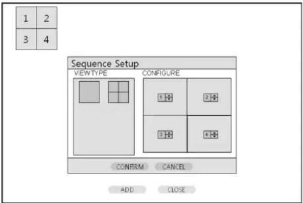
Press ADD. Then, "Sequence Setup" menu appears.
Determine the "VIEW TYPE" and assign "CONFIGURE". Then, click CONFIRM.
To add an additional mode, click ADD continuously. After finishing the setup, press CLOSE.
To modify the current one, double click that mode. Then 'Sequence Setup' window will appear again.
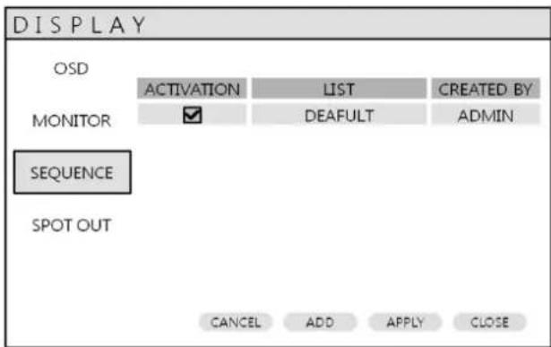
The new sequence is now saved and can be started by pressing the SEQ button when in live view.
SYSTEM SETUP
DISPLAY : SPOT-OUT
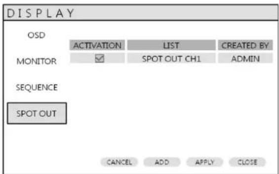

Click the SPOT-OUT menu and click the camera channel for ON/OFF.
The DVR has 1 SPOT MONITOR OUTPUT (Analog Spot).
Double click the spot out channel for modification.
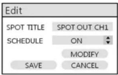
SPOT TITLE: input the title.
SCHEDULE: Determines ON/OFF.
Press MODIFY. (Below is default setup)
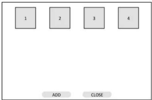
To modify the current display, double click the display. Then "Spot Sequence Setup" window will appear.
How to setup is same as Sequence setup. (User can assign Single display only)
To add the additional display, press ADD.
flowchart
graph TD
    A["1"] --> B["2"]
    B --> C["3"]
    C --> D["4"]
    E["ADD"] --> F["CLOSE"]
SYSTEM SETUP
SOUND
Click the SOUND menu.
To setup the various sound options, highlight SOUND and press ENTER
SOUND : AUDIO
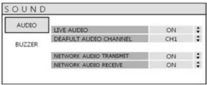
Click the AUDIO menu and click the ON/OFF menu.
Then, click the button for ON/OFF.
LIVE AUDIO : When it is set to ON, the selected audio channel can be monitored on the AUDIO OUTPUT.
DEFAULT CHANNEL : Specify which one of the 4 AUDIO INPUTS is routed to the AUDIO OUTPUT.
NETWORK AUDIO TX : When set to ON, live and playback audio is transmitted to a remote PC connection.
NETWORK AUDIO RX : When set to ON, allows a remote PC connection to send audio back to the DVR.
SOUND : BUZZER
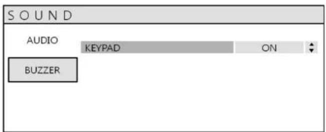
Click the BUZZER menu and click the ON/OFF menu.
Then, click the button for ON/OFF.
KEYPAD: When it is set to ON, each front panel button press is confirmed by a beep.
SYSTEM SETUP
SYSTEM
Click the SYSTEM menu.
To setup the various system options, highlight SYSTEM and press ENTER.
DATE / TIME
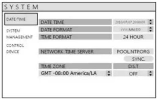
Click the DATE / TIME menu.
DATE TIME : Allows the operator to set or modify the current date & time.
DATE FORMAT : Determines how the date is displayed.
TIME FORMAT : Determines how the time is displayed.
NETWORK TIME SERVER : If the DVR is connected to the Internet, the time and date can be accurately set by selecting SYNC and pressing ENTER.
TIME ZONE : It should be set according to the region, which the DVR is used in.
D.S.T: When it is set to ON, the DVR will automatically adjust the time by one hour on the relevant date in spring and autumn.
SYSTEM SETUP
SYSTEM : SYSTEM MANAGEMENT
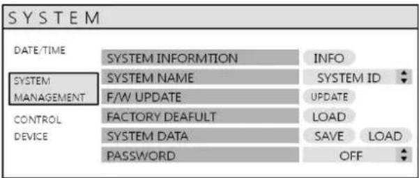
Click the SYSTEM MANAGEMENT menu.
SYSTEM INFORMATION: User can see the system information as below.
| SYSTEM INFORMATION | |
| F/W VERSION | FIRM WARE Ver. |
| H/W VERSION | HARDWARE ID |
| VIDEO SIGNAL TYPE | NTSC |
| DISK CAPACITY | 244 GB |
| IP ADDRESS | 192.168.1.1 |
| MAC ADDRESS | 0000000000000 |
| DDNS DOMAIN NAME | DVRLINK.NET |
| RTSP SERVICE PORT | 554 |
| WEB SERVER PORT | 8080 |
F/W VERSION : Shows the firmware version of the DVR.
H/W VERSION : Shows the hardware version of the DVR.
VIDEO SIGNAL TYPE : The DVR automatically switches between PAL and NTSC depending on the channel 1 input signal at power on.
DISK CAPACITY : The first value shows the total hard drive capacity installed.
IP ADDRESS : Shows either the manual IP address entered in NETWORK setup or the IP address assigned by a DHCP server if enabled.
MAC ADDRESS : Shows the MAC (Media Access Control) address of the DVR.
It is unique – no other network device has this MAC address.
DDNS DOMAIN NAME : If DDNS is enabled, the host DDNS server is specified here.
RTSP SERVICE PORT: The port number that the DVR uses to support remote connection from the client software.
WEB SERVER PORT: The port number that the DVR uses to support remote connection from Internet Explorer or other web browsers.
SYSTEM SETUP
SYSTEM NAME : It is used so that notification emails can be identified.
F/W UPDATE : Firmware updates may be released periodically to enhance system performance and add extra features.
The operator must upgrade the firmware using a USB memory stick. The firmware is available for download on the Vitek website http://vitekcctv.com/Downloads.asp . Once the firmware has been downloaded, extract the firmware from the zip folder and put it onto a USB stick.
After inserting the USB stick (with firmware on it) into the DVR, Press UPDATE.
The following menu will appear:
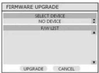
After selecting the F/W from F/W list, press UPGRADE. Then, F/W upgrade is started.
FACTORY DEFAULT : If settings have been changed, which cause erratic behavior, the factory default settings can be loaded.
SYSTEM DATA : System settings can be saved to a USB memory stick. The settings can be reloaded in case of accidental factory reset or can be transferred to another DVR if multiple units need to be installed with the same settings. All information is saved apart from network settings and system name.
PASSWORD : Determines the PASSWORD ON/OFF to enter specific menu.
SYSTEM : CONTROL DEVICE
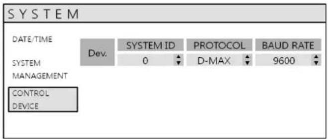
This will allow up to 254 DVRs to be controlled by the same remote.
SYSTEM ID : If more than one DVR is connected on the same RS485 bus, each one must have a unique ID.
Note : If using more than one DVR on stack, each DVR must have a unique ID for control by remote controller.
PROTOCOL : Must be set by Control Device.
BAUD RATE : Must be set to match the baud rate of the controller.
SYSTEM SETUP
USER
Click the USER menu.
To setup the various system options, highlight USER and press ENTER.
USER : USER MANAGEMENT
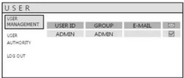
By default, the DVR is configured with a user ID of ADMIN, belonging to the ADMIN group and with a password of 1234.
As well as the ability to add new users, existing user details can be modified.
To modify user details, highlight the user with the green cursor and press ENTER.
The maximum number of users that can be created is 8.
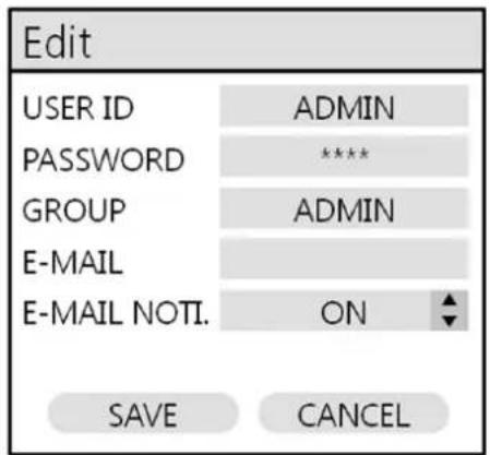
To EDIT an account select it with a double mouse click or use the control keys. After changing, click OK.
USER ID : Edit the user ID using the virtual keyboard. (Max. 10 characters)
PASSWORD : Change the password using the virtual keyboard. (Max. 4 Characters)
GROUP : Users can be assigned to one of three groups - ADMIN, MANAGER or USER.
E-MAIL : Enter the user's email address if email notification is required. (Max. 64 Characters)
E-MAIL NOTIFICATION : Enable or disable email notifications for the specified user.
SYSTEM SETUP
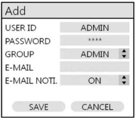
To ADD a user, select ADD at the bottom then select OK.
USER ID : Edit the user ID using the virtual keyboard.
PASSWORD : Change the password using the virtual keyboard.
GROUP : Users can be assigned to one of three groups - ADMIN, MANAGER or USER.
E-MAIL : Enter the user's email address if email notification is required.
E-MAIL NOTIFICATION : Enable or disable email notifications for the specified user.
USER : USER AUTHORITY
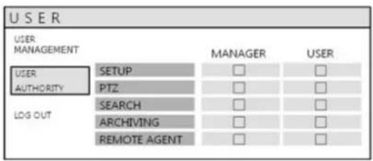
User can give authority to the MANAGER and USER accounts by putting check marks next to the desired fields.
Be sure to click the APPLY button after selecting each item.
Please note: Any user can be deleted except the default ADMIN user.
USER : LOG OUT
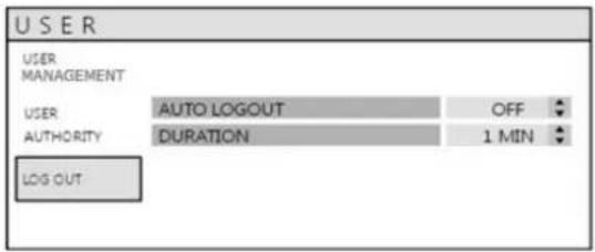
AUTO LOGOUT : This setting turns the feature on and off. AUTO LOGOUT ON/OFF. When set to ON, the DVR will automatically log a user out.
DURATION : When AUTO LOGOUT is set to ON, this feature determines the length of time before the system automatically logs a user out.
SYSTEM SETUP
NETWORK
Click the NETWORK menu to access the DVR's network settings.
NETWORK : IP SETUP
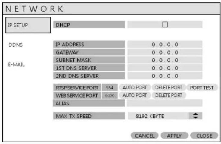
Click the IP SETUP menu.
DHCP : When enabled, the DVR will obtain an IP address automatically if it is connected to a DHCP server or router.
IP ADDRESS : If DHCP is not being used, the IP address can be manually set.
GATEWAY : If DHCP is not being used, the gateway IP address can be manually set.
SUBNET MASK : If DHCP is not being used, the subnet mask can be manually set.
1ST DNS SERVER : If DHCP is not being used, the first DNS server can be manually set.
2ND DNS SERVER : If DHCP is not being used, the second DNS server can be manually set.
RTSP SERVICE PORT : If the connected Router supports UPnP (Universal plug and play) function,
when you click the AUTO PORT, the port forwarding is automatically setup.
Clicking DELETE PORT will delete the port, and PORT TEST will test the ports.
WEB SERVER PORT : If the connected Router supports UPNP (Universal plug and play), clicking AUTO PORT will automatically complete the port forwarding. Clicking DELETE PORT will delete the port, and PORT TEST will test the ports. The Web Server Port is also the port number that the DVR uses to support remote connection from Internet Explorer or other web browsers.
ALIAS : When you enter the DDNS HOST NAME in DDNS setup, you can see the information here (only when connected to a UPNP router.
MAX TX SPEED : Specifies the maximum bandwidth that the DVR can use during a remote connection.
HOW TO OBTAIN AN IP ADDRESS
One of the easiest ways to obtain an IP address for your DVR is to use the built-in DHCP feature of your DVR.
HOW TO SET UP DHCP
The purpose of DHCP is to obtain all of the network information from the connected router. In most cases, the best way to do this is to cycle the DHCP feature, or in other words, turn it on, then off again. This will get the network information from the router, and then by turning DHCP off in the DVR, it will lock that address to the DVR.
Using the DHCP Feature:
1) Go to your DVR's 'main' menu, →System Setup→Network
2) 'IP SETUP' should be selected by default. To the right, 'DHCP' is listed. If it is 'checked', uncheck it, then select 'Apply' at the bottom of the screen. You should get a pop-up indicating the network is rebooting.(If DHCP was unchecked, see below)
3) Once the network reboots, go back and 'check' DHCP and select Apply. Again, the network will reboot.
4) Make note of your DVR's IP address; you will need this for port forwarding.
5) Now, go back and 'unchecked' DHCP; this will set your DVR's IP address to STATIC
If DHCP is ‘unchecked’, select it, then select ‘Apply’ at the bottom of the screen. You should get a pop-up indicating the network is rebooting. Make note of your DVR’s IP address; you will need this for port forwarding.
Now, go back and 'unchecked' DHCP; this will set your DVR's IP address to STATIC.
SYSTEM SETUP
NETWORK : DDNS
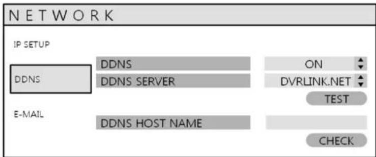
DDNS : When enabled, the DVR can be accessed through a Dynamic DNS server. Commonly used if a broadband connection does not have a static IP address.
CAUTION
To use the DDNS function, ports 8080 and 554 must be opened. (This is commonly known as port forwarding).
a. Default WEB SERVER PORT: 8080
b. Default RTSP SERVICE PORT: 554
Default DDNS HOST NAME is set to the MAC (Media Access Control) address.
Creating your DDNS Host Name
The EHL series allows you to actually name your DVR, and access it by that name.
Steps
1) Access the DVR's main menu by using the remote control, or by the buttons on the front of the unit
2) The Setup box will appear. Select "System Setup"
3) Select "Network"
4) Select "DDNS"
5) Make sure DDNS is turned "ON"
1) Make sure DDNS is turned ON
2) Highlight HOST NAME and press enter. The virtual keyboard will appear. Change the Host Name to your desired name by removing the previous entry--you can do this by repeatedly selecting the key. (When choosing your host name, please don't include any spaces or special characters). Once you have entered your desired host name, select OK.
4) Select "CHECK" under DDNS Registration to make sure the name is available.
5) Select "TEST" under DDNS Connection to make sure you have a connection to the server
6) Select APPLY at the bottom of the screen to apply your changes
7) Bring up a browser (ex. Internet Explorer), and type: http://your-ddns-hostname.dvrlink.net:8080 in the address bar.
For example: If your DDNS Host Name was Johndoesdvr, you would type: http://johndoesdvr.dvrlink.net:8080
NOTE: If you changed the webport, you will need to use that number, NOT 8080.
SYSTEM SETUP
REMOTE ACCESS
You can remotely access your VT-EH series DVR in the following ways:
- The DVR's MAC address
- The DVR's DDNS Host Name (by default this is set to the MAC address)
- Your external static IP address (if you have one)
\*\*\*\*\*IMPORTANT\*\*\*\*\*
In order to view your DVR remotely you must port forward BOTH the Web Server Port (the default is 8080) and the RTSP Service Port (the default is 554). If you need assistance with port forwarding, please reference your router's manual or contact your Network Administrator/IT Professional.
1. MAC Address
The MAC address is a unique identifier assigned to your DVR. By default, this address is listed as the DDNS Host Name.
Here is how to find your DVR's MAC address:
- Access the DVR's main menu by using the remote control, or by using the buttons on the front of the unit.
- The Setup box will appear. Select "System Setup."
- Select "System."
- Select "System Management."
- Select "System Information."
- The MAC address will be displayed here.
- Bring up a browser (ex. Internet Explorer), and type:
http://the-mac-address-of-your-dvr.dvrlink.net:8080 in the
address bar. For example, if your MAC address was
001155555555, you would type:
http://001155555555.dvrlink.net:8080.
| SYSTEM INFORMATION | |
| F/W VERSION | FIRM WARE Ver. |
| H/W VERSION | HARDWARE ID |
| VIDEO SIGNAL TYPE | NTSC |
| DISK CAPACITY | 244 GB |
| IP ADDRESS | 192.168.1.1 |
| MAC ADDRESS | 000000000000 |
| DDNS DOMAIN NAME | DVRLINK.NET |
| RTSP SERVICE PORT | 554 |
| WEB SERVER PORT | 8080 |

NOTE: If you changed the webport, you will need to use that number, NOT 8080.
SYSTEM SETUP
REMOTE ACCESS
2. DDNS Host Name
The EHL series allows you to name your DVR, and access it by that name.
Steps to name your DVR
- Access the DVR's main menu by using the remote control, or by using the buttons on the front of the unit.
- The Setup box will appear. Select "System Setup."
- Select "Network."
- Select "DDNS."
- Make sure DDNS is turned "ON."
- "DDNS Host Name" – this is your host name. To create a new host name, please see page 35
- Bring up a browser (ex. Internet Explorer), and type: http://your-ddns-hostname.dvrlink.net:8080 in the address bar.
For example, if your DDNS Host Name was Johndoesdvr, you would type: http://johndoesdvr.dvrlink.net:8080.

NOTE: If you changed the webport, you will need to use that number, NOT 8080.
SYSTEM SETUP
3. IP Address
If you have a STATIC IP ADDRESS, you can use this to access your DVR.
Accessing the DVR REMOTELY
To access the DVR remotely via IP address, use the WAN IP address of the network the DVR is connected to. (Sometimes this IP address is referred to as the LIVE, PUBLIC or OUTSIDE IP address)
Steps:
- Bring up a browser (ex. Internet Explorer), and type: http://your.static.ip.address:8080 in the address bar.
For example, if your STATIC IP address was 10.10.10.10, you would type: http://10.10.10.10:8080
NOTE: if you changed the webport, you will need to use that number, NOT 8080.
If you are on the same network as the DVR you will need to use the DVR's IP address to access it.
Steps:
- Access the DVR's main menu by using the remote control, or by using the buttons on the front of the unit.
- The Setup box will appear. Select "System Setup."
- Select "Network."
- "IP SETUP" should be selected by default. To the right, you should see the DVR's IP address.
- Bring up a browser (ex. Internet Explorer), and type: http://your.DVR's.ip.address:8080 in the address bar.
For example, if your DVR's IP address was 192.168.0.2, you would type: http://192.168.0.2:8080
NOTE: if you changed the webport, you will need to use that number, NOT 8080.
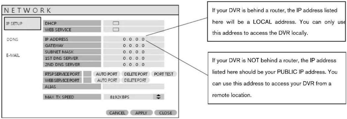
NETWORK : E-MAIL
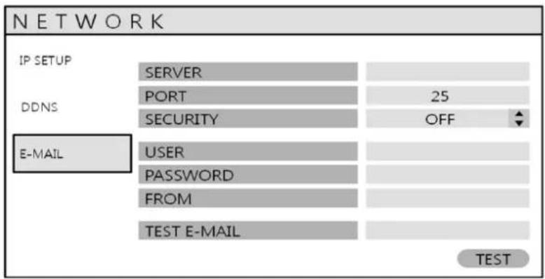
Click the E-MAIL menu.
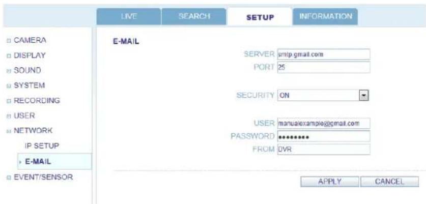
SERVER : The SMTP outbound email server that should be used to send email notifications.
PORT : The outbound email port number.
SECURITY : Set to OFF if the SERVER does not require a username and password to connect.
USER : Enter a username to identify the DVR in email messages.
PASSWORD : If SECURITY is set to ON, enter the password here.
FROM : Input an e-mail address or any text. It is only used for the e-mail test (e-mail sender)
TEST E-MAIL : Enter an e-mail address to send test e-mails to.
*Please contact your ISP, Email Provider, and/or Network Administrator if help is needed obtaining your email information.
SYSTEM SETUP
EVENT / SENSOR
Click the EVENT / SENSOR menu.
To setup the various event handling options, highlight EVENT/SENSOR and press ENTER.
EVENT / SENSOR : HDD EVENT
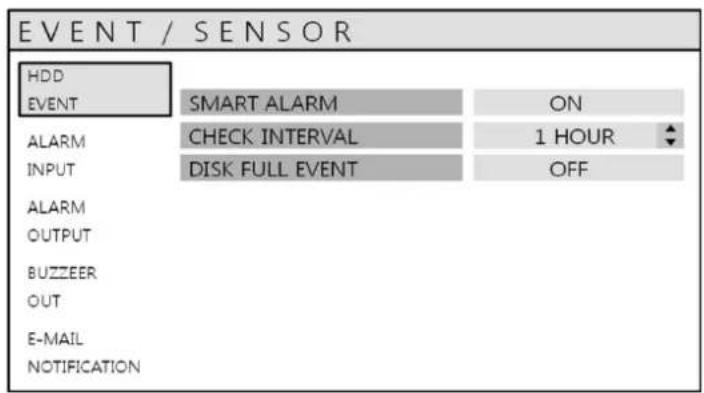
Click the HDD EVENT menu.
The DVR can monitor the hard drives and detect problems that may be developing.
SMART ALARM : Enables SMART disk monitoring. S.M.A.R.T. (Self-Monitoring, Analysis and Reporting Technology) is a monitoring system to detect and report on various indicators of hard drive reliability, in the hope of anticipating failures.
CHECK INTERVAL : Can be adjusted as desired.
DISK FULL EVENT : Determines ON/OFF.
EVENT / SENSOR : ALARM INPUT
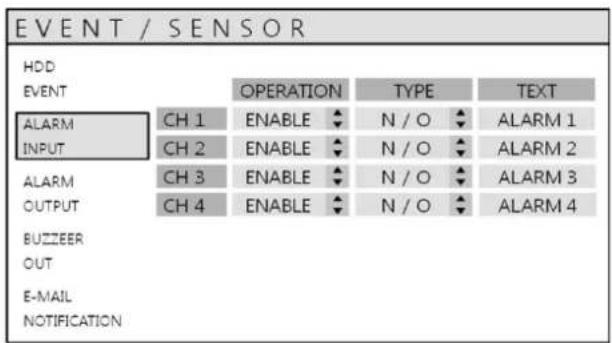
Click the ALARM INPUT menu and click the OPERATION and TYPE values.
Determine the behavior of each of the 4 alarm inputs.
OPERATION : Alarm inputs can be enabled or disabled.
TYPE : Alarm inputs can be set as normally open or closed.
TEXT: The text can be changed for each alarm input.
SYSTEM SETUP
EVENT / SENSOR : ALARM OUTPUT
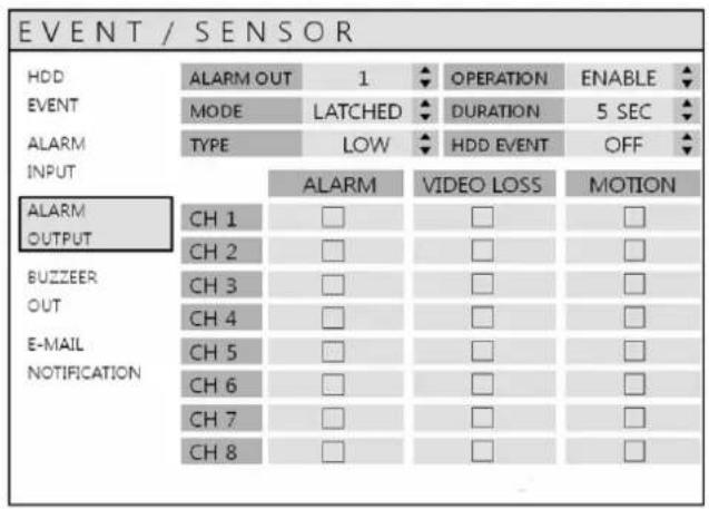
Click the ALARM OUTPUT menu and click each value.
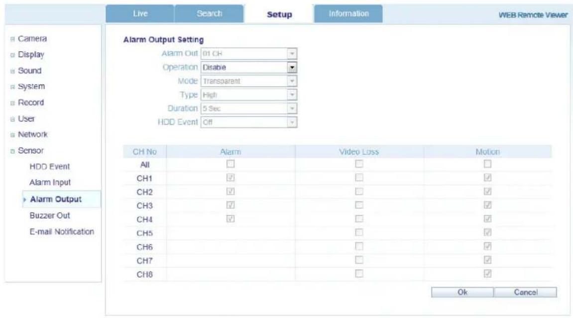
Determine the behavior and actions that will trigger each of the 1 alarm output.
Behavior settings
ALARM OUT : Choose which alarm output to configure.
OPERATION : The selected alarm output can be enabled or disabled.
MODE : Can be either TRANSPARENT (the output is active only when the trigger criteria is present) or LATCHED (the output is active for a set period of time after a trigger).
DURATION : In LATCHED mode, the time that the alarm output remains active after it has been triggered.
TYPE : Can be set to HIGH (0V to +5V when activated) or LOW (+5V to 0V when activated).
HDD EVENT : Determines whether a hard drive event triggers the alarm output.
Action settings
ALARM EVENT : Determines whether alarm inputs will trigger the alarm output.
VIDEO LOSS : Determines whether video loss on any of the selected channels will trigger the alarm output.
MOTION : Determines whether motion detection on any of the selected channels will trigger the alarm output.
Remember to select APPLY and press ENTER to save all settings before exiting these menus
SYSTEM SETUP
EVENT / SENSOR : BUZZER OUT
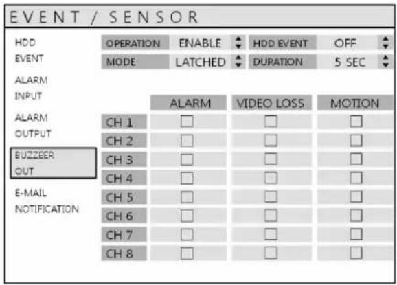
Determine the behavior and actions that will trigger the internal buzzer.
Behavior settings
OPERATION : The internal buzzer can be enabled or disabled.
HDD EVENT : Determines whether a hard drive event sounds the buzzer.
MODE : Can be either TRANSPARENT (the buzzer sounds only when the trigger criteria is present) or LATCHED (the buzzer sounds for a set period of time after the trigger).
DURATION : In LATCHED mode, the time that the buzzer sounds after it has been triggered.
Action settings
ALARM EVENT : Determines whether alarm inputs will sound the buzzer.
VIDEO LOSS : Determines whether video loss on any of the selected channels will sound the buzzer.
MOTION : Determines whether motion detection on any of the selected channels will sound the buzzer.
Remember to select APPLY and press ENTER to save all settings before exiting these menus
SYSTEM SETUP
EVENT / SENSOR : EMAIL NOTIFICATION
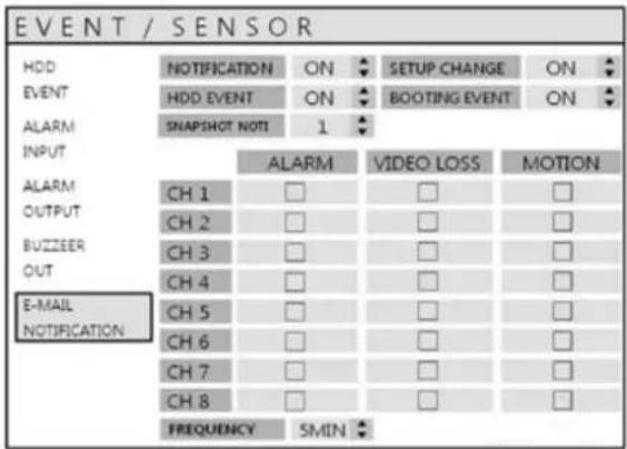
Determine the behavior and actions that will send an email to a remote user.
Behavior settings
NOTIFICATION : Email notification can be turned ON or OFF.
SETUP CHANGE : Determines whether a setup change sends an email.
HDD EVENT : Determines whether a hard drive event sends an email.
BOOTING EVENT : Determines whether a booting event sends an email.
SNAPSHOT NOTIFICATION : Determines whether an image(JPEG) of the selected channel sends an email.
Action settings
ALARM EVENT : Determines whether alarm inputs will send an email.
VIDEO LOSS : Determines whether video loss on any of the selected channels will send an email.
MOTION : Determines whether motion detection on any of the selected channels will send an email.
FREQUENCY : E-mail sending period (Max. 60 MIN)
Email settings must also be configured in MAIL and USER MANAGEMENT from USER MANAGEMENT menu.
SYSTEM SETUP
DISK MANAGE
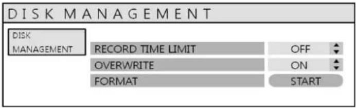
Click the DISK MANAGEMENT menu.
To manage the internal hard drives, highlight DISK MANAGE and press ENTER.
RECORD TIME LIMIT : In certain circumstances, it may be necessary to limit the amount of footage stored on the DVR (to comply with data protection laws for example).
Recording can be limited to 12 hour, 1 day, 2 day, 3 day, 4 day, 5 day, 6day, 1 week, 2 week, 3 week or one month. Once the DVR has this amount of footage stored, it will start to overwrite the earliest recorded footage.
OVERWRITE : When set to ON, the DVR will start overwriting the earliest recorded footage, once the hard drive becomes full. In this case, the percentage of hard drive used shown in live display will always be 99%. When it is set to OFF, the DVR will stop recording when the disk becomes full.
FORMAT : If necessary, all footage can be erased from the DVR using this option.
Please note: When a RECORD TIME LIMIT is set, the OVERWRITE option cannot be changed
RECORD MENU
RECORD MENU
Click the "MENU".
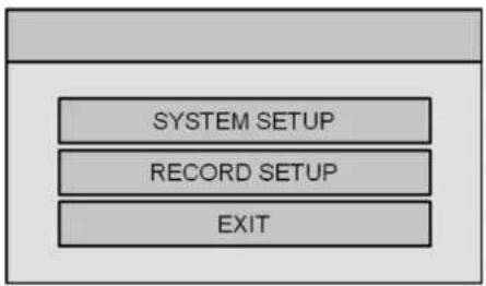
flowchart
graph TD
    A[" "] --> B["SYSTEM SETUP"]
    B --> C["RECORD SETUP"]
    C --> D["EXIT"]
Input the password. Then main menu will appear.
Click the RECORD menu.
To setup the recording behavior of the DVR, highlight RECORD MENU and press ENTER.
SCHEDULE MODE : DAILY (one schedule will apply to every day of the week) or
WEEKLY (each day of the week has its own schedule).
PRE EVENT RECORDING TIME : When the DVR is not in continuous recording mode, this setting determines the amount of time that is always recorded before an event occurs.
(motion detection, alarm input, etc).
POST EVENT RECORDING TIME : When the DVR is not in continuous recording mode, this setting determines the amount of time that is always recorded after an event occurs.
(motion detection, alarm input, etc).
NETWORK STREAMING MODE : Determine the quality of network streaming.
AUTO : System determines the quality based on network bandwidth.
MANUAL : System transmits the data as defined in Network Streaming (see page 51).
OFF : System transmits the data as standard recording stream (see page 48).
RECORD MENU
RECORD : CONTINUOUS/MOTION
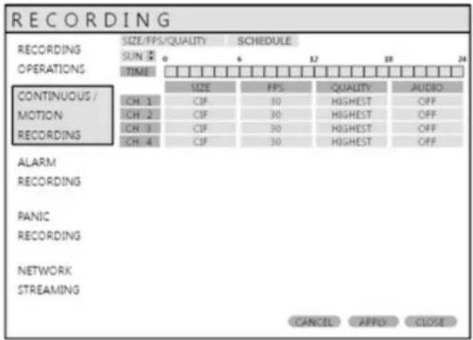
Click the CONTINUOUS/MOTION SETUP menu.
This setup screen allows the operator to configure scheduled and motion detection recording.
There are 2 sections:
SIZE/FPS/QUALITY : Recording settings for each channel can be defined across a 24 hour period,
in blocks (for example between 09:00 and 18:00) or for each individual hour.
Note that when SCHEDULE MODE is set to WEEKLY, each day of the week can also be selected.
SCHEDULE : This section determines at what times the DVR will record and whether it is in continuous recording or motion detection.
SIZE/FPS/QUALITY
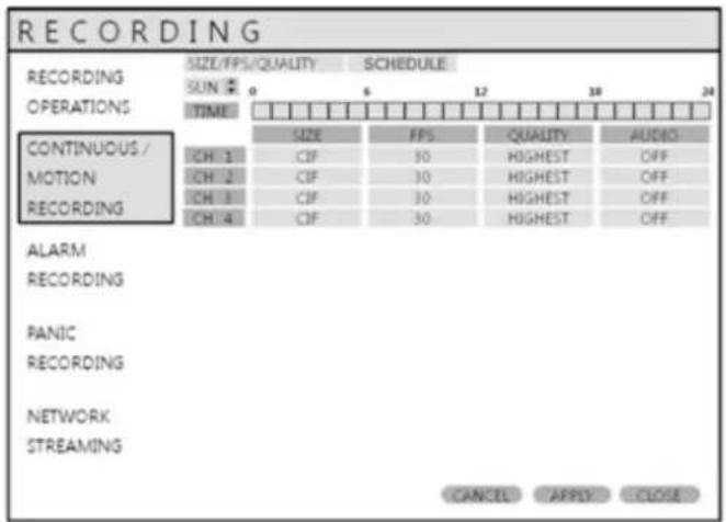
Click the SIZE/FPS/QUALITY menu.
To change the SIZE/FPS/QUALITY, highlight CONTINUOUS/MOTION RECORDING and press ENTER.
Ensure the SIZE/FPS/QUALITY is highlighted and press ENTER again.
RECORD MENU
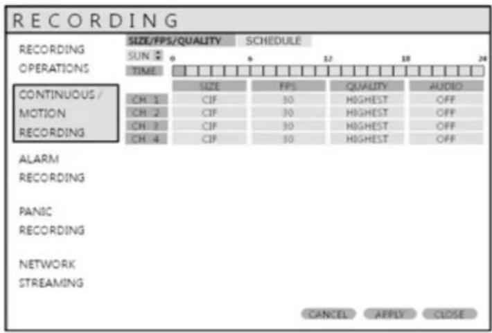
If using a mouse :
Click the TIME BAR and "drag" the time the user wants to have the values changed. After dragging, release the mouse button; then see pg 49.
Press ENTER two times, move the green cursor to the desired start time. Press enter again, them then select the desired time period by moving the green box. This can be done with the control keys on the DVR or on the remote control. Once the desired time has been selected, press ENTER one time to bring up the SIZE/FPS/QUALITY window (see page 48)
The table below shows time selection set at 09:00 and 18:00
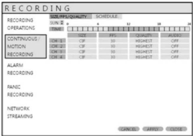
Example: To change the recording settings between 09:00 and 18:00.
Use the CURSOR KEYS to move the green cursor to the 09:00 position and press ENTER.
Use the CURSOR KEYS to stretch the green cursor across to the 18:00 position, then press ENTER
RECORD MENU
SIZE / FPS / QUALITY
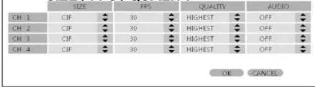
To change the values of the SIZE, FPS, QUALITY and AUDIO, highlight the desired field, then click to adjust the values.
If using the remote or front panel buttons, highlight the desired field, press enter, then use the directional UP or DOWN buttons to adjust the values.
Once all desired changes have been made, select OK.
The Recording settings for the selected time period are displayed.
The maximum recording frame rate is 60FPS at resolution of D1.
SIZE : Recording resolutions of 352x240, 704x240 or 704x480(NTSC) can be selected for each channel.
FPS : Frame rates between 1 and 25 or 30 can be set for each channel.
QUALITY : Four different picture recording qualities can be set for each channel.
AUDIO : If audio devices are connected to the DVR, user can select the audio recording on/off.
Any audio channel can be assigned to any of the video channels. Please refer to camera setup menu on page 18.
During playback, when a particular channel is selected in full screen, the assigned audio channel will be played back at the same time.
Adjust values as desired and select OK to finish and return to the parameter menu.
Other time periods can be configured in the same manner.
Remember that if SCHEDULE MODE is set to WEEKLY, recording settings need to be changed for each day as well as for each particular time.
Note: The DVR supports a maximum recording rate across all channels of 60 frames per second at 704x480/576 resolution. As settings are adjusted, the 'frames available' at bottom left displays the number of available frames still remaining and must always be zero or higher.
If, while changing recording settings, this figure becomes negative, recording resolutions and / or frame rates must be lowered to increase the 'frames available' value to zero or above.
RECORD MENU
SCHEDULE
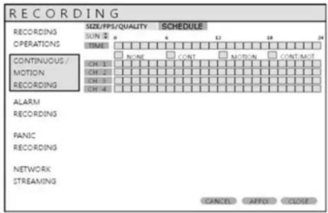
Click the SCHEDULE menu.
To change SCHEDULE settings, highlight CONTINUOUS/MOTION RECORDING and press ENTER.
Use the CURSOR KEYS to highlight SCHEDULE and press ENTER.
The schedule box is highlighted.
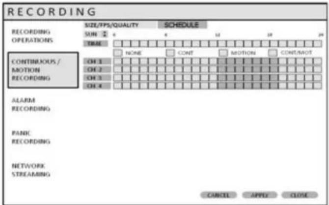
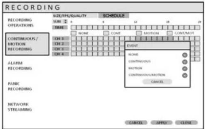
To change the record schedule, highlight the desired channel(s) in relation to the TIME bar (similar to SIZE/FPS/QUALITY setup on page 47). After selecting the area, determine the recording type: NONE, CONTINUOUS, MOTION, CONTINUOUS MOTION.
The schedule screen has 4 symbols to show the different recording modes.
NO COLOR blocks: No scheduled or motion recording.
SKY BLUE blocks: The DVR will record continuously.
BLUE block: The DVR will only record while motion is detected.
ORANGE block: The DVR will record continuously and with motion event.
RECORD MENU
RECORD : ALARM SETUP
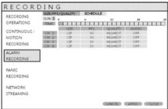

Click the ALARM RECORDING menu.
The setup is the same as CONTINUOUS/MOTION RECORDING
This setup screen allows the operator to configure alarm input activated recording.
SIZE/FPS/QUALITY : Recording settings for each channel can be defined across a 24 hour period,
in blocks (for example between 09:00 and 18:00) or for each individual hour.
Note that when SCHEDULE MODE is set to WEEKLY, each day of the week can also be selected.
SCHEDULE : This section determines at what times the DVR will monitor the alarm inputs and activate recording.
Please refer to Continuous / Motion setup on setting up SIZE/FPS/QUALITY and ACTIVATION.
Alarm activated recording can be used in conjunction with Continuous / motion recording.
For example, the DVR could be configured to record continuously at a low frame rate (set in Continuous / Motion Recording) and then increase to a higher frame rate during an alarm input (set in alarm setup).
RECORD MENU
RECORD : PANIC SETUP
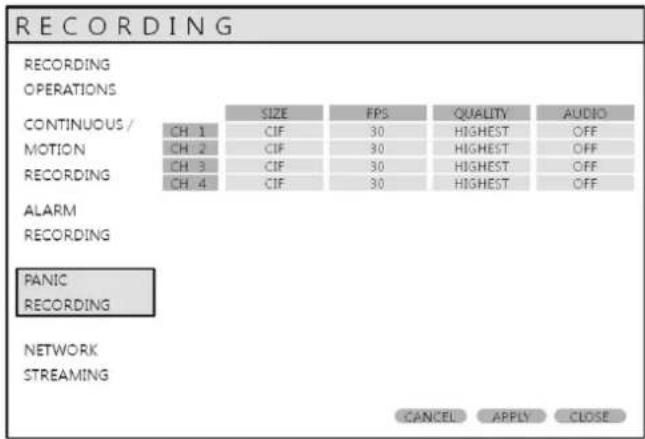
Select the PANIC RECORDING menu.
To change the values of the SIZE, FPS, QUALITY and AUDIO, highlight the desired field, then click to adjust the values.
During panic recording mode, the DVR will override all other recording settings and record continuously on all channels at the settings configured here.
RECORD : NETWORK STREAMING SETUP
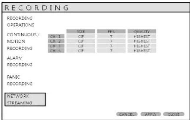
Select the NETWORK STREAMING menu.
To change the values of the SIZE, FPS, QUALITY and AUDIO, highlight the desired field, then click to adjust the values.
When the Network Streaming mode is set to MANUAL (see page 45), the uploaded video, and audio stream can be customized for desired network performance.
Maximum recording frame rate is 30FPS at resolution of 1CIF (352x240).
SEARCH
SEARCH
To search for a particular section of recorded footage, press the SEARCH button.
To protect unauthorized viewing of footage, permission levels can be set for MANAGER and USER accounts (see page 33).
To login as ADMIN, enter the default password of 1234 and press ENTER.
SEARCH : TIME SEARCH
![SEARCH 00 02 04 06 08 10 12 14 16 18 20 22 BY TIME SEARCH BY EVENT 2009 APRIL S M T W T F S 1 2 3 4 5 6 7 8 9 10 11 12 13 14 [15] 16 17 18 19 20 21 22 23 24 26 26 27 28 29 30 CH.1 CH.2 CH.3 CH.4 17:35:07 PLAY CLOSE](/content/2026/06/1182103/images/7155e555ef3daaaa09d15cf1b7109187ec582e52705c7be46d388428e54f75d0.jpg)
Select SEARCH B Y TIME
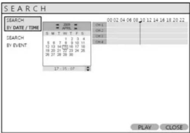
Click the desired date.
The DVR uses a calendar and timeline search method for quick access to recorded footage.
The calendar displayed on the left shows the current month.
Days highlighted have recorded footage.
The timeline on the right shows a 24 hour status of all channels for the selected day.
The recorded time will be displayed with different color on each recording type.
Panic : White
Motion : Green
Continuous : Sky blue
Alarm : Red
SEARCH
USING A MOUSE :
Drag the time bar with left mouse click to select the desired time, then click PLAY
USING THE REMOTE/DVR
Press ENTER to select the calendar and use the CURSOR KEYS to move to the desired day.
As different days are selected, the timeline display also changes to show recorded footage on that day.
Press ENTER to choose the day and move to the timeline.
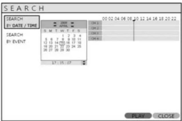
Use the CURSOR KEYS to move the timeline cursor left or right to select the time segment required.
The currently selected time is displayed under the calendar.
Press PLAY to begin playback from the selected time.
SEARCH
SEARCH MODE : Multi Playback
| CH1 | CH2 |
| CH3 | CH4 |
 | |

PLAY (Multi view):
The default playback mode is 4 screen displays.
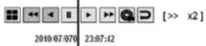
By pressing DISPLAY or using the CHANNEL SELECTION buttons, it is possible to display single screen or other multi screen formats in a similar way to the live display mode.
When playback is paused, the <<, >> can be used to accurately move the footage forward or backwards, frame by frame.
Playback speed and direction can also be controlled using the five playback buttons.
SEARCH
During playback, the user can reserve recorded data that needs to be archived.
Select the button at the time the archive is to be started (or press the ARCHIVE button on the remote) Playback is then stopped and menu below will appear.
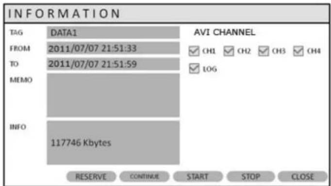
After inputting "TAG" name, press START. Then display is returned to playback.
Press 📷 button again to end archiving. Then menu below will appear again.
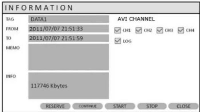
STOP : Ends the current playback, and allows user to RESERVE the data.
RESERVE : Press this to reserve current data.
CONTINUE : Press this to reserve more data. Then display will return to playback.
START : Press this to start the reserve.
CLOSE : Finish archiving.
Reserved data will be reserved on HDD. User can see the reserved data from "RESERVED DATA MANAGEMENT" on ARCHIVING menu
SEARCH
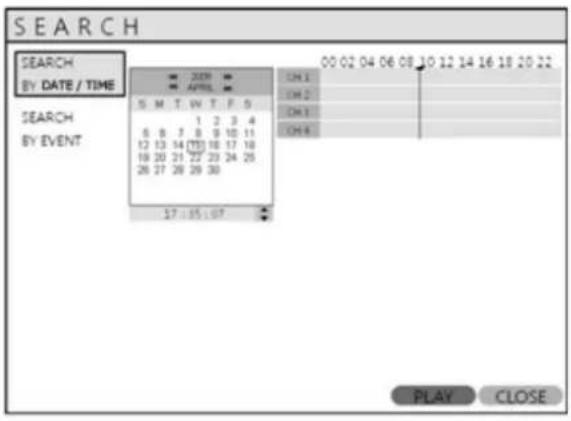
To exit playback mode and return to the search screen to choose another time and date, press RETURN.
To exit the search screen and go back to live view, repeatedly press RETURN.
SEARCH : EVENT SEARCH
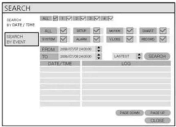
The DVR event log stores events such as motion and alarm activated recording, video loss, etc.
To search for an event and playback the recorded footage, press the SEARCH button and log in as ADMIN with the default password of 1234.
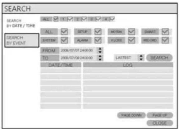
Click the SEARCH BY EVENT menu and select each desired channel and condition.
Change the time by using the ← button.
Click the SEARCH button.
SEARCH
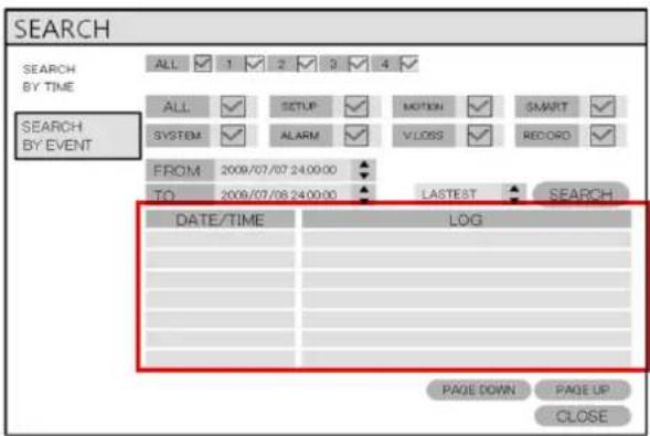
To playback footage for a particular event, select the event from the list using the CURSOR KEYS and press ENTER.
| CH1 | CH2 |
| CH3 | CH4 |
| [>> x2] |
Playback resumes from the moment the selected event occurred and continues until stopped by the operator.
During event search playback, the playback button can be used as normal.
To stop playback and return to live view mode, repeatedly press RETURN.
ARCHIVING
NEW ARCHIVING
To archive recorded footage to USB memory stick, insert memory stick into DVR, then press the ARCHIVE button.
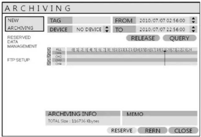
Click each desired channel(s)
Then select the FROM and TO values
Click the QUERY menu.
Make sure to press QUERY first before selecting BURN or RESERVE.
Press RELEASE to reset after QUERY.
RESERVE: Press this after inputting the TAG name.
OR
BURN : Press this after inputting the TAG name. Then press START after menu below appears.
Stop by pressing the STOP button on Burning.
![ARCHIVING NEW ARCHIVING TAG DEVICE RESERVED DATA MANAGEMENT FTP SETUP KXXXX ALL CH1 CH2 CH3 CH4 BURNING ATG NAME DATA3 DEVICE USB MEM BURNING TYPE BURNING WRITING... 55% SAVE CANCEL QUERY 9[20][21][22][23] ARCHIVING INFO MEMO TOTAL Size : 116736 Kbytes RESERVE RERN CLOSE](/content/2026/06/1182103/images/c5dbbf9304b38d2b1a9c9443ac743305001027e2292eb67408bcd096acda711d.jpg)
ARCHIVING
RESERVED DATA MANAGEMENT
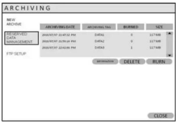
AVI ARCHIVING LIST : Lists all the reserved data.
INFORMATION : The detailed information of Reserved AVI data.
DELETE : User can delete the reserved AVI data
BURN : Backup the selected AVI data.
FTP SETUP
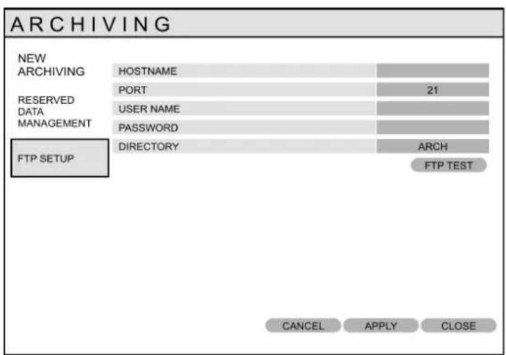
Archiving to an FTP site is possible, however the user must set up the Host Name, Port number, User Name, and Password with the FTP server.
FTP Archiving is available for both New Archiving and Reserved Data Management..
DIRECTORY – Archived data will be saved to this user-defined folder on your FTP site.
FTP TEST – tests connectivity to the FTP server.
WEB CONNECTION SETUP
PRELIMINARY BEFORE CONNECT
For connecting over the web (also known as Remote Viewing), ports 554 and 8080 need to be port forwarded in the router. Refer to the router's manual or contact the router's manufacturer for assistance with port forwarding.
| WEB RA MINIMUM PC REQUIREMENT | |
| CPU | P4 3.0 or Higher |
| RAM | 512MB or Higher |
| VGA | Geforce MS 400, Radeon 7500 or higher |
| Gefore 8 series or higher | |
| VGA MEMORY | 64MB |
| MONITOR | 1280X1024 |
| BROWSER | InternetExplorer, Firefox, Crome, Opera, Safari |
| IE VERSION | IE6.0 or higher |
| NETWORK | 100Mbps |
| DIRECT X | V7.0 or higher |
HOW TO CONNECT
Input the IP Address or URL of the DVR in the Internet Explorer Address Bar. See pages 34-38 for more details.

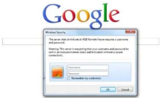
Default ID and password are 'ADMIN' & '1234'
*ID and password are case sensitive
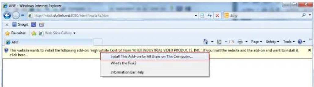
User needs to install Active-X, click Run Add-on
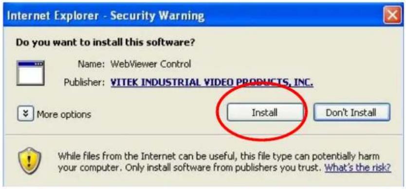
If there is a problem installing active-X, check the ActiveX option in IE security menu.
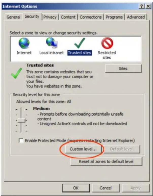
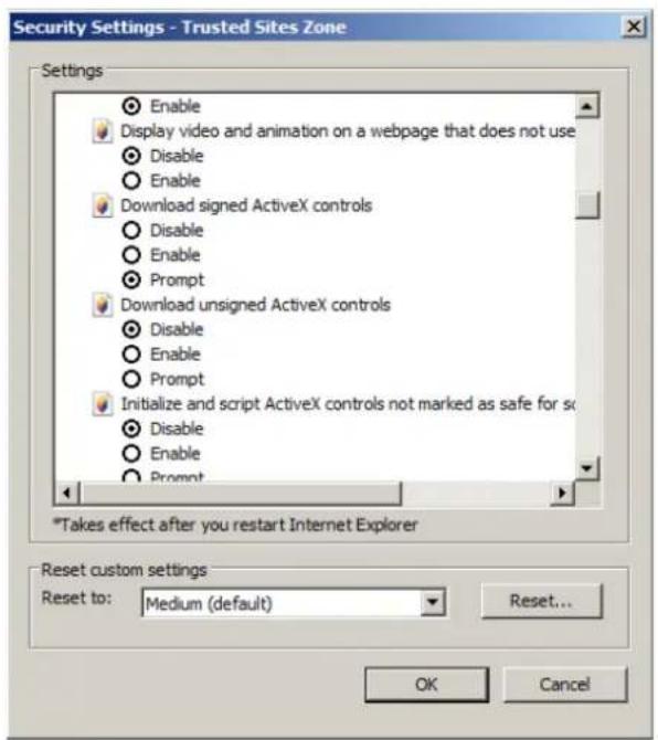
Select Enable for all ActiveX related options.
(Ex: Download signed ActiveX control, Download unsigned ActiveX control....)
LIVE MODE
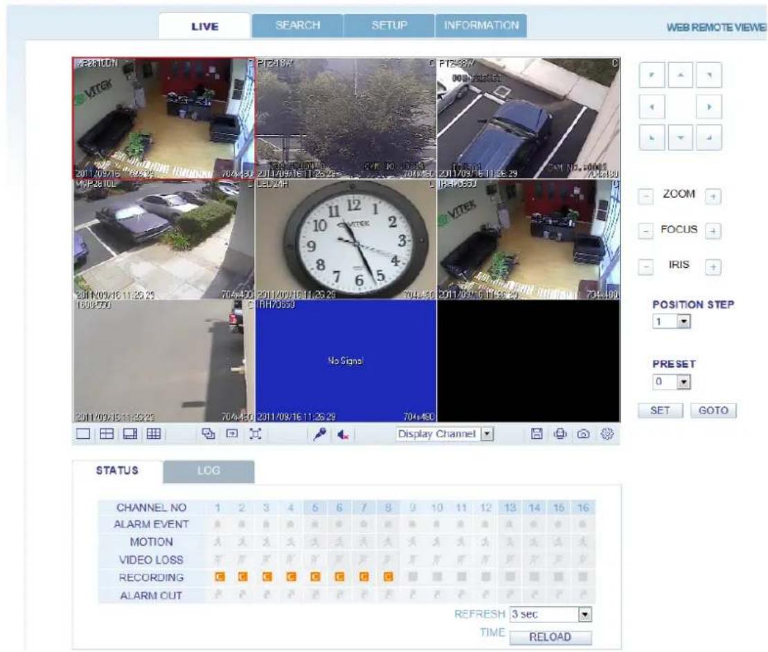
Features / functions in LIVE mode

Select live division screen (1, 4, 8, 9, 16 split mode)
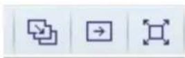
Sequence mode.
Move to next camera
Full screen.


Select live channel. – select a channel manually.
Activate Mic to send a sound to DVR.
On/Off Sound from DVR
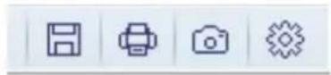
Save the live image.
Print the current screen.
Snapshot the current screen.
Setup (Render, Audio, Capture Type and Save Folder)
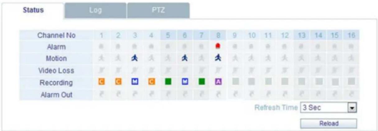
• Status: Show active status of DVR
- Alarm – Indicator will be marked when system detects Alarm input.
- Motion- Indicator will be marked when system detects Motion
- Video Loss - Indicator will be marked when system detects Video Loss.
- Recording – Display current recording mode

Continuous

Motion

Panic

Alarm

Stand By
- Alarm Out - Indicator will be marked when system detect Alarm output.
- Refresh Time – set interval of refresh or Reload for manual refresh.
- Log : Display all system logs with real time
| Status | Log | PTZ | |
| No | Camera Title | Date Time | Log |
| 1 | CH8 | 2011.06.26 21:34:16 | Motion Detection On: #8 |
| 2 | CH8 | 2011.06.26 21:34:16 | Motion Recording On : #8 |
| 3 | CH7 | 2011.06.26 21:34:16 | Motion Detection On: #7 |
| 4 | CH7 | 2011.06.26 21:34:16 | Motion Recording On : #7 |
| 5 | CH6 | 2011.06.26 21:34:16 | Motion Detection On: #6 |
| 6 | CH6 | 2011.06.26 21:34:16 | Motion Recording On : #6 |
| 7 | CH5 | 2011.06.26 21:34:16 | Motion Detection On: #5 |
| 8 | CH5 | 2011.06.26 21:34:16 | Motion Recording On : #5 |
| Page Down Page Up Refresh Time 3 Sec Reload | |||
• PTZ : Allows control of connected PTZ camera(s).
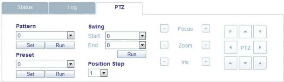
- Pattern – move a camera among several preset position
- Preset – set a position of camera view.
- Swing - move a camera between two preset points.
SEARCH (By time line)
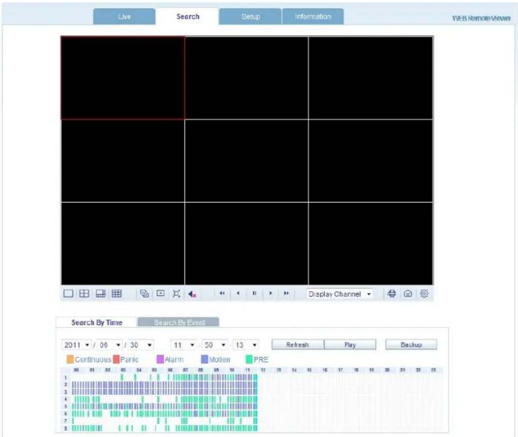
- Select a time line on time table or set an exact time.
- Then press 'Play' button
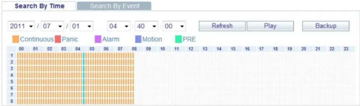
- Refresh: Refresh the recording table of data.
- Play: Start to display the recorded data from system.
- Backup: User can archive the recorded data to a remote site (PC).
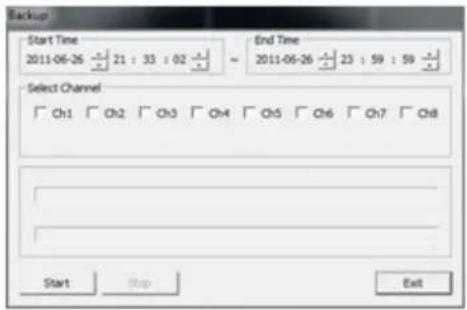
Backup (Archive)
- Select the desired Start and End Time
- Select the desired channel(s)
- Click Start. By default, the video will be saved to: C:\SaveFolder
SEARCH (By Event)
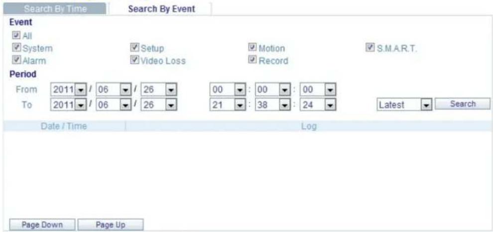
- Event: Select events for querying.
- Period: Set duration for querying recording data.
- Search: Start to query and display all events on the list.
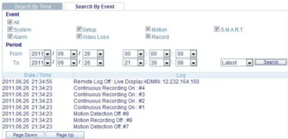
- Clicking on an event will start the playback of that event.
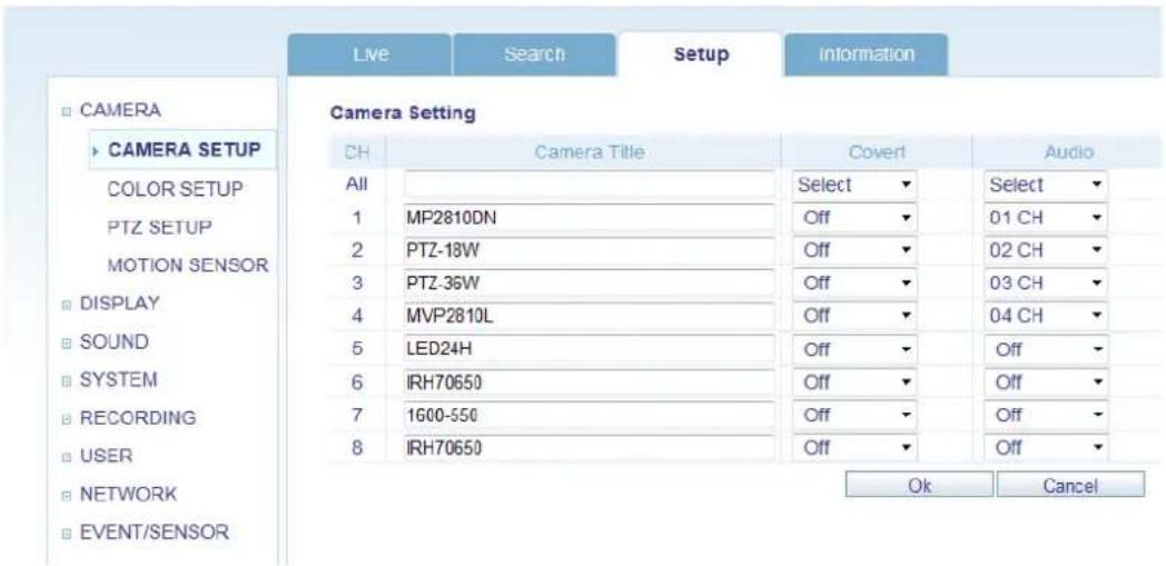
1. CAMERA
User can configure camera's attributes such as title, live color, PTZ setup or motion.
● Motion setup for detecting motion events.
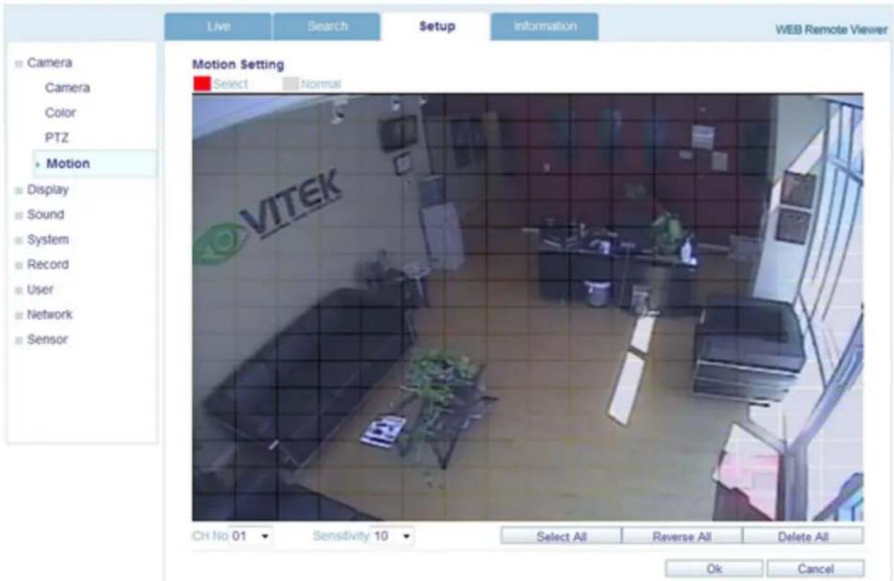
1) Select Motion menu tab.
2) Select a channel and sensitivity.
3) Drag a mouse on the image to select detecting area.
4) Press OK.
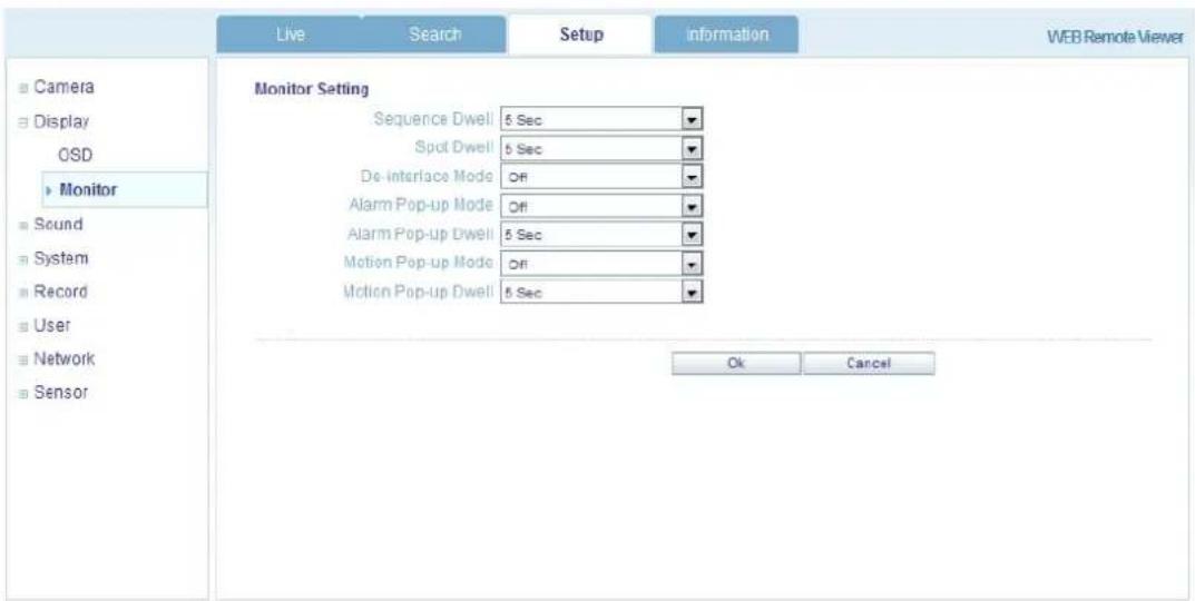
2. Display
1) OSD – Choose text to display over the image.

2) Monitor - User can set dwell time for sequence or spot, and pop up function.
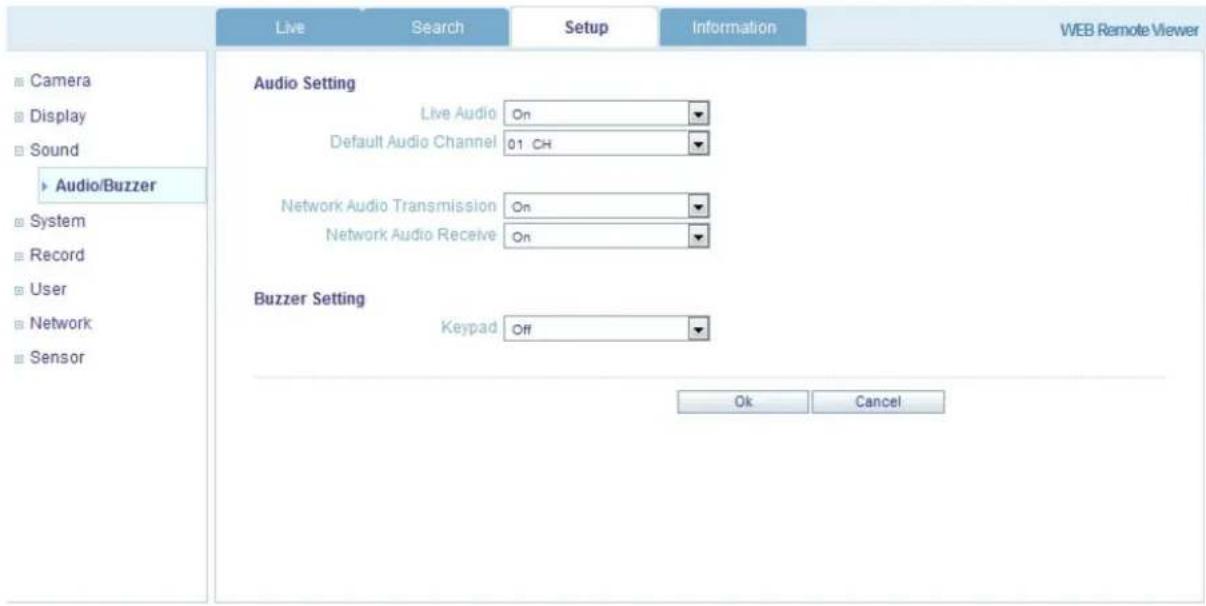
3. Sound
1) Audio Setting – Select a live audio channel and activation
2) Buzzer setting – Activate buzzer out for event notification
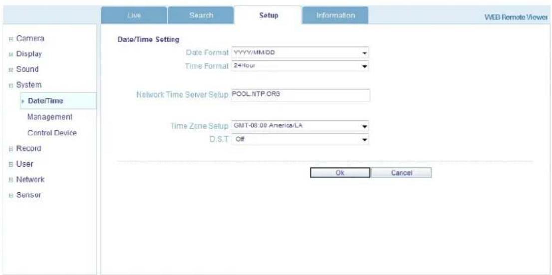
4. System
User can configure the system date, check system information and set controller.
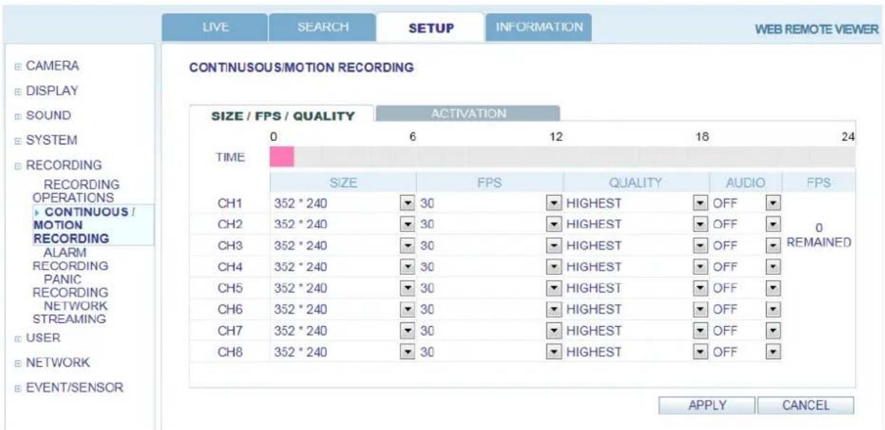
5. Recording
User can configure the recording parameters.
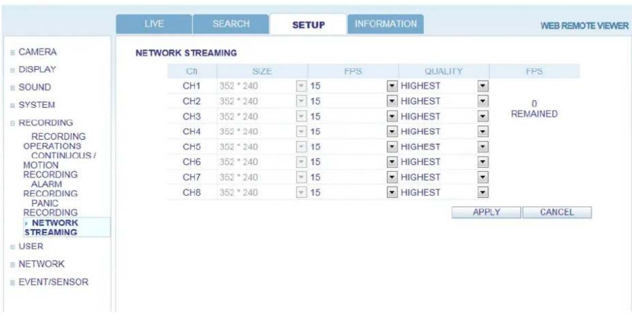
6. Network Streaming
This feature allows user to adjust frame rate (FPS) and quality of video that is transmitted over the network.
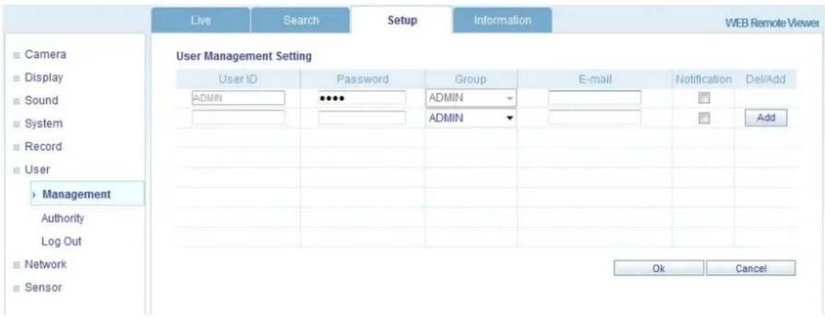
7. User
To add a User, select Add, then assign Authority level and Log Out time.
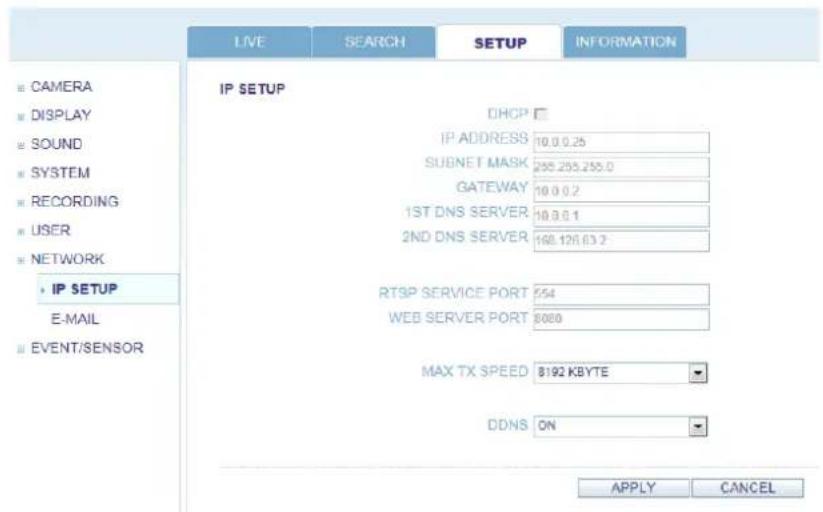
8. Network
User can check the system's network information and selectable speed level.
IP settings are not allowed to be changed on the remote site. The Network IP can only be changed from the DVR.
For email notification, enter the SMTP server details.
9. Sensor
Set sensor options for Alarm in/out, Buzzer out for event notification.
(HDD EVENT, Alarm Input, Alarm output, Buzzer out, E-mail notification option)
All detail setup follow DVR system setup
INFORMATION
Display Model name of DVR and WEB Remote Software version.

flowchart
graph LR
    A["LIVE"] --> B["SEARCH"]
    B --> C["SETUP"]
    C --> D["INFORMATION"]
Web Viewer Information
DVR Model: 08CH / 240FPS
WEB Version : WEB_v1.77_1.2.2.7_110518
BACKUP PLAYER
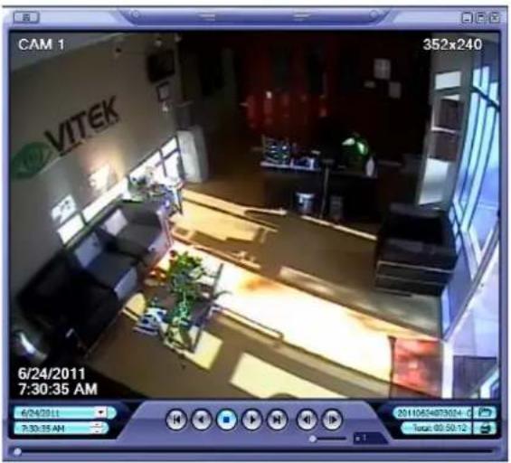
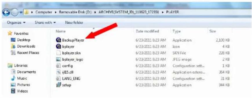
To view archives backed up from a DVR, double click BackupPlayer (located in the Player folder). NOTE: When archiving from the web browser to a PC, the BackupPlayer is NOT included. To obtain the BackupPlayer, user must physically archive from the DVR to a USB flash drive.
Click to choose which archive file to playback.
Playback of the archive file begins.
The controls under the display can be used to adjust playback direction and speed.
WATERMARK PROCESS
- Run "BackupPlayer" then select the desired archived media.
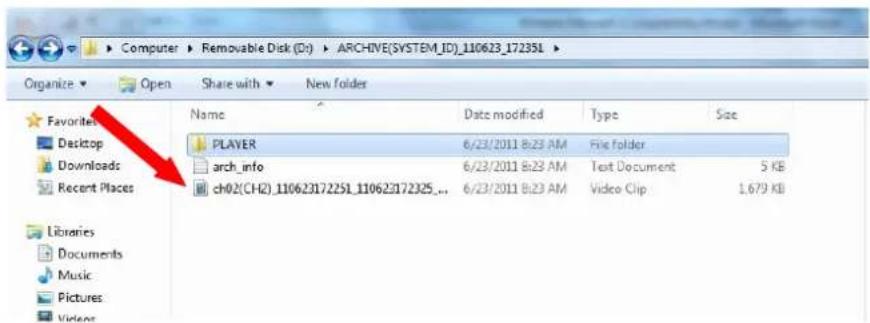
VT-EHL Series
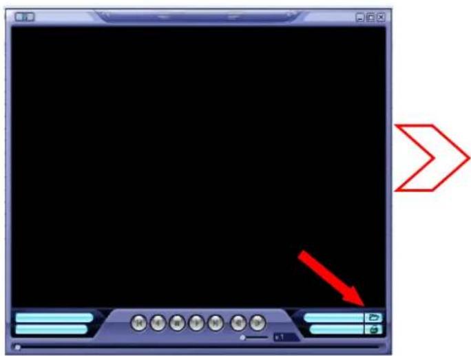
- Click the [Open file] button and open the backup file.
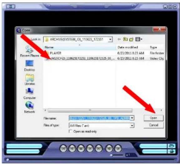
- After opening file, select "Yes" to check the watermark.
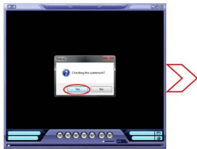
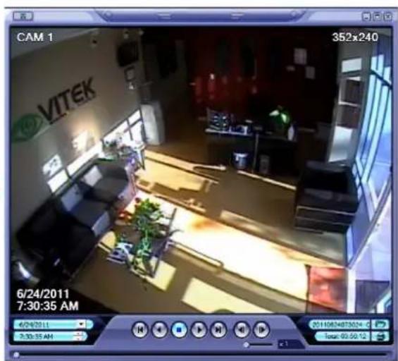
- If the backuped AVI file is modified, [Verification failed] message will be appeared.
SMARTPHONE CONNECTION
iPhone
- Select the Safari browser.
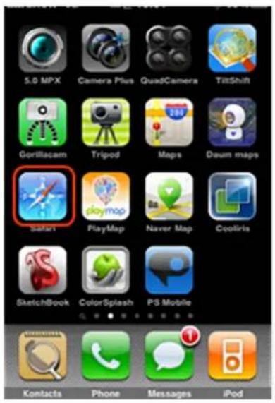
- Enter the IP address or URL to connect. And Click the [GO] button.
![vitek.dvrlink.net:8080 1 2 3 4 5 6 7 8 9 0 @ & % ? , = [ ] #+= _ : - + ABC . / .com Go](/content/2026/06/1182103/images/739f4b1c9c38649a1303791f5526f177cf709cd153bd5651cfde0b85089bbd75.jpg)
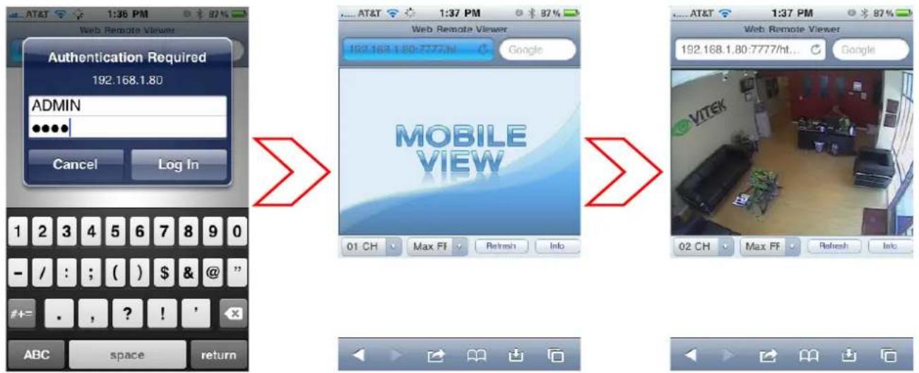
- Enter the User name and Password then use can see the Image.
(Default: ADMIN / 1234)
BlackBerry
-
Select the Web browser.
-
Enter the IP address or URL to connect.
And press the Enter button.
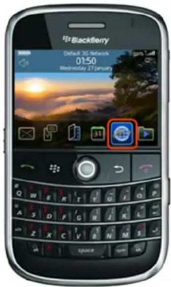
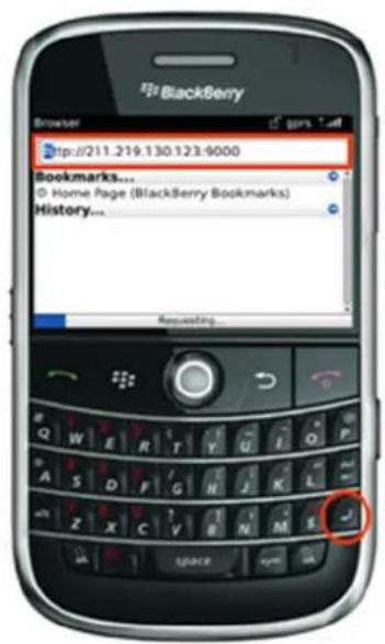
- Enter the User name and Password then use can see the Image.
(Default: ADMIN / 1234)
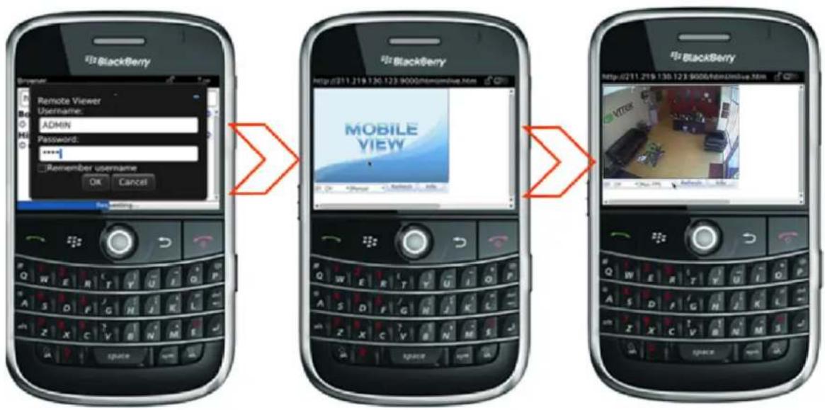
'DVR Viewer' Guide (iPhone / iPad / Android)
1.1 – Install & Connect (iPhone & iPad)
- Search and Install "Vitek DVR Viewer" in Apple APPstore
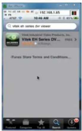
- Run 'DVR Viewer' Application
- ADD Connection List

- Server Name
This is just a way to differentiate between multiple DVR's in the list. Please name your DVR anything you like, then Save.
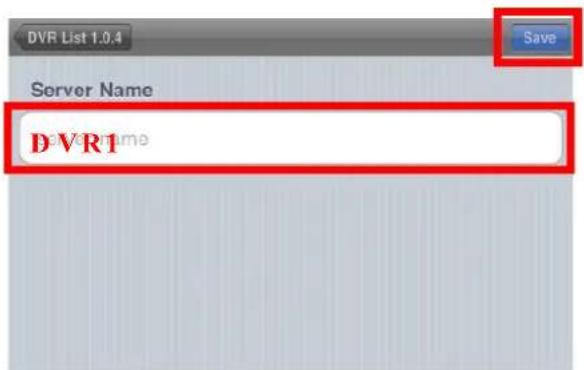
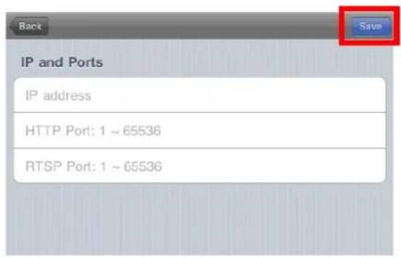
5. Insert IP and ports then save
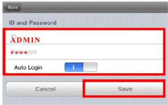
6. Insert ID, Password and login type select (Default: Auto Login) then save
7. Select DVR in list

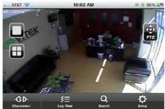
8. View CAMERA live video
1.2 – Install & Connect (Android)
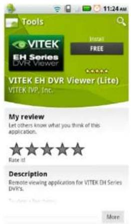
- Search and Install "Vitek EH DVR Viewer" in Android market
- Run 'Vitek EH DVR Viewer' Application

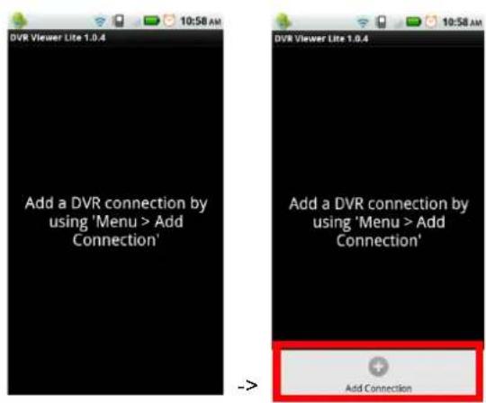
- ADD Connection List (Select menu button)
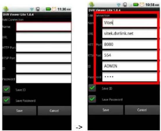
- Insert name, URL, ports, ID, Password and select ID/Password save type then select 'Save' button
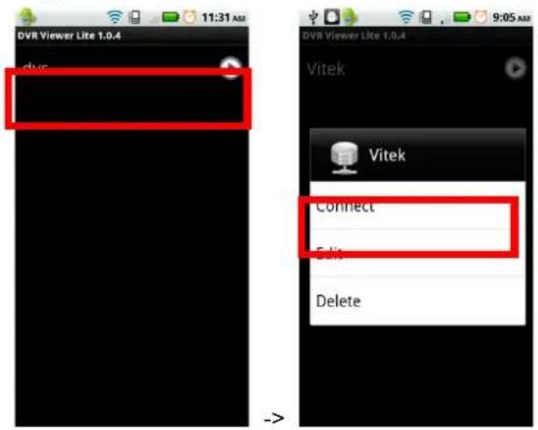
- Long press DVR in list then select Connect button
2 - PTZ & Snapshot (PRO version)
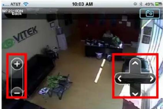
- Touch the 'PTZ' button
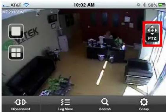
- Set PTZ by pressing '+/-/∧/∨/</>' button.
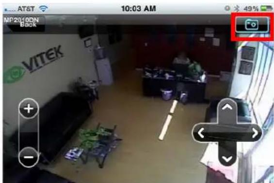
- Set Image Capture By using 'camera' Button.
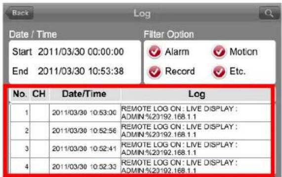
3 - Log View (PRO version)
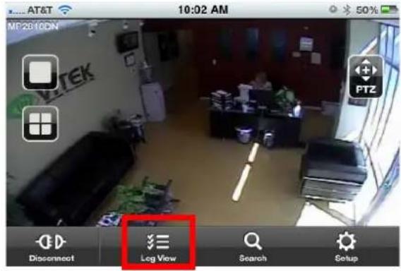
- Touch the 'log view' button
VT-EHL Series
2. Select start/end time and Filter Option select after touch 'search' button
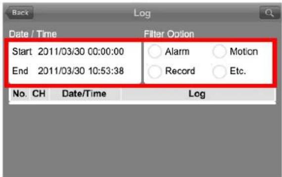
3. View the log list
4 - Search (PRO version)
1. Touch the 'Search' button
-
Select date/time and touch play button
-
User can do the playback, rewind, Fast-forward and Split Screen Search.
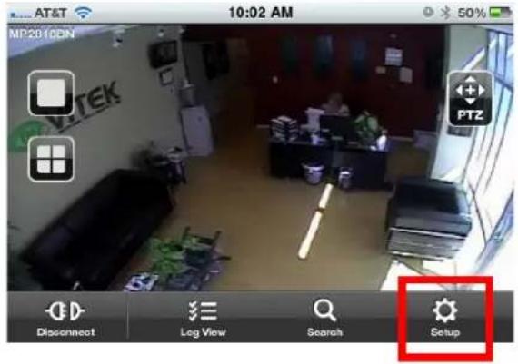
5 - Setup (PRO version)
- Touch the 'Setup' button
VT-EHL Series
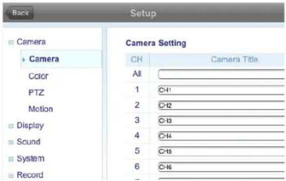
- The Setup menu includes the same settings as the DVR.
EH CONNECT - MAC COMPATIBILITY
Users can connect to the DVR with a Mac computer.
Steps
1. Click the Add icon
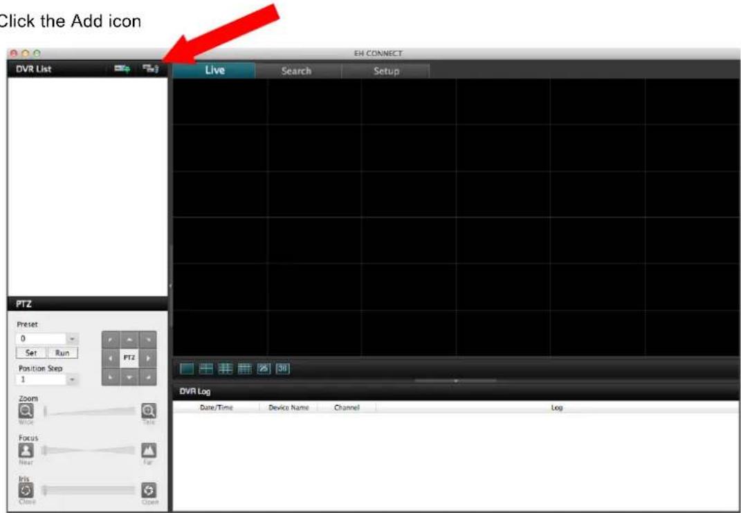
2. Click on "Devices", then click "+" to add a device. Once you have added your device, click "OK".
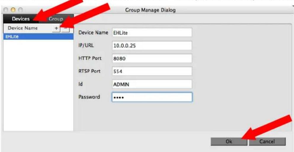
VT-EHL Series
3. Click the Add icon again
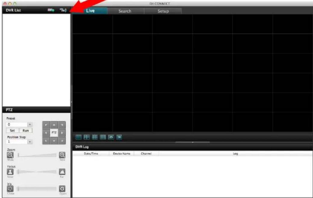
4. Click "Group"
a. Click the "+" to add a new Group.
b. Give the new group a name next to "Group Name"
c. Select "OK"
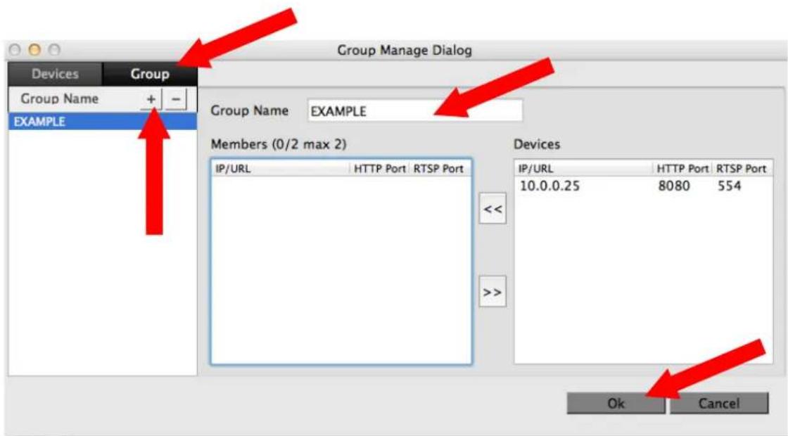
5. Click Add icon again
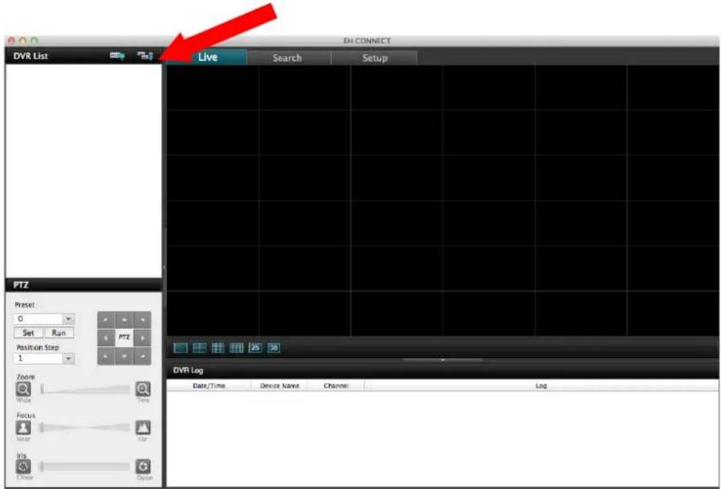
6. Click "Group"
a. Click on a device in the "Devices" section
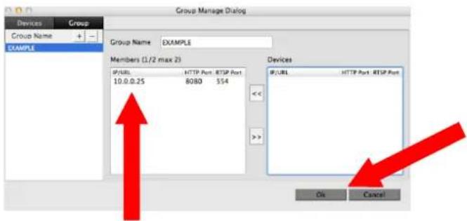
b. Click the “<<” button to move the device from the Devices list to the Members of the Group on the left. (See Fig A)
c. Your device should now be located under Members. (See Fig. B). Now click "OK" Fig. A
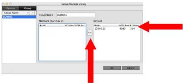
Fig. B
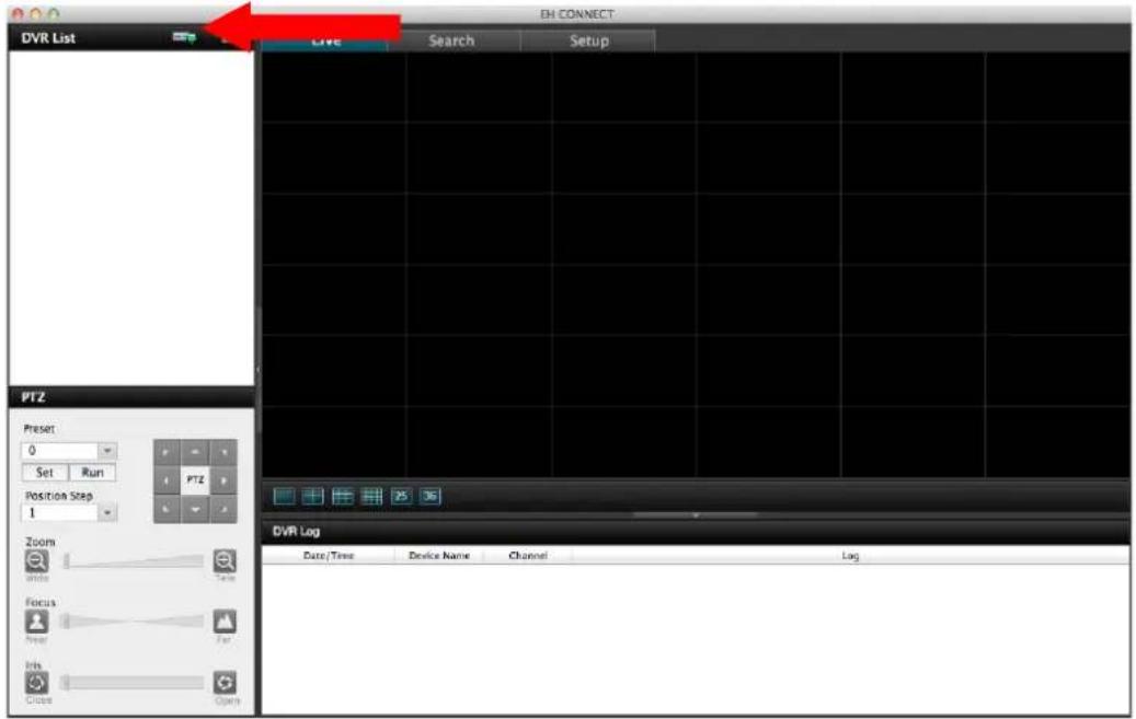
7. Click the "Connect" button
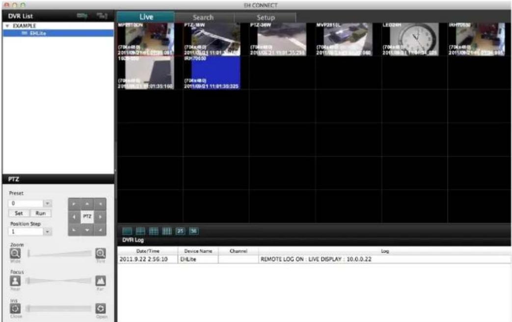
8. Your DVR should now be connected.
ALPHA DOME CAMERA SERIES
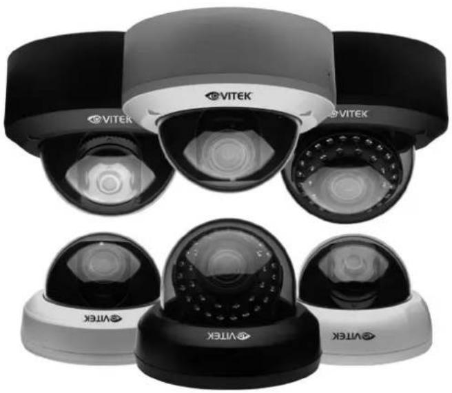
A 620TVL Multi Purpose Wide Dynamic Color Dome Camera with a 3 Year Warranty at a price that will shock even the savviest consumer.
The New VITEK Hercules Digital Processor provides features and performance found only in cameras more than twice the cost. Built in Wide Dynamic Range for challenging lighting demands, 3D Digital Noise Reduction, Digital Slow Shutter, Motion Detection and Privacy Function are just a start.
The All New Alpha Series Dome Camera Lineup comes equipped with OSD, Secondary Video Output and 3-Axis Positioning and is available in fixed, 2.8-12mm Varifocal, Infrared and Vandal/Weather Resistant versions making this camera an Ultra Versatile choice.
natural_image
Exterior view of multiple VITEK security cameras with black and white dome structures (no visible text or symbols)
natural_image
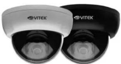
Two VITEK-branded headsets with black and white covers, no visible text or symbols on the product body.VTD-A4F/I
Indoor High Resolution WDR Dome Camera with 3.6mm Fixed Lens
natural_image
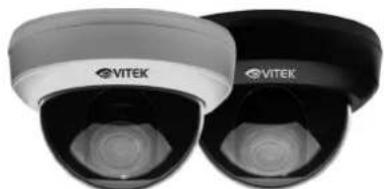
Two VITEK-branded security camera units with black and white casing (no visible text or symbols)VTD-A2812/I
Indoor High Resolution WDR Dome Camera with 2.8\~12mm IR Corrected Auto-Iris Lens
natural_image
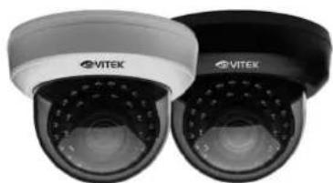
Two VITEK security cameras shown from different angles (no text or symbols visible)VTD-AR2812/I
Indoor High Resolution 35 LED Infrared WDR Dome Camera with 2.8\~12mm IR Corrected Auto-Iris Lens
natural_image
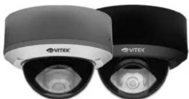
Two VITEK-branded security camera units shown from different angles (no visible text or symbols on the devices themselves)VTD-A4F/V
IP68 Rated Vandal Resistant High Resolution WDR Dome Camera with 3.6mm Fixed Lens
natural_image
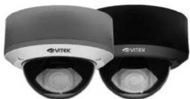
Two VITEK-branded security camera units with black and gray casing (no visible text or symbols)VTD-A2812/V
IP68 Rated Vandal Resistant High Resolution WDR Dome Camera with 2.8\~12mm IR Corrected Auto-Iris Lens
natural_image
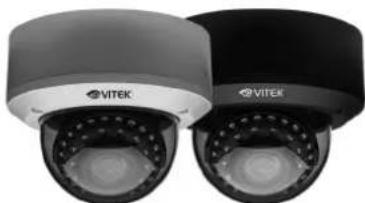
Two VITEK security cameras shown from different angles (no text or symbols visible)VTD-AR2812/V
IP68 Rated Vandal Resistant High Resolution 35 LED Infrared WDR Dome Camera with 2.8\~12mm IR Corrected Auto-Iris Lens
VISIT WWW.VITEKCCTV.COM FOR COMPLETE INFORMATION!
VITEK LIMITED PRODUCT WARRANTY
VITEK products carry a three (3) year limited warranty. Digital recording and storage products are also warranted for 3 years except for the hard drives which carry their own independent five (5) year factory warranty from the hard drive manufacturer. VITEK warrants to the purchaser that products manufactured by VITEK are free of any rightful claim of infringement or the like, and when used in the manner intended, will be free of defects in materials and workmanship for a period of three (3) years, or as otherwise stated above, from the date of purchase by the end user. This warranty is nontransferable and extends only to the original buyer or end user customer of a Vitek Authorized Reseller.
"Alpha Series by VITEK" products carry a three (3) year limited warranty. All other factors of the standard VITEK warranty will apply as stated above. ** Three Year "Alpha Series by VITEK" Warranty effective September 1st 2010. "Alpha Series by VITEK" products purchased prior to September 1st 2010 carry a one (1) year warranty.
** Three Year Warranty on all products except Alpha Series became effective on April 1st 2009. Legacy Products purchased prior to April 1st 2009 carry a two (2) year warranty.
This warranty shall not apply to repairs or replacements necessitated by any cause beyond the control of VITEK, including but not limited to, acts of nature, improper installation, excess moisture, misuse, lack of proper maintenance, accident, voltage fluctuations, or any unauthorized tampering, repairs or modifications. This warranty becomes VOID in the event of alteration, defacement, or removal of serial numbers.
Within the first 6 months of purchase, VITEK will replace or credit any defective product at the request of the customer (subject to availability) with a new product that equals or exceeds the performance of the original product purchased.
Within the first 6 months of purchase, at its sole discretion, VITEK may issue an advance replacement for a defective product; however, all related costs including, but not limited to shipping and/or delivery charges will be the responsibility of the customer. If upon return inspection a product is determined to be in good working order or shows evidence of misuse, the customer will be responsible for full payment of the original product purchased as well as the replacement product.
Beyond the first 6 month period for the remainder of the warranty, VITEK'S responsibility shall be limited to repairing the defective product, including all necessary parts and related labor costs. At its sole discretion, VITEK may choose to either exchange a defective product or issue a merchandise credit towards future product purchases. Any replacement parts furnished in connection with this warranty shall be warranted for a period not to exceed the remaining balance of the original equipment warranty.
A Return Authorization number or "RA" number must be obtained prior to the return of any item for repair, replacement, or credit. VITEK requires that this "RA" number be clearly printed on the outside of the shipping carton to avoid refusal of said shipment. The Return Authorization number expires after 30 days. Products returned after the 30 day period will be subject to refusal. Shipping charges, if any, must be prepaid. A copy of the bill of sale (or invoice of purchase), together with a complete written explanation of the problem must accompany all returns.
Vitek makes no warranty or guarantee whatsoever with respect to products sold or purchased through unauthorized sales channels. Warranty support is available only if product is purchased through a Vitek Authorized Reseller.
DISCONTINUED/REGRADE POLICY
Recently discontinued – 20% off If the product is not on our current price list but IS on our previously published price list (outside of 6 months) we can offer 20% off of the customers price level.
Warranty is VITEK's standard limited 3 year on recently discontinued products.
Discontinued over 6 months – 40% off If a product is not on our previous price list but is on the one before it (2 price lists ago – roughly one year) or older, we can offer 40% off of the customers price level.
Warranty on these products will be a limited one year only.
B-STOCK - 40% off B-Grade products are either refurbished or returned in "like-new" condition. They should always be working perfectly as specified and in excellent physical condition. B-Stock can be current or discontinued models.
Warranty on these products will be a limited one year only.
C-STOCK - 60% off C-Grade products are either refurbished or returned in "scratch & dent" condition. They should always be working perfectly as specified and in moderately good physical condition. C-Stock can be current or discontinued models.
Warranty on these products will be a limited six months only.
*Limited Warranty means that VITEK reserves the right to repair or replace any product found defective within the warranty time period, prorated to the date of original purchase. If VITEK cannot repair the product, VITEK reserves the right to replace it with an equal or better product and grade at VITEK's discretion.
- TABLE OF CONTENTS
- System Organization 10
- System Configuration 11
- Change the Main Monitor Out 14
- Connect and Power On 15
- Menu Control 16
- Live Display 16
- System Setup 20
- Display 25
- Sound 30
- System 31
- Record Menu
- Search
- Archiving
- Web Connection Setup
- VT-EHL Series
- Backup Player 76
- Smartphone Connection
- Mac Compatibility 88
- IMPORTANT SAFETY INSTRUCTIONS
- OVERVIEW
- CAUTION
- WARNING
- BEFORE INSTALLATION
- MAIN FEATURES
- MOUSE CONTROL
- ENHANCED GRAPHICAL USER INTERFACE [GUI]
- AUDIO
- BACKUP
- REMOTE CONNECTION
- COMPREHENSIVE RECORDING SETUP
- PTZ CONTROL
- TELEMETRY CONTROL
- EXTENSIVE MONITOR SUPPORT
- LIVE DISPLAY
- EMAIL SUPPORT
- SYSTEM ORGANIZATION
- Front panel description.
- Rear panel description.
- Remote Control
- Remote Control description.
- How to sync a remote controller to a DVR's ID
- Changing the Main Monitor Output
- CONNECT & POWER ON
- MENU CONTROL
- DIVISION SCREEN
- Sequence mode
- PTZ
- Digital Zoom
- Panic Recording
- SYSTEM SETUP
- SYSTEM SETUP MENU
- CAMERA
- CAMERA : PTZ SETUP
- DETAIL
- CAMERA : MOTION SENSOR
- DISPLAY
- DISPLAY - OSD
- DISPLAY : MONITOR
- DISPLAY : SEQUENCE
- DISPLAY : SPOT-OUT
- SOUND
- SOUND : AUDIO
- SOUND : BUZZER
- SYSTEM
- DATE / TIME
- SYSTEM : SYSTEM MANAGEMENT
- SYSTEM : CONTROL DEVICE
- USER
- USER : USER MANAGEMENT
- USER : USER AUTHORITY
- USER : LOG OUT
- NETWORK
- NETWORK : IP SETUP
- HOW TO OBTAIN AN IP ADDRESS
- HOW TO SET UP DHCP
- Using the DHCP Feature:
- NETWORK : DDNS
- Creating your DDNS Host Name
- Steps
- REMOTE ACCESS
- \*\*\*\*\*IMPORTANT\*\*\*\*\*
- MAC Address
- Here is how to find your DVR's MAC address:
- DDNS Host Name
- Steps to name your DVR
- IP Address
- Accessing the DVR REMOTELY
- Steps:
- NETWORK : E-MAIL
- EVENT / SENSOR
- EVENT / SENSOR : HDD EVENT
- EVENT / SENSOR : ALARM INPUT
- Behavior settings
- Action settings
- EVENT / SENSOR : BUZZER OUT
- EVENT / SENSOR : EMAIL NOTIFICATION
- DISK MANAGE
- If using a mouse :
- SCHEDULE
- RECORD : ALARM SETUP
- RECORD : PANIC SETUP
- RECORD : NETWORK STREAMING SETUP
- SEARCH : TIME SEARCH
- USING A MOUSE :
- USING THE REMOTE/DVR
- SEARCH MODE : Multi Playback
- PLAY (Multi view):
- SEARCH : EVENT SEARCH
- NEW ARCHIVING
- OR
- RESERVED DATA MANAGEMENT
- FTP SETUP
- PRELIMINARY BEFORE CONNECT
- HOW TO CONNECT
- LIVE MODE
- • Status: Show active status of DVR
- c c c c c c c c c c c c c c c c c c c c c c c c c c c c c c c c c c c c c c c c c c c c c c c c c c c c c c c c c c c c c c c c c c c c c c c c c c c c c c c c c c c
- - Log : Display all system logs with real time
- SEARCH (By time line)
- Backup (Archive)
- SEARCH (By Event)
- CAMERA
- Display
- Sound
- System
- Recording
- Network Streaming
- User
- Network
- Sensor
- INFORMATION
- Web Viewer Information
- BACKUP PLAYER
- WATERMARK PROCESS
- iPhone
- BlackBerry
- 'DVR Viewer' Guide (iPhone / iPad / Android)
- – Install & Connect (iPhone & iPad)
- Insert IP and ports then save
- Insert ID, Password and login type select (Default: Auto Login) then save
- Select DVR in list
- View CAMERA live video
- – Install & Connect (Android)
- - PTZ & Snapshot (PRO version)
- - Log View (PRO version)
- Select start/end time and Filter Option select after touch 'search' button
- View the log list
- - Search (PRO version)
- Touch the 'Search' button
- - Setup (PRO version)
- EH CONNECT - MAC COMPATIBILITY
- Click the Add icon
- Click on "Devices", then click "+" to add a device. Once you have added your device, click "OK".
- Click the Add icon again
- Click "Group"
- Click Add icon again
- Click "Group"
- Click the "Connect" button
- Your DVR should now be connected.
- ALPHA DOME CAMERA SERIES
- VITEK LIMITED PRODUCT WARRANTY
- DISCONTINUED/REGRADE POLICY
Brand : Vitek
Model : VT-EHL4
Category : Uncategorized