
AX-BM90122 - Media player Metra - Free user manual and instructions
Find the device manual for free AX-BM90122 Metra in PDF.

| Product Type | Media Player |
| Brand | Metra |
| Model | AX-BM90122 |
| Dimensions (approx.) | 10 x 10 x 2 cm |
| Weight (approx.) | 200 g |
| Power Supply | 5V DC via USB port |
| Playback Formats | MP3, WMA, WAV, JPEG, MPEG-4 |
| Display | 2.4-inch TFT screen |
| Memory Card Support | microSD up to 32GB |
| Audio Output | 3.5mm headphone jack, built-in speaker |
| Video Output | AV out (RCA) |
| USB Connectivity | USB 2.0 for data transfer and charging |
| Battery | Rechargeable Li-ion 800 mAh |
| Playback Time | Up to 5 hours |
| File Management | Folder navigation, playlists |
| Equalizer | Preset modes (Rock, Pop, Jazz, etc.) |
| Remote Control | Not included |
| Language Support | English, French, German, Spanish, etc. |
| Cleaning Instructions | Wipe with a soft, dry cloth. Do not use solvents. |
| Safety Warnings | Keep away from moisture and extreme temperatures. |
| Spare Parts Availability | Contact Metra customer service for parts. |
| Manual Download | Free PDF available at notice-facile.com |
Frequently Asked Questions - AX-BM90122 Metra
User questions about AX-BM90122 Metra
0 question about this device. Answer the ones you know or ask your own.
Ask a new question about this device
Download the instructions for your Media player in PDF format for free! Find your manual AX-BM90122 - Metra and take your electronic device back in hand. On this page are published all the documents necessary for the use of your device. AX-BM90122 by Metra.
USER MANUAL AX-BM90122 Metra
natural_image
Collection of various electronic components and connectors, including battery, charging cable, and audio jack (no visible text or labels)BMW (with M.O.S.T. 25 amplifier) 2004-2013
INTERFACE FEATURES
- Provides accessory power (12 volt 10 amp)
- Retains R.A.P. (retained accessory power)
- Designed for amplified models
- Retains audio controls on the steering wheel
- Retains phone buttons (radio dependent)
- Retains factory features: date, time, temperature display
- Micro-B USB updatable
INTERFACE COMPONENTS
- AX-BM90122 interface
- AX-BM90122 harness
- AX-BM90122 amplifier interface
- ASWC-1 harness
- ASWC-1 interface
- 3.5mm adapter
APPLICATIONS
BMW
1-Series 2004-2013 3-Series 2005-2012
TABLE OF CONTENTS
Connections 2
Installation 3
Programming 3
TOOLS & INSTALLATION ACCESSORIES REQUIRED
- Crimping tool and connectors, or solder gun, solder, and heat shrink • Tape • Wire cutter
- Zip ties
Product Info

CONNECTIONS
From the aftermarket radio to the AX-BM90122 harness, connect the:
- Black wire to the ground wire.
- Yellow wire to the battery wire.
- Yellow wire (6' long w/ fuse-holder) directly to the vehicles battery.
- Red wire to the accessory wire.
- Orange wire to the illumination wire (if applicable).
- Blue wire to the power antenna turn-on wire.
- Brown wire to the mute wire.
The following (3) wires are only for multimedia/navigation radios that require these wires.
- Blue/Pink wire to the VSS/speed sense wire.
- Green/Purple wire to the reverse wire.
• Light Green wire to the parking brake wire. - Tape off and disregard the following (8) wires, they will not be used in this application: Gray, Gray/Black, Green, Green/Black, Purple, Purple/Black, White, White/Black
- Red and White RCA jacks to the full range amplifier output jacks.
ASWC-1 harness:
This harness is only to be used if the vehicle is equipped with steering wheel controls.
- Connect the Black wire to the chassis ground.
- Connect the Red wire to accessory power.
-
For the radios listed below: Connect the 3.5mm adapter to the male 3.5mm SWC jack from the ASWC-1 harness. Any remaining wires tape off and disregard:
-
Eclipse: Connect the steering wheel control wire, normally Brown, to the Brown/White wire of the connector. Then connect the remaining steering wheel control wire, normally Brown/White, to the Brown wire of the connector.
- Metra OE: Connect the steering wheel control Key 1 wire (Gray) to the Brown wire.
- Kenwood or select JVC with a steering wheel control wire: Connect the Blue/Yellow wire to the Brown wire.
- XITE: Connect the steering wheel control SWC-2 wire from the radio to the Brown wire.
- Parrot Asteroid Smart or Tablet: Connect the 3.5mm jack into the AX-SWC-PARROT (sold separately), and then connect the 4-pin connector from the AX-SWC-PARROT into the radio.
Note: The radio must be updated to rev. 2.1.4 or higher software.
- Universal "2 or 3 wire" radio: Connect the steering wheel control wire, referred to as Key-A or SWC-1, to the Brown wire of the connector. Then connect the remaining steering wheel control wire, referred to as Key-B or SWC-2, to the Brown/White wire of the connector. If the radio comes with a third wire for ground, disregard this wire.
Note: After the interface has been programmed to the vehicle, refer to the manual provided with the radio for assigning the SWC buttons. Contact the radio manufacturer for more information.
- For all other radios: Connect the 3.5mm jack from the ASWC-1 harness, into the jack on the aftermarket radio designated for an external steering wheel control interface. Please refer to the aftermarket radios manual if in doubt as to where the 3.5mm jack goes to.
INSTALLATION
With the key in the off position:
- Connect the AX-BM90122 harness to the AX-BM90122 interface.
- Connect the AX-BM90122 harness to the AX-BM90122 amplifier interface.
- Remove the dust cover from fiber optic port in the AX-BM90122 amplifier interface.
- Connect the factory fiber optic cable into the AX-BM90122 amplifier interface.
- Connect the AX-BM90122 harness to the wiring harness in the vehicle.
- Connect the ASWC-1 harness to the ASWC-1 interface, and then to the AX-BM90122 interface.
PROGRAMMING
- Press and hold the Volume-Up button on the steering wheel.
- Turn the ignition on, the L.E.D. in the ASWC-1 interface will start flashing rapidly, which means the ASWC-1 is looking for the vehicle and the radio.
Note: If the L.E.D. did not start flashing rapidly, press the reset button for 3 seconds, while still holding the Volume-Up button.
• After a few seconds the L.E.D. should stop flashing rapidly, and then go out for approximately 2 seconds.
- After approximately 2 seconds there will be a series of 7 Green flashes, some short, and some long. The long flashes represent the wires that are connected to the ASWC-1. The 3rd, 4th, 5th, and 6th flashes should be longer.
Tip: Knowing this will help to troubleshoot, if need be.
- The L.E.D. will pause for another 2 seconds, and then flash Red up to 18 times depending on which radio is connected to the ASWC-1. Refer to the L.E.D. feedback section for information.
- This is the end of the auto detection stage. Release from holding the Volume-Up button. If the ASWC-1 detected the vehicle and the radio successfully, the L.E.D. will light up solid.
- Test the steering wheel controls for proper operation. Refer to the ASWC-1 instructions online at axxessinterfaces.com for customizing the buttons, if so desired.
PROGRAMMING (CONT.)
L.E.D. feedback
The (18) Red L.E.D. flashes represent which brand radio the ASWC-1 is connected to. Each flash represents a different radio manufacturer. For example, if you are installing a JVC radio, the ASWC-1 will flash Red (5) times, and then stop. Following is a legend that dictates which radio manufacturer corresponds to which flash.
L.E.D. feedback legend
| 1 flash - Eclipse (Type 1) † | 10 flashes - Clarion (Type 2) † |
| 2 flashes - Kenwood ‡ | 11 flashes - Metra OE |
| 3 flashes - Clarion (Type 1) † | 12 flashes - Eclipse (Type 2) † |
| 4 flashes - Sony / Dual | 13 flashes - LG |
| 5 flashes - JVC | 14 flashes - Parrot ** |
| 6 flashes - Pioneer / Jensen | 15 flashes - XITE |
| 7 flashes - Alpine * | 16 flashes - Philips |
| 8 flashes - Visteon | 17 flashes - TBD |
| 9 flashes - Valor | 18 flashes - JBL |
* Note: If the ASWC-1 flashes Red (7) times, and you do not have an Alpine radio connected to it, that means the ASWC-1 does not detect a radio connected it. Verify that the 3.5mm jack is connected to the correct steering wheel jack/wire in the radio.
** Note: The AX-SWC-PARROT is required (sold separately). Also, the Parrot radio must be updated to rev. 2.1.4 or higher through www.parrot.com.
^ Note: If you have a Clarion radio and the steering wheel controls do not work, change the radio type to the other Clarion radio type; same for Eclipse. Refer to the “Programming Information” document online
Note: If you have a Kenwood radio and the L.E.D. feedback comes back as showing as a JVC radio, change the radio type to a Kenwood. Refer to the "Programming Information" document online

AX-BM90122 INSTALLATION INSTRUCTIONS
Having difficulties? We're here to help.

our Tech Support line at:
386-257-1187

mail at:
techsupport@metra-autosound.com
Tech Support Hours (Eastern Standard Time)
Monday - Friday: 9:00 AM - 7:00 PM
Saturday: 10:00 AM - 7:00 PM
Sunday: 10:00 AM - 4:00 PM

KNOWLEDGE IS POWER
Enhance your installation and fabrication skills b enselling in the most recognized and respected
mobile electronics school in our industry.
Log onto www.installerinstitute.com or call
600-354-6782 for more information and take steps toward a better tomorrow.

Metra recommends MECP certified technicians
How to remove Fiber Optic cables from OE connectors
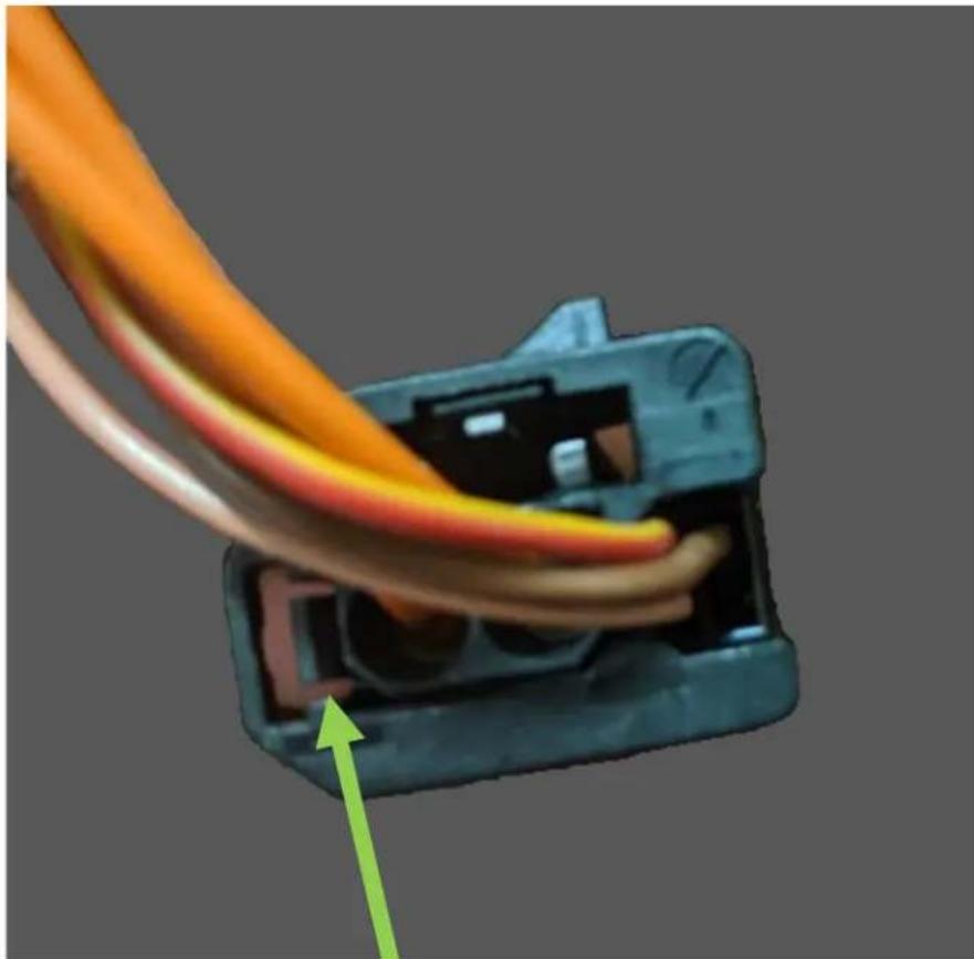
natural_image
Close-up of a black plastic electrical connector with orange and pink wires, showing internal wiring and a green arrow pointing to the connector (no text or symbols visible)Step 1.) Using a pick tool, carefully pull this tab towards the outside edge, then gently pull the fiber optic cable from the connector. (The fiber optic cables are in a plastic insert and will not come apart)
Step 2.) Remove the plastic insert from the fiber module (Fig a.), remove the gray dust cover (Fig b.), and insert the fiber cables, then plug the connector back in to the fiber decoder.
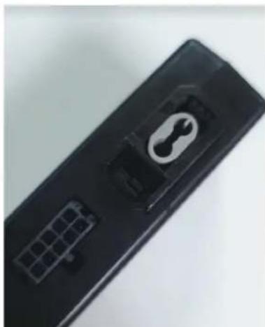
natural_image
Close-up of a black remote control device with a circular connector and grid pattern (no visible text or symbols)Figure A
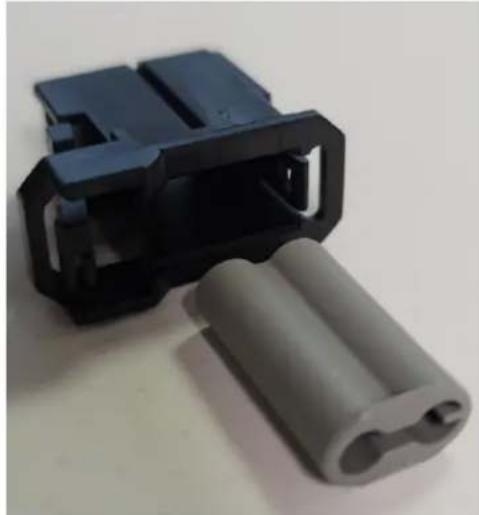
natural_image
Close-up of a blue plastic connector with a gray plastic housing, no visible text or symbols.Figure B
6/7/21
- BMW (with M.O.S.T. 25 amplifier) 2004-2013
- INTERFACE FEATURES
- INTERFACE COMPONENTS
- APPLICATIONS
- BMW
- TABLE OF CONTENTS
- TOOLS & INSTALLATION ACCESSORIES REQUIRED
- CONNECTIONS
- From the aftermarket radio to the AX-BM90122 harness, connect the:
- ASWC-1 harness:
- INSTALLATION
- With the key in the off position:
- PROGRAMMING
- PROGRAMMING (CONT.)
- L.E.D. feedback
- L.E.D. feedback legend
- AX-BM90122 INSTALLATION INSTRUCTIONS
- Tech Support Hours (Eastern Standard Time)
- How to remove Fiber Optic cables from OE connectors
Brand : Metra
Model : AX-BM90122
Category : Media player