MG 3641 X NAT - Cooker Meireles - Free user manual and instructions
Find the device manual for free MG 3641 X NAT Meireles in PDF.

User questions about MG 3641 X NAT Meireles
0 question about this device. Answer the ones you know or ask your own.
Ask a new question about this device
Download the instructions for your Cooker in PDF format for free! Find your manual MG 3641 X NAT - Meireles and take your electronic device back in hand. On this page are published all the documents necessary for the use of your device. MG 3641 X NAT by Meireles.
USER MANUAL MG 3641 X NAT Meireles
4.6 INSTRUÇÕES PARA O ENCAIXE NOS MÓVEIS
natural_image
Technical line drawing of a mechanical assembly with no visible text or symbols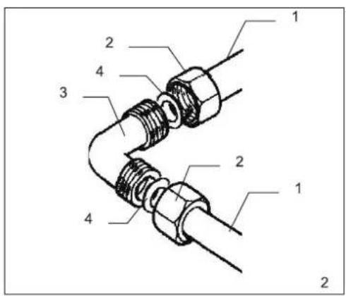
text_image
Technical diagram of a mechanical assembly with numbered components for identificationnatural_image
Hand holding a circular object with a black arrow pointing to it, labeled '3' (no text or symbols on the object itself)
natural_image
Hand holding a tool above a circular base, no text or symbols visible
text_image
Diagram showing a cooking step with pots and a magnified view of a cylindrical object on a dish, labeled '5'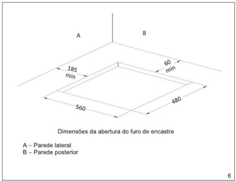
text_image
A B 185 min 60 min 480 560 Dimensões da abertura do furo de encastre A – Parede lateral B – Parede posterior 6
text_image
Série L mm P mm H mm 60 585 500 43
text_image
20 30 8 40 8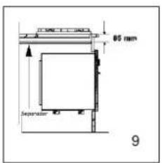
text_image
65 mm Separator 9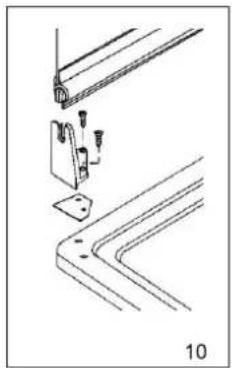
natural_image
Technical line drawing of a mechanical bracket assembly with mounting holes and mounting brackets (no text or symbols)
natural_image
Technical diagram showing a mechanical assembly with no visible text or symbolsnatural_image
Technical line drawing of a mechanical assembly with no visible text or symbols
text_image
Technical diagram of a pipe fitting with numbered components for identificationnatural_image
Illustration of a hand using a tool to press or install a circular component, with no visible text or symbols.
natural_image
Simple line drawing of a hand using a tool to press or test a circular object, no text or symbols present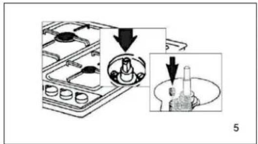
text_image
Diagram showing a gas stove with valve mechanism and a close-up of the internal components, labeled with number 5.
text_image
A B 185 mm 60 mm 480 6natural_image
Technical line drawing of a bent metal bracket assembly with mounting bracket and mounting bracket (no text or symbols)
natural_image
Technical diagram showing pipe connection and bracket assembly (no text or symbols)
Red de Asistencia en Portugal
http://goo.gl/qZ9s7
808 200 426
5 CARACTERÍSTICAS TÉCNICAS
| Quemadores | EE Quemadores % | Potencia gas W | Potencia eléctrica W | MG 3641 | MG 3631 | MG 3640 | MG 3650 |
| Auxiliar | 67 | 1 000 | ... | 1 | 1 | 1 | 1 |
| Semi-rápido | 66 | 1 750 | ... | 2 | 1 | 2 | 2 |
| Rápido | 64 | 3 000 | ... | 1 | 1 | 1 | ... |
| Wok | 61 | 4 000 | ... | ... | ... | ... | 1 |
| Placa | ... | ... | 1000 | ... | ... | ... | 1 |
| EE hornillo gas ( % | 66 | 66 | 66 | 65 | |||
| Máxima potencia gas W (PCS) | 7 500 | 5 750 | 7 500 | 8 500 | |||
| Máxima potencia eléctrica W | ... | 1000 | ... | ... | |||
| Máximo consumo gas propano - G 30 (g/h) | 546 | 412 | 546 | 558 | |||
| Máximo consumo gas butano - G 31 (g/h) | 536 | 428 | 536 | 567 | |||
| Máximo consumo gas natural - G 20 (L/h -1013 mbar, 15 è C) | 715 | 648 | 715 | 743 | |||
| Alimentación | 220 – 240 V ~ | 220 – 240 V ~ | — | 220 – 240 V ~ | |||
| Dimensiones : L x F x A mesa ( mm ) Embalaje | 610x110x680 | 610x110x680 | 610x110x680 | 610x110x680 | |||
| Peso : Bruto ( Kg ) | 9.5 | 9.7 | 9.5 | 9.5 | |||
INSTRUCTION MANUAL FOR
INSTALLATION
USAGE
MAINTENANCE
TABLE OF CONTENTS
- GENERAL WARNINGS .... 3
- USAGE INSTRUCTIONS....4
2.1 MAIN DEVICE COMPONENTS ....4
2.2 GAS BURNER OPERATION....5
2.2.1 BURNER IGNITION 5
2.2.2 ADVICE REGARDING GAS BURNER OPERATION....5
2.3 HOT PLATE OPERATION....6
2.3.1 ADVICE REGARDING HOT PLATE OPERATION 6 - MAINTENANCE AND CLEANING....6
- INSTALLATION....7
4.1 POSITIONING....7
4.2 GAS CONNECTIONS....8
4.3 ELECTRICAL CONNECTIONS 9
4.3.1 POWER SUPPLY CABLE CONNECTION 9
4.4 ADAPTATIONS FOR DIFFERENT GAS TYPES ....10
4.5 MINIMUM OUTPUT ADJUSTMENT 10
4.6 FLUSH-MOUNTING INSTRUCTIONS....11
4.6.1 PHYSICAL DIMENSIONS....11
4.6.2 STAINLESS STEEL OR ENAMELED HOTPLATES 11
6 FIGURES....12
5 TECHNICAL CHARACTERISTICS....15
1. GENERAL WARNINGS
Dear Customer,
Thanked you for having chosen our product. Usage of this device is very straightforward; before installing and using it, it is necessary that you read this manual carefully, where you can find instructions for the installation, usage and maintenance of this product.
- Please note: inside the package of the device you may also find the warranty certificate, which should be correctly filled out and sent within 8 days from the date of acquisition.
- It is very important that this instruction manual is conserved, along with the device, in case ownership is transferred.
• This device is class 3 and was designed for non professional, private indoor usage. - It should be used by adults and we therefore recommended not allowing children to play close by.
- Please monitor children during periods of usage so as to avoid that they touch hot surfaces or remain near the device during its operation.
- The installation of the product, relative to both gas and electrical systems, should be done by qualified technical personnel familiar with installation standards and the standards in force.
- Before powering on the device, verify that it is properly configured for the type of gas available (see the device's identification plate)
- Before proceeding with maintenance and cleaning operations, turn off the device at the mains/gas inlet and wait for it to completely cool down.
-
When the burners ignite, verify that the flame is constant. Before removing any pots/pans, we recommend you turn off the gas burners and electric hotplates.
-
The device's power cable (for models including it as standard) should never be replaced by the user. For its replacement, contact qualified technicians only.
- The use of gas appliances produces heat and humidity at the location in which they are installed. Check that the kitchen is well ventilated: maintain natural ventilation ports opened or install a mechanical ventilation device (mechanical exhaust duct).
- A prolonged and intensive use of gas appliances may require auxiliary ventilation, for instance the opening of a window or more effective ventilation, for increasing the mechanical ventilation level when present.
- The use of gas appliances requires a steady flow of air. Verify that the installation is performed with full compliance of the terms stated in paragraph 4.1 - Positioning.
- When using the cover, please remember to close it only after the burners have completely cooled down. Use the cover only as a protection mechanism for the device, not for other purposes.
- Please remember to never place pots with unstable or deformed bases on the burners or electric hotplates so as to avoid accidents caused by spilling liquid.
• In case of eventual repairs, always contact an authorized Technical Support Center and demand original spare parts. Repairs made my unauthorized personnel may cause damage.
2. USAGE INSTRUCTIONS
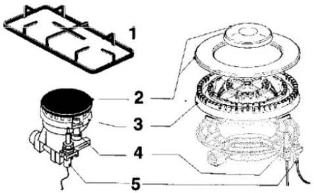
2.1 MAIN DEVICE COMPONENTS
The control section contains dials and devices for controlling operation of the gas burners and/or electric hotplates.
text_image
Technical diagram of a mechanical assembly with numbered parts, showing exploded and assembled views.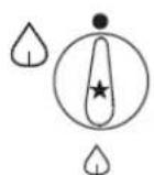
6
7

8
9

10
1 - Enameled grill
3 - Spreader
5 - Thermocouple (for versions equipped with valves)
7 - Hotplate control device
9 - Electric hotplate (if supplied)
2 - Enameled cover
4 - Spark plug (for versions equipped with ignition)
6 - Burner control dial (* for versions equipped with an ignition switch)
8 - Ignition switch (for versions equipped with ignition)
10 - Display for electric hotplate operation
The dials for burner regulation can be turned anti-clockwise from the off position until the minimum gas supply position and vice-versa in the clockwise direction (rotate the indicator to the desired position).
● = no gas supply
= full gas supply
△ = minimum gas supply
2.2.1 BURNER IGNITION
For models equipped with an electrical ignition mechanism, ignition of the burners is done by pressing in and turning the dial in the maximum flame output direction. For versions with a separate ignition button, simply press the ignition button and turn the dial corresponding to the desired burner until reaching the maximum flame output position.
For versions with no electrical ignition (or in case electrical power is unavailable), it is necessary to perform the operations described by first placing a flame close to the burner.
For models equipped with a safety valve, maintain the dial pressed during roughly 5 seconds until the device can maintain the flame lit on its own.
The safety valve is triggered in the event the flame is accidentally extinguished, blocking the gas outlet (i.e. in case of a draft, spill, etc).
In case the flame is accidentally extinguished or in case the ignition process was unsuccessful, turn off the command dial and repeat the process after roughly 1 minute.
Once the burner has ignited, regulate the flame according to your requirements.
To cut off the supply of gas, rotate the dial in the opposite direction until the « • » position is reached.
To reduce gas consumption and obtain better efficiency, we recommend using pots with diameters appropriate for each of the burners, thus guaranteeing that the flame is contained underneath (please refer to the container chart). Use flat-bottomed containers only. It is also advisable that as soon as the liquid begins to boil you regulate the flame to a lower level, enough to maintain the boiling point.
When using fats or oils, please note that once heated up these may become inflammable.
| Container Chart (use only flat-bottomed containers) | ||
| Burners(enameled cover diameter) mm | Pot min. diam.(cm) | Pot max. diam.(cm) |
| Auxiliary ( = 42 ) | 10 | 16 |
| Semi-fast ( = 62 ) | 15 | 22 |
| Fast ( = 92 ) | 20 | 26 |
| Wok ( = 130 ) | 24 | 30 |
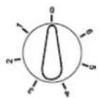
Certain versions are equipped with an electric hotplate. According to usage requirements, the hotplates can be regulated by turning the respective dials either clockwise or counterclockwise in 6 positions besides 0. The positions indicated by higher numeric values correspond to the maximum temperature. The lit indicator at the control section signals the use of the electrical hotplates.
| Heat up | Cook | Roast - Fry |
| 1-2 | 3-4 | 5-6 |
2.3.1 HOTPLATE USAGE
For greater electric hotplate service life and increased energy efficiency, we advise using only flat-bottomed containers whose diameter is inferior to that of the hotplates.
Prevent boiling liquids from overflowing and dripping onto the hotplates.
Never leave the hotplates turned on with no containers present or with containers which are empty.
Never use the electric hotplates to heat up the environment.
Turn on a hotplate only after having placed a container on top of it.
Please note that the hotplates, once turned off, still remain hot for some time.
3. MAINTENANCE AND CLEANING
Before performing any maintenance and cleaning operation, switch off the power to the device. We recommend washing the enameled parts with lukewarm water and detergent only; do not use abrasive products.
Wash the burner spreaders frequently with boiling water and detergent, making sure you eliminate all fouling and buildup which may clog flame output. Wash the stainless steel parts with water and rinse with a soft cloth.
For cleaning the device, use slightly wetted sponges and cloths; an excessive amount of water can infiltrate the internal areas of the device and eventually damage electrical parts.
The grills may be washed in the dishwasher.
For persistent stains, use normal non-abrasive detergents, specific commercially sold cleaning products or some warm vinegar. Clean the glass pane with hot water and a soft cloth.
It is not advisable to use steel wool, steel blades or acid.
To clean the electric hotplates, use wetted cloths and a light film of oil while the hotplate is still lukewarm.
Periodically or when excessive dial rotation resistance is verified, hire a qualified technician to lubricate the faucets (see figure 1).
Please contact qualified technicians so as to also eliminate eventual problems verified during usage.
4. INSTALLATION
This device belongs to category II2H3+(20;28-30/37), direct destination country PT.
The device was not designed to be hooked up to a combustion exhaust evacuation device. It should be set up and mounted in accordance with the applicable installation standards in force. Particular attention should be paid to ventilation requirements.
4.1 POSITIONING
The device should be installed and operated only in permanently ventilated environments, in accordance with the standards in force.
The natural flow of air should be made directly through permanent vents in the walls at the place of installation, which should be ventilated and connected to the exterior or by means of individual/branched ventilation tubes.
The vents should have a useful cross-section of at least 100 cm ^2 and should be protected against accidental obstructions (protected by metallic grills or mesh).
For devices without a safety valve on the working plane, venting cross-sections should be doubled, leading to a minimum cross-section of 200 cm ^4 .
Airflow can also be obtained indirectly through environments adjacent to those of the installation, as long as such areas are equipped with direct ventilation (with the exception of bedrooms or areas posing a fire hazard).
The flow of air between the adjacent areas and the installation area must be done freely by way of permanent venting (which may eventually be obtained by opportunely increasing the space between the door and the ground).
The installation area should foresee an exhaust system connected towards the exterior, which may be obtained by using a chimney or an extractor fan which is operated when the device is turned on.
4.2 GAS CONNECTIONS
Before installing the device, make sure that the local distribution conditions (gas type and pressure) are compatible with the configuration of the device itself.
The device is designed to work with the type and pressure of the gas stated on the packaging and on the label found on its lower portion.
The device must be connected in accordance with the standards and regulations in force.
In case the type of gas available does not correspond to the gas for which the device was designed, the injectors should be replaced and the old label should also be replaced with a new label, stating the new type.
For this type of operation, the qualified installer should follow the indications stated in the paragraph "Adaptations for different gas types".
Verify that the supply pressure respects the values indicated in the table "Burner and injector characteristics".
It is mandatory to secure a connection to the fixed gas installation by means of a copper or steel tube, or by using a stainless steel flexible tube, manufactured in accordance with the applicable standards.
The gas inlet tube on the device comes with a threaded plug to which the supplied elbow should be connected (ISO 228 -1/2 G male thread) (see figure 2).
The other end of the elbow should be connected to the rigid or flexible metallic supply tube. Do not to forget to place the supplied sealants on the two ends of the elbow connection.
In the event of assembly of disassembly of these parts, these sealants must imperatively be replaced.
Upon finishing the installation, verify that the tube has not been crushed or damaged by moving parts.
Important : When the device has just been installed, verify the sealant of every connection using a soap and water solution and never an open flame.
Warning :
The use of this gas appliance produces heat and humidity at the location in which it is installed. It must be ensured that good environmental ventilation is available by keeping the natural vents open or by installing an extractor fan with a chimney.
4.3 ELECTRICAL CONNECTIONS
Devices equipped with a power cable are designed to work with 230 V \~ alternating current having a frequency of 50/60 Hz, as indicated on the plate containing the device's technical data (located on the lower portion of the device).
The earth conductor is color-coded in green/yellow.
Connection of the device to the grid should be done by a qualified individual, in accordance with the safety standards in force.
In case the hotplates are installed above an oven, the electrical connection of both devices should be done separately, for electrical safety reasons as well as to facilitate removal of the device.
4.3.1 POWER SUPPLY CABLE CONNECTION
To directly connect to the grid, it is necessary to install a unipolar switch having a minimum aperture of 3 mm between the terminals of the device and the grid, adequate for the expected loads and in accordance with the safety standards in force. The green/yellow earth connector must not be cut off by the switch.
The brown electrical live wire must be connected to the supply grid live wire.
The power cable must be positioned so that no part of it would ever reach a temperature of over 50^ C at room temperature.
Before making the electrical connections, verify that the domestic switchboard and cutoff equipment are able to handle the load of the device (please refer to the type plate containing the device's technical data or to the table located within the instruction manual).
Also verify whether the power supply installation is endowed with an effective earth connection in accordance with the safety standards in force, and that the unipolar switch is accessible after the hotplates are installed.
The manufacturer refuses any responsibility for cases in which the safety standards in force are not adhered to.
4.4 ADAPTATIONS FOR DIFFERENT GAS TYPES
To adapt the device to a different type of gas from what it was designed for (refer to the label on the packaging and on the lower portion of the device), the following operations are necessary:
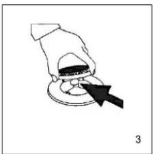
- Remove the grill
- Remove the enameled covers and spreaders (see figure 3).
- Use a 7 mm diameter tube key to remove the injectors (see figure 4)
- Replace the injectors with the ones corresponding to the type of gas available (refer to the table regarding burner and injector characteristics)
- Reassemble the different parts in the inverse order of the aforementioned operations. Do not forget to replace the old label with the new one (supplied)
4.5 MINIMUM OUTPUT ADJUSTMENT
Regulation of the minimum flame output is done at the factory. After an eventual replacement of the injectors, it is necessary to calibrate minimum flame output again. The necessary procedures for such are as follows:
- Ignite the burner
- Turn the dial towards the minimum output position
- Remove the dial (including the eventual mounted seal)
- Introduce an appropriately sized screwdriver and turn the regulation screw located inside or beside the faucet screw (see figure 5) until a small regular flame is obtained.
- Put the dial back in place and quickly turn it from the maximum to the minimum position, controlling the flame so that it is not extinguished.
- For burners supplied with a safety valve, verify that the regulation obtained is enough to maintain the heating of the probe, otherwise increase the minimum flame output.
The burners do not require primary air regulation.
4.6 FLUSH-MOUNTING INSTRUCTIONS
The equipment is classified as type Y, meaning it can be installed with only one lateral wall (to the right or to the left) with a height greater than that of the work plane and located at a minimum distance of 185 mm as illustrated in figure 6.
It can fit into every type of worktop having walls able to handle 65^ C above room temperature.
Avoid installing the equipment in places where inflammable materials (i.e.: curtains, dish cloths, etc.) are nearby.
4.6.1 PHYSICAL DIMENSIONS
These devices are designed to be mounted in worktops having a minimum depth of 550 mm.
The dimensions of the fitting slots are indicated in figure 6, where also stated are the minimum distances that should be respected between the slot and the eventual side piece 185 mm and the rear 60 mm.
The dimensions of the hotplates are indicated in figure 7.
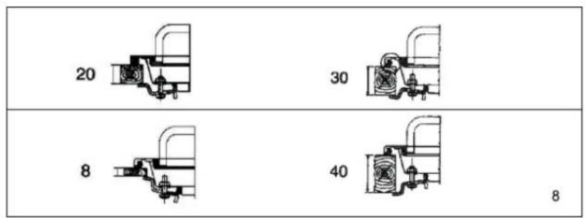
4.6.2 STAINLESS STEEL OR ENAMELED HOTPLATES
- Position the supplied seal within the perimeter of the plane, making sure that the ends coincide but do not overlap.
- Introduce the plane into its place of installation, making sure that it is well centered.
- Secure the plate to the worktop using the respective support brackets (see figure 8). The traction of the screws is enough to cut the seal so that the excess can be easily removed.
Warnings
Any piece of furniture suspended over the work plane must be at a minimum distance of 600 mm from the plane.
To avoid overheating, a separation gap may be necessary in case the hotplates are installed above an oven (see figure 9). This gap is also recommended in case a triple burner is present.
António Meireles, S.A.
6 FIGURES
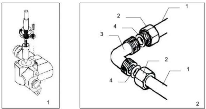
1 - Gas manifold - Metallic supply tube
2 - Nut
3 - Elbow
4 – Sealing ring
natural_image
Illustration of a hand using a tool to press or adjust a circular component, with no visible text or symbols.
natural_image
Simple line drawing of a hand using a Bunsen burner to test a test tube on a circular base (no text or symbols)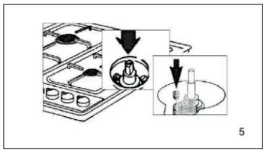
text_image
Diagram showing a cooking step with a stove and a bowl, labeled with arrows and page number 5
text_image
A B 185 min 60 min 480 6Flush-mounting bore size

text_image
A - Side wall B - Rear wall| Series | Wmm | Lmm | Hmm |
| 60 | 585 | 500 | 43 |

text_image
85 mm Separator 9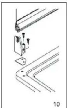
natural_image
Technical line drawing of a mechanical bracket assembly with mounting holes and a base plate (no text or symbols)
natural_image
Technical diagram showing a mechanical assembly with no visible text or symbols
Service Network in
Portugal
http://goo.gl/qZ9s7
808 200 426
5 TECHNICAL CHARACTERISTICS
| Burners | EE Burners % | Gas power W | Electrical power W | MG 3641 | MG 3631 | MG 3640 | MG 3650 |
| Auxiliary | 67 | 1 000 | ... | 1 | 1 | 1 | 1 |
| Semi-fast | 66 | 1 750 | ... | 2 | 1 | 2 | 2 |
| Fast | 64 | 3 000 | ... | 1 | 1 | 1 | ... |
| Wok | 61 | 4 000 | ... | ... | ... | ... | 1 |
| Hotplate | ... | ... | 1000 | ... | ... | ... | 1 |
| EE gas ( % | 66 | 66 | 66 | 65 | |||
| Maximum gas power W (PCS) | 7 500 | 5 750 | 7 500 | 8 500 | |||
| Maximum electrical power W | ... | 1000 | ... | ... | |||
| Maximum propane gas consumption - G 30 (g/h) | 546 | 412 | 546 | 558 | |||
| Maximum butane gas consumption - G 31 (g/h) | 536 | 428 | 536 | 567 | |||
| Maximum natural gas consumption - G 20 (L/h -1013 mbar, 15 è | 715 | 648 | 715 | 743 | |||
| Power supply | 220-240 V~ | 220-240 V~ | — | 220-240 V~ | |||
| Physical dimensions : W x D x H table ( mm ) Packaging | 610x110x680 | 610x110x680 | 610x110x680 | 610x110x680 | |||
| Weight : Gross ( Kg ) | 9.5 | 9.7 | 9.5 | 9.5 | |||
EE Burner - Complies with (EU) 66/2014
The manufacturer assumes no responsibility regarding eventual printing errors contained in this manual.
The manufacturer reserves the right to, at any moment, make eventual changes deemed necessary or useful.