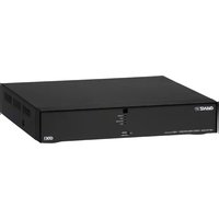
PixelMaster GXi NR1-4F23S - Security Camera Ganz - Free user manual and instructions
Find the device manual for free PixelMaster GXi NR1-4F23S Ganz in PDF.


| Product Type | Security Camera |
| Model | PixelMaster GXi NR1-4F23S |
| Brand | Ganz |
| Dimensions (W x H x D) | 150 mm x 120 mm x 100 mm |
| Weight | 0.8 kg |
| Power Supply | 12V DC, 1A |
| Resolution | 2 Megapixels (1920 x 1080) |
| Night Vision | Up to 30 meters with IR LEDs |
| Lens | 4-23 mm varifocal, F1.4 |
| Field of View | 80° to 30° (adjustable) |
| Video Compression | H.265, H.264 |
| Weatherproof Rating | IP66 |
| Motion Detection | Yes, with alarm output |
| Audio Support | Built-in microphone and speaker |
| Storage | MicroSD slot up to 256 GB |
| Connectivity | Ethernet (PoE), Wi-Fi optional |
| Operating Temperature | -30°C to 60°C |
| Maintenance | Clean lens with soft dry cloth; check connections periodically |
| Safety | CE, FCC, RoHS compliant |
| Spare Parts | Mounting kit, power adapter available from Ganz |
| Repairability | Professional repair recommended; contact Ganz support |
| General Information | User manual available on notice-facile.com; 96 pages |
Frequently Asked Questions - PixelMaster GXi NR1-4F23S Ganz
User questions about PixelMaster GXi NR1-4F23S Ganz
0 question about this device. Answer the ones you know or ask your own.
Ask a new question about this device
Download the instructions for your Security Camera in PDF format for free! Find your manual PixelMaster GXi NR1-4F23S - Ganz and take your electronic device back in hand. On this page are published all the documents necessary for the use of your device. PixelMaster GXi NR1-4F23S by Ganz.
USER MANUAL PixelMaster GXi NR1-4F23S Ganz
HD1080p 4ch / 8ch / 16ch
Network Video Recorder
PIXEL
MASTER
WITH

NVR
Before connecting, operating or adjusting this product, read this instruction booklet carefully and completely
TABLE OF CONTENTS
1. BEFORE INSTALLATION 4
1.1 UPDATING SYSTEM F/W 5
1.1.1 WITH THE USB THUMB DRIVE 5
1.1.2 UPDATING FROM THE WEB MENU 7
1.2 DESCRIPTION OF FRONT PANEL 9
1.3 DESCRIPTION OF REAR PANEL.... 10
1.4 DESCRIPTION OF PIN ASSIGNMENT 11
2. GETTING STARTED 13
2.1 CONNECT AND SWITCH ON 13
2.2 START SETUP 13
2.3 LOADING....14
3. Live View....15
3.1 TOOL BAR 15
3.1.1 STATUS DISPLAY 16
3.1.2 LOG OFF 16
3.1.3 SETUP 17
3.1.4 VA (Video Analytics).... 17
3.1.5 QUICK COPY 18
3.1.6 SEARCH....18
3.1.7 DISPLAY 18
3.1.8 PTZ 19
3.1.9 DIGITAL ZOOM 19
3.1.10 LOG LIST 21
4. SEARCH & PLAYBACK 22
4.1 TIME / CALENDAR SEARCH....22
4.2 PANORAMA SEARCH 24
6. HOW TO CONFIGURE....31
6.1 CONFIGURING CAMERA....31
6.1.1 TITLE 31
6.1.2 ADJUST 32
6.1.3 PTZ 33
6.1.4 CAM PORT 33
6.1.5 VIRTUAL PORT 36
6.2 CONFIGURING DISPLAY 37
6.2.1 OSD 37
6.2.2 MONITOR 38
6.2.3 SEQUENCE.... 39
6.3 CONFIGURING DISK 40
6.3.1 SETUP 40
6.3.2 FORMAT 42
6.4 CONFIGURING SYSTEM 43
6.4.1 DATE TIME 43
6.4.2 MANAGEMENT 43
6.4.3 SOUND 45
6.5 CONFIGURING EVENT / SENSOR 46
6.5.1 SENSOR INPUT 46
6.5.2 ALARM OUTPUT SETUP 46
6.5.3 BUZZER OUTPUT SETUP 47
6.5.4 E-MAIL SETUP 48
6.6 CONFIGURING USER 49
6.6.1 USER REGISTER 49
6.6.2 USER AUTHORITY 50
6.6.3 LOG-OUT 50
6.7 CONFIGURING RECORD....51
6.7.1 MAIN STREAM....51
6.7.2 SUBSTREAM 52
6.7.3 SCHEDULE 53
6.7.4 OPTION 54
6.8 CONFIGURING NETWORK 56
6.8.1 ETHERNET PORT 56
6.8.2 LOCAL PORT 57
6.8.3 DDNS 57
6.8.4 E-MAIL 58
7. REMOTE....59
7.1 WEB SERVER 59
7.1.1 CONNECT TO WEB SERVER 59
7.1.2 WEB CONFIGURATION PAGE 61
7.1.3 WEB VIEWER (Active-X)....62
7.2 Android Viewer / iOS Viewer....71
7.2.1 How to use....71
DDNS SERVER 74
7.3.1 HOW TO REGISTER....74
7.3.2 REGISTER 74
7.3.3 Input NVR information. 75
7.4 DVR MANAGER 76
7.4.1 INSTALLATION....76
7.4.2 EXECUTION 77
7.4.3 LIVE VIDEO MONITORING 77
7.4.4 CONNECTION MANAGER 78
7.4.5 LIVE VIDEO WINDOW 80
7.4.6 PLAYER 84
7.5 FILE PLAYER 92
8. Appendix A....95
1. BEFORE INSTALLATION
The Company shall not have any responsibility for any accident or damage that may incur during the use of the product.
For your safety, we provide a few instructions about installation, manipulation, cleaning, assembly/disassembly of the product as below.
So please read carefully and comply with the instructions.
Before installation
Comply with the following instructions to prevent a fire, explosion, system failure or electric shock.
◇ Remove the power supply module before proceeding.
Check the input voltage (AC100V-AC240V) to the power supply module before connecting it.
✧ Keep the product away from humidity.
- Ensure that all devices connected to the product should be properly earth-grounded.
In operation mode
Comply with the following instructions to prevent a fire, explosion, system failure or electric shock.
If you need to open the cover, consult with a service person who could help you do what you want to do.
Do not connect multiple devices to a single power socket.
Keep the product away from dust or too much combustible substances (ex: propane gas).
Do not touch it with wet hand.
Do not insert a conductor in the vent of the ventilation system.
Do not apply excessive force to unplug the power cord.
Disassembly & Cleaning
When cleaning on the surface, use a dry cloth.
Do not wipe the product using water, paint thinner or organic solvents.
Do never dismantle, repair or modify the product by your own.
During installation
To prevent an accident or physical injury and to operate NVR properly, please comply with the followings.
Secure at least 18 centimeter of distance between cooling fan and wall for a proper ventilation.
✨ Install the product on a flat surface.
✿ Keep it away from direct sunlight or excessive temperature.
While in use
Do not apply force to or shake it while using it.
Do not move, throw away or put excessive force to it.
Using any un-recommended HDD may cause a system failure. Check the compatibility list and use only compatible HDDs.
✿ {A system failure or data loss caused by an incompatible HDD will void your warranty.}
1.1 UPDATING SYSTEM F/W
1.1.1 WITH THE USB THUMB DRIVE
User can upgrade the system firmware by himself if required. F/W upgrading could be required to increase the stability and the reliability or apply the new updated features. The following steps are a progress to upgrade the f/w.
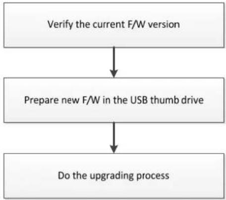
flowchart
graph TD
    A["Verify the current F/W version"] --> B["Prepare new F/W in the USB thumb drive"]
    B --> C["Do the upgrading process"]
1.1.1.1 How to verify the F/W version
You may need to check the F/W version provided and the F/W version currently used in the system. From the Setup=>SYSTEM=>MANAGEMENT, you can see the current version of F/W.

F/W version of new provided one: From the filename of the provided F/W file, you can see the version number.
Check the F/W version.

The ^1,0,9 V1.0.0' in the file name means the F/W version.
Do not update F/W if the version number of F/W file is lower than the current F/W version.
1.1.1.2 Preparing new F/W in the USB thumb driver
1) Unzip firmware file.

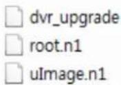
After unzip, you can see above system file.
According to Upgrade field, number of downloaded file would be different.
2) Make the 'dvr' folder at the root of the USB thumb drive.
The characters, 'd', 'v', 'r', in the folder name have to be a lower case not a capital.
3) Copy the released F/W zip file into the 'dvr' folder in the USB thumb drive.
1.1.1.3 Upgrading System from the System Menu
Following steps will guide you into the way to upgrade the system with the new F/W.
1) Plug the prepared USB thumb drive in the USB port of NVR.
2) Open Setup=>SYSTEM=>MANAGEMENT menu.

The whole upgrading process may take about ten minutes.
DO NOT remove the USB thumb driver during upgrading.
DO NOT turn off power of system during upgrading.
4) If the firmware upgrade is finished, system will be rebooted automatically.
1.1.2 UPDATING FROM THE WEB MENU
The web menu service prepared in the NVR provides the way to update the system F/W remotely. The following steps explain how to do this.
To know the way how to access the internal web menu service, refer the section 7.1, 'WEB SERVER' of this user's guide.
1) Login the NVR through the web server.
2) Enter the 'SYSTEM MANAGEMENT' page under the 'SYSTEM' menu page. Refer to the below picture.
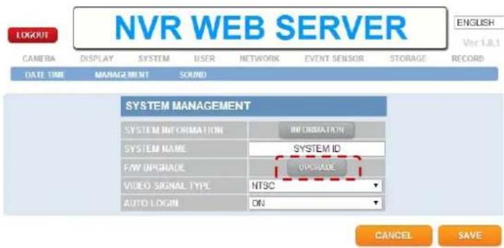
3) Click the button 'UPGRADE' and open the update page.
4) In the update page, click the 'BROWSE' button and call the file open window.
5) Choose the provided F/W files which has the file extension 'tar.gz or tgz'.

6) Click the 'F/W UPLOAD' button and let the system uploading the F/W into the system.
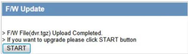
7) When uploading is finished successfully, the system is going to be ready to update and wait to start. Click the 'START' button triggers the updating processes.
8) While the update is on, the progress steps will appear such as below.
![Firmware Update - Windows Internet Explorer http://192.168.123.59/cgi-bin/php/htdocs/system/fw_update.php F/W Update Starting F/W Upgrade. Firmware Update - Windows Internet Explorer http://192.168.123.59/cgi-bin/php/htdocs/system/fw_check.php F/W Update F/W Uploading : UPGRADING STEP 1/3 [KERNEL-0] - 88(%) Uploading, Do not close this window. Firmware Update - Windows Internet Explorer http://192.168.123.59/cgi-bin/php/htdocs/system/fw_check.php F/W Update F/W Uploading : UPGRADING STEP 3/3 [ROOT-1] - 100(%) Uploading, Do not close this window.](/content/2026/06/1170201/images/6627063cb9c58406950bc7d8752156a17b2c349185ee8c983358b57cc4d63da3.jpg)
9) System shows the [COMPLETE] when update finished and reboot automatically.
10) When the whole update is completed, the NVR will restart.
Turning off the power in any process of F/W updating cause the damage of the system.
1.2 DESCRIPTION OF FRONT PANEL
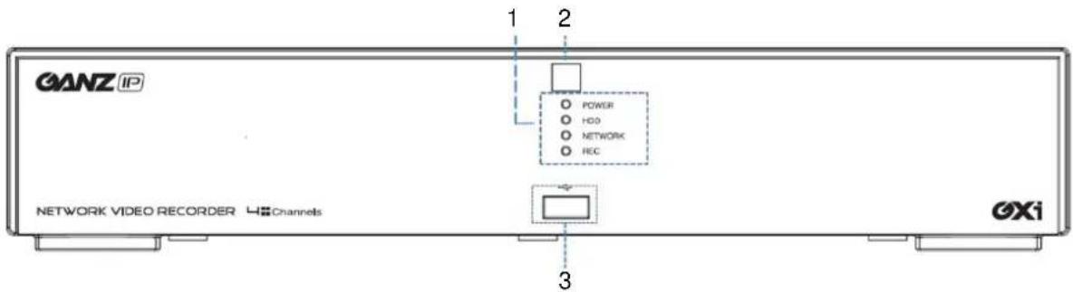
[Front panel 4ch NVR]
1. STATUS LED
Displays the information of the NVR (Stand - By), Record / HDD read/write and Network transmission.
2.IR RECEIVER
Infrared signal receiver for the IR remote control.
3.FRONT USB 2.0 PORT
USB 2.0 ports. Provides functions like 'Copy to USB storage', 'F/W Upgrade' and 'mouse' operation.

[Front panel of 8 & 16CH NVR]
1. IR RECEIVER
Infrared signal receiver for the IR remote control.
2. STATUS LED
Displays the information of the NVR (Stand -By), Record and Network transmission.
3.FRONT USB 1/2 2.0 PORT
USB 2.0 ports. Provides functions like 'Copy to USB storage', 'F/W Upgrade', 'mouse' operation.
1.3 DESCRIPTION OF REAR PANEL

[Rear panel of 4CH NVR]

[Rear panel of 8 & 16CH NVR]
1. Power Switch
Switch to turn the NVR ON & OFF.
2.VGA Output (Video Graphic Array)
15-pin D-sub connector for the analogue VGA output.
3. Audio Inputs
RCA connectors for the audio signal inputs. (Line In)
4.Power In
12V DC Power socket.
5. Alarm(Sensor) Inputs, RS-485, and Relay Output
- Alarm inputs x 4
- RS-485 Signals. (G: Ground, D+: RX/TX + signal, D-; RX/TX- signal)
- 4CH NVR: Relay output for the relay 1 (NO: Normal Open, NC: Normal Closed, CM: Common)
- 8&16CH NVR: Relay output for the relay 2 (NO: Normal Open, NC: Normal Closed, CM: Common)
6. Rear USB 2.0 (Only the 4CH NVR)
USB 2.0 ports. Provides functions like 'Copy to USB storage', 'Mouse' and Etc.
7. DIGITAL VIDEO OUT (HDMI)
Digital video output for the main monitor.
8. CVBS Monitor Output
Composite video output for the main live screen or the spot screen. (BNC)
9.RJ-45 Network Port(1G Base-T)
Network port is used to 1G base-T, PC application software or Mobile application.
10.RJ-45 Local Port( 1G Base-T)
User can make a connection between IP camera and NVR through this port in case of using local network already installed. IP address will be automatically assigned as 192.168.172.100.
11.RJ-45 Cam(PoE) Port (100M Base-T)
User can make a connection between IP camera and NVR as peer to peer mode(direct connection). IP address will be assigned in the range of 192.168.172.101 \~ 8, automatically. (4CH NVR: 4ports / 8&16 NVR: 8ports)
12. Audio Outputs
RCA connectors for the audio signal outputs. (Line out)
13.PoE Power In (48V)
DC Power socket for POE Power.
14.eSATA Connection Port(Option)
connect e-SATA storage to expand HDD
1.4 DESCRIPTION OF PIN ASSIGNMENT
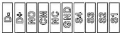

natural_image
Grid of green circular icons arranged in rows and columns, no text or symbols present[Terminal block of 4CH NVR]
| Pin | I/O | Description |
| D- I | 485 | – data signal |
| D+ | I | 485 + data signal |
| NO | O | Relay output (Normal Open) |
| CM | - | Relay Ground |
| NC | O | Relay output (Normal Close) |
| GND | - | Sensor Ground |
| S4 | I | Sensor 4 |
| S3 | I | Sensor 3 |
| S2 | I | Sensor 2 |
| S1 | I | Sensor 1 |

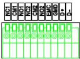
[Terminal block of 8CH NVR]
| Pin | I/O | Description |
| S1 | | | Sensor 1 |
| S2 | | | Sensor 2 |
| S3 | | | Sensor 3 |
| S4 | | | Sensor 4 |
| S5 | | | Sensor 5 |
| S6 | | | Sensor 6 |
| S7 | | | Sensor 7 |
| S8 | | | Sensor 8 |
| GND | - | Sensor Ground |
| NC1 | O | Relay 1 output (Normal Close) |
| CM1 | - | Relay 1 Ground |
| NO1 | O | Relay 1 output (Normal Open) |
| NC2 | O | Relay 2 output (Normal Close) |
| CM2 | - | Relay 2 Ground |
| NO2 | O | Relay 2 output (Normal Open) |
| ENG | - | Reserved |
| GND | - | 485 Ground |
| D+ | | | 485 + data signal |
| D- | | | 485 – data signal |

[Terminal block of 16CH NVR]
| Pin | I/O | Description | |
| S1 | | Sensor1 | ||
| S2 | | Sensor2 | ||
| S3 | | Sensor3 | ||
| S4 | | Sensor4 | ||
| S5 | | Sensor5 | ||
| S6 | | Sensor6 | ||
| S7 | | Sensor7 | ||
| S8 | | Sensor8 | ||
| GND | - | Sensor Ground | |
| S9 | | Sensor9 | ||
| S10 | | | Sensor 10 | |
| S11 | | | Sensor 11 | |
| S12 | | | Sensor 12 | |
| S13 | | | Sensor 13 | |
| S14 | | | Sensor 14 | |
| S15 | | | Sensor 15 | |
| S16 | | | Sensor 16 | |
| GND | | | Sensor Ground | |
| NC1 | O | Relay 1 output (Normal Close) | |
| CM1 | - | Relay 1 Ground | |
| NO1 | O | Relay 1 output (Normal Open) | |
| NC2 | O | Relay 2 output (Normal Close) | |
| CM2 | - | Relay 2 Ground | |
| NO2 | O | Relay 2 output (Normal Open) | |
| ENG | - | Reserved | |
| GND | - | 485 Ground | |
| D+ | | | 485 + data signal | |
| D- | | | 485 – data signal | |
2. GETTING STARTED
Controlling and setting NVR by remote control is limited to some of function, recommend you to use mouse operation of NVR for using all the function.
2.1 CONNECT AND SWITCH ON
Please check if power of IP camera is turn on.
Connect one or more monitors to NVR using Digital Video output or VGA.
Connect power to NVR. Press the power button on the back panel of NVR to begin operation.
When you make system boot up, you can view following system loading process after boot up logo image.

[Logo Image]
Depending on Monitor which you connect to NVR, initial logo is not displayed because your monitor is not support low resolution, so it is not a defect.
Initial set resolution is 1024 x 768, so you should use monitor higher than 1024x768
2.2 START SETUP
When you turn on at first time you can see the below menu.

SYSTEM LANGUAGE: Select the system language.
SYSTEM TIMEZONE: Select the system time-zone.
DATE FORMAT: Select the date format
VIDEO SIGNAL FORMAT: Select the video signal type
VIDEO OUTPUT RESOLUTION: Select the video output resolution.
Preview : You can check the preview of video resolution
The items which is defined in the 'START SETUP' would not be initialized after the factory default.
The settings in the 'START SETUP will replace the factory default value of each setting. After the factory default in the setup menu, the items defined in 'START SETUP' will have the values selected here.
2.3 LOADING

[Loading....]
When NVR is prepared for initial operation, display system preparing screen as above and show booting progress.
From loading screen display, recording starts according to pre-set condition.
- When loading, screen could be flashed, happening odd color while NVR is processed to optimize display.
When NVR is ready, Live view screen will be shown as below.

If start-up diagnostics are complete, the operator must log-in to the system. You need to type the default user name as "ADMIN" and the default password as "1234" and press the enter button
![LOG IN USER ADMIN PASSWORD 1 2 3 4 5 6 7 8 9 0 - = W Q W E R T Y U I O P [ J ] A S D F G H J K L : ' Enter Z X C V B N M . . / Space A OK](/content/2026/06/1170201/images/dbad0341b0e57201e9b013f8557324839f39f2d5057983d2b7be919c6e40a94e.jpg)
[Log-In]
3. Live View

[live mode of 4 channels]
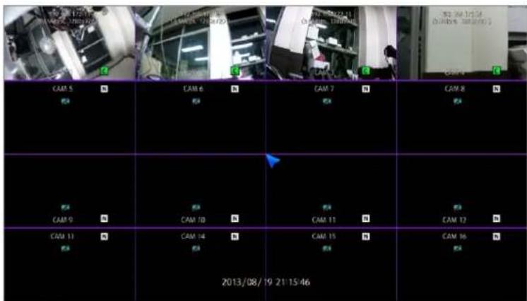
[live mode of 16 channels]
Recommend you to connect camera first before NVR starts.
3.1 TOOL BAR
You can view following Tool Bar when you move the mouse to the bottom of Live Screen.
The Tool-box display when mouse pointer move to bottom of screen, disappear after pre-defined menu setting time or exit with exit button (☐) in the menu you can set with all-time display.

3.1.1 STATUS DISPLAY
You can check current time / Network connection / USB storage connection/ Auto sequence/ HDD location currently recorded / Audio.
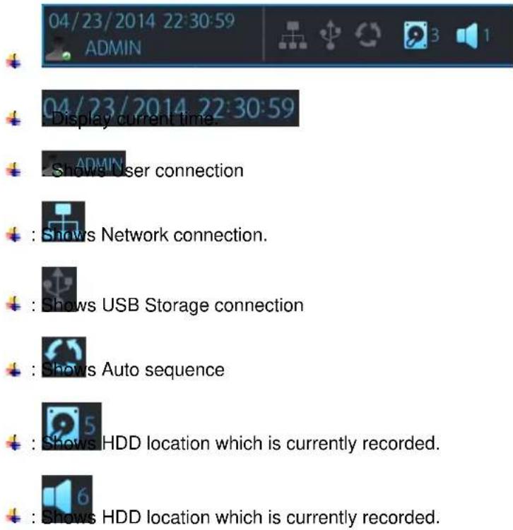
3.1.2 LOG OFF
There are two way for log off.
One is manual log off and the other one is automatic log off after configured time passed.
[Log-Off by using TOOL BAR]

Once Log off selected as above, current account can be log off.

You can set up auto log off in SETUP/USER/LOGOUT menu. Refer to 6.6.3 LOGOUT.
3.1.3 SETUP
If you press main menu button, main menu will be POP-UP.

3.1.4 VA (Video Analytics)
This menu is for using IP camera which supports Video Content Analytics.
NVR doesn't support VA configuration of IP camera. Following menu is for NVR which can handle VA meta data coming from VA supported IP camera.

[VA MENU]

VCA EVENT RECORD: You can configure record schedule once VA event activated from IP camera.
VCA ONLY: NVR records only VA event.
VCA OFF: NVR doesn't recognize VA event as real event.
VCA+MD: NVR recognize VA event and motion event both as an event.
SEND E-MAIL: NVR sends email once VA event recognized.
ATTACH SNAPSHOT: You can select ether attaching snapshot onto notification email or not.
VCA POPUP : When VCA event happen, event channel will be changed to full screen.
VCA POPUP DWELL: You can configure the duration for VCA POPUP.
VCA ICON DISPLAY: NVR display VA icon on live screen.
VCA BOX DISPLAY: NVR display VA box on live screen.
VCA ZONE DISPLAY: NVR display VCA zone on live screen.
BUZZER: You can configure buzzer on /off when VA event triggered.
RELAY: You can configure relay on/off when VA event triggered.
3.1.5 QUICK COPY
If you click following icon, instant Backup menu will be pop up. You can save the data 10 minutes from the current time.

3.1.6 SEARCH
To search a particular section of recorded footage, press the SEARCH button.
To protect unauthorized viewing of footage, only authorized users can playback footage.

3.1.7 DISPLAY
You can configure display mode by pressing display button of Tool bar.

You can select Quad / Single/ Auto sequence by selecting item in pop-up menu.

natural_image
Five grayscale grid and circular icons arranged horizontally (no text or symbols)
3.1.8 PTZ
You can move to the PTZ control mode.
When the display mode is split screen, the PTZ control panel will be opened for the selected camera which is previously highlighted by mouse click. If there is no highlighted camera, the PTZ control panel is opened for controlling the camera 1. In single display mode, the PTZ control panel is opened for the currently displayed camera.

[PTZ Controller Screen]
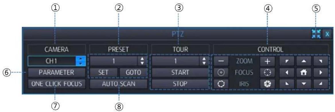
1: Select channel for PTZ control.
2: Number to configure Preset.
3: Select the tour function start or end.
4: Control the PTZ.
5: Change the size of control box.
6: Display PTZ control parameters which are set under the 'DETAIL' of PTZ menu settings
7: execute the automatic focus.
8: execute the auto scan.
3.1.9 DIGITAL ZOOM

[Zoom by using TOOL BAR]
At Full screen mode, you can enter Digital Zoom mode with this button.
In case opening digital zoom at Split screen mode, if there were pre-selected channel using mouse, then move to that channel's camera, if there were no pre-selected camera, goes 1ch camera for digital zoom

![Ganz PixelMaster GXi NR1-4F23S - [Zoom by using TOOL BAR] - 2](/content/2026/06/1170201/images/a0aba51fca434e29dfdb0072ffeb268cf137b0c7b010b237cc4cec08864ec775.jpg)
![Ganz PixelMaster GXi NR1-4F23S - [Zoom by using TOOL BAR] - 3](/content/2026/06/1170201/images/681e87e358da6fe2bef70a1ebf0443f11c50b611a9ba899166a5a027adb1cec3.jpg)
move Zoom area with arrow buttons.
![Ganz PixelMaster GXi NR1-4F23S - [Zoom by using TOOL BAR] - 4](/content/2026/06/1170201/images/6cb45821320e1f4bfdceb3d624bd32b8f8c20b2c8121a48c2bf8c44371fb7138.jpg)
![Ganz PixelMaster GXi NR1-4F23S - [Zoom by using TOOL BAR] - 5](/content/2026/06/1170201/images/4a0a0c742f0261e785434f301e778c1a763f55c63a727b4fd56139bdccd98ffc.jpg)
: If you press this button, zoom ratio will be changed for 1x to x5
[Zoom by using Mouse]

At full screen mode, you can select the area to zoom in by clicking left button of Mouse. (Drag), Clicking on the zoomed screen, the display returns to the original full screen mode.
Digital Zoom supported at Live / Play mode
Digital Zoom supported at only Full screen mode.
3.1.10 LOG LIST
You can view the log list by selecting log list button in Tool bar.

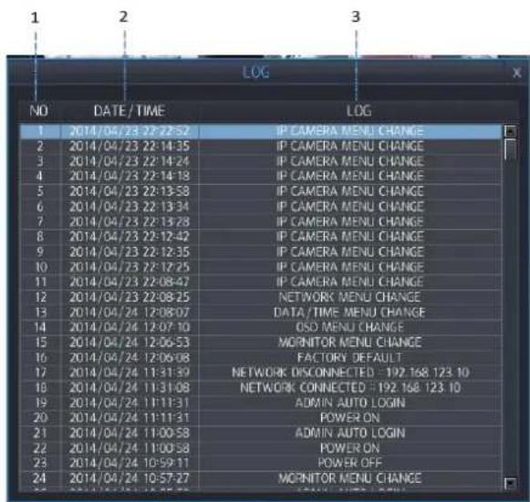
1 : Display number from currently triggered ( Max 10,000 list can be recorded)
2 : Date / Time
3: Log list
Items listed in log list. (Please refer to appendix:A)
4. SEARCH & PLAYBACK
4.1 TIME / CALENDAR SEARCH
You can search the recorded data by a calendar and timeline for quick access to recorded footage.
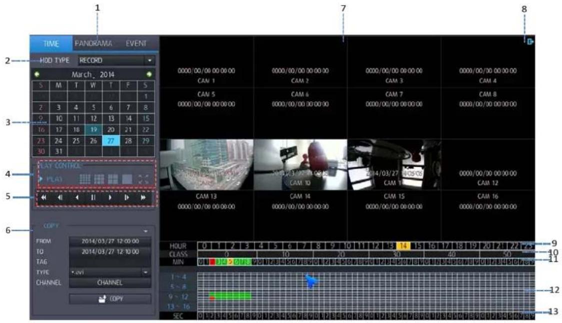
1 : Search Mode : You can select the search mode.
TIME: The recorded data can be searched using the calendar.
PANORAMA: If you select the channel for panorama view, search mode will be changed to PANORAMA Mode
EVENT: The recorded data can be searched using the event list.
2 : SEARCH HDD : You can select the HDD to search
RECORD: You can search HDD which is selected as Record.
MIRRORING: You can search HDD which is selected as Mirroring.
3: CALENDAR: If the data recorded in each date, orange color will be displayed.
If you select the date having the recorded data, you can make a display of recorded data by hour.
- Select Split screen


In full screen mode, playback control can be performed by control box.
In single screen mode, digital zoom function will be available.
: Return to Search menu.
: Close playback screen and return to live screen
5: PLAY CONTROL: Playback speed and direction control.

6: COPY: You can copy the data to external device.
7: VIDEO WINDOW: Playback video will be displayed
8: EXIT : Exit search menu and return to live menu.
9: HOUR SELECT LINE: You can select the data by hour. If certain time has recorded data, GREEN (Continuous) or RED (Event) color will be displayed.
10: CLASS / Minutes range display (10 minutes order).
11: MINUTE SELECT LINE: You can specify the minutes range to search recording data.
12: RECORD DATA STATUS: Recording data status of each channels. GREEN (Continuous recording), RED (Event Recording), YELLOW(Selected time)
13: SECOND SELECT LINE: You can select the recording data in second.
4.2 PANORAMA SEARCH
Panorama search supports hour/minute/second based search in 16ch view mode.
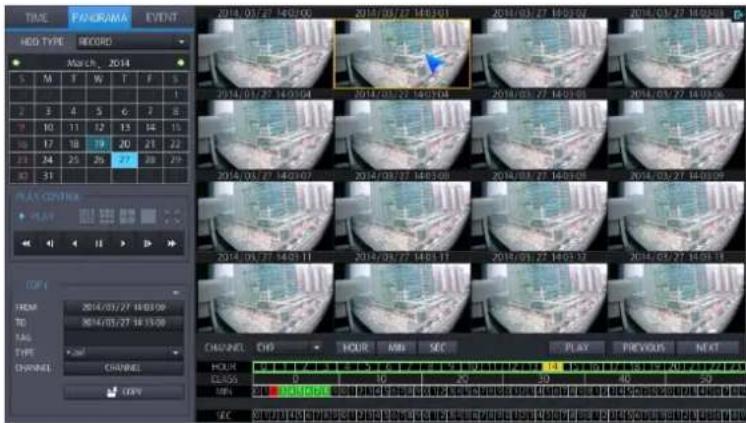
1) Select Channel form dropdown list to do panorama search.
2) Select the date of Calendar, thumbnail image by hour will be shown in display window. (It will be shown from first recorded data in selected date.)
3) Select one of the thumbnail images when you want to search by minute.
4) Select one of the thumbnail images when you want to search by second.
5) Click "PLAY" to start playback in single screen mode for selected channel.

4.3 EVENT SEARCH
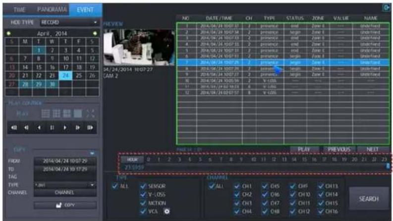
You can search recording data by Event. When you selected date of calendar, event search will be started automatically in the specified day.
Event list shows 20 event per page from the latest event, maximum 25page can be searched. (500 event)
Event list exceed 500 events, please re-search by adjusting event search period by time slider bar.

- Select date which you want to search event.
2: Preview: Events selected in the list displays a preview of the record. - Search result: event list displayed.
Maximum 500 events will be shown in the list.
No: Number of event display, recent event display with No.1
➢ DATE/TIME: Display Event triggered time.
CHANNEL: Display Event channel
➢ EVENT TYPE: Display Event type.
VCA function supported only for PixelPro GXi camera with auto connection mode.
STATUS (VA only) : Display VA event's "begin" or "end".
➢ ZONE (VA only) : Display zone number of VA event.
➢ VALUE (VA only) : In VA event, display event information requiring value.
➢ NAME (VA only) : Display registered name of VA event
4: You can select Event Type will be displayed in Event list.
ALL: Display all events.
➢ SENSOR: Display Sensor Event.
➢ VIDEO LOSS: Display Video loss Event.
➢ MOTION DETECTION: Display Motion Event.
VCA: Display VCA Event (Available for PixelPro GXi camera).
- VCA set up in detail: Search condition of VCA event set up in detail.
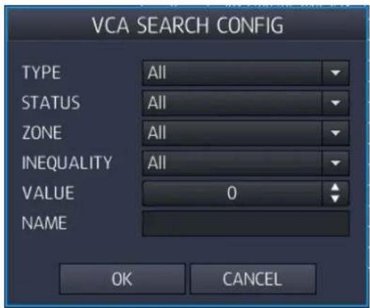
➢ 1 : TYPE : You can select which Type of VA will be displayed in VA list.
➢ 2 : STATUS : You can select start/end time of VA events.
3 : ZONE : You can select the zone of VA events.
4 : INEQUALITY : You can select the range of the value of VA events.
➢ 5 : VALUE : You can select the value of VA events.
6 : NAME : You can input ID of VA events which is "Object classifier" possible..
6: Search for events by hours / minutes can be selected.

7: You can select channel which will be displayed in Event list.
8: Switch Events List page. A total 500 events are shown on page 25.
9: You can configure a search condition again by stepping above 4 \~ 7.
4.4 COPY
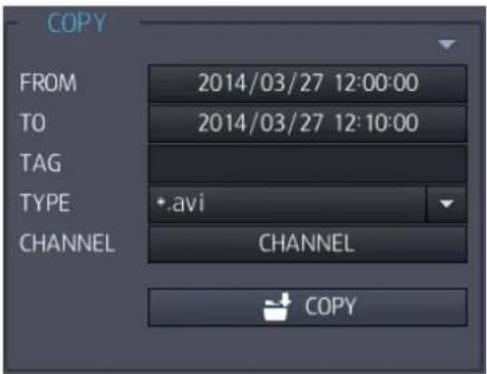
FROM: Specify the stat time to copy.
TO: Specify the end time to copy.
TAG NAME: Please enter Tag name. Tag name will be used to Folder and File name.
AVI format
Folder : "TAG" "CH"
File Name : "TAG"_CH"_Resolution"_FrameRate"_StartTime"_EndTime".avi
(Example) : \test11_CH1\ test11_CH1_1920_1080_15fps_140512_130103_140512_130500
DVR format
File Name : "TAG"_"StartTime"_"EndTime".dvr
(Example) : test11_140512_130103_140512_130500.dvr
TYPE: You can select the copy format.
*.avi: Format that can be played on standard AV player.
*dvr: Original recorder format. It can be played in multiple screen mode. on unique file player.
CHANNEL: You can select the channel to copy.
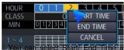
- You can select Start/End Time at Calendar search on Time line to copy.
Copy start: copy start with selected time and condition. Since start copy, display copy progress status, you can select 'copy stop' for stopping copy.
5. QUICK MENU
If you are using USB mouse to control the NVR, pressing the right button of mouse will bring up the Quick Menu.
Here you can use display pause, pan tilt control, zoom control, IP camera scan.

FREEZE ON: If you press Freeze button, all screen will be stopped.
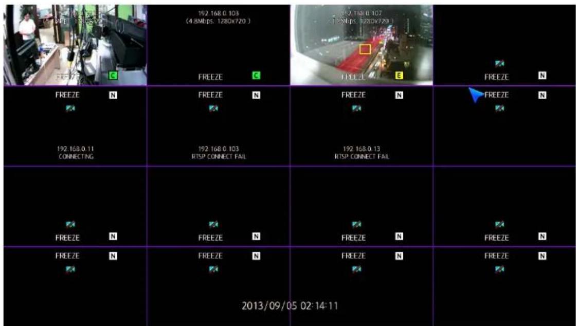
FREEZE OFF : You can release Freeze mode by pressing Freeze Off.

PTZ: Selecting PTZ will bring up PTZ control screen. PTZ can only be controlled by an authorized user. PTZ mode will be activated in the channel you selected by mouse.

ZOOM : This execute digital zoom control screen. Zoom mode will be activated in the channel you selected by mouse.
IP SCAN: You can scan the IP camera currently connected to NVR. The IP camera connected to NVR through peer to peer connection or local / Ethernet port both can be scanned.
IP cameras connected to peer to peer port will be assigned channels automatically. The cameras connected to Ethernet or Local port can be scanned, but not assigned channels automatically. You have to assign by manually.
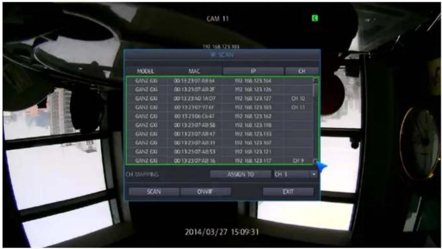
Please refer to IP cam menu for more details.
ALARM RESET: To turn off the buzzer and relay output when "until key" selected in event menu.
ONE CLICK FOCUS: execute the focus adjustment on MFZ lens model.
6. HOW TO CONFIGURE
To view the setup menu in each configuration items, press menu button of toolbar. Following screen will be displayed.

6.1 CONFIGURING CAMERA
To set-up the various camera options.

6.1.1 TITLE
TITLE: Up to 10 characters could be set by using the virtual keyboard.

6.1.2 ADJUST
You can adjust the video attributes such as 'BRIGHTNESS', 'CONTRAST', 'SHARPNESS' and 'SATURATION' by clicking one of the values for the required channel. This feature is only available for the camera connected by "auto mode".

BRIGHTNESS: configure the camera brightness. Value range is 1 \~ 100%.
CONTRAST: configure the camera contrast. Value range is 1 \~ 100%
SHARPNESS: configure the camera sharpness. Value range is 1 \~ 100%
SATURATION: configure the camera saturation. Value range is 1 \~ 100%
If you double-click on the item that want to change. Switch to full screen mode.
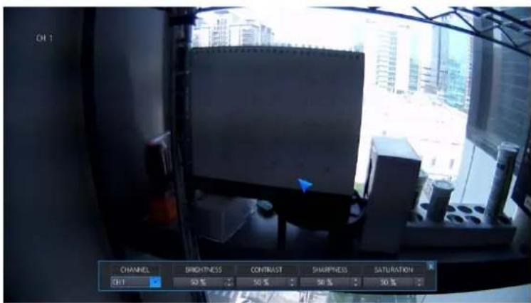
After setting, press the "X (Exit)" button again to switch to the menu.
6.1.3 PTZ
For controlling PTZ by RS-485 port, you need to specify PTZ protocol.

ADDRESS: The unique ID of the PTZ device.
PROTOCOL: The protocol of the PTZ device.
BAUDRATE: The baud rate of the PTZ device.
6.1.4 CAM PORT
This is menu to set up IP camera connected peer to peer port. Before connecting IP camera to NVR, we recommend you to configure IP set up menu, local port set up menu correctly.

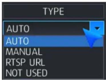
TYPE: You can select connection type AUTO/MANUAL/RTSP
AUTO: Select this mode for peer to peer connection with built-in HUB
√ The Default IP address will be allocated 192.168.172.101 \~ 104 (4ch) / 192.168.172.101 \~ 108 (8 & 16ch) automatically.
√ Keep default value of IP camera in ID, Password, RTSP Port, HTTP port, HTTP type
√ If the ID and password of IP camera is not default value, NVR can't change the configuration of IP camera at "Auto" connection mode. So you need to specify ID and password from "Detail" menu.
MANUAL: Select this mode for 3 ^rd party ONVIF camera or camera is located in the network connected "Ethernet" / "Local" port.
√ Select network port for the camera you want to connect.

The IP range of Local or Ethernet PORT for the connection between IP camera and NVR should be same.
√ You have to use 'Detail menu ... for configuration of IP camera such as port number, ID, password and so on.
RTSP URL: You can use RTSP command to make a connection with IP camera.
√ IP ADDRESS: IP address of IP camera.
√ RTSP PORT: RTSP port number for RTSP transmission.
√ INPUT RTSP URL: Specify the command of RTSP connection. IP address and port number is automatically specified. [example : rtps://192.169.0.101:554/gnz_media/main/]
√ APPLY: Save the configuration.
√ CANCEL: Cancel the configuration.
IP camera configuration cannot be modified if RTSP connection selected.
DETAIL(....): Modify the configuration of the camera if you need.
If the configuration (RTSP port/HTTP port/ HTTP Type / ID / password) of the camera is not default value, you have to modify it. [Supported model]
Set configurations [ONVIF mode]

➢ IP ADDRESS (in manual mode): Input IP address of IP camera.
√ Default(When used to Ethernet port): 4ch 192.168.0.201 \~ 204 / 8& 16ch 192.168.0.201 \~ 208
√ Default(When used to local port): 4ch 192.168.172.101 \~ 104 / 8 & 16ch 192.168.172.101 \~ 108
➢ RTSP PORT (in manual mode): Input RTSP port info.
√ Default: 554
- RTSP port setup value is not matched with IP camera, you'll have the message in the live view "RTSP CONNECT FAIL".
HTTP PORT: Input HTTP port
√ Default : 80
If the HTTP port setting is different from the IP camera, you'll have the message in the live view "HTTP CONNECT FAIL".
HTTP TYPE: Select HTTP type of camera either HTTP or HTTPS
√ Default: HTTP
- USER ID: Input ID of IP camera.
√ Default : root
➢ PASSWORD: Input password of IP camera.
√ Default: pass
You can change the configuration of IP camera only in case that ID/PASSWORD info already configured is correct.
➢ MODEL (in manual mode): User can select the IP camera model which you want to connect.
SCAN: User can scan IP camera currently installed to Local/Ethernet network.
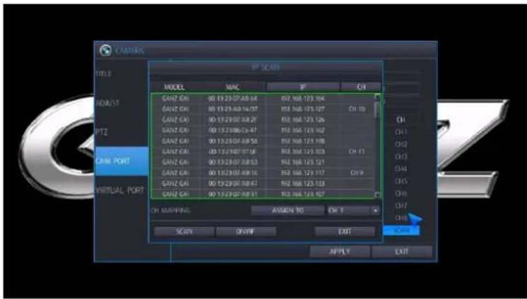
➢ MODEL: The model of searched IP camera.
MAC: MAC address of IP camera.
IP: IP address of IP camera.
CH: The channel information which assigned to NVR.
➢ Assign To: You can assign the camera to preferred channel of NVR.
When you connect IP camera to NVR, be sure between network port (Ethernet or local port) connecting to NVR and IP camera should be same network.
6.1.5 VIRTUAL PORT
This is menu to set up IP camera channel 9\~16 to NVR. Before connecting IP camera to NVR, recommend you to configure IP set up menu, local port set up menu correctly.
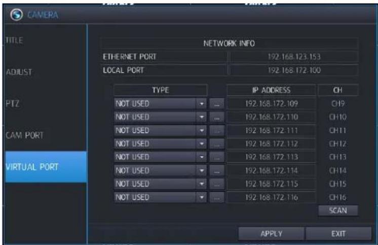
Virtual port menu is same as the cam port menu.
Virtual port menu is not support the "AUTO" mode.
6.2 CONFIGURING DISPLAY
To set-up the various display options.

6.2.1 OSD
Configure camera OSD parameters.
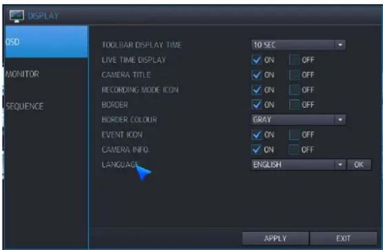
TOOLBAR DISPLAY TIME: set tool bar display time from ALWAYS / 5 SEC /10 SEC / 15 SEC / 20 SEC / 30 SEC / 1 MIN.
LIVE TIME DISPLAY: Select the live time display On / Off.
CAMERA TITLE: Select the camera title display On / Off.
RECORDING MODE ICON: Select to display the recording status icon on the Live View.
BORDER: Determines whether display channel border line in multi-screen display mode.
BORDER COLOUR: If the border is ON, you can select the color.
EVENT ICON: Determines whether the event (Alarm, V-loss) icon is displayed.
CAMERA INFO.: Display camera information (resolution/bit ratite).
LANGUAGE: Select the language for menu.
ENGLISH / KOREAN / GERMAN / POLISH / JAPANESE / FINNISH / RUSSIAN / SPANISH / ITALIAN / FRENCH
6.2.2 MONITOR
NVR's resolution / screen switch can be changed here.

ALARM POP-UP MODE: When you set ON, an alarm input will cause the associated channel to display full screen.
ALARM POP-UP DWELL: Determines how long the full screen popup is displayed after an alarm event.
MOTION POP-UP MODE: When you set to ON, motion detection will cause the associated channel to display full screen.
MOTION POP-UP DWELL: Determines how long the full screen pop-up is displayed after motion detection.
If motion continues, the popup screen is displayed constantly.
VIDEO OUTPUT RESOLUTION (MAIN VIDEO OUTPUT MODE): You can configure video output resolution of main video from 1024x768 / 1280x1024 / 720p / 1080P 30Hz
OK: click OK button to confirm modification works with your monitor. If you cannot get image, please keep wait for 15 seconds. Monitor resolution will be back to previous setting automatically.
Depending on monitor doesn't support HD resolution, then configure VGA resolution on NVR.
In case HD resolution like 720p/1080p connect with VGA cable, when installation, firstly connect VGA cable and power on for NVR.
Factory default resolution is 1024x 768, so you should use monitor supporting at least 1024 x 768.
VGA HORIZONTAL OFFSET: You can change the horizontal position of VGA.
VGA VERTICAL OFFSET: You can change the vertical position of VGA
SD VIDEO OUTPUT: Select the CVBS output mode.
MAIN : Display without GUI the multi-channel display live view of main monitor.
➢ SPOT : Display the live view of spot monitor (1ch sequence).
DEFAULT SPOT CH: When you turn on the NVR, select the default ch to display.
6.2.3 SEQUENCE
Screen auto switch time can be configured here.

SEQUENCE DWELL: Set sequence interval time for main monitor (5/10/15/20/30/40/60 seconds).
SPOT SEQUENCE DWELL: Set sequence interval time for spot monitor (5/10/15/20/30/40/60 seconds).
SPOT SEQUENCE MODE: You can select the sequence mode of spot monitor.
➢ AUTO: keep always sequence operation on spot monitor output.
MANUAL: keep a channel set in the menu.
6.3 CONFIGURING DISK
Recording device related configuration and operation can be executed here

6.3.1 SETUP
You can configure the setting of DISK.

OVERWRITE: If you select "ON", overwrite mode will be activated.
RECORDING TIME LIMIT: The recording data will be deleted after a specific time (12hr - 2 month). If it's set to "OFF", this function will be disabled.
Recording HDD setup: HDD connecting to NVR, can be configured as recording HDD or mirroring HD D, click Red marked HDD and configure operation mode and mark S.M.A.R.T.

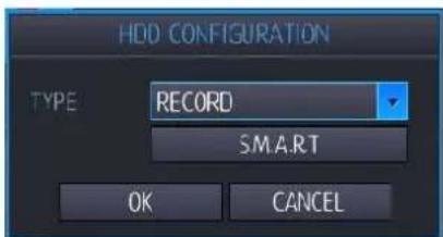
RECORD : You can select HDD as record HDD.
MIRRORING : You can select HDD as mirroring HDD.
S.M.A.R.T: You can view S.M.A.R.T. information of the HDD.

➢ GOOD: It shows current HDD condition is good.
BAD: It shows current HDD condition is bad.
HDD's S.M.A.R.T information would not be supported depending on HDD.
RAID: You can configure the RAID-5 group.
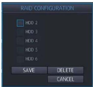
- Minimum three HDDs are required.
All HDD should be the same capacity.
When the configuration is completed, you need to restart the NVR.
6.3.2 FORMAT
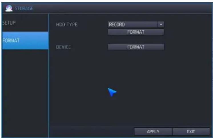
HDD TYPE: You can select HDD Type (RECORD or MIRRORING) to format.
FORMAT: Click this button to execute format HDDs.
- Formatting time would be different depending on recorded capacity in HDD.
Device: Select USB processing
NVR support format function of USB memory stick and external hard drive
FORMAT: Click this button to execute format USB Device..
6.4 CONFIGURING SYSTEM
To set-up the various system options, highlight SYSTEM and press ENTER.

6.4.1 DATE TIME
DATE&TIME: Allows the operator to set or modify the current date & time.
After changing date / time, press (APPLY) button to apply changes.
DATE FORMAT: Select Date display format.
YYYY/MM/DD(Default), MM/DD/YYYY, DD/MM/YYYY
TIME FORMAT: Select Time display format.
24 Hour(Default), AM/PM
NETWORK TIME SERVER SETUP: You can synchronize NVR time to network time sever. It requires internet connection for default server.
Default Server: pool.ntp.org
ADJUST PERIOD (INTERVAL): Interval to synchronize Network Time Server.
Network time server synchronization just starts after NVR configure power on/operation interval setup.
TIME ZONE SETUP: Select the time zone for your local area
D.S.T: When set to ON, the NVR will automatically adjust the time by one hour on the relevant date in spring and autumn
FROM: D.S.T Start time of DST
➢ End : D.S.T End Time of DST
6.4.2 MANAGEMENT
NVR's system information/ firmware upgrade can be processed here.

SYSTEM INFORMATION: Select INFO to display. Following window will be displayed.

F/W VERSION: The firmware version of the NVR.
H/W VERSION: The hardware version of the NVR.
➢ UI VERSION: The UI version of the NVR.
➢ VIDEO OUTPUT: Video output signal mode (NTSC / PAL)
AVAILABLE CAPACITY: Current free space / total capacity of HDD.
➢ AVAILABLE TIME: Remaining recording time and total recording time.
IP ADDRESS 1 : IP address of Ethernet Port
IP ADDRESS 2 : IP address of Local Port
MAC address 1 : MAC address of Ethernet port
MAC address 2 : MAC address of local port.
➢ DDNS SERVER ADDRESS: If DDNS is enabled, the server name will be shown.
➢ DVR SERVICE PORT: port number for NVR network operation
WEB SERVER PORT: The port number that the NVR uses to support remote connections.
➢ FAN STATUS: FAN Speed of NVR (RPM).
TEMPERATURE: Internal temperature of NVR (°C/°F).
➢ HDD NUMBER: HDD information installed.
SYSTEM NAME: Up to 15 characters can be defined. Notification emails will have the system name for identification.
F/W UPGRADE: Use this button to upgrade Firmware.
fiCopy new Firmware files in "dvr" folder of USB memory stick.
Connect USB memory to NVR, then click F/W UPGRADE button.
FACTORY DEFAULT: Set all settings to factory default.
SYSTEM DATA: You can save/load System settings to/from USB memory stick.
VIDEO OUTPUT: You can select Video Signal type for CVBS output.
If you change the video signal, system rebooting is required.
AUTO LOGIN (PASSWORD): Selects if a password is required 'ON / OFF'.
Note) Password must be selected to 'ON' if USER MANGEMENT options are required.
MAKE RESCUE DISK: You can make the recovery file when NVR has problem to start up.
How to Create a Recovery Disc
√ Plug the prepared USB thumb drive in the USB port of NVR.
√ Click the 'create'
How to recover
√ Disconnect the HDD disk of NVR
√ Plug the prepared USB thumb drive in the USB port of NVR.
√ Turn on the NVR. NVR will load the system from recovery disk.
6.4.3 SOUND

LIVE AUDIO: If you select "on", Audio output is available at live mode.
DEFAULT AUDIO CHANNEL: Specify which channel of the AUDIO INPUTS is routed to the AUDIO OUTPUT when the NVR is in multi-screen mode.
KEYPRESS: This setting will turn the IR Remote confirmation beep on or off.
6.5 CONFIGURING EVENT / SENSOR
You can configure Event activation like Sensor Input / Sensor Output / Buzzer Out / E-Mail / Push Alarm.

6.5.1 SENSOR INPUT

You can configure Alarm input.
OPERATION: You can configure Enable/Disable Sensor input.
TYPE: If the operation is enabled, you can select sensor type.
N/O: Keep Open when Sensor is on normal state.
N/C: Keep Close when Sensor is on normal state.
TEXT: You can configure the title for each sensor input.
6.5.2 ALARM OUTPUT SETUP
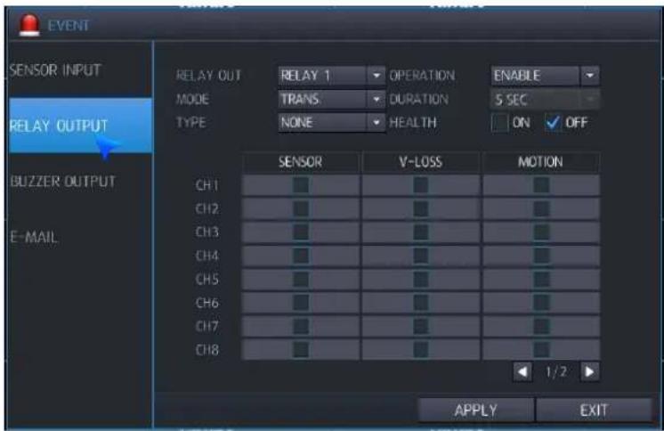
You can cofniture activation of Relay output.
RELAY OUT : You can select Relay for the operation.
4ch NVR : 1 relay, 8/16ch NVR: 2 relay
OPERATION: You can configure Enable/Disable Relay output.
MODE: You can configure operation type of Relay output.
TRANSPARENT: Keep Relay output until event triggering stopped.
LATCHED: Keep relay output as long as duration specified.
DURATION: If the alarm output mode is configured as Latched. You can configure duration for relay output.
TYPE : Define the signal type of Relay output
N/O (Active Low): When event triggered, the relay will go to 'Close' state from the 'Open'.
N/C(Active High): When event triggered, the relay will go to 'Open' state from the 'Close'
HEALTH CHECK: If you select "ON", when NVR system Event is triggered, relay output will be activated. (booting / Fan Error / HDD Error...)
SENSOR: When sensor input, relay output will be activated.
VIDEO LOSS: When video loss occurred, replay output will be activated.
MOTION: When motion triggered, replay output will be activated.
6.5.3 BUZZER OUTPUT SETUP
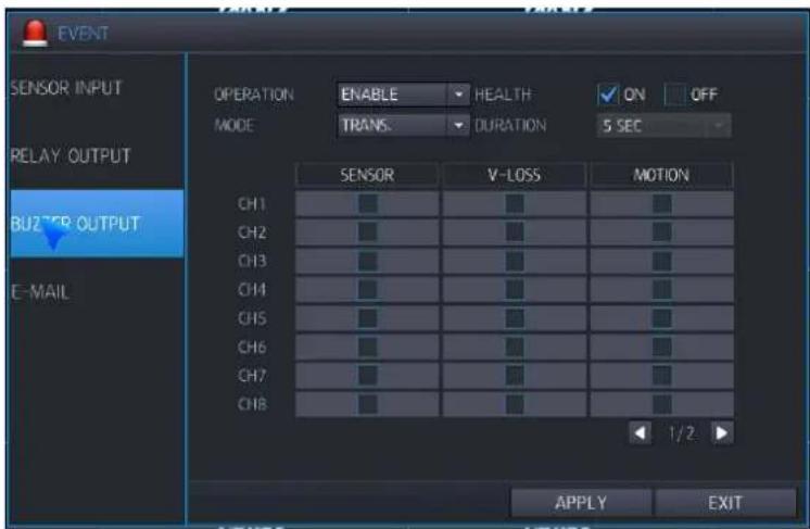
You can configure Buzzer output when event triggered.
OPERATION: You can configure Enable/Disable of the Buzzer.
HEALTH CHECK: If you select "ON", when NVR system Event is triggered, relay output will be activated. (booting / Fan Error / HDD Error...)
MODE: You can configure operation mode of Buzzer output.
TRANSPARENT: Keep buzzer output until event operation is stopped.
LATCHED: Keep buzzer output as long as duration specified.
DURATION: You can configure duration for buzzer output at latched mode.
SENSOR: When sensor input, buzzer output will be activated.
VIDEO LOSS: When video loss occurred, buzzer output will be activated.
MOTION: When motion triggered, buzzer output will be activated.
6.5.4 E-MAIL SETUP

You can confiture E-mail notification when event triggered like follows.
NOTIFICATION: If you select "ON", E-mail will be sent when event triggered.
SETUP: If you select "ON", E-mail will be sent when configuration is changed.
HEALTH CHECK: If you select "ON", E-mail will be sent when NVR system Event is triggered.
BOOT: If you select "ON", E-mail will be sent when NVR boot-up.
SENSOR : E-mail will be sent, when sensor is triggered.
+ VIDEO LOSS : Email will be sent, when video loss occurred.
MOTION : Email will be sent, when motion triggered.
FREQUENCY: You can configure E-Mail notification period.
6.6 CONFIGURING USER
To set-up the User Authority options.
6.6.1 USER REGISTER
By default, the NVR is configured with a USER ID of ADMIN belonging to the ADMIN group and with a password of 1234.
Using this, max 10 new user accounts can be registered and configure authority separately.
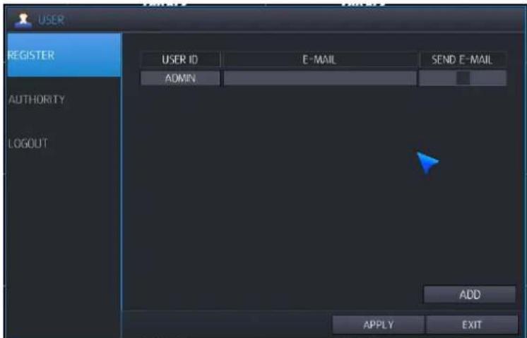
To create new user, click "ADD" button.
To modify user details, double click registered user on the menu.
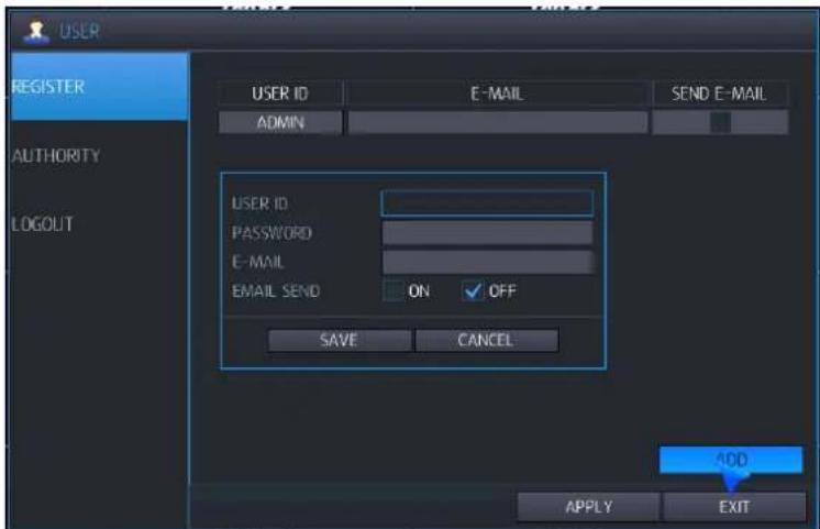
- USER ID: Edit the user ID using the virtual keyboard. (Max 10 characters).
PASSWORD: Change the password using the virtual keyboard. (Max 8 characters)
Note: To delete the existing password, use the "Clear" on the virtual keyboard.
E-MAIL: Enter the user's email address if email notifications are required.
E-MAIL SEND: Enable or disable email notification for the particular user.
NOTE) Maximum 10 users can be registered.
NOTE) default ADMIN user could not be deleted.
6.6.2 USER AUTHORITY
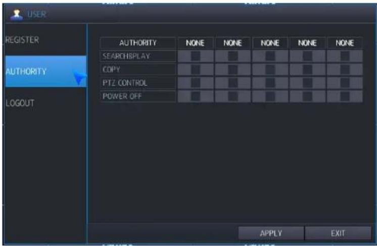
User authority (except ADMIN) can be selected for each user.
Search & Play : Right to enter Search Menu/ Instant Playback.
COPY : Right to enter backup menu.
PTZ CONTROL: Right enter PTZ control menu.
Power OFF : Right to shut down NVR.
6.6.3 LOG-OUT
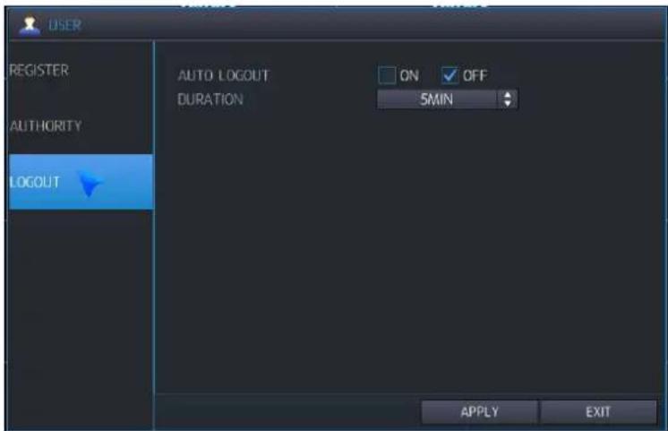
AUTO LOGOUT: Selects auto log-out ON or OFF.
DURATION: If auto log is set to ON, select duration to log-out. (in 1 - 10 Min)
6.7 CONFIGURING RECORD
To set-up the various recording options, highlight RECORD.

6.7.1 MAIN STREAM
Main stream configuration is set up here. The stream configuration can be setup in only "AUTO" mode (peer to peer mode).

In case, "Manual"/"RTSP" mode, stream configuration need to be setup in camera interface directly by PC.
SIZE: You can select what resolution of video will be recorded as follows.
ALL: Set the resolution for all channels
Note) The resolution setting value is represented with the ratio of the connected IP camera's recording resolution because there could be mixed connection of IP camera inputs.
FPS: You can select recording frame rate as 0 / 1 / 2 / 4 / 5 / 8 / 10 / 15 / 30 at NTSC mode or 0 / 1 / 2 / 4 / 5 / 7 / 10 / 13 / 25 at PAL mode.
QUALITY : You can select recording video quality as 5 levels like; Low / Standard / High / Highest / Super
| Low | Standard | High | Highest | Super | |
| D1 | 512Kbps | 768Kbps | 1Mbps | 1.5Mbps | 2Mbps |
| 720p | 2Mbps | 2.5Mbps | 3Mbps | 3.5Mbps | 4Mbps |
| 1080p | 2.5Mbps | 3.5Mbps | 4Mbps | 5Mbps | 6Mbps |
According to H.264 profile format, maximum bit rate is recommended.
High profile: 4Mbps/ Main profile: 4M bps, Baseline profile: 6M bps.
VCA: You can choose the VCA Operation.
6.7.2 SUB STREAM
Sub stream configuration is set up here. The stream configuration can be setup in only "AUTO" mode (peer to peer mode).

In case, "Manual"/"RTSP" mode, stream configuration need to be setup in camera interface directly by PC.
SIZE: You can select what resolution of video will be recorded as follows.
➢ Resolution : D1 / CIF
ALL: Set the resolution for all channels
Note) The resolution setting value is represented with the ratio of the connected IP camera's recording resolution because there could be mixed connection of IP camera inputs.
FPS: You can select recording frame rate as 0 / 1 / 2 / 4 / 5 / 8 / 10 / 15 / 30 at NTSC mode or 0 / 1 / 2 / 4 / 5 / 7 / 10 / 13 / 25 at PAL mode.
QUALITY : You can select recording video quality as 5 levels like; Low / Standard / High / Highest / Super
| Standard Highest Super | |||
| CIF | 256Kbps | 512Kbps | 1024Kbps |
| D1 | 256Kbps | 512Kbps | 1024Kbps |
6.7.3 SCHEDULE

You can configure schedule recording mode as Daily / Weekly.
Daily: set up one schedule and apply to every day.
Weekly: set up 7 schedules from Monday to Sunday, and use it for every week.
Select daily or weekly in "OPTION" menu.
TYPE: You can select recording mode out of total 8 modes. Refer to the below picture

No record.
Continuous record
➢ Motion record. (Motion &VCA when VCA enabled)
➢ Alarm record
➢ Motion & Continuous record (Motion & VA & Continuous when VCA enabled)
➢ Continuous & Alarm record
➢ Motion & Alarm record (Motion & VCA & Alarm when VCA enabled)
Continuous & Motion & Alarm record (Continuous & Motion & VCA & Alarm when VCA enabled)
Note) You can enable Day or Week recording mode at the configuration of 'OPTION' menu
Note) you can configure schedule time table by drag using left mouse click.
6.7.4 OPTION

SCHEDULE MODE: Either DAILY (one schedule will apply to every day of the week) or WEEKLY (each day of the week has its own schedule).
DAYLY: You can configure the recording type by a hour and by a channel. This mode is for the demand that all days have the same recording schedule regardless of the day of the week.
WEEKLY: In this mode, you can configure the recording type by a hour, by a channel and by the day of the week. This mode is suitable for the user who wants to configure the separate schedule according to the day of the week.
PRE-EVENT RECORDING TIME: When the NVR is event recording mode, this setting determines the amount of footage that is always recorded before an event occurs (VA, motion detection, alarm input etc.)
POST-EVENT RECORDING TIME: You can configure how long the system keep event recording after event triggered.
Event triggered repeatedly before finishing recording, post event recording can be recorded after last event.
AUDIO RECORDING: Select channel for audio recording.

LIVE STREAM: You can select either Main or Sub stream for live display.
RECORD STREAM: You can select either Main or Sub stream for recording.
Mirroring: You can enable mirroring recording mode or not.
ON: Select mirroring record and record as per mirroring way.
√ EVENT: Just event data will be recorded to mirroring HDD.
√ ALL: Same data will be recorded to mirroring HDD same as current recording data.
OFF: Mirroring record off
SELECT CHANNEL FOR MIRRORING: You can check which channel will be recorded to mirroring HDD.
All: all channel with mirroring record.
➢ Channel 1\~16: selected channel record with mirroring.

6.8 CONFIGURING NETWORK
To set-up the Network options, highlight NETWORK and press ENTER. Configure all the menu of network.

6.8.1 ETHERNET PORT
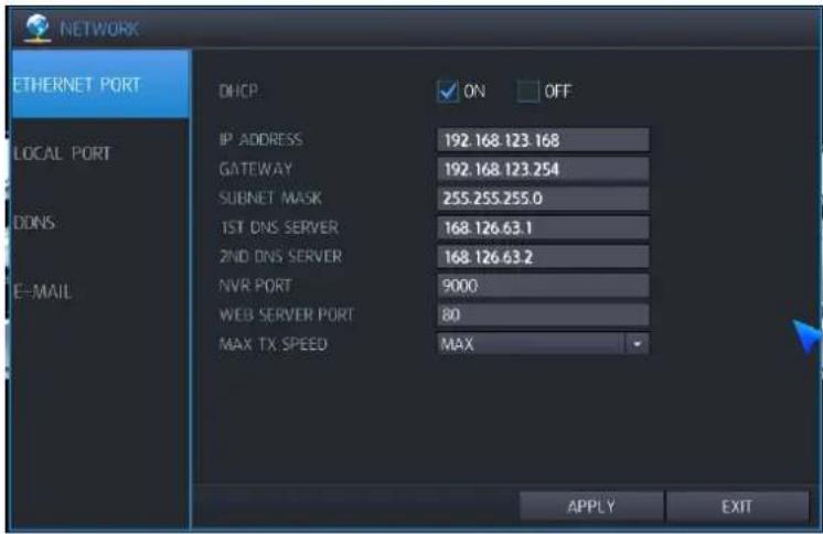
IP set up menu for Ethernet port. It require to setup when connect IP cameras on Ethernet port or you access NVR from client SW.
DHCP: When selected the NVR will obtain an Ethernet IP address automatically if connected to a DHCP server or router.
IP ADDRESS: Set IP address when DHCP is not being used.
GATEWAY: Set Gateway when DHCP is not being used.
SUBNET MASK: Set subnet mask when DHCP is not being used.
1ST DNS SERVER: Set the 1st DNS server address when DHCP is not being used.
2ND DNS SERVER: Set the 2nd DNS server address when DHCP is not being used.
NVR PORT: The port number that the NVR uses to support to the remote software.
WEB SERVER PORT: The port number that the NVR uses to support remote connection from Internet Explorer or other web browsers.
Using Internet router, If connect more than one NVR, you should configure service port and web service port differently.
MAX TX SPEED: Specifies the maximum bandwidth that the NVR can use during a remote connection.
Note) Both NVR & WEB SERVER PORT will need a firewall rule creating for remote Connection
Note) uPNP (Auto Port Forwarding) is activated always background.
Note) uPNP function for automatic forwarding setup would not compatible depending on router and hub, in this case user should configure port forwarding properly.
6.8.2 LOCAL PORT
IP setup menu for Local port.
In AUTO mode, NVR will assign IP address based on local port setting to IP camera automatically.
In Manual/RTSP mode, you need to assign same segment of IP address to the camera manually.

IP ADDRESS: Set IP address for Local port. Default value is 192.168.172.100
GATEWAY: Set Gateway for Local port.
SUBNET MASK: N/A grayed out
6.8.3 DDNS

DDNS: When enabled the NVR can be accessed through a dynamic DNS server. Commonly used if a broadband connection does not have a static IP address.
DDNS SERVER: DDNS server Name.
AUTO DDNS: When set ON in auto DDNS menu, be automatically register DDNS server.

AUTO DDNS NAME: DDNS name registered on the server is displayed.
6.8.4 E-MAIL

USE DEFAULT SERVER: Selects ON or OFF. If you make Default sever as ON, mail will be sent by default mail server displayed.
SERVER: The SMTP outbound email server that should be used to send email notifications.
PORT: The outbound email port number.
SECURITY: Set to OFF if the SERVER does not require a username and password to connect.
+ USER: Enter a username to identify the NVR in email messages.
PASSWORD: If SECURITY is set to ON, enter the password here.
FROM: Input an email address or text.
TEST E-MAIL: Specify destination address for test e-mail.
Test: Send test mail to destination address specified.
To use email function, you have to configure 'user' menu and 'event/sensor' menu too.
7. REMOTE
7.1 WEB SERVER
NVR prepares the web server internally. This server consists of two services. One is for the remote configuration of NVR setup and the other is for the client viewer based on the Active-X. Using the remote configuration, you can configure all feature sets of NVR. And the live preview, search and PTZ control can be served by the 'WebViewer'.
The table below shows the recommended PC specification for the proper operation.
[Recommended Specification of PC]
| Recommended | |
| Operating System Windows | 7 |
| CPU Core i5 @3.3GHz or Higher | |
| Memory | 2 |
| Video Card Memory 512MB | |
| HDD Capacity 2GB | |
| VGA Resolution 1920x1080x32 | |
| Direct-X | DirectX |
| Network | Etheret |
7.1.1 CONNECT TO WEB SERVER
Enter the IP address of NVR into the ULR bar referring to the below picture.

http://192.168.123.54:80
NOTE) You can know the IP address of NVR from the 'INFO' section under the OPERATION SETUP of NVR menu. If the local IP which starts with '192.168.xxx.xxx' is used in the NVR, you have to set the 'Port Forwarding' properly in your router. The port number to set can be get from 'NVR PORT' in the NETWORK SETUP. If your router supports the 'uPNP' feature, there is no need to set 'Port Forwarding' manually because the NVR supports the 'Auto Port Forwarding' function using the 'uPNP' protocol. (Some routers can make the compatibility issues to the uPNP protocol of NVR)
NOTE) If the access to the web server can't be established after setting the 'Port Forwarding', you may need to check the firewall of router and your PC. The port used in the NVR should be allowed to access by the firewall.
[The initial screen of Web Server]
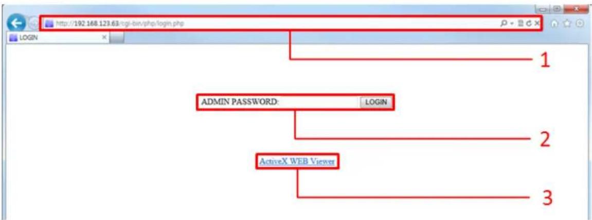
1: Enter the IP address of your NVR. If you don't use the default port number of HTTP, 80, you may add the port number following the IP address. Ex. http://192.168.123.63:8080
2: Input the administrator's password beside of the 'ADMIN PASSWORD'. Only administrator can log in for the NVR configuration. Clicking the 'LOGIN' button will guide you to the NVR configuration pages.
3: ActiveX based Web Viewer: Clicking the link execute the 'ActiveX WEB Viewer' or initiate the installation of ActiveX plugin.
In the web configuration page, you can set the NVR operations remotely.
Tested Web Browser List
♦ Microsoft Internet Explorer®
- Mozilla Firefox®
Google Chrome Browser®
♦ Opera Browser®
Apple Safari®
Features
Configuring the NVR setup remotely
After giving the ADMIN's password and clicking 'LOGIN', you can move into the page where you can configure the setup menu of NVR.
ADMIN PASSWORD: •••• LOGIN
NOTE) Default Password for ADMIN: 1234
NOTE) Only ADMIN account can access the menu configuration pages.
NOTE) When no operation more than 5 minutes is, the configuration page will be logged out automatically.
7.1.2.1 Initial Page of Web Configuration

flowchart
graph TD
    A["LOG OUT"] --> B["CAMERA"]
    B --> C["DISPLAY"]
    C --> D["SYSTEM"]
    D --> E["USER"]
    E --> F["NETWORK"]
    F --> G["EVENT/SENSOR"]
    G --> H["DISK"]
    H --> I["RECORD"]
    I --> J["3"]
    K["SETUP"] --> L["TITLE"]
    L --> M["CH 1"]
    L --> N["CH 2"]
    L --> O["CH 3"]
    L --> P["CH 4"]
    Q["CANCEL"] --> R["6"]
    S["APPLY"] --> R
    T["Ver 1.0.0"] --> U["2"]
1: log out from the configuration page
2: version number of this web configuration
3: Top menu of NVR
4: Sub menu of NVR
5: Setting or Information section
6: Cancling or applying the modification
CANCEL : Ignore any modification and the modification is recovered to the previous setting
APPLY: the modified setting is applied to NVR and saved
In order to apply or save, you should click the 'APPLY' button. Otherwise all the changes will be lost.
For the detail description of the NVR configuration, please refer the '5.HOW TO CONFIGURE' section of this manual. Clicking the following link will guide you to the proper section which explains each setup.
CAMERA
DISPLAY
SYSTEM
USER
NETWORK
EVENT/SENSOR
DISK
RECORD
Search, Playback & Copy functions are not supported from the web server. To user these, please use the 'Web Viewer' instead.
7.1.3 WEB VIEWER (Active-X)
Thought the 'Web Viewer', you can see the live preview video, search and playback of recordings in the NVR and copy the recordings out from the NVR.
Tested Web Browser
♦ Microsoft Internet Explorer®
♦ Mozilla Firefox®
Google Chrome Browser®
Features
This 'Web Viewer' is based on the ActiveX
Monitoring the live preview videos from the NVR.
Searching & Playback of the recordings in the NVR
Copy the recording data in the NVR to the PC remotely
PTZ camera control remotely
7.1.3.1 Installation and Execution
[Microsoft IE]
Click the 'ActiveX WEB Viewer' initiate the installation of the 'Web Viewer' if not installed previously. If the 'Web Viewer' is installed already in your IE browser, plug-in will start without installing ActiveX.
ActiveX WEB Viewer
NOTE) First execution of 'Web Viewer' will install the application first.
NOTE) If new updated version of 'Web Viewer' is found, updating starts automatically before execution.
[Google Chrome]
In order to execute the ActiveX plugin, you have to install the 'IE TAB' from Google web store referring the following steps.
Execute the Chrome browser
Goto the https://chrome.google.com/webstore/category/home
Enter the word 'IE TAB' into the 'Search the store' box and press enter.

'Searching' shows the results such as below.

Click the 'ADD TO CHROME' and then you can see the IE symbol on the right side of URL Bar

There are two ways to execute the 'Web Viewer' from the Chrome.
- Click the ICON() on the right side of URL bar. It opens new URL bar to get the URL. Entering the required IP address of NVR will connect the web server.
- Just entering the IP address of NVR into the URL bar of Chrome and press enter
[Mozilla Firefox]
In order to execute the ActiveX plugin, you have to install the 'IE TAB' from the add-on page of Firefox referring the following steps
Execute the FireFox browser
Go to the https://addons.mozilla.org/en-US/firefox/addon/ie-tab. And then the following page will show the way to install the 'IE TAB'.
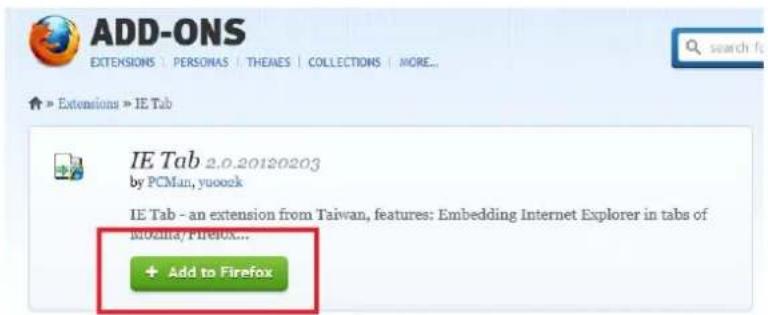
Click the 'Add to Firefox' will enable supporting Active-X plugin.
Way to execute the 'Web Viewer' from the Firefox
Enter the IP of NVR into the URL bar of Firefox.
Right-click the link 'AcitveX WEB Viewer' will show the pop-up menu such as below.

Select the 'Open Link in IE TAB'. ActiveX
First execution will install the ActiveX plug-in. And the application will be executed if installed already.
7.1.3.2 Initial Screen of Web Viewer
Executing the 'Web Viewer' opens the application separated from the web browser and show the login window such as below picture.
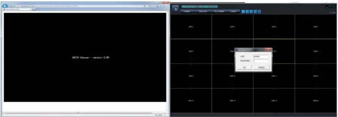
7.1.3.3 Log In
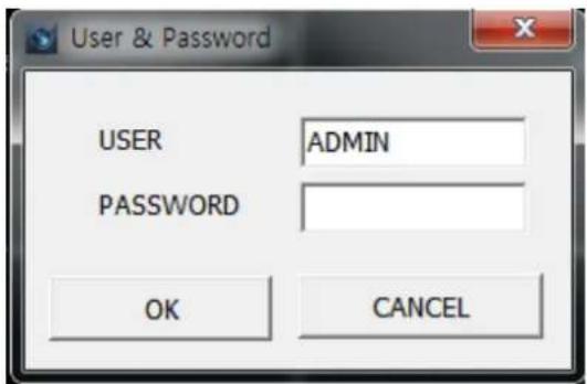

: Enter the USER name of NVR registered in the NVR
: Enter the password for the selected user.
The user authority and allowed functions, live preview, search & playback, PTZ control and etc., are controlled by the setting USER AUTHORITY setting of NVR setup
7.1.3.4 Live Preview
After login, the live preview screen will be shown as below.
Features
4 User log-in/out feature (CONNECT)
Monitoring the live preview
Snapshot and save the preview video as JPEG
(Admin Only) Control the resolution and quality for transferred video stream directly

The yellow rectangle around video shows the currently selected camera
1 : IP address of connected NVR
2 : display split mode selection

3 : WEB Viewer Minimize/Maximize/Close
4 : Reconnect / Live&Search / Full Screen

5: Date & Time Information
6 : Channel Title and the resolution of the transferred video
7.1.3.5 JPEG Snapshot/ PTZ control / Video Configuration /Live Audio
In the Web Viewer, you can save the video as JPEG file, control the PTZ of camera and hear the audio from the NVR. And especially, you can configure the transferred video directly from the viewer.
The right-click on the video window shows the pop-up menu such as following picture.

: Save the current video of the selected channel with the yellow border into the PC as a JPEG file.
: Select stream for Live view (Main or Sub stream)
LIVE AUDIO SEND : This function is 'two way audio function'. If you press the 'live audio send' send audio from the PC to NVR.
: Open the PTZ control panel
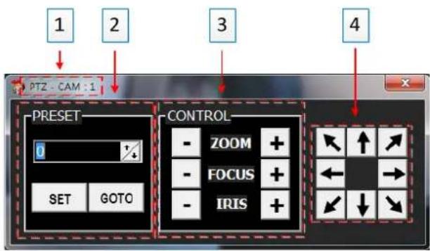
1: Camera Channel number which is currently selected.
2: PRESET OPERATION OF PTZ
3: ZOOM/FOCUS/IRIS CONTROL
4: DIRECTION CONTROL (PAN & TILT)
7.1.3.6 Search & Playback
LIVE / PLAY
Entering to the search & playback window or Returning to the live preview
Features
User log-in/out feature (CONNECT)
Switching between the live preview and the search & playback
Search & Playback
Copy the recordings in the NVR to the PC remotely

1: Show the IP address of NVR currently connected
2: Split mode selection.
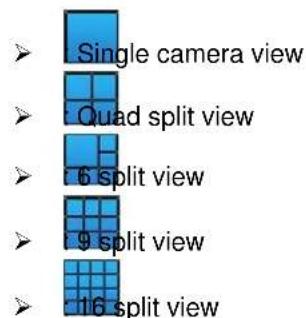
3: Playback speed control

|| : Pause
: Forward Normal Speed
: Forward Slow
: Forward Fast
Steps for fast playback : x2, x4, x8, x16, x30, x60, x120 Steps for slow playback : 1/2, 1/4, 1/8, 1/16, 1/30, 1/60, 1/120
4: Fast Playback Speed & Direction Control Bar
➢ Mouse wheel up: faster in forward direction
➢ Mouse wheel down: reversely faster
➢ Center click: normal speed playback
Click on the right half of bar : faster in forward direction
➢ Click on the left half of bar: reversely faster
➢ 7 level speed control for each direction
5: View window control
minimize the window
:Maximize the window
: Exit the 'Web Viewer'
6: Reconnect/Live&Search/Full Screen
CONNECT
Log out and Reconnect
LIVE / PLAY : Switching between the live preview and the search & playback
FUI SCREEN
Full screen video view. Press 'ESC' to return to the window
7: Calendar Panel: show the selected date for search. The green color indicates that the recording data exist. Click the date will trigger the search for the selected day. The search result is displayed on the time selection table 10.
8 : Copy the recorded video in the NVR to the PC
TAG name: Folder name where the copied AVI file to be saved.
➢ Channel: Choose the channel required to be copied

From: The start time of the recording data to be copied
To: The end time of the recording data to be copied
➢ Copy Start: executing the copy operation
TAG name and Channel have to be defined to proceeding the copy.
9: Choose search type between 'EVENT' and 'TIME'. The time selection table tagged in the above picture is used for one of this two search type.
ch mode to 'Time Search'.
| HCLB | 0 | 1 | 2 | 3 | 4 | 5 | 6 | 7 | 8 | 9 | 10 | 11 | 12 | 13 | 14 | 15 | 16 | 17 | 18 | 19 | 20 | 21 | 22 | 23 | |||||||||||||||||||||||||||||||||||||||||||
| MNI | 0 | 1 | 2 | 3 | 4 | 5 | 6 | 7 | 8 | 9 | 10 | 11 | 12 | 13 | 14 | 15 | 16 | 17 | 18 | 19 | 20 | 21 | 22 | 23 | 24 | 25 | 26 | 27 | 28 | 29 | 30 | 31 | 32 | 33 | 34 | 35 | 36 | 37 | 38 | 39 | 40 | 41 | 42 | 43 | 44 | 45 | 46 | 47 | 48 | 49 | 50 | ||||||||||||||||
| 1-4 | |||||||||||||||||||||||||||||||||||||||||||||||||||||||||||||||||||
| 1-5 | |||||||||||||||||||||||||||||||||||||||||||||||||||||||||||||||||||
| 9-12 | |||||||||||||||||||||||||||||||||||||||||||||||||||||||||||||||||||
| 13-26 | |||||||||||||||||||||||||||||||||||||||||||||||||||||||||||||||||||
| EC | 0 | 1 | 2 | 3 | 4 | 5 | 6 | 7 | 8 | 9 | 10 | 11 | 12 | 13 | 14 | 15 | 16 | 17 | 18 | 19 | 20 | 21 | 22 | 23 | 24 | 25 | 26 | 27 | 28 | 29 | 30 | 31 | 32 | 33 | 34 | 35 | [36] [37] [38] [39] [40] [41] [42] [43] [44] [45] [46] [47] [48] [49] [50] [51] [52] [53] [54] [55] [56] [57] [58] [59] | ||||||||||||||||||||||||||||||
Yellow colored cell indicates the currently selected hour and minute.
Green colored cell means that there is the recording data by the continuous recording.
➢ Red colored cell means that there is the event recording data.
Click or double-click on the cell in the minutes bar will start the playback from the selected time.

COPY Start Time
COPY End Time
Event Search
Right click on the minute bar will show the pop-up menu such as the left pictures.
: Taking the COPY START TIME' from the selected time cell and input it into the 'From' of COPY control panel.
: Taking the 'COPY END TIME' from the selected time cell and input it into the 'To' of COPY control panel.
➢ : Taking the time for 'EVENT SEARCH start time'.
Selection the second by clicking on the 'second' bar will move the second of playback video to the selected second. This is only available during the playback on-going.
Each cells in the time selection table indicates whether the recording data exists or not for that time and channel.

rch mode to 'EVENT Search'.
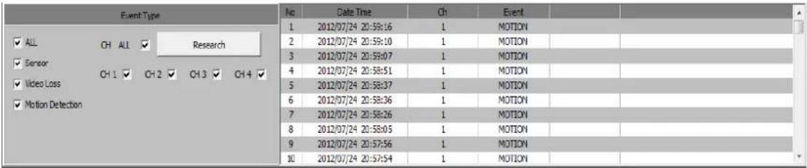
Event Type(Search Condition)
√ All: For all kinds of recording event
√ Sensor: sensor input event
√ Video Loss: lost video event
➢ Motion Detection : motion detection event
▶ CH ALL: Searching for all channels
CH1/CH2/CH3/CH4: choosing the channel to be searched
➢ Research: execute the event search again
10: Time selection & recording indication table / Event search result window


11: display the playback video as a result of searching.
12: show the current playback mode, speed and direction.
7.2 Android Viewer / iOS Viewer
PocketViewer is the name of smart phone viewer for Android
iPocketViewer is the name of smart phone viewer for iOS.
And you can also access to NVR system through 3G/4G phone or Wi-Fi connection.
Main feature
Live View
Full-Screen
Multi Screen Display (4 channel split)
PTZ Control (Pan-Tilt, Zoom, Preset configure and Move)
Live Zoom & Web Menu connection of NVR will be supported through upgraded version.
7.2.1 How to use

If you start PocketViewer/iPocketViewer, you will see the above screen.
Quick Connect : If don't want to save the NVR info to mobile phone, just for one time connection usage.
NVR List : If you want to save the NVR info to mobile phone and control the list of NVR.
7.2.1.1 Quick Connect

If you press Quick Connect button, the above image will be displayed.
NVR Address : You need to input IP Address
Port Number : You need to input NVR port number that you configured at Network menu at NVR.
User ID : You need to input ID that you configured in NVR. (default password of Admin is 1234)
Password : You need to input password ( default password of Admin is 1234)
Connect : You can connect to NVR to view the video pressing Connect button.
Cancel : Close Quick Connect.
7.2.1.2 NVR LIST
If you press NVR list button, following window will be displayed.

New : You can create new NVR will be added to List.
Edit: You can edit list currently stored.
Delete : You can delete list currently stored.
Close: You can close NVR list menu
Connect : You can connect one of List already stored.
Menu : You can connect to Web menu of NVR ( it will be supported in next firmware) after selection one of NVR in the List.
7.2.1.3 How to add NVR to the List
If you press New button, following window will be displayed.

NVR Name : You can name newly added NVR to the List .
NVR IP/DDNS : You can input IP address and DDNS info of NVR.
Port Number : You can input NVR port number.
HTTP Port : You can input HTTP port info of NVR that you configured at NVR network menu.
Note) this menu is for connection with Web Menu of NVR. Which will be supported in upgraded version
User ID : You can input ID that is configured at NVR menu.
Password : You can input password that is configured at NVR menu.
Save : You can store the info that you input pressing Save button.
Cancel : Close adding List
7.2.1.4 How to connect

You can select one of list to make a connection to NVR that you what to view.
7.3 DDNS SERVER
You can get Domain Name Service through DDNS server.
7.3.1 HOW TO REGISTER
You need to input http://dynamicmv.com at URL in Web Brower. You can view following image from DDNS server.

ANDROID VIEWER: You can download Android Viewer ( iPocketViewer) . Android Viewer : Android Viewer
DDNS SERVER: If you press DDNS server button, you will be moved to DDNS server page.
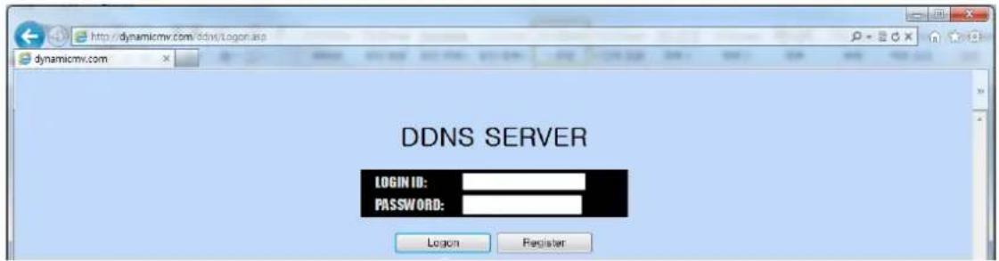
LOGIN ID: Input USER ID.
PASSWORD: Input Password.
Logon: Press Log-in button to log-in
Register: You can create user account.
7.3.2 REGISTER
You can create user account by using register menu.

LOGIN ID : Create ID.
PASSWORD : Create Password..
CONFIRM PASSWORD: Input password again to confirm the password.
7.3.3 Input NVR information.
You need to register domain name to get the service and input MAC address into DDNS server.

1 : List number of registered NVR
2: Mac address of registered NVR
3 : Domain name of registered NVR.
4 : IP address of registered NVR.
5: latest time that NVR sent the info to DDNS server.
6: Update of Last Update
7 : Delete of Domain name registered in DDNS server.
8 : Input Mac Address of NVR that you want to register newly into DDNS server.
9 : Input Domain name of NVR that you want to register newly into DDNS server.
The Domain name type is "user.ns.dynamicmv.com".
ADD : You can register NVR to the DDNS server pressing ADD button.
LIST : The NVR list registered will be displayed.
LOGOUT : User can log out
Note) It will take around 10 to 15 minutes to confirm the registration at the Server.
7.4 DVR MANAGER
DVR MANAGER is a 'Remote Client DVR Viewer' which can provide the functions such as 'Monitoring the live video', 'Search & Playback for the Recorded Video in NVR' and 'Download the Recorded Video in NVR(Remote COPY).
The following table shows the PC requirement for this application S/W.
[Minimum & Recommended Specification of PC]
| Recommended | |
| Operating System Windows | 7 |
| CPU Core i5 @3.3GHz or Higher | |
| Memory | 2 |
| Video Card Memory 512MB | |
| HDD Capacity 2GB | |
| VGA Resolution 1920x1080x32 | |
| Direct-X | DirectX |
| Network | Ethernet |
GB
9.0c 10/100B-TX
7.4.1 INSTALLATION
You can install the 'NVR Manager' using the 'setup' program which is provided in the bundle CD. Executing the 'NVRManager_setup.exe' in the NVR Manager folder will guide you to install this.

: Setup program of DVR Manager

: Introduction of Setup

: Specify the folder location for installation.
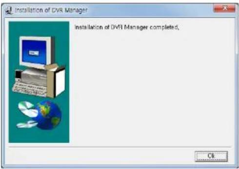
: Complete Message Window
7.4.2 EXECUTION
The shortcut of 'DVR Manager' is created after the successful installation. Clicking this icon executes the DVR Manager.

DVR Manager
: Shortcut and icon of DVR Manager
7.4.3 LIVE VIDEO MONITORING
The initial window of DVR Manager is composed of the picture below.

1 : CONNECTION MANAGER: for registering or deleting the NVR to/from the NVR List.
2 :FULL SCREEN : Fill and fit only the video windows into the PC monitor.
3:CONFIG:

FOLDER SELECT: Choose or make the folder for the data which is copied out from the NVR remotely.
➢ SAVE: Apply and save the current modification.
➢ CLOSE: exit the 'Config' pop-up.
4 : SPLIT MODE SELECTION: choose the number of cameras which will be shown in the live preview window.
1 / 4 / 9 / 16 / 25 / 36 / 49 / 64
5 : Minimize/Maximize/Close NVR Manager
minimize the window
: Maximize the window
: Exit the 'NVR Manager
6 : Live View Window : show the live preview video of the connected NVR.
7 : NVR List Window : list the registered NVRs and indicate the connection status. When the NVR is linked, the cameras connected on that NVR are listed under the NVR.
8 : NVR Information : Show some information of NVR selected.
9 :Version: the version number of NVR Manager
7.4.4 CONNECTION MANAGER
This provides the way to register the NVRs into the NVR list, remove the NVR from the NVR list and editing the NVR connection information.

DVR Name: The name which you give to the NVR which has the following connection information.
DVR Address : specify the IP address of the NVR
DVR Port: the port number for NVR connection. The value should be same as the one specified port number of your NVR.
↓ USER : user ID to be used in the login
+ PASSWORD: password for the selected user.
User name and password is case-sensitive.
DVR SCAN: scan the local network and show the detected NVRs in the list.

MAC Address : show the MAC address of NVR resulted from scanning
IP Address: show the IP address of NVR resulted from scanning.
PORT : show the PORT number of NVR which has the above MAC and IP address.
NVR Name: show the name of NVR which has the above MAC and IP address. This is named as a value of 'SYSTEM NAME' under the 'MANAGEMENT' page of 'SYSTEM' menu.
Re-scan: execute scanning the LAN again.
Add : register the selected NVR into the NVR list of CONNECTION MANAGER.
Add All : register all the scanned NVR into the NVR list of CONNECTION MANAGER.
➢ Close: Close the NVR SCAN window.
Add: add new NVR into the NVR list.
Edit: edit the connection information of the selected NVR.
Remove: remove the selected NVR from the NVR list.
Close : close the CONNECTION MANANGER
The transferred live camera video are monitored in this window,
Features of LIVE VIDEO WINDOW
Monitoring live camera video
Swap the position of two cameras
Snapshot and save it into the PC as JPEG file.
PAN/TILT Control remotely
Configure directly the quality and resolution for the transferred video.(ADMIN account only)
Live audio from NVR
Digital Zoom In
7.4.5.1 Monitoring live video stream
The real-time transferred live videos from the multiple NVRs are displayed in the 'LIVE VIDEO WINDOW'. You can configure the number of camera to be shown by the 'SPLIT MODE SELECTION' button.
Double click change the split mode to the single channel full scale view and one more double click from the single channel view recalls the previous split mode.
| 2012/08/02 13:58:47 CAM 1(860+573) | 2012/08/30 13:58:47 CAM 2(640+360) | 2012/09/00 13:58:47 CAM 3(960+250) | 2012/09/30 13:58:47 CAM 4(960+270) | - CAM 5 | - CAM 6 | - CAM 7 | - CAM 8 |
| - | - | - | - | - | - | - | - |
| CAM 9 | CAM 10 | CAM 11 | CAM 12 | CAM 13 | CAM 14 | CAM 15 | CAM 16 |
| - | - | - | - | - | - | - | - |
| - | - | - | - | - | - | - | - |
| CAM 17 | CAM 18 | CAM 19 | CAM 20 | CAM 21 | CAM 22 | CAM 23 | CAM 24 |
| - | - | - | - | - | - | - | - |
| - | - | - | - | - | - | - | - |
| CAM 25 | CAM 26 | CAM 27 | CAM 28 | CAM 29 | CAM 30 | CAM 31 | CAM 32 |
| - | - | - | - | - | - | - | - |
| - | - | - | - | - | - | - | - |
| CAM 33 | CAM 34 | CAM 35 | CAM 36 | CAM 37 | CAM 38 | CAM 39 | CAM 40 |
| - | - | - | - | - | - | - | - |
| - | - | - | - | - | - | - | - |
| CAM 41 | CAM 42 | CAM 43 | CAM 44 | CAM 45 | CAM 46 | CAM 47 | CAM 48 |
| - | - | - | - | - | - | - | - |
| - | - | - | - | - | - | - | - |
| CAM 49 | CAM 50 | CAM 51 | CAM 52 | CAM 53 | CAM 54 | CAM 55 | CAM 56 |
| - | - | - | - | - | - | - | - |
| - | - | - | - | - | - | - | - |
7.4.5.2 Swap Camera Position
You can swap the display location of the selected two cameras by drag and drop.

The swapped camera position will go back to the original location in case that the NVR manager restarts or the connection is re-established.
7.4.5.3 Digital Zoom on the Live View
Area selection by mouse dragging on the desired channel will activate the digital zoom for the specified area.
And any clicking turns off the digital zoom.

natural_image
Close-up of a blue corrugated metal grate with no visible text or symbols7.4.5.4 JPEG Snapshot/ PTZ control / Video Configuration /Live Audio
you can save the video as JPEG file, control the PTZ of camera and hear the audio from the NVR.
And especially, you can configure the transferred video directly from the viewer.
The right-click on the video window shows the pop-up menu such as following picture.
| 2018/09/01 05:00:14 | 2013/09/01 05:00:14 | 2013/09/01 06:00:14 | 2013/09/01 05:00:14 | 2013/09/01 06:00:14 | 2013/09/01 06:00:14 | 2013/09/01 06:00:14 | 2013/09/01 06:00:14 |
| CAM 17 | CAM 18 | CAM 19 | CAM 20 | CAM 21 | CAM 22 | CAM 23 | CAM 24 |
| - | - | - | - | - | - | - | - |
| - | - | - | - | - | - | - | - |
| CAM 25 | CAM 26 | CAM 27 | CAM 28 | CAM 29 | CAM 30 | CAM 31 | CAM 32 |
| - | - | - | - | - | - | - | - |
| - | - | - | - | - | - | - | - |
| CAM 33 | CAM 34 | CAM 35 | CAM 36 | CAM 37 | CAM 38 | CAM 39 | CAM 40 |
| - | - | - | - | - | - | - | - |
| - | - | - | - | - | - | - | - |
| CAM 41 | CAM 42 | CAM 43 | CAM 44 | CAM 45 | CAM 46 | CAM 47 | CAM 48 |
| - | - | - | - | - | - | - | - |
| - | - | - | - | - | - | - | - |
| CAM 49 | CAM 50 | CAM 51 | CAM 52 | CAM 53 | CAM 54 | CAM 55 | CAM 56 |
| - | - | - | - | - | - | - | - |
| - | - | - | - | - | - | - | - |
| CAM 57 | CAM 58 | CAM 59 | CAM 60 | CAM 61 | CAM 62 | CAM 63 | CAM 64 |
SAVE TO JPEG FILE
: Save the current video of the selected channel with the yellow border into the PC as a JPEG file.
PTZ CONTROL
: Open the PTZ control panel, which controls the PTZ camera of the selected channel.

2
1: Camera Channel number which is currently selected.
2: PRESET OPERATION OF PTZ
3: TOUR OPERATION OF PTZ
4: ZOOM/FOCUS/IRIS CONTROL
5: DIRECTION CONTROL (PAN & TILT)
NETWORK STREAM CONFIG : Open the 'Network Stream Config' panel where you can choose the resolution and the quality for the transferred video. The changes will affect the all channels.

1: Network Stream: You can select the network stream of camera
Default Quality: 'SU3 STREAM
2: Apply of modification (SET)
3: Close the config window
LIVE AUDIO : You can hear the audio from the selected camera.
LIVE AUDIO SEND : You can transferring audio of PC
7.4.5.5 DVR lst
The 'NVR List' shows the NVRs registered using the 'CONNECTION MANAGER'. On the NVR List panel, you can connect/disconnect the NVR, execute the Player for the remote searching and playback, and see the status information of NVR.

SYSTEM ID - REC:HDD1 : [The name of NVR]:[HDD number], HDD number means the HDD index currently be accessed for recording.
C : Show the recording type or status..
Clicking the NVR name in the NVR list pops up the menu to connect/disconnect NVR or execute the Player for search & playback such as below picture.
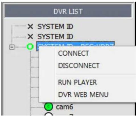
- CONNECT: Connect the NVR selected
DISCONNECT: Dis-connect the NVR Manager from the NVR
RUN PLAYER: Execute the Player for the remote search & playback.
➢ DVR WEB MENU: link the nvr web menu.
7.4.5.6 NVR Information
This panel shows some information of NVR which is currently highlighted from the NVR List.
| DVR INFORMATION |
| DVR NAME: SYSTEM ID |
| DVR ADDRESS: 192, 168, 123, 121 |
| DVR PORT: 9000 |
| USER: ADMIN |
7.4.6 PLAYER
The Player support the features such as followings.
Features of Player
Live video monitoring for the connected NVR
Remote search and playback for the connected NVR
Download the recorded data from the NVR(remote copy)
Control a PAN/TILT camera movement
7.4.6.1 Initial Screen
Executing the 'Player' opens the application separated from the web browser and show the login window such as below picture.
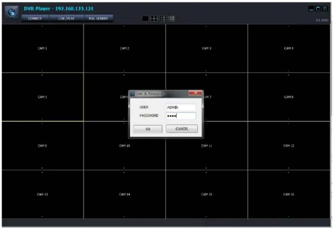
7.4.6.2 Log In


: Enter the USER name of NVR registered in the NVR

: Enter the password for the selected user.
The user authority and allowed functions, live preview, search & playback, PTZ control and etc., are controlled by the setting USER AUTHORITY setting of NVR setup
- USER ID and password is case-sensitive.
7.4.6.3 Live Preview
After login, the live preview screen will be shown such as below.
Features
User log-in/out feature (RECONNECT)
Monitoring the live preview
Snapshot and save the preview video as JPEG
(Admin Only) Control the resolution and quality for transferred video stream directly

The yellow rectangle around video shows the currently selected camera
1: IP of NVR connected remotely
2: display split mode selection

3: WEB Viewer Minimize/Maximize/Close

4: Reconnect/Live & Search/Full Screen
Reconnect Log out and Reconnect
Live/Search Switching between the live preview and the search & playback
Full Screen Full screen video view. Press 'ESC' to return to the window
5: Date & Time of Camera transferred from the NVR
6 : Channel Title and the resolution of the transferred video
For the detail about the JPEG Snapshot/PTZ Control/Video Configuration, refer to the same feature of Web Viewer.
7.4.6.4 Search & Playback

Entering to the search & playback window or Returning to the live preview
Features
User log-in/out feature (RECONNECT)
Switching between the live preview and the search & playback
Search & Playback
Copy the recordings in the NVR to the PC remotely

1: Application title
2: Split mode selection.

3: Playback speed control

Steps for fast playback : x2, x4, x8, x16,x30, x60, x120
Steps for slow playback: 1/2, 1/4, 1/8, 1/16, 1/30, 1/60, 1/120
4: Fast Playback Speed & Direction Control Bar
➢ Mouse wheel up: faster in forward direction
➢ Mouse wheel down: reversely faster
➢ Center click: normal speed playback
Click on the right half of bar : faster in forward direction
➢ Click on the left half of bar: reversely faster
➢ 7 level speed control for each direction
5: View window control
6: Connect/ Live & Play/ Full Screen

7: Calendar Panel: show the selected date for searching. The green color indicates that the recording data exist. Click the date will trigger the searching for the selected day. The searching result is displayed on the time selection table (10).
8 : Copy the recorded video in the NVR to the PC
Select file form: You can select file type to copy to PC.
*.avi: Copy as AVI file form.
The AVI file form for each channel/resolution is created.
One of AVI file form with a maximum capacity of 600MB.
√ *.dvr: Copy as manufacturer's own file form.
TAG name: Folder name where the copied AVI file to be saved.
➢ Channel: Choose the channel required to be copied
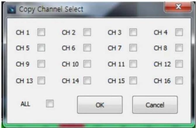
From: The start time of the recording data to be copied
To: The end time of the recording data to be copied
▶ Copy Start: executing the copy operation
TAG name and Channel have to be defined to proceeding the copy.
9: Choose search type between 'EVENT' and 'TIME'. The time selection table tagged '10' in the above picture is used for one of this two search type
TIME Search : select the search mode to 'Time Search'.

Yellow colored cell indicates the currently selected hour and minute.
Green colored cell means that there is the recording data by the continuous recording.
Red colored cell means that there is the event recording data.
➢ Click or double-click on the cell in the minutes bar will start the playback from the selected time.
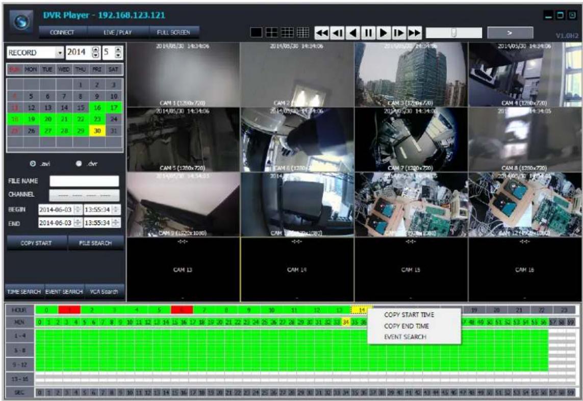
COPY Start Time
COPY End Time
Event Search
Right click on the minute bar will show the pop-up menu such as the left pictures.
: Taking the 'COPY START TIME' from the selected time cell and input it into the 'From' of COPY control panel.
COPY End Time : Taking the 'COPY END TIME' from the selected time cell and input it into the 'To' of COPY control panel.
➢ : Taking the time for 'EVENT SEARCH start time'.
Selection the second by clicking on the 'second' bar will move the second of playback video to the selected second. This is only available during the playback on-going.
Each cells in the time selection table indicates whether the recording data exists or not for that time and channel.

rch mode to 'EVENT Search'.

Event Type(Search Condition)
√ All: For all kinds of recording event
√ Sensor: sensor input event
√ Video Loss: lost video event
➢ Motion Detection : motion detection event
▶ CH ALL: Searching for all channels
CH1/CH2/CH3/CH4: choosing the channel to be searched
➢ Research: execute the event search again
10: Time selection & recording indication table / Event search result window
| 时间 | 1 | 2 | 3 | 4 | 5 | 6 | 7 | 8 | 9 | 10 | 11 | 12 | 13 | 14 | 15 | 16 | 17 | 18 | 19 | 20 | 21 | 22 | 23 | |||||||||||||||||||||||||
| 号 | 0 | 1 | 2 | 3 | 4 | 5 | 6 | 7 | 8 | 9 | 10 | 11 | 12 | 13 | 14 | 15 | 16 | 17 | 18 | 19 | 20 | 21 | 22 | 23 | 24 | 25 | 26 | 27 | 28 | 29 | 30 | 31 | 32 | 33 | 34 | 35 | 36 | 37 | 38 | 39 | 40 | 41 | 42 | 43 | 44 | 45 | 46 | 47 |
| 1-4 | ||||||||||||||||||||||||||||||||||||||||||||||||
| 5-8 | ||||||||||||||||||||||||||||||||||||||||||||||||
| 9-12 | ||||||||||||||||||||||||||||||||||||||||||||||||
| 13-16 | ||||||||||||||||||||||||||||||||||||||||||||||||
| 乙 | 0 | 1 | 2 | 3 | 4 | 5 | 6 | 7 | 8 | 9 | 10 | 11 | 12 | 13 | 14 | 15 | 16 | 17 | 18 | 19 | 20 | 21 | 22 | 23 | 24 | 25 | 26 | 27 | 28 | 29 | 30 | 31 | 32 | 33 | 34 | 35 | 三六 | 三七 | 三八 | 三九 | 四十 | 四十一 | 四十二 | 四十三 | 四十四 | |||
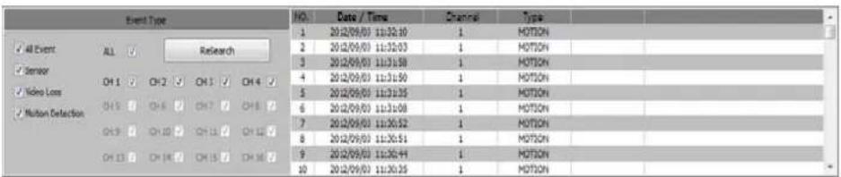
11: display the playback video as a result of searching.
12: show the current playback mode, speed and direction.
VCA Search : Search mode to 'VCA Search'.

TYPE : You can select which Type of VA will be displayed in VA list.
STATUS : You can select start/end time of VA events.
VALUE : You can select the value of VA events.
NAME : You can input ID of VA events which is "Object classifier" possible..
7.5 FILE PLAYER
You can use file player to display copied video as NVR from at your PC.
File player can be installed along with NVR manager.
If you copy the data to USB memory storage, File player will be created automatically.
[Auto generation]

You can display the video copied as NVR from.
1: FILE SELECT: You can select NVR form file to display.
2: FULL SCREEN: Full screen video view. Press 'ESC' to return to the window
3: Split mode selection.
4: Playback speed control


: Forward Fast
Steps for fast playback : x2, x4, x8, x16, x30, x60, x120
Steps for slow playback: 1/2, 1/4, 1/8, 1/16, 1/30, 1/60, 1/120
5: Fast Playback Speed & Direction Control Bar
➢ Mouse wheel up: faster in forward direction
➢ Mouse wheel down: reversely faster
▶ Center click: normal speed playback
Click on the right half of bar : faster in forward direction
➢ Click on the left half of bar: reversely faster
➢ 7 level speed control for each direction
6: View window control
imize the window
: Maximize the window
: Exit the 'Web Viewer'
7: FILE SELECT WINDOW: You can select NVR form file to display
Default path is C:\USERS\account\Document\NVRCopyData
8. Appendix A
Items showing in Log List.
Power ON/OFF
Backup Start
Disk Format
Factory Default
➢ Camera Menu Change
PTZ Menu Change
▶ OSD Menu Change
▶ Monitor Menu Change
➢ Sequence Menu Change
Date/Time Menu Change
System Management Menu Change
Sound Menu Change
➢ User Management Menu Change
▶ Authority Menu Change
- Logout Menu Change
▶ Network Menu Change
▶ DDNS Menu Change
▶ Alarm In Menu Change
▶ Alarm Out Menu Change
▶ Buzzer Out Menu Change
➢ E-Mail Notification Menu Change
▶ Disk Management Menu Change
Record Configuration Change
Record Schedule Change
IP Camera Menu Change
▶ Firmware Upgrade Success
▶ Firmware Upgrade Fail
➢ Admin(User 1 \~ 10) Auto Login
➢ Admin(User 1 \~ 10) Login
➢ Admin(User 1 \~ 10) Password Fail
➢ HDD 1(1 \~ 5) Error For Write
➢ HDD 1(1 \~ 5) Fail For Write
➢ HDD 1(1 \~ 5) Error For Read
➢ HDD 1(1 \~ 5) Fail For Read
Network Connected
Time Adjust
Network Disconnected
NVR Watchdog Reset
Menu Data Backup Succeeded
Menu Data Load Succeeded
Menu Data Backup Failed
Menu Data Load Failed
▶ Camera Menu Changed In Remote
PTZ Menu Changed In Remote
➢ OSD Menu Changed In Remote
➢ Monitor Menu Changed In Remote
➢ Sequence Menu Changed In Remote
Date&Time Menu Changed In Remote
System Management
➢ User Management Menu Changed in Remote
➢ Authority Menu Changed in Remote
To Logout Menu Changed in Remote
▶ Network Menu Changed in Remote
▶ DDNS Menu Changed in Remote
▶ E-Mail Menu Changed in Remote
▶ Alarm input Menu Changed in Remote
▶ Alarm Output Menu Changed in Remote
➢ Buzzer Menu Changed in Remote
➢ Buzzer Menu Changed in Remote
➢ E-Mail Event Menu Changed in Remote
▶ Disk Menu Changed in Remote
➢ Continuous Record Menu Changed in Remote
➢ Schedule Record Menu Changed in Remote
Record Misc Menu Changed in Remote
FAN Error
Copy Success
Copy Fail
Backup Start
Backup Stop
Power OFF
- TABLE OF CONTENTS
- BEFORE INSTALLATION 4
- GETTING STARTED 13
- Live View....15
- SEARCH & PLAYBACK 22
- HOW TO CONFIGURE....31
- CONFIGURING NETWORK 56
- REMOTE....59
- WEB SERVER 59
- Android Viewer / iOS Viewer....71
- DDNS SERVER 74
- DVR MANAGER 76
- FILE PLAYER 92
- Appendix A....95
- BEFORE INSTALLATION
- Before installation
- In operation mode
- Disassembly & Cleaning
- During installation
- While in use
- UPDATING SYSTEM F/W
- WITH THE USB THUMB DRIVE
- How to verify the F/W version
- Preparing new F/W in the USB thumb driver
- Upgrading System from the System Menu
- UPDATING FROM THE WEB MENU
- DESCRIPTION OF FRONT PANEL
- STATUS LED
- 2.IR RECEIVER
- 3.FRONT USB 2.0 PORT
- IR RECEIVER
- STATUS LED
- 3.FRONT USB 1/2 2.0 PORT
- DESCRIPTION OF REAR PANEL
- Power Switch
- 2.VGA Output (Video Graphic Array)
- Audio Inputs
- 4.Power In
- Alarm(Sensor) Inputs, RS-485, and Relay Output
- Rear USB 2.0 (Only the 4CH NVR)
- DIGITAL VIDEO OUT (HDMI)
- CVBS Monitor Output
- 9.RJ-45 Network Port(1G Base-T)
- 10.RJ-45 Local Port( 1G Base-T)
- 11.RJ-45 Cam(PoE) Port (100M Base-T)
- Audio Outputs
- 13.PoE Power In (48V)
- 14.eSATA Connection Port(Option)
- DESCRIPTION OF PIN ASSIGNMENT
- GETTING STARTED
- CONNECT AND SWITCH ON
- START SETUP
- LOADING
- Live View
- TOOL BAR
- STATUS DISPLAY
- LOG OFF
- SETUP
- VA (Video Analytics)
- QUICK COPY
- SEARCH
- DISPLAY
- PTZ
- DIGITAL ZOOM
- [Zoom by using TOOL BAR]
- LOG LIST
- SEARCH & PLAYBACK
- TIME / CALENDAR SEARCH
- PANORAMA SEARCH
- EVENT SEARCH
- COPY
- DVR format
- QUICK MENU
- HOW TO CONFIGURE
- CONFIGURING CAMERA
- TITLE
- ADJUST
- PTZ
- CAM PORT
- TYPE: You can select connection type AUTO/MANUAL/RTSP
- AUTO: Select this mode for peer to peer connection with built-in HUB
- MANUAL: Select this mode for 3 rd party ONVIF camera or camera is located in the network connected "Ethernet" / "Local" port.
- DETAIL(....): Modify the configuration of the camera if you need.
- VIRTUAL PORT
- CONFIGURING DISPLAY
- OSD
- MONITOR
- SEQUENCE
- CONFIGURING DISK
- SETUP
- FORMAT
- CONFIGURING SYSTEM
- DATE TIME
- MANAGEMENT
- SOUND
- CONFIGURING EVENT / SENSOR
- SENSOR INPUT
- ALARM OUTPUT SETUP
- BUZZER OUTPUT SETUP
- E-MAIL SETUP
- CONFIGURING USER
- USER REGISTER
- USER AUTHORITY
- LOG-OUT
- CONFIGURING RECORD
- MAIN STREAM
- SUB STREAM
- SCHEDULE
- OPTION
- CONFIGURING NETWORK
- ETHERNET PORT
- LOCAL PORT
- DDNS
- REMOTE
- WEB SERVER
- CONNECT TO WEB SERVER
- Tested Web Browser List
- Features
- Initial Page of Web Configuration
- WEB VIEWER (Active-X)
- Tested Web Browser
- Installation and Execution
- [Microsoft IE]
- ActiveX WEB Viewer
- [Google Chrome]
- [Mozilla Firefox]
- Initial Screen of Web Viewer
- Log In
- Live Preview
- JPEG Snapshot/ PTZ control / Video Configuration /Live Audio
- Search & Playback
- LIVE / PLAY
- 4: Fast Playback Speed & Direction Control Bar
- 5: View window control
- 6: Reconnect/Live&Search/Full Screen
- : Copy the recorded video in the NVR to the PC
- 9: Choose search type between 'EVENT' and 'TIME'. The time selection table tagged in the above picture is used for one of this two search type.
- Android Viewer / iOS Viewer
- Main feature
- How to use
- Quick Connect
- NVR LIST
- How to add NVR to the List
- How to connect
- DDNS SERVER
- HOW TO REGISTER
- REGISTER
- Input NVR information.
- DVR MANAGER
- INSTALLATION
- EXECUTION
- LIVE VIDEO MONITORING
- 3:CONFIG:
- CONNECTION MANAGER
- Monitoring live video stream
- Swap Camera Position
- Digital Zoom on the Live View
- JPEG Snapshot/ PTZ control / Video Configuration /Live Audio
- DVR lst
- NVR Information
- PLAYER
- Features of Player
- Initial Screen
- Log In
- Live Preview
- Search & Playback
- 6: Connect/ Live & Play/ Full Screen
- FILE PLAYER
- 5: Fast Playback Speed & Direction Control Bar
- 6: View window control
- 7: FILE SELECT WINDOW: You can select NVR form file to display
- Appendix A
Brand : Ganz
Model : PixelMaster GXi NR1-4F23S
Category : Security Camera