
Professional LCB2-3 - Uncategorized LYNX - Free user manual and instructions
Find the device manual for free Professional LCB2-3 LYNX in PDF.


| Product Type | Side Burner |
| Brand | Lynx |
| Model | Professional LCB2-3 |
| Compatible Grill Models | L27, L36, L54, L42, L30 |
| Tools Required | 7/16 Wrench |
| Kit Contents | Adjustable side burner mounting bracket, side shelf mounting bracket with 7/16 fasteners, decorative cover (for L27/L36) |
| Installation Steps | Remove side shelf and cabinet back panel, mount burner to supports, correct misalignment, tighten fasteners, reattach shelf |
| Gas Connection | Refer to illustrations; perform leak test with soap and water |
| Electrical Connection | Disconnect transformer from grill, plug in side burner |
| Safety | Leak test all gas line fittings before use |
| Material | Stainless steel (typical) |
| Dimensions (approx) | 12 inches wide, 24 inches deep (estimated) |
| Weight (approx) | 15 lbs (estimated) |
| Power Output (estimated) | 15,000 BTU |
| Adjustability | Brackets can be raised or lowered to correct misalignment |
Frequently Asked Questions - Professional LCB2-3 LYNX
User questions about Professional LCB2-3 LYNX
0 question about this device. Answer the ones you know or ask your own.
Ask a new question about this device
Download the instructions for your Uncategorized in PDF format for free! Find your manual Professional LCB2-3 - LYNX and take your electronic device back in hand. On this page are published all the documents necessary for the use of your device. Professional LCB2-3 by LYNX.
USER MANUAL Professional LCB2-3 LYNX
TOOLS REQUIRED: 7/16 Wrench
CONTENTS OF KIT: An adjustable side burner mounting bracket
Side shelf mounting bracket with 7/16 fasteners
Decorative cover for the L27 and L36 models
The side burner support bracket comes preassembled for the L27 and L36
INSTRUCTIONS FOR MODELS L36 and L27:
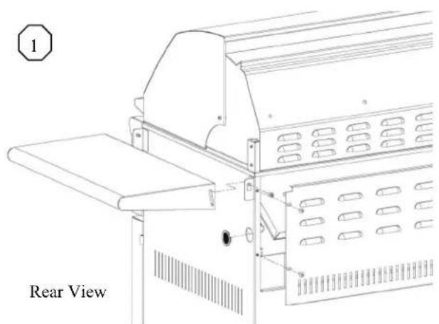
- Remove the right hand side shelf and the cabinet back panel (fig. 1)
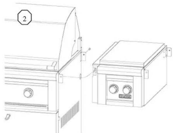
- Mount the LCB2-3 side burner to the supports (fig. 2)
- If needed, any misalignment can be corrected by 1st measuring the amount of misalignment, 2nd loosening the bracket support fasteners. 3rd raise or lower the bracket according to your measurements. Tighten the fasteners. (fig 3)
- Hang the side shelf removed in step 1 on the right side shelf support pins of the side burner (Fig. 6, pg. 2)
natural_image
Technical line drawing of two industrial appliances with control panel and door (no text or symbols)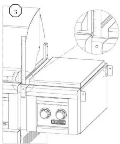
natural_image
Technical line drawing of a mechanical device with control panel and zoomed-in detail view (no text or symbols)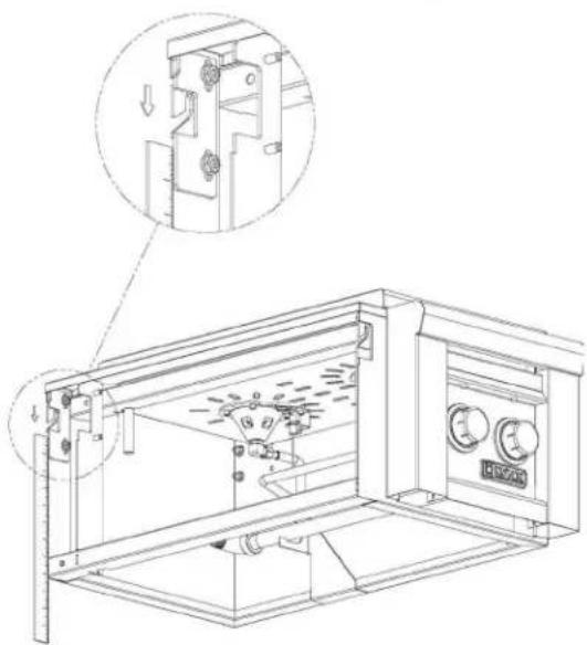
natural_image
Technical line drawing of a mechanical device with internal components and a magnified inset showing a detail (no text or symbols)INSTRUCTIONS FOR MODELS L54, L42, L30:
- Remove the right hand side shelf. See fig.1 on page 1
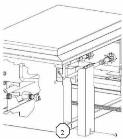
- At the rear, remove the decorative cover (1) on the left hand side of the LCB2-3 by removing the Philips head screw and sliding it out. This also gives access to the gas piping connections. (Fig. 2)
- Locate the mounting bracket on the inner most bracket support (Fig 3). Remove the 7/16 fasteners holding it in place Reinstall the mounting bracket on the rear most bracket support and secure it with the 7/16 fasteners
- As in step 3 on page 1, correct any misalignment in the shelf
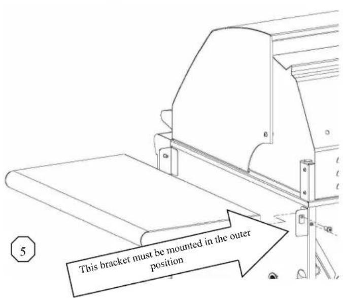
- Move the shelf mounting bracket on the right hand side, to the outermost mounting holes using the 7/16 nuts, and tighten. (Fig. 5)
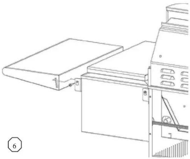
- Hang the side shelf removed in step 1, pg. 1 to the right side of side burner on the shelf mounting bracket pins (Fig 6)
natural_image
Technical line drawing of a mechanical assembly with gears and shafts (no text or symbols)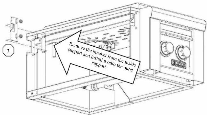
natural_image
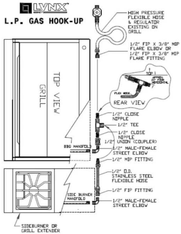
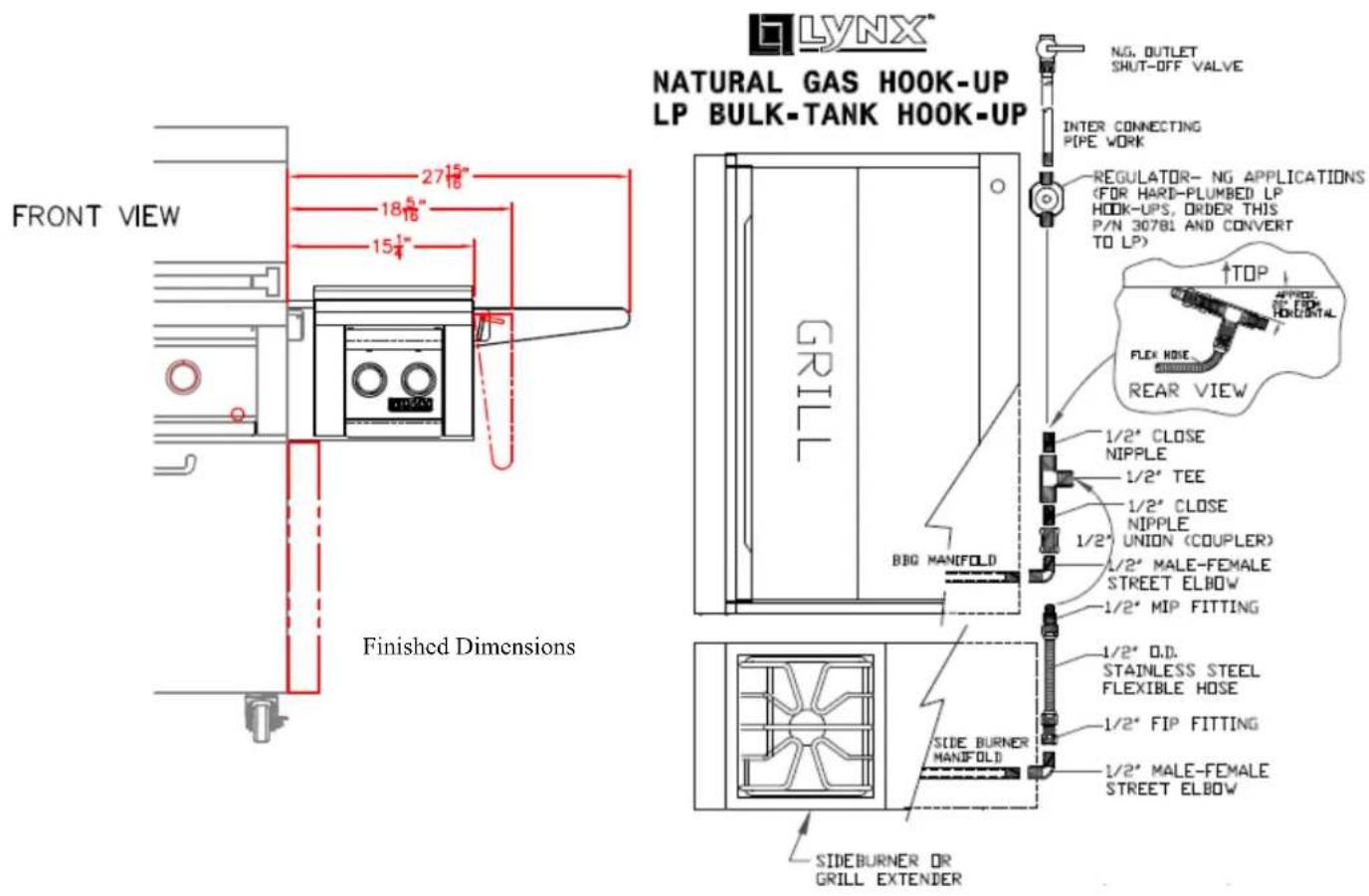
Technical line drawing of a mechanical assembly or machine component (no text or symbols visible)Once the side burner is mounted to the grill the gas connections can be made. Refer to the illustrations on the right for proper gas installation examples.
After the side burner gas connections are made it is recommended that a leak test be done on all gas line fittings. Apply a soap and water solution to all connections and look for bubbles to form which indicate a gas leak. If no bubbles are present, make the electrical connections
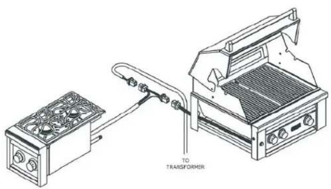
The side burner is electrically connected to grill at the transformer. Disconnect the transformer from the grill and plug in the side burner as shown in the illustration below.
Brand : LYNX
Model : Professional LCB2-3
Category : Uncategorized