
CLG 5.0 - Car alarm BLAUPUNKT - Free user manual and instructions
Find the device manual for free CLG 5.0 BLAUPUNKT in PDF.

| Product Type | Central Lock Gun (Alarm Component) |
| Model | CLG 5.0 |
| Brand | Blaupunkt |
| Wiring Type | 5-Wire |
| Operating Voltage | 12V DC |
| Actuating Force | 3.0 ± 0.2 kg |
| Endurance (Cycles) | 100,000+ up/down movements |
| Movement Stroke | 18 ± 2 mm |
| Load Current | 0.18 A ± 10% |
| No-Load Current | 0.14 A ± 5% |
| Operating Temperature Range | -20°C to +70°C |
| Housing Material | Metal, Plastic & ABS |
| Wire Length | 160 mm |
| Dimensions (L x W x H) | 140 x 60 x 30 mm |
| Weight | 0.097 kg |
| Key Features | Sealed housing, motor, 360° rotation head, colored wires |
| Installation Location | Front and rear doors (driver/vice-driver seats) |
| Compatibility | Designed for car door locking systems; verify fitment before install |
| Safety Notes | Do not immerse in liquid; avoid high temperature exposure; do not disassemble |
| Maintenance | Check wiring and fuse if not working; replace if faulty |
Frequently Asked Questions - CLG 5.0 BLAUPUNKT
User questions about CLG 5.0 BLAUPUNKT
0 question about this device. Answer the ones you know or ask your own.
Ask a new question about this device
Download the instructions for your Car alarm in PDF format for free! Find your manual CLG 5.0 - BLAUPUNKT and take your electronic device back in hand. On this page are published all the documents necessary for the use of your device. CLG 5.0 by BLAUPUNKT.
USER MANUAL CLG 5.0 BLAUPUNKT
CENTRAL LOCK GUN CLG 2.0 CLG 5.0

natural_image
Two gray industrial sensors labeled CLG 2.0 and CLG 5.0, each with colored wires (no additional text or symbols visible)Enjoy it.
INTRODUCTION STRUCTURE & FUNCTIONS
Proper system planning is vital in order to maximize the device's performance and road safety. Plan your installation carefully to avoid compromising performance reliability of the system. Consult an authorized Blaupunkt delaler for installation or reparation. Read the manual carefully before operating the device for the first time.
Safety Notes
- Please understand the structure of your car door clearly before installation. Please make sure the central lock gun is compatible for your car door locking system and ensure that the installation will not affect the window.
- Please raise and lower the windows several times to make sure that there is no scrathing occurred after installing the system.
- Please do not immerse the central lock gun in liquid or let it get wet. Please do not expose it under the sunlight at the high temperature.
- The product is consist of sophisticated electronic materials, please do not attempt to disamble or take apart it by yourself. Please refer to the experienced or qualified professional staff.
This manual may be updated from time to time without any notice.
Disclaimer
In no event shall Blaupunkt be liable for any direct, indirect, punitive, incidental, special consequential damages to property or life and whatsoever arising out of or connected with the use or misuse of our products.
USA & CANADA: This product is not intended for sale in the United States and Canada. If purchased in the U.S. or Canada, this product is purchased on as-is basis. No warranty, whether expressed or Implied is provided in the U.S. or Canada.
Recycling and Disposal

CLG 2.0 CLG 5.0

natural_image
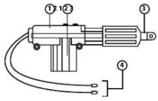
Pure electrical circuit lines without any symbolsFunctions
- Sealed Housing
- Motor
- 360° Rotation Head
- Wires
SPECIFICATION
CLG 2.0
- Type: 2-Wire
• Operating Voltage: 12V - Actuating Force: 3.0 ± 0.2 ~kg
• Endurance (up & down) : 100,000+ times
• Movement Stroke: 18±2mm - Load Current: 0.18A±10%
• No-load Current : 0.14A±5% - Operating Temperature Range: -20°C--+70°C
• Material: Metal, Plastic & ABS - Wire Length: 160mm
• Dimension/Size (LxWxH) : 140x60x30mm - Weight: 0.088kg
CLG 5.0
- Type:5-Wire
• Operating Voltage: 12V - Actuating Force: 3.0 ± 0.2 ~kg
• Endurance (up & down) : 100,000+ times
• Movement Stroke: 18±2mm - Load Current: 0.18A=10%
- No-load Current: 0.14A±5%
- Operating Temperature Range: -20°C--+70°C
• Material: Metal, Plastic & ABS - Wire Length: 160mm
• Dimension/Size (LxWxH): 140x60x30mm - Weight: 0.097kg
INSTALLATION INSTRUCTION WIRING DIAGRAM
Front Door Driver-seat
(The same operation as the similar back door)
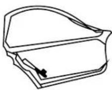
- Remove the door panel, put the actuator and metal piece on the metal board stabilize. Then, put the connecting stick into the right hole and connect it straight down to the actuator and spot.
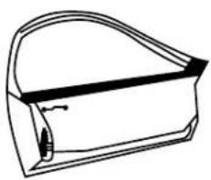
natural_image
Simple line drawing of a curved mechanical part or housing (no text or symbols)- Then, pull the stick inside and check whether it moves with the other locks or not.
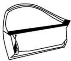
natural_image
Simple line drawing of a rectangular container or housing with a curved top and side slot (no text or symbols)Front Door Vice-Driver Seat
(The same operation as the similar back door)
- Remove the door panel, put the actuator and metal piece on the external metal board stabilize. Then, put the connecting stick into the left hole and then pull the stick into the left hole.
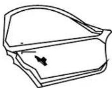
natural_image
Line drawing of a door handle with a black arrow pointing to the side panel (no text or symbols)- Then, pull the stick down and extend it, connect the spot to the actuator.
natural_image
Line drawing of a closed book or notebook with a handle and spout (no text or symbols)1 Master 3
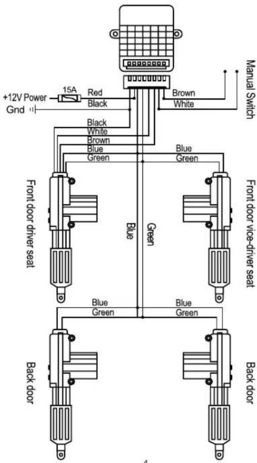
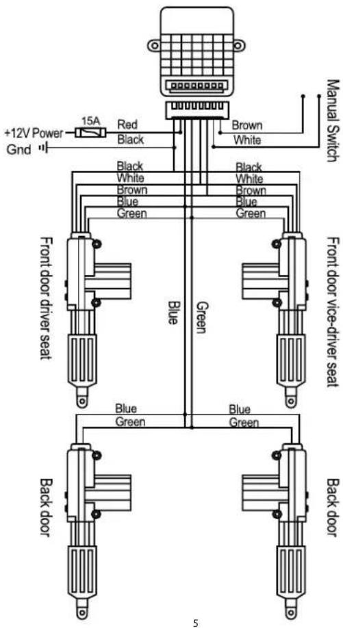
WIRING DIAGRAM TROUBLESHOOTING
2 Master 2
If any of the following problem occur, please resort to Troubleshooting for the possible solutions. Consult Blaupunkt authorized dealer if problem persist.
| Problems | Solutions |
| Central lock gun is not working. | Check for the wires connection and fuse. |
| Replace with a new central lock gun. |

Designed and engineered by Blaupunkt Competence Centre
CLG 2.0
1 521 20 009 23 01
CLG 5.0
1 521 20 010 23 01
Brand : BLAUPUNKT
Model : CLG 5.0
Category : Car alarm