PixelPro ZN-DNT352XE - Security Camera Ganz - Free user manual and instructions
Find the device manual for free PixelPro ZN-DNT352XE Ganz in PDF.


| Product Type | Security Camera (IP Dome) |
| Brand | Ganz |
| Model | PixelPro ZN-DNT352XE |
| Resolution | 5 Megapixels (2592 x 1944) |
| Night Vision | IR LEDs up to 30 meters |
| Lens | 2.8 ~ 12mm varifocal, F1.6 |
| Field of View | Horizontal: 100° ~ 35° |
| Day/Night | ICR filter, true day/night |
| Compression | H.265 / H.264 / MJPEG |
| Motion Detection | Yes, configurable zones |
| Audio | Built-in microphone, 1-way audio |
| Network | Ethernet 10/100, PoE (802.3af) |
| Weather Rating | IP66 (indoor/outdoor) |
| Dimensions | Φ150 x 110 mm |
| Weight | Approx. 1.2 kg |
| Power Supply | PoE or 12V DC, 12W max |
| Operating Temperature | -10°C ~ 50°C |
| Storage | MicroSD slot (up to 256GB) |
| Maintenance | Clean lens with dry cloth; avoid solvents |
| Safety | CE, FCC compliant; surge protection |
| Spare Parts | Replacement IR board, lens assembly available |
| Repairability | Modular design; user-replaceable components |
| General Info | Manufacturer: Ganz; Manual in PDF |
Frequently Asked Questions - PixelPro ZN-DNT352XE Ganz
User questions about PixelPro ZN-DNT352XE Ganz
0 question about this device. Answer the ones you know or ask your own.
Ask a new question about this device
Download the instructions for your Security Camera in PDF format for free! Find your manual PixelPro ZN-DNT352XE - Ganz and take your electronic device back in hand. On this page are published all the documents necessary for the use of your device. PixelPro ZN-DNT352XE by Ganz.
USER MANUAL PixelPro ZN-DNT352XE Ganz
This symbol is intended to alert the user to the presence of un-insulated “dangerous voltage” within the product’s enclosure that may be of sucient magnitude to constute a risk of electric shock to persons.

This symbol is intended to alert the user to the presence of important operang and maintenance (servicing) instrucons in the literature accompanying the appliance.
Table of Contents
- FEATURES ....4
- PACKAGE CONTENTS .... 5
- PART NAMES ...... 6
- INSTALLATION ....7
4.1.Installaon Template....8
4.2. Seing the Lens Posion ....9
4.3. Seing the Image Aribute ....9
- CONNECTIONS....10
- CONFIGURATION .... 13
6.1.Set up network environment....13
6.2. View video on web page....13
6.2.1.View video using IPAdmin Tool 14
6.2.2.View video using IP address....15
6.3. Reset....15
6.3. Reset....15
6.4. Factory Default....15
APPENDIX (A): SPECIFICATIONS....16
Summary 16
Electrical Characteristics ....17
Environment Condion....17
Mechanical Condion 17
APPENDIX (B): POWER OVER ETHERNET 18
PoE compatibility ....18
Power classificaon....18
APPENDIX (C): DIMENSIONS....19
APPENDIX (D): HEXADECIMAL-DECIMAL CONVERSION TABLE....20
REVISION HISTORY 21
1. FEATURES
Camera
• Full HD outdoor dome IP camera (Vandal proof)
• High quality compression in real me streaming
• 1/2.7" High Quality CMOS Image Sensor
• True Day / Night (ICR) and WDR
- Improvement of color rolling suppression
Streaming
- Dual streaming mode (such as dierent codec/resoluon/bit rate and so on.)
- De-interlacing on DSP
- Burnt-in text supported
• Unicast/Mulcast supported
Video/Audio
- Video compression: H.264/MPEG4 (Planned for the future release.)/MJPEG, 25/30FPS@1080p(PAL/NTSC)
• Audio compression: G.711(μLaw, aLaw)/PCM - Analog video out for external monitors
• Video moon detecon supported - Two-way mono audio supported
Network
• RTSP/ HTTP protocol supported
• 10/100 Base-T Ethernet
Additional Features
- Micro SD card supported
- PoE supported
• Built-in Video Content Analysis (Planned for the next release.) - SDK (Soware Development Kit) provided
2. PACKAGE CONTENTS
Unpack carefully and handle the equipment with care. The packaging contains:
Camera

DC Jack Cable

Video out cable

Installaon template

Quick installaon guide

Clamping core
To prevent electromagnec interference


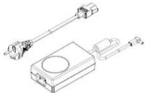
DC power adaptor
natural_image
Technical line drawing of a mechanical assembly with no visible text or symbols9-pin and 2-pin terminal block

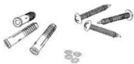
Screws and anchors
Hex wrench driver

Silicon waterproof band

The above contents are subject to change without prior noce.
3. PART NAMES
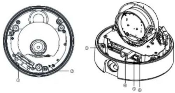
* Models herein and their appearance are subject to change without any prior notice.
① Fan
The fan and heater (underneath the black panel) are implemented for controlling temperature and moisture of the internal device.
4. INSTALLATION
natural_image
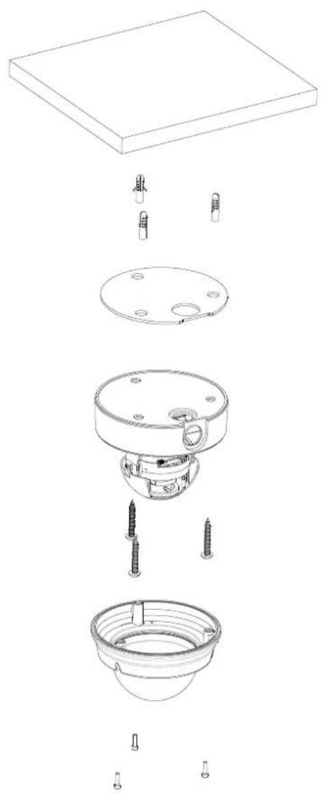
Exploded view diagram of a mechanical assembly showing internal components like a base plate, casing, and screw installation (no text or labels)1) Place the installaon template that is provided in the package on the desired posion of installaon.
2) Aach the waterproof silicon band on the boom plate of the device.
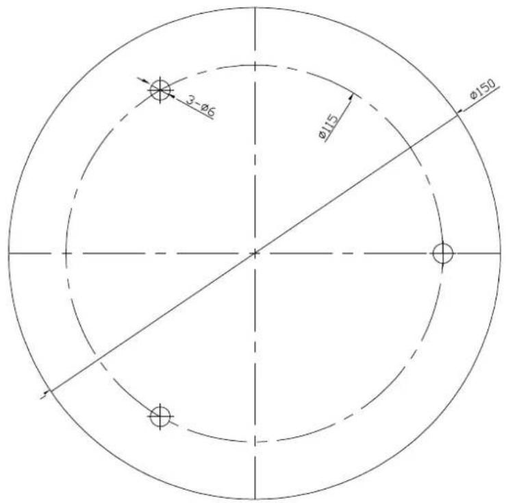
3) Drill three holes on the template and insert anchor blocks into the holes. Fasten the camera with screws.
4) Make sure the cables are properly connected by checking the LED buon.
5) Adjust the lens posion by referring to 4.2. Seng the Lens Posion.
6) Put the dome cover on the main body of the camera. Make sure the main body and the cover t each other into place.
7) Fasten the cover with screws.

When assembling the main body of the camera and its dome cover, make sure they t each other into place.

The camera may fall o the ceiling even aer the proper installaon and mounng. To prevent any accident, make sure the ceiling is rm and stable enough to support the camera. If any reinforcement is needed, consult with your safety personnel and proceed with the installaon.
4.1. Installation Template
4.2. Setting the Lens Position
Set the lens posion and adjust the zoom and focus by performing procedures as below.
1) Remove the dome cover.
2) Adjust the lens to the desired position by manually moving its body in the following direcons.

natural_image
Diagram of a mechanical device with rotating components and red curved arrows indicating rotation (no text or symbols)A. Rotate the lens

B. Pan the lens boom holder

natural_image
Simple line drawing of a person operating machinery with a bicycle icon and red motion arrow (no text or symbols)C. Tilt the lens
3) Connect to the web page of the device to see its real-me image. Refer to step 6. Conguraon for details about using its web page.
4) Unscrew the zoom puller by turning it counterclockwise. Move it le or right and set the lens to the desired zoom posion. Aer the seng, ghten the zoom puller again by turning it clockwise.
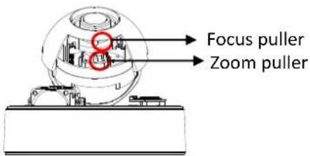
5) Unscrew the focus puller by turning it counterclockwise. Move it le or right and adjust the image focus. Aer the seng, ghten the focus puller again by turning it clockwise.
4.3. Setting the Image Attribute
You can set the image aribute of camera through the webpage.
The menu of image aribute can be seen under Setup > Video & Audio > Camera. Brightness, contrast, saturaon and sharpness can be adjusted.
5. CONNECTIONS
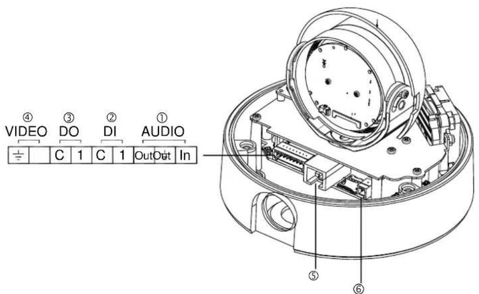
① Audio input/output
The camera has a mono audio input and a mono audio output. Since the output power for the audio is low, an amplifier speaker is needed for a clearer sound (Do not use a headphone or earphone directly to the camera).

② Analog video output conneccon
Connect a display device (such as a monitor) to the video output connector and check if the camera is installed properly.
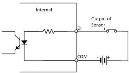
③ Sensor (DI) conncon
The camera provides 1 channel D/I. It can be connected to either a voltage type sensor or a relay type sensor as the following gures. It can be selected by soware.
Input voltage range: 0VDC minimum to 5VDC maximum, Max 50mA
Input voltage threshold: 1.5V

Caution
Do not exceed the maximum input voltage or relay rate.
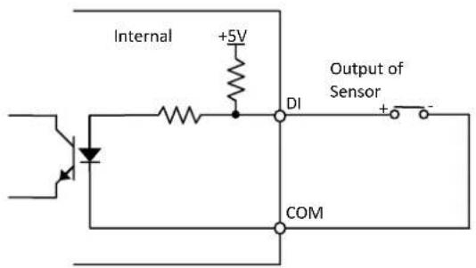
Relay Type
Voltage Type
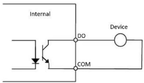
④ Alarm (DO) conncon
Only the relay type is supported.
Relay Rang: Max 24VAC 500mA or 12VDC 1A

Caution
Do not exceed the maximum relay rang.
Relay Type

Caution
Must connect GND port which is located between systems.
⑤ LAN connection
This is a RJ45 LAN connector for 10/100 Base-T Ethernet. Connect a LAN cable.
LED1 LED2
This LED lights up as orange and turns green when the encoder is powered on.
⑥ 12V DC Power
A 12 DC power connector is required for this device.
12V
Black
Red
6. CONFIGURATION
6.1. Set up network environment
The default IP address of your IP device is 192.168.XXX.XXX. You can nd the available IP address from the MAC address of your device. Please make sure the device and your PC are on the same network segment before running the installaon. If the network segment between your PC and the device is dierent, change your PC's sengs as below.
IP address : 192.168.xxx.xxx
Subnet mask: 255.255.0.0

6.2. View video on web page
View the live video on a web page using your IP device and its IP address. You can use the IPAdminTool or enter the IP address on the web page.
6.2.1. View video using IPAdmin Tool
IPAdminTool automacally searches all acvated network encoders and IP cameras and shows the product name, IP address, MAC address and etc. IPAdminTool is provided with SDK at the following SDK path.
{SDK root}\BIN\TOOLS\AdminTool\
To use the IPAdminTool and view the live video on a web page:
- Start IPAdminTool. Names and info of currently acvated devices appear as a list.
- Right-click on the desired device and select Web view.
- When the dialog box appears to request user name and password, enter the default value for the administrator account (case-sensitive) as below:
ID: root
Password: pass
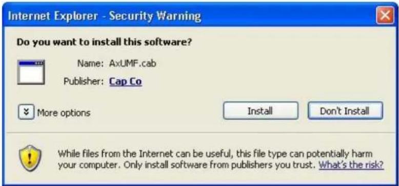
- Click the installaon warning message on the view page and click the Install buon on the warning message box. If the page is not responding aer the installaon, refresh the page.
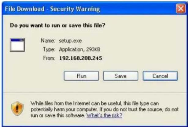
- Install the setup.exe le by clicking the link shown on the main page.
![Please install program [setup.exe]](/content/2026/06/1169049/images/7512da5cb8b2f9f5ba93b012d54f6a18e6b933ef4c18637f65eefb8672497bcf.jpg)
- Follow the instrucons of the dialog boxes and complete the installaon.
- When the dialog box appears to request user name and password, enter the default value for the administrator account (case-sensitive) as below:
ID: root
Password: pass
- Refresh the page and check if the live image is displayed successfully.
6.2.2.View video using IP address
View the live video on a web page using your IP device and its IP address. To have the correct IP address ready and use it on a web page:
- Convert a MAC address to an IP address or check the IP address on the IPAdminTool. Refer to Appendix (D). Hexadecimal-Decimal Conversion Table.
(The MAC address is aached on the side or boom of the device.)

- Open a web browser and enter the IP address of the device.
- Click Connue to this website on the Security Cercate Alert page.
- Click pop-up blocked and install the AcveX control as below. You need to install the AcveX for displaying the images.
- Wait for a few seconds while the web page loads. The live video is displayed.
6.3. Reset
- While the device is in use, press the Reset buon.
- Wait for the system to reboot.
6.4. Factory Default
- Press reset buon and hold.
- Release the Reset buon aer 5 seconds unl LED blinks.
- Wait for the system to reboot.
The factory default sengs can be inferred as follows:
IP address: 192.168.xx.yy
Network mask: 255.255.0.0
Gateway: 192.168.0.1
User ID: root
Password: pass
APPENDIX (A): SPECIFICATIONS
Summary
| Camera Module | ||
| CMOS | Image Sensor | 1/2.7" 1080p CMOS |
| Eecve Pixels | 1920x1080 | |
| Scanning system | Progressive scanning | |
| ELECTRICAL | Resoluon | 1920 x 1080 |
| Min.Illuminaon | Color: 1.0 lux, F1.2BW: 0.001 lux, F1.2 | |
| AGC Control | Auto | |
| Lens | 3.0~9.0mm Vari-Focal F1.2 | |
| Day & Night | Removal IR Cut Filter | |
| Video | ||
| Compression Format | H.264, MPEG-4 ^1 , MJPEG Selectable per Stream | |
| Number of Streams | Dual Stream, Congurable | |
| Resoluon | 1920x1080, 1280x720, 800x450, 480x270, 320x180 | |
| Compression FPS | 25/30fps@1080p | |
| Moon Detecon | Built-in | |
| Burnt-in Text (Digital) | Video stream overlay text | |
| Output | Analog video output for installaon only | |
| Audio | ||
| Input/output | 1/1 channel | |
| Compression Format | G.711 | |
| Funcon | ||
| Digital Input/output | 1/1 channel | |
| RS-485 | Not supported | |
| Network | 10/100 Base-T | |
| Power over Ethernet | Supported | |
| Protocol | TCP/IP, UDP/IP, HTTP, RTSP, RTCP, RTP/UDP, RTP/TCP, SNTP, mDNS, UPnP, SMTP, SOCK, IGMP, DHCP, FTP, DDNS, SSL v2/v3, IEEE 802.1X, SSH, SNMP v2/v3 | |
| SD Slot | Supported (MicroSD)※ Micro SD Card is not included | |
Electrical Characteristics
| Power Source | DC 12V / PoE IEEE802.3af (Class 0) |
| Power Consumpon | 1100mA (Heater On) |
| Video Output | 1 Vp-p, 75Ω, Composite |
| Audio Input | Linein, 1.43Vp-p(Min 1.35Vp-p, max 1.49 Vp-p), 39 KΩ |
| Audio Output | Lineout, 46mW Power, 16 Ω |
| D/I | Max 50mA@5VDC, TTL level 4.5V threshold |
| D/O | Max 500mA@24VAC or 1A@12VDCOn-state resistance: 50 Ω (max connuous) |
Environment Condition
| Operang Temperature | Operang RangeDC12V : -40°C ~ 50°C (-40°F ~ 122°F)PoE : 0 °C ~ 50 °C (32°F ~ 122°F)Cold StartDC12V : -20°C (-4°F)PoE: 0 °C (32°F) |
| Operang Humidity | Up to 85% RH |
Mechanical Condition
| Material | Aluminum Die Casng |
| Color | White |
| Dimension | Housing : 115 ( ) x 129(H) mmDome : 100( ) mm |
| Weight (Approx) | 1.2kg |
APPENDIX (B): POWER OVER ETHERNET
The Power over Ethernet (PoE) is designed to extract power from a convenonal twisted pair Category 5 Ethernet cable, conforming to the IEEE 802.3af Power-over-Ethernet (PoE) standard. IEEE 802.3af allows for two power opons for Category 5 cables.
The PoE module signature and control circuit provides the PoE compatibility signature and power classicaon required by the Power Sourcing Equipment (PSE) before applying up to 15W power to the port.
The high eciency AC/DC converter operates over a wide input voltage range and provides a regulated low ripple and low noise output. The AC/DC converter also has built-in overload and short-circuit output protecon.
Note: For proper acvaon of 12V PoE, the Category 5 cable must be shorter than 140m and conform the PoE standard.
PoE compatibility
With non Power Sourcing Equipment (PSE)
When it is connected with non PSE, the power adaptor should be connected.
With power adaptor
Connecng both PSE and power adaptor does not do any harm to the product, but power adaptor will be the only power source for the device as it has priority over PSE. In this case, disconnecting power adaptor while it is operang will cause the device to reboot. And PoE will be the power source for the device aer the reboot.
Power classification
The PoE Power Class supported by the IP device is Class 0.
| Class | Usage | Minimum Power Levels Output at the PSE | Maximum Power Levels at the Powered Device |
| 0 | Default | 15.4W | 0.44 to 12.95W |

Unlike the other way, disconnectg PSE or PoE doesn't reboot the device as long as a power adaptor is connected.
APPENDIX (C): DIMENSIONS
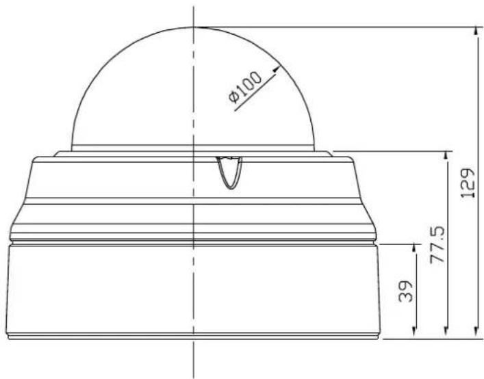

(Unit: mm)
APPENDIX (D): HEXADECIMAL-DECIMAL CONVERSION TABLE
Refer to the following table when you convert the MAC address of your device to IP address.
| Hex | Dec | Hex | Dec | Hex | Dec | Hex | Dec | Hex | Dec | Hex | Dec | Hex | Dec |
| 00 | 0 | 25 | 37 | 4A | 74 | 6F | 111 | 94 | 148 | B9 | 185 | DE | 222 |
| 01 | 1 | 26 | 38 | 4B | 75 | 70 | 112 | 95 | 149 | BA | 186 | DF | 223 |
| 02 | 2 | 27 | 39 | 4C | 76 | 71 | 113 | 96 | 150 | BB | 187 | E0 | 224 |
| 03 | 3 | 28 | 40 | 4D | 77 | 72 | 114 | 97 | 151 | BC | 188 | E1 | 225 |
| 04 | 4 | 29 | 41 | 4E | 78 | 73 | 115 | 98 | 152 | BD | 189 | E2 | 226 |
| 05 | 5 | 2A | 42 | 4F | 79 | 74 | 116 | 99 | 153 | BE | 190 | E3 | 227 |
| 06 | 6 | 2B | 43 | 50 | 80 | 75 | 117 | 9A | 154 | BF | 191 | E4 | 228 |
| 07 | 7 | 2C | 44 | 51 | 81 | 76 | 118 | 9B | 155 | C0 | 192 | E5 | 229 |
| 08 | 8 | 2D | 45 | 52 | 82 | 77 | 119 | 9C | 156 | C1 | 193 | E6 | 230 |
| 09 | 9 | 2E | 46 | 53 | 83 | 78 | 120 | 9D | 157 | C2 | 194 | E7 | 231 |
| 0A | 10 | 2F | 47 | 54 | 84 | 79 | 121 | 9E | 158 | C3 | 195 | E8 | 232 |
| 0B | 11 | 30 | 48 | 55 | 85 | 7A | 122 | 9F | 159 | C4 | 196 | E9 | 233 |
| 0C | 12 | 31 | 49 | 56 | 86 | 7B | 123 | A0 | 160 | C5 | 197 | EA | 234 |
| 0D | 13 | 32 | 50 | 57 | 87 | 7C | 124 | A1 | 161 | C6 | 198 | EB | 235 |
| 0E | 14 | 33 | 51 | 58 | 88 | 7D | 125 | A2 | 162 | C7 | 199 | EC | 236 |
| 0F | 15 | 34 | 52 | 59 | 89 | 7E | 126 | A3 | 163 | C8 | 200 | ED | 237 |
| 10 | 16 | 35 | 53 | 5A | 90 | 7F | 127 | A4 | 164 | C9 | 201 | EE | 238 |
| 11 | 17 | 36 | 54 | 5B | 91 | 80 | 128 | A5 | 165 | CA | 202 | EF | 239 |
| 12 | 18 | 37 | 55 | 5C | 92 | 81 | 129 | A6 | 166 | CB | 203 | F0 | 240 |
| 13 | 19 | 38 | 56 | 5D | 93 | 82 | 130 | A7 | 167 | CC | 204 | F1 | 241 |
| 14 | 20 | 39 | 57 | 5E | 94 | 83 | 131 | A8 | 168 | CD | 205 | F2 | 242 |
| 15 | 21 | 3A | 58 | 5F | 95 | 84 | 132 | A9 | 169 | CE | 206 | F3 | 243 |
| 16 | 22 | 3B | 59 | 60 | 96 | 85 | 133 | AA | 170 | CF | 207 | F4 | 244 |
| 17 | 23 | 3C | 60 | 61 | 97 | 86 | 134 | AB | 171 | D0 | 208 | F5 | 245 |
| 18 | 24 | 3D | 61 | 62 | 98 | 87 | 135 | AC | 172 | D1 | 209 | F6 | 246 |
| 19 | 25 | 3E | 62 | 63 | 99 | 88 | 136 | AD | 173 | D2 | 210 | F7 | 247 |
| 1A | 26 | 3F | 63 | 64 | 100 | 89 | 137 | AE | 174 | D3 | 211 | F8 | 248 |
| 1B | 27 | 40 | 64 | 65 | 101 | 8A | 138 | AF | 175 | D4 | 212 | F9 | 249 |
| 1C | 28 | 41 | 65 | 66 | 102 | 8B | 139 | B0 | 176 | D5 | 213 | FA | 250 |
| 1D | 29 | 42 | 66 | 67 | 103 | 8C | 140 | B1 | 177 | D6 | 214 | FB | 251 |
| 1E | 30 | 43 | 67 | 68 | 104 | 8D | 141 | B2 | 178 | D7 | 215 | FC | 252 |
| 1F | 31 | 44 | 68 | 69 | 105 | 8E | 142 | B3 | 179 | D8 | 216 | FD | 253 |
| 20 | 32 | 45 | 69 | 6A | 106 | 8F | 143 | B4 | 180 | D9 | 217 | FE | 254 |
| 21 | 33 | 46 | 70 | 6B | 107 | 90 | 144 | B5 | 181 | DA | 218 | FF | 255 |
| 22 | 34 | 47 | 71 | 6C | 108 | 91 | 145 | B6 | 182 | DB | 219 | ||
| 23 | 35 | 48 | 72 | 6D | 109 | 92 | 146 | B7 | 183 | DC | 220 | ||
| 24 | 36 | 49 | 73 | 6E | 110 | 93 | 147 | B8 | 184 | DD | 221 |
REVISION HISTORY
| MAN# | DATE(M/D/Y) | Comments |
| 01A.01 | 05/02/2012 | First release version |
- Table of Contents
- FEATURES
- Camera
- Streaming
- Video/Audio
- Network
- Additional Features
- PACKAGE CONTENTS
- Clamping core
- PART NAMES
- INSTALLATION
- Installation Template
- Setting the Lens Position
- Setting the Image Attribute
- CONNECTIONS
- ① Audio input/output
- ② Analog video output conneccon
- ③ Sensor (DI) conncon
- CONFIGURATION
- Set up network environment
- View video on web page
- View video using IPAdmin Tool
- 6.2.2.View video using IP address
- Reset
- Factory Default
- APPENDIX (A): SPECIFICATIONS
- APPENDIX (B): POWER OVER ETHERNET
- PoE compatibility
- With non Power Sourcing Equipment (PSE)
- With power adaptor
- Power classification
- APPENDIX (C): DIMENSIONS
- APPENDIX (D): HEXADECIMAL-DECIMAL CONVERSION TABLE
Brand : Ganz
Model : PixelPro ZN-DNT352XE
Category : Security Camera