RM-3810-T - Uncategorized Moxa - Free user manual and instructions
Find the device manual for free RM-3810-T Moxa in PDF.


| Product Type | 85M-3810-T Analog Input Module |
| Analog Input Channels | 8 channels, differential |
| Input Range | 0 to 10 VDC |
| Resolution | 16 bits |
| Accuracy | ±0.1% FSR @ 25°C; ±0.3% FSR @ -40°C and 75°C |
| Sampling Rate | 100 samples/sec (all channels); 12.5 samples/sec per channel |
| Input Impedance | 200 kΩ (min.) |
| Isolation | 3 kVDC or 2 kVrms |
| Power Consumption | 1.04 W @ 3.3 VDC |
| Operating Temperature | -40 to 75°C |
| Storage Temperature | -40 to 85°C |
| Connector | Spring type terminal block |
| Wiring | Max. 16 AWG |
| MTBF | 1,530,690 hours (Telcordia) |
| Warranty | 5 years |
| Standards | UL 508 (Pending), EN 55022, FCC Part 15 Class A, EN 50155 |
| Compatibility | ioPAC 8500 series controllers (2, 5, or 9 slots) |
| Hot-Swappable | Yes |
Frequently Asked Questions - RM-3810-T Moxa
User questions about RM-3810-T Moxa
0 question about this device. Answer the ones you know or ask your own.
Ask a new question about this device
Download the instructions for your Uncategorized in PDF format for free! Find your manual RM-3810-T - Moxa and take your electronic device back in hand. On this page are published all the documents necessary for the use of your device. RM-3810-T by Moxa.
USER MANUAL RM-3810-T Moxa
ioPAC 8500 Hardware User's Manual
Second Edition, July 2014
www.moxa.com/product
MOXA®
© 2014 Moxa Inc. All rights reserved.
ioPAC 8500 Hardware User's Manual
The software described in this manual is furnished under a license agreement and may be used only in accordance with the terms of that agreement.
Copyright Notice
© 2014 Moxa Inc. All rights reserved.
Trademarks
The MOXA logo is a registered trademark of Moxa Inc.
All other trademarks or registered marks in this manual belong to their respective manufacturers.
Disclaimer
Information in this document is subject to change without notice and does not represent a commitment on the part of Moxa.
Moxa provides this document as is, without warranty of any kind, either expressed or implied, including, but not limited to, its particular purpose. Moxa reserves the right to make improvements and/or changes to this manual, or to the products and/or the programs described in this manual, at any time.
Information provided in this manual is intended to be accurate and reliable. However, Moxa assumes no responsibility for its use, or for any infringements on the rights of third parties that may result from its use.
This product might include unintentional technical or typographical errors. Changes are periodically made to the information herein to correct such errors, and these changes are incorporated into new editions of the publication.
Technical Support Contact Information
www.moxa.com/support
Moxa Americas
Toll-free: 1-888-669-2872
Tel: +1-714-528-6777
Fax: +1-714-528-6778
Moxa Europe
Tel: +49-89-3 70 03 99-0
Fax: +49-89-3 70 03 99-99
Moxa India
Tel: +91-80-4172-9088
Fax: +91-80-4132-1045
Moxa China (Shanghai office)
Toll-free: 800-820-5036
Tel: +86-21-5258-9955
Fax: +86-21-5258-5505
Moxa Asia-Pacific
Basic Installation 2-2
DIN Rail Installation Procedure....2-2
Module Installation Procedure (Power-Off)....2-3
Module Installation Procedure (Power-On) 2-3
Configuring Power....2-3
Powering on the ioPAC Controller 2-3
Grounding the ioPAC....2-4
Installing a microSD Card 2-4
Connecting to the Network....2-5
Ethernet Communication....2-5
Serial Connectivity 2-8
Connecting to a Serial Device 2-8
Serial Console (Debug Port)....2-9
Battery 2-11
3. ioPAC 8500 Hardware Introduction.... 3-1
Appearance and Dimensions 3-2
Appearance 3-2
Dimensions....3-3
Hardware Block Diagrams....3-4
ioPAC 8500 CPU Board Block Diagram....3-4
Product Hardware Specifications....3-4
Product Selection Guide 3-4
Specifications....3-5
ioPAC 8500 LED Indicators....3-6
System LEDs 3-8
C/C++ Version LEDs: LED1 and LED2 3-8
IEC-61131-3 Compliant LEDs: R/S and ERR....3-8
Communication LEDs 3-8
The Toggle Switch 3-9
In IEC-61131-3 Models 3-9
In C/C++ Models 3-9
Toggle Switch: Factory Reset Process....3-9
4. 85M Module Hardware Introduction.... 4-1
85M Module Descriptions 4-2
Common Specifications 4-2
Module Specifications 4-3
85M-1602-T: Digital Input, 24 VDC, Sink/Source, Dry Contact....4-3
85M-2600-T: Digital Output, 24 VDC, Sink Type 4-5
85M-38XX-T: Analog Input 4-7
85M-6600-T: RTD 4-12
85M-6810-T: Thermocouple 4-15
85M-5401-T: Serial Ports 4-17
The following topics are covered in this chapter:
Overview
□ Package Checklist
Overview
The ioPAC 8500 modular type controllers use an ARM9 based industrial grade CPU for the system, with ARM Cortex™ M4 based CPUs used for the modules. The controllers have 2, 5, or 9 I/O slots for 85M series modules. The USB bus between the controller CPU and module CPUs transmits data at up to 200 Mbps, and the dual CPU architecture supports a 40 kHz analog input sampling rate, pre-recording of analog input data, and millisecond timestamp. The ioPAC 8500 supports C/C++ and IEC 61131-3 programming capability, rail-level surge and ESD protection, a -40 to 75°C operating temperature range, anti-vibration, hot-swappability of modules, two 10/100 Mbps Ethernet ports with two MACs (Port Trunking ready), and two 3-in-1 serial ports. With Moxa's Active OPC Server and DA-Center, the ioPAC 8500 series provides a comprehensive solution for data acquisition and control applications in harsh environment.
Package Checklist
ioPAC 8500
The ioPAC 8500 ships with the following items:
• ioPAC 8500 controller
- Serial console cable (C/C++ models only)
• Documentation and software CD
85M Modules
85M modules ships with the following items:
- 85M module
• DB44 to 4-port DB9 cable included in 85M-5401-T package
Optional Accessories (can be purchased separately)
• WK-75: Wallmount kit
• CBL-M12D(MM4P)/RJ45-100 IP67: M12 to RJ45 cable
• 85M-BKTES: Empty slot cover for ioPAC 85xx modules (3 pcs per package)
This chapter includes instructions on how to install the ioPAC 8500.
The following topics are covered in this chapter:
□ Basic Installation
➢ DIN Rail Installation Procedure
➢ Module Installation Procedure (Power-Off)
➢ Module Installation Procedure (Power-On)
□ Configuring Power
Powering on the ioPAC Controller
▶ Grounding the ioPAC
□ Installing a microSD Card
□ Connecting to the Network
Ethernet Communication
Serial Connectivity
Connecting to a Serial Device
Serial Console (Debug Port)
□ Battery
Basic Installation
DIN Rail Installation Procedure
Installing the ioPAC 8500 on a DIN Rail
The DIN rail attachment plate should already be fixed to the back panel of the ioPAC 8500 when you take it out of the box. If you need to reattach the DIN rail attachment plate to the ioPAC 8500, be sure the spring-loaded bracket is situated towards the bottom, as shown in the figures below.
NOTE A wall mount kit can be purchased separately.
STEP 1: If the spring-loaded bracket is locked in place, push the recessed button to release it. Once released, you should feel some resistance from the spring as you slide the bracket up and down a few millimeters in each direction.
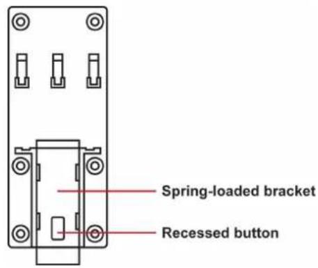
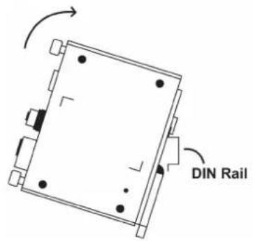
STEP 2: Insert the top of the DIN rail into the top slots on the DIN rail attachment plate.
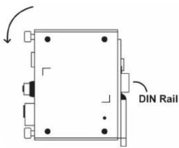
STEP 3: The DIN rail attachment unit will snap into place as shown in the illustration below.
Removing the ioPAC 8500 from a DIN Rail
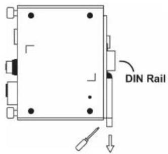
To remove the ioPAC 8500 from a DIN rail, use a screwdriver to push down the spring-loaded bracket until it locks in place, as shown in the diagram at the right. Next, rotate the bottom of the switch upwards and then remove the switch from the DIN rail.
Module Installation Procedure (Power-Off)
Moxa's ioPAC 8500 controllers come with 2, 5, or 9 slots for 85M-series modules. Use the following procedure to install modules when your system is powered off.
Step1: Install the module into the ioPAC 8500 system. The module's PCB should align with the edge of the frame. Push the module into the slot and make sure the module is plugged into the backplane.
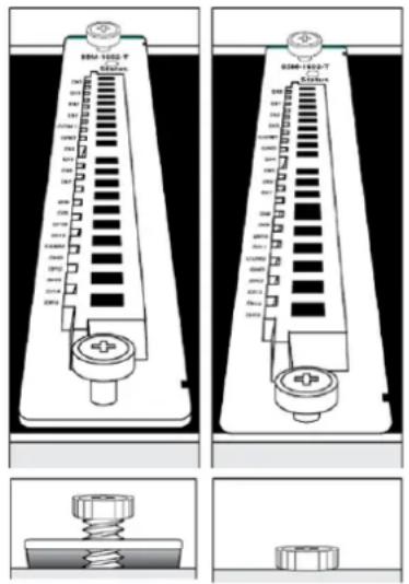
Step2: Fasten the two screws using 3.5 ± 0.5 kg of torque.
Module Installation Procedure (Power-On)
All ioPAC 8500 modules are hot-swappable, which means that you can safely install, remove, and replace modules while the system is powered on. When a module is removed or installed when the system is powered on, the module head stops processing and registers the newly installed or recently removed module, and scans for a configuration change. There is no disruption to normal operation during module insertion or removal.
After installing a new module, it could take about ten seconds for the system to recognize and activate the module, at which point the module's LED will turn green.

WARNING
When the system is powered on, do not install more than one module at a time. If you need to install multiple modules, wait until the most recently installed module's LED turns GREEN before installing the next module.
Configuring Power
Powering on the ioPAC Controller
The ioPAC controller can receive power from a 9 to 48 VDC power source, and is compliant with EN 50155 at 24 VDC. Input power is applied to the positive (V+) and negative (V-) terminals on the connector.
- When the input voltage is below the minimum recommended voltage the ioPAC will turn off.
- The ioPAC has reverse protection and power input over-voltage protection, allowing it to resist a maximum voltage of 60 V, and the ioPAC's power input over-current fuse protection specification is 5 A.
After connecting the Moxa ioPAC controller to the power supply, it will take 30 to 60 seconds for the operating system to boot up. The green Ready LED will illuminate continuously until the operating system is ready.
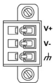

ATTENTION
This product is intended to be supplied by a Listed Power Unit with output marked "LPS" and rated for 9-48 VDC (minimum requirements). For railway rolling stock applications, these devices must be supplied by a galvanic isolated power supply with design based on the EN 50155 standard.
Grounding the ioPAC
For most applications, it is desirable to ground the system by connecting the system's power supply common wire to the chassis or panel ground. The negative (-V) side of the DC power input terminal as well as all I/O point terminals labeled GND are connected to chassis ground.
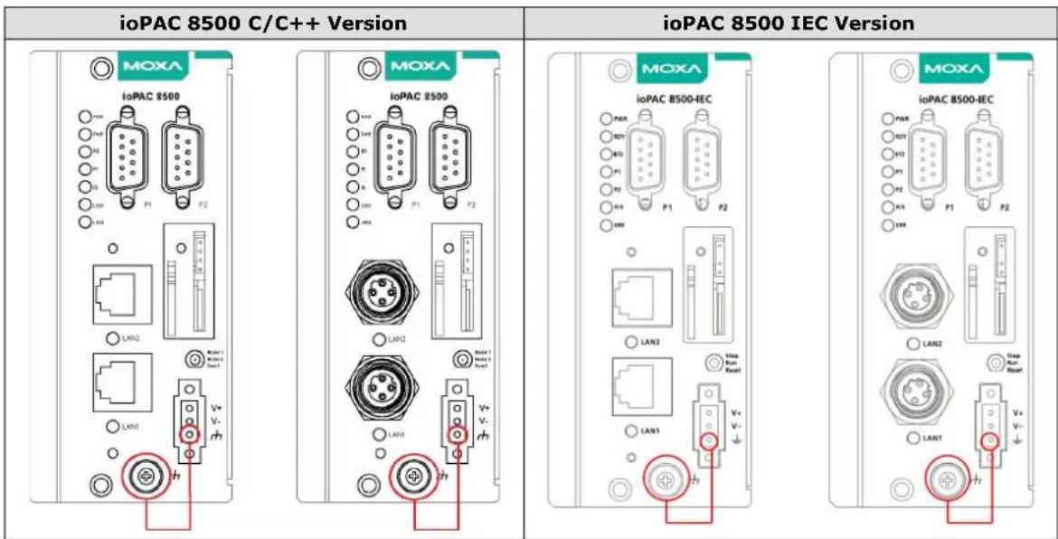
NOTE
-
Use 18 AWG wire for the power ground.
-
Grounding the device through the earth/ground pin ( ↓ ) gives 6kV ESD protection.
Installing a microSD Card
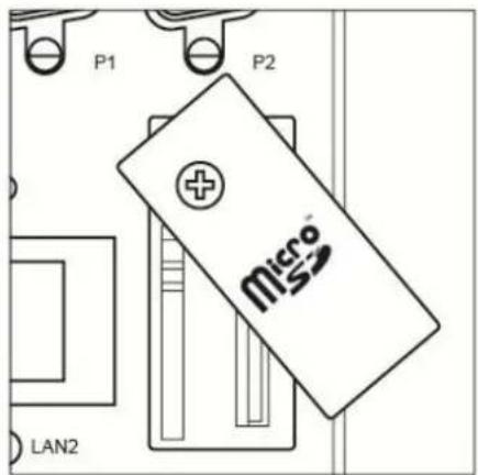
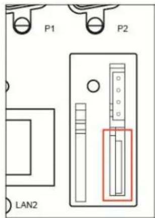
The ioPAC is equipped with one slot for a microSD card. The card reader slot is located inside the ioPAC device, so you will need to unscrew and remove the card cover to install your microSD card. When inserting a microSD card, remember to keep the front edge of the card facing down.
Follow these steps to remove or install a microSD card:
- Remove the screw holding the card cover in place.
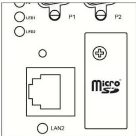
- (a) Insert the microSD card into the microSD card slot, or (b) Remove the microSD card from the microSD card slot.
natural_image
Blank white image with no visible content, text, or symbols- Fasten back the screw holding the card cover in place.
Connecting to the Network
Ethernet Communication
Connections to the LAN port are made through an RJ45 or M12 connector on the module. The wiring and pin connections for these connectors are described in separate sections below.
- TCP/IP Settings: Dual Speed Functionality: The ioPAC 8500's Ethernet ports auto negotiate with the connected devices and then use the fastest data transmission rate supported by both devices. The following table shows the TCP/IP parameters supported by the LAN port. Default values are set when a Factory Reset is performed on the controller.
| Lan Port 1 Lan Port 2 | |||
| Parameter | Supported Values | Parameter | Supported Values |
| IP Address | Default: 192.168.127.254 | IP Address | Default: 192.168.126.254 |
| Subnet Mask | Default: 255.255.255.0 | Subnet Mask | Default: 255.255.255.0 |
| Gateway | Default: 0.0.0.0 | Gateway | Default: 0.0.0.0 |
IP Address is the IP address of the controller.
Subnet Mask determines the subnet on which the controller is located.
Gateway determines how your controller communicates with devices outside its subnet. Enter the IP address of the gateway.
The IP address, subnet mask, and gateway are static; contact your network administrator to obtain these addresses for the controller.
RJ45 Ethernet Connector
The ideal maximum cable length of a 10/100BaseT connection is 100 m (350 feet), but the actual limit could be longer or shorter depending on the amount of electrical noise in the environment. To minimize the amount of noise, Ethernet cables should not run parallel to power cables or other types of cables that generate electrical noise.
The following diagram and table shows the pin connections for the RJ45 Ethernet connector:
RJ45 Connector Pin Assignment
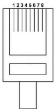
| Contact Media Direct Interface Signal | |
| 1 Tx + | (transmit) |
| 2 Tx - | (transmit) |
| 3 Rx + | (receive) |
| 4 Not used | |
| 5 Not used | |
| 6 Rx - | (receive) |
| 7 | Not used |
| 8 Not used | |
M12 Ethernet Connector
The ioPAC 8500 has two 10/100BaseT(X) Ethernet ports that use 4-pin shielded M12 connectors with D coding. The 10/100T(X) ports located on the front panel of ioPAC 8500 are used to connect to Ethernet-enabled devices. Most users configure these ports for Auto MDI/MDI-X mode, in which case the port's pinouts are adjusted automatically depending on the type of Ethernet cable used (straight-through or cross-over), and the type of device (NIC-type or HUB/Switch-type) connected to the port.
- The Auto MDI/MDI-X function (M12 connector) allows users to connect the ioPAC 8500's 10/100BaseTX ports to any kind of Ethernet device, without needing to pay attention to the type of Ethernet cable being used for the connection. This means that you can use either a straight-through cable or cross-over cable to connect the ioPAC 8500 to Ethernet devices.
The following diagram and table shows the pin connections for the M12 Ethernet connector:
M12 Ethernet Connector Pin Assignments
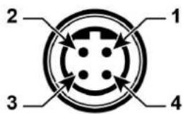
| Male | Wire-Color Bus | Reference | |
| 1 | Orange (+) B | ||
| 2 | Not used n.c - | ||
| 3 | - Shield S | ||
| 4 | Blue -1 | A |
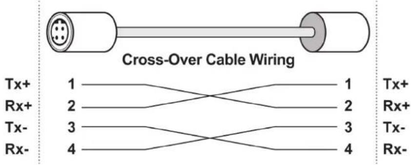
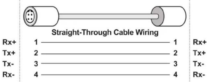
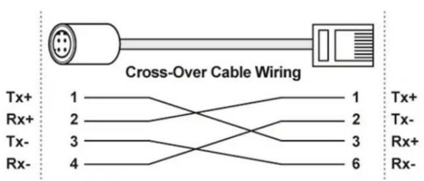
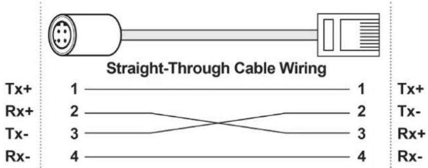
In what follows, we give pinouts for both MDI (NIC-type) ports and MDI-X (HUB/Switch-type) ports. We also give cable wiring diagrams for straight-through and cross-over Ethernet cables.
M12 (4-pin, M) to M12 (4-pin, M) Cross-Over Cable Wiring
M12 (4-pin, M) to M12 (4-pin, M) Straight-Through Cable Wiring
M12 (4-pin, M) to RJ45 (8-pin) Cross-Over Cable Wiring
M12 (4-pin, M) to RJ45 (8-pin) Straight-Through Cable Wiring

ATTENTION
Configuring the two LAN ports on the same ioPAC RTU controller to the same network domain (e.g., 192.168.1.1 and 192.168.1.2) is not recommended.
Port Trunking
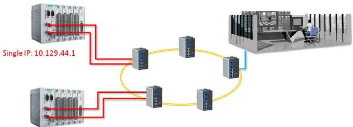
The ioPAC 8500 RTU controller has a Port Trunking function (active backup mode) that can convert two LAN-port IP addresses into one virtual IP address for easy SCADA integration and Ethernet redundancy. In the following diagram, both LAN ports on each ioPAC RTU controller are connected to a managed switch on an Ethernet network running SCADA software. For more details regarding configuration setup, refer to the ioPAC RTU Software User's Manual.
flowchart
graph TD
    A["Single IP: 10.129.44.1"] --> B["Device 1"]
    A --> C["Device 2"]
    A --> D["Device 3"]
    A --> E["Device 4"]
    B --> F["Router"]
    C --> F
    D --> F
    E --> F
    F --> G["Server"]
    style A fill:#f9f,stroke:#333
    style G fill:#ccf,stroke:#333
Single IP: 10.129.44.2
Serial Connectivity
Connecting to a Serial Device
The ioPAC RTU is equipped with two 3-in-1 serial ports that support RS-232/422/485, making it more convenient to connect field serial devices.
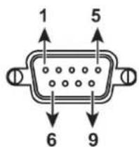
| Pin | RS-232 | RS-422 and 4-wire RS-485 | 2-wire RS-485 |
| 1 DCD | TxD-(A) | - | |
| 2 RXD | TxD+(B) | - | |
| 3 | TXD | RxD+(B) | Data+(B) |
| 4 | DTR | RxD-(A) | Data-(A) |
| 5 | GND | GND | GND |
| 6 DSR | - | - | |
| 7 | RTS | - | - |
| 8 CTS | - | - | |
| 9 RI | - | - |
Serial Console (Debug Port)
The serial console gives users a convenient way of connecting to the RTU controllers. This method is particularly useful when using the computer for the first time. The serial console is also effective for connecting the Moxa RTU controllers when you do not know target network settings and IP addresses.
Step 1: To use the serial console, remove the cover from the front/top panel first.
Console Port for the ioPAC Series
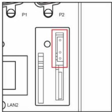
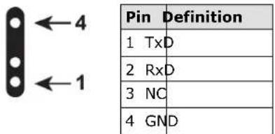
Step 2: Attach the 4-pin serial console cable to the console port. The following diagram shows the 4-pin serial connector and pin connections.
Pin Assignment for the Serial Console Port
Serial Console Default Settings
| Parameter Value | |
| Baudrate 115200 bps | |
| Parity None | |
| Data bits 8 | |
| Stop bits 1 | |
| Flow Control None | |
| Terminal VT100 |
We recommend using Moxa PComm Terminal Emulator to connect to the serial console. The following steps describe how to connect the console.
- Download Moxa PComm Lite from the Moxa website (www.moxa.com) or copy it from the following folder on the Documentation and Software CD: Software\utility\PComm.
- Install Moxa PComm Lite to the host Windows PC.
- Run PComm Lite Terminal Emulator from Start → Programs → PComm Lite Ver 1.x → Terminal Emulator.
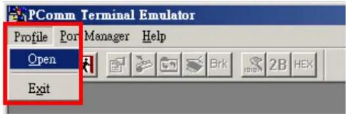
- Click Profile Open.
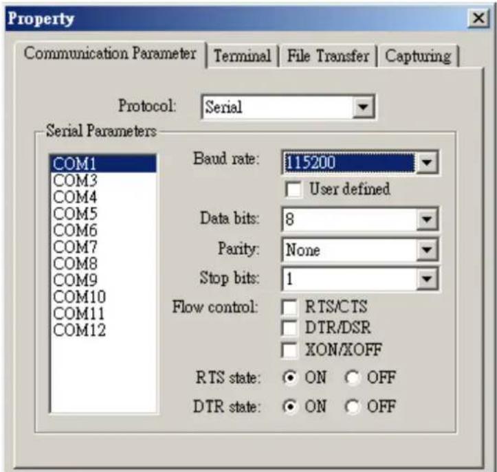
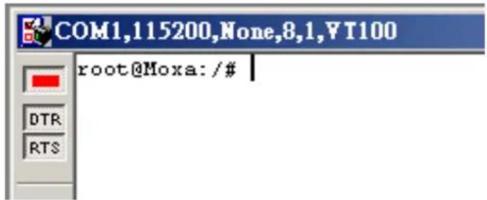
- Specify which COM port is connecting to the Moxa RTU, and use the following configuration settings: 115200, 8, none, 1.
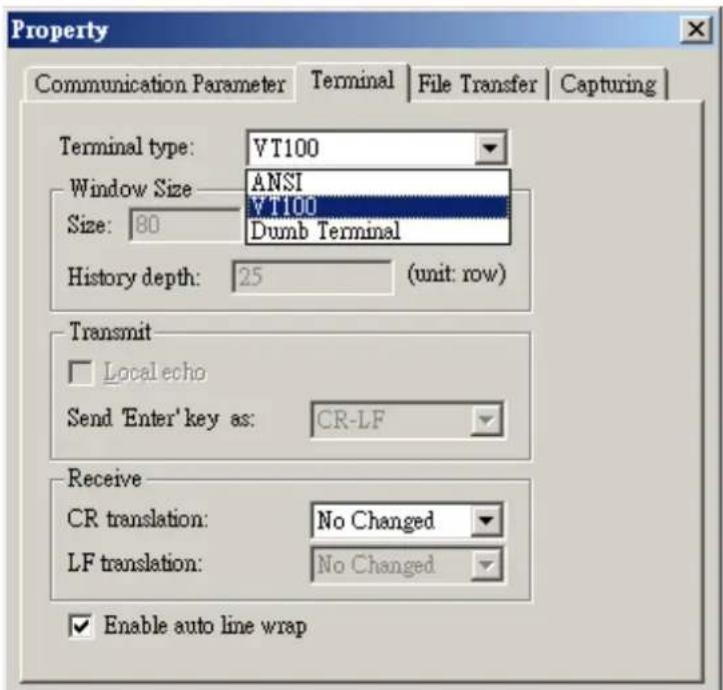
- Click on the Terminal tab and configure the Terminal Type to VT100. Click OK to proceed.
- The serial console will be displayed on the terminal screen.
Battery
The ioPAC RTU controller is equipped with one built-in, rechargeable VL2020 3V battery for the SRAM and one BR2032 3V non-rechargeable battery for the Real Time Clock (RTC).
• Rechargeable battery (VL2020) for SRAM
Sustains at least 1 week without power supply
Capacity: 20 mAh
Typical consumption (@ 25°C): 4 μA
5-year warranty
• Non-rechargeable battery (BR2032) for RTC
Sustains at least 5 years without power supply
➢ Capacity: 195 mAh
Typical consumption (@ 25°C): 2 μA
5-year warranty

Caution
Do NOT attempt to replace the battery. Contact your local dealer for replacement assistance.
This chapter introduces the ioPAC 8500's hardware specifications.
The following topics are covered in this chapter:
□ Appearance and Dimensions
Appearance
Dimensions
Hardware Block Diagrams
➢ ioPAC 8500 CPU Board Block Diagram
□ Product Hardware Specifications
Product Selection Guide
Specifications
☐ ioPAC 8500 LED Indicators
System LEDs
C/C++ Version LEDs: LED1 and LED2
IEC-61131-3 Compliant LEDs: R/S and ERR
➢ Communication LEDs
□ The Toggle Switch
In IEC-61131-3 Models
In C/C++ Models
☐ Toggle Switch: Factory Reset Process
Appearance and Dimensions
Appearance
ioPAC 8500 Modular Head
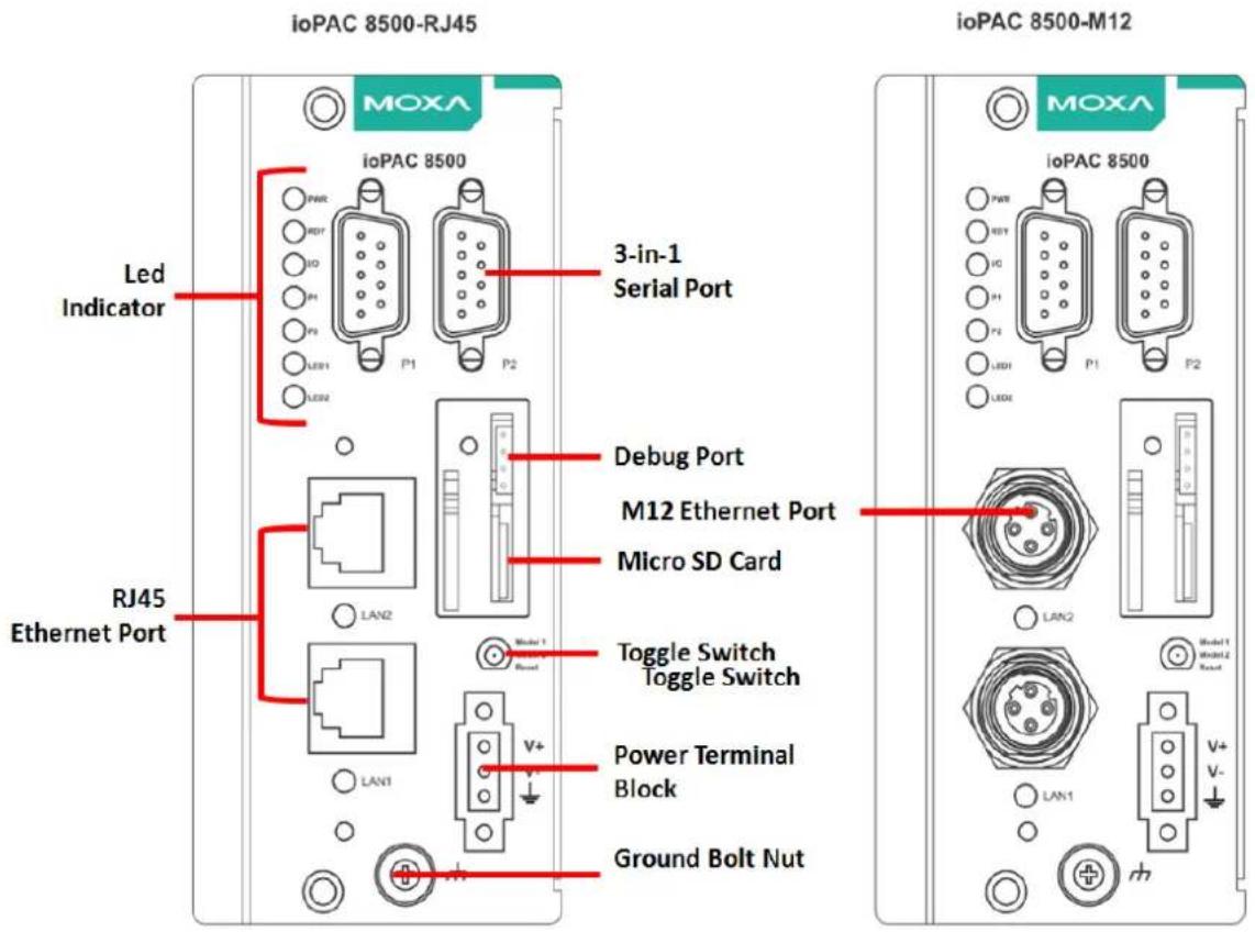
The following figures depict ioPAC 8500 modular heads. There are two types of modular heads, both have dual Ethernet ports but one is RJ45 and the other is M12.
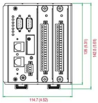
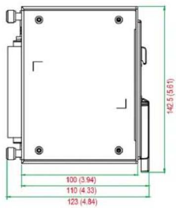
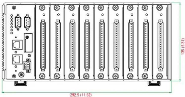
Dimensions (unit: mm(inch))
ioPAC 8500-2
ioPAC 8500-5

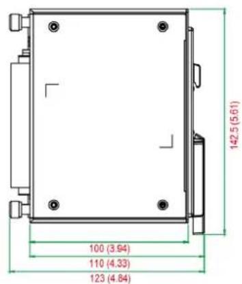
ioPAC 8500-9
natural_image
Front view of a rack-mounted industrial device with multiple ports and connectors (no text or symbols visible)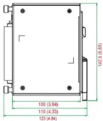
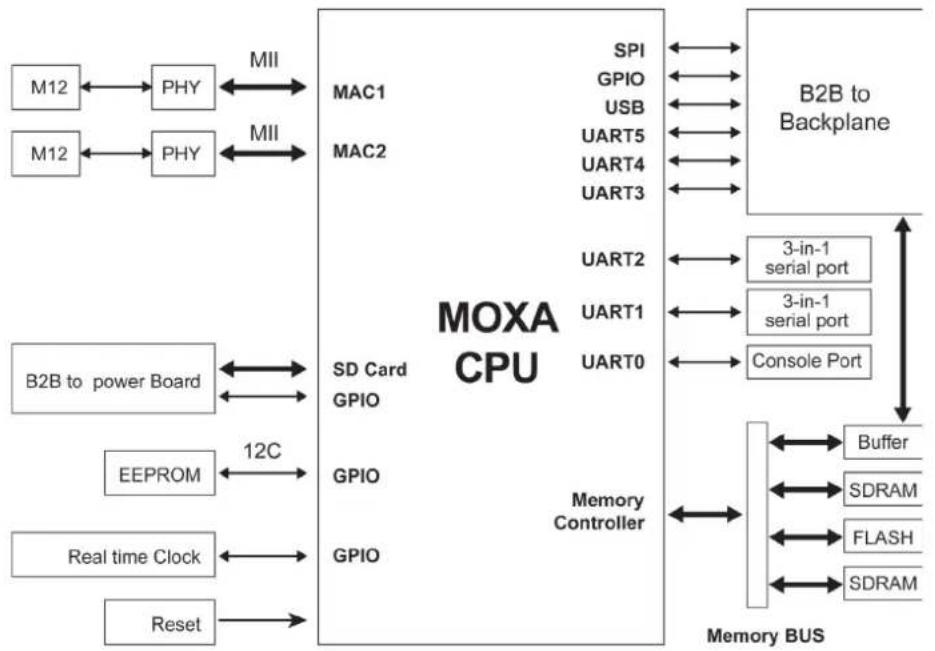
Hardware Block Diagrams
ioPAC 8500 CPU Board Block Diagram
flowchart
graph TD
    subgraph_MOXA_CPU["MOXA CPU"]
        M12 --> PHY1
        M12 --> PHY2
        PHY1 <--> MII1
        PHY2 <--> MII2
        M12 --> PHY3
    end

    subgraph_B2B_to_Backplane["B2B to Backplane"]
        SPI --> GPIO1
        GPIO --> USB
        UART5 --> UART4
        UART3 --> UART2
        UART2 --> UART1
        UART0 --> UART0
    end

    subgraph_Memory_BUS["Memory BUS"]
        Buffer --> SDRAM1
        Buffer --> SDRAM2
        Flash --> SDRAM1
        Flash --> SDRAM2
        SDRAM1 <--> Buffer
        SDRAM2 <--> Buffer
    end

    M12 --> PHY4
    M12 --> PHY5
    B2B_to_power_Board["B2B to power Board"] <--> SD_Card["SD Card GPIO"]
    EEPROM["EEPROM"] <--> 12C["12C"]
    Real_time_Clock["Real time Clock"] <--> GPIO_GPIO["GPIO"]
    Reset["Reset"] <--> GPIO_GPIO["GPIO"]
    Memory_Controller["Memory Controller"] --> UART0
    Memory_Controller --> UART1
    Memory_Controller --> UART2
    Memory_Controller --> UART3
    Memory_Controller --> UART4
    Memory_Controller --> UART5
    Memory_Controller --> UART6
    Memory_Controller --> UART7
    Memory_Controller --> UART8
    Memory_Controller --> UART9
    Memory_Controller --> UART10
    Memory_Controller --> UART11
    Memory_Controller --> UART12
    Memory_Controller --> UART13
    Memory_Controller --> UART14
    Memory_Controller --> UART15
    Memory_Controller --> UART16
    Memory_Controller --> UART17
    Memory_Controller --> UART18
    Memory_Controller --> UART19
    Memory_Controller --> UART20
Product Hardware Specifications
Product Selection Guide
| Model Name Description | |
| ioPAC 8500-2-RJ45-C-T | 2 slots, RJ45, C/C++ |
| ioPAC 8500-5-RJ45-C-T | 5 slots, RJ45, C/C++ |
| ioPAC 8500-9-RJ45-C-T | 9 slots, RJ45, C/C++ |
| ioPAC 8500-2-M12-C-T | 2 slots, M12, C/C++ |
| ioPAC 8500-5-M12-C-T | 5 slots, M12, C/C++ |
| ioPAC 8500-9-M12-C-T | 9 slots, M12, C/C++ |
| ioPAC 8500-2-RJ45-IEC-T | 2 slots, RJ45, IEC |
| ioPAC 8500-5-RJ45-IEC-T | 5 slots, RJ45, IEC |
| ioPAC 8500-9-RJ45-IEC-T | 9 slots, RJ45, IEC |
| ioPAC 8500-2-M12-IEC-T | 2 slots, M12, IEC |
| ioPAC 8500-5-M12-IEC-T | 5 slots, M12, IEC |
| ioPAC 8500-9-M12-IEC-T | 9 slots, M12, IEC |
NOTE Conformal coating available on request.
Specifications
Computer
Main CPU: ARM9 based CPU, 32-bit/192 MHz
I/O CPU: ARM Cortex M4 based CPU, 32-bit/80MHz
OS: Linux
Clock: Real-time clock with battery backup
Memory:
- SDRAM: 64 MB
- Flash: 32 MB
• SRAM: 256 KB (battery backup lasts for 1 week) - microSD™ Slot: Up to 32 GB (SD 2.0 compatible)
Note: For units operating in extreme temperatures, industrial grade, wide-temperature microSD cards are required.
Backplane Bus Speed: Up to 200 Mbps for all slots
Ethernet Interface
LAN: 2 x 10/100 Mbps, 2 MACs (IPs), RJ45 or M12
Protection: 1.5 kV magnetic isolation
Serial Communication
Interface:
• 2 RS-232/422/485 ports, software selectable (DB9 male)
• 1 RS-232 debug port (4-pin connector)
Serial Line Protection: 8 kV ESD for all signals
Serial Communication Parameters
Parity: None, Even, Odd
Data Bits: 7, 8
Stop Bits: 1, 2
Flow Control: RTS/CTS, XON/XOFF
Baudrate: 300 bps to 921.6 Kbps
Serial Signals
RS-232: TxD, RxD, DTR, DSR, RTS, CTS, DCD, GND
RS-422: Tx+, Tx-, Rx+, Rx-, GND
RS-485-4w: Tx+, Tx-, Rx+, Rx-, GND
RS-485-2w: Data+, Data-, GND
Software Characteristics
Automation Languages: C/C++, IEC 61131-3
Protocols: Modbus/TCP, Modbus/RTU Master, Modbus/RTU Slave
Power Requirements
Power Input: 24 VDC nominal, 9 to 48 VDC
Note: Compliant with EN 50155 at 24 VDC
Current for I/O Modules: 5 A @ 3.3 VDC (max.)
Power Consumption: 3.65 W @ 24 VDC
Physical Characteristics
Housing: Aluminum
Dimensions:
- 2-slot version: 114.7 × 135 × 100 ~mm (4.52 x 5.31 x 3.94 in)
- 5-slot version: 190.9 × 135 × 100 ~mm (7.52 x 5.31 x 3.94 in)
- 9-slot version: 292.5 × 135 × 100 ~mm (11.52 x 5.31 x 3.94 in)
Weight:
• 2-slot version: 1300 g
- 5-slot version: 2000 g
• 9-slot version: 2575 g
Mounting: DIN rail mounting (standard), wall mounting (optional)
Connector: Spring-type terminal block
Environmental Limits
Operating Temperature: -40 to 75°C (-40 to 176°F)
Storage Temperature: -40 to 85°C (-40 to 185°F)
Ambient Relative Humidity: 5 to 95% (non-condensing)
Altitude: Up to 2000 m
Note: Please contact Moxa if you require products guaranteed to function properly at higher altitudes.
Standards and Certifications
Safety: UL 508 (Pending)
EMI: EN 55022, EN 61000-3-2; EN 61000-3-3; FCC Part 15 Subpart B Class A
EMS: EN 55024, EN 61000-4-2, EN 61000-4-3, EN 61000-4-4, EN 61000-4-5, EN 61000-4-6, EN 61000-4-8, EN 61000-4-11
Shock: IEC 60068-2-27
Freefall: IEC 60068-2-32
Vibration: IEC 60068-2-6
Rail Traffic: EN 50155, EN 50121-3-2, EN 50121-4
Note: Please check Moxa's website for the most up-to-date certification status.
MTBF (mean time between failure)
Time: 859,979 hrs
Database: Telcordia (Bellcore)
Warranty
Warranty Period: 5 years
Details: See www.moxa.com/warranty
ioPAC 8500 LED Indicators
There are 9 LEDs on the ioPAC controller.
ioPAC 8500 C/C++ Version
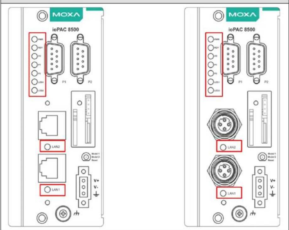
ioPAC 8500 C/C++ Version
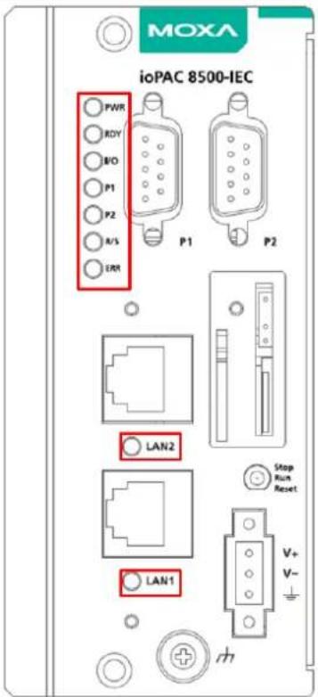
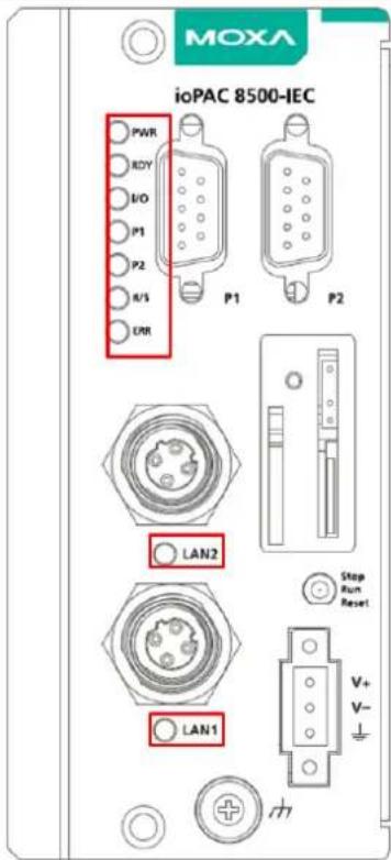
| Category | Label | Usage | |
| System | PWR | System Power | On: Power OnOff: Power Off |
| RDY System (Kernel)Ready | Green: System ReadyBlinking Green: System is booting upRed: System error, firmware upgrade, or reset procedure underwayBlinking Red: Factory reset triggered | ||
| I/O Expansion | Status(on Head) | Green: Expansion configuration OKRed: Expansion configuration failedOff: No module connected | |
| Status Expansion | Status(on Module) | Green: Expansion mode readyRed: Expansion mode failedOff: Not connected | |
| C/C++ Version | LED1, LED2 | User-Defined | User-Defined |
| IEC Version | R/S | Run/Stop Mode | Green: The CPU is executing PRDK.OFF: The CPU has stopped / is not executing PRDK. |
| ERR | Error | Red: System / I/O / services errorOFF: No error (auto update if error fixes) | |
| Communication | LAN1, LAN2 | EthernetConnection | Green: 100MbAmber: 10MbBlinking: data transmittingOff: disconnected |
| P1, P2 Serial | Connection | Green: Transmitting data (Tx)Amber: Receiving data (Rx)Off: disconnected | |
System LEDs
PWR (Power LED)
The Power (PWR) LED indicates the status of the system power. When the system is on, this LED will turn green, and when the system power is off this LED will be off.
RDY (Ready LED)
The Ready (RDY) LED indicates the status of the system's kernel. When the LED is green the system kernel is ready. When the LED is green and blinking, the system's kernel is booting-up. When the Ready (RDY) LED is red, there is either a system error or the system is being reset to factory defaults. When the Ready LED is red and blinking, the device's factory default mode has been triggered.
IO (Expansion Module LED)
The IO LED on the module indicates the status of the expansion modules. When the LED is green, all expansion module configurations are okay, and when the LED is red, at least one of the expansion modules failed to configure properly.
C/C++ Version LEDs: LED1 and LED2
The ioPAC controller allows the user to custom configure these two LEDs (through the software interface). Refer to the C/C++ Sample Code Programming Guide for ioPAC RTU Controllers for details.
IEC-61131-3 Compliant LEDs: R/S and ERR
The ioPAC controller supports IEC-61131-3-compliant Run/Stop and Error (ERR) LEDs for ISaGRAF-specific notifications. These LEDs are not user configurable.
Communication LEDs
P1 and P2
The ioPAC controller comes with two serial connections. P1 and P2 represent the status of each serial connection. When the LED is green, the ioPAC is transmitting data (Tx). When the LED is amber, the ioPAC is receiving data (Rx). When the LED is blinking randomly, data is either being transmitted or received. For example, if P1 is blinking and is green, the ioPAC is transmitting data.
When the LED is off, the serial connection is disconnected.
LAN1 and LAN2
The ioPAC controller comes with two Ethernet ports, with the LAN1 and LAN2 LEDs used to represent the status of the two connections. When the LED is green, data is transmitting at 100 Mbps. When the LED is amber, data is transmitting at 10 Mbps. When the LED is blinking, data is being transmitted. When the LED is off, there is no Ethernet connection, or the Ethernet connection has been disconnected.
The Toggle Switch
The toggle switch functions differently depending on the programming language set your ioPAC model is configured for.
In IEC-61131-3 Models
For IEC-61131-3 models, the toggle switch is a simple run/stop switch for IEC programs. Users can enable or disable it through RTUxpress. The default setting is disabled.
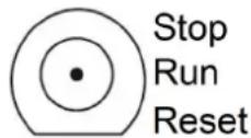
In C/C++ Models
On models that use the C language set, the toggle switch is programmable, giving integrators and end-users a switch that can trigger one of two operation modes (refer to the C/C++ Sample Code Programming Guide for ioPAC RTU Controllers for details).
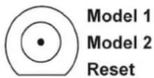
Toggle Switch: Factory Reset Process
Use the following procedure to reset the ioPAC to the factory defaults. Note that when you reset the ioPAC, all of your tag definitions, software programs, and files will be deleted, and the service and runtime engine will be restarted.
- When the system is booting up and the RDY LED is blinking GREEN, hold the toggle switch in the "reset" position.
- Continue to hold toggle switch until the "RDY" LED turns a solid RED, and then release the toggle switch. It will take around 90 seconds to complete the factory reset process.
- When the "RDY" LED starts blinking GREEN (indicating that the kernel is rebooting), the factory mode is completed.
NOTE Do NOT power off, operate, or connect any devices when the RDY LED is a solid red. The factory reset function is only activated when the system is booting up.
In this chapter, we provide the 85M modules' specifications.
The following topics are covered in this chapter:
☐ 85M Module Descriptions
□ Common Specifications
☐ Module Specifications
➢ 85M-1602-T: Digital Input, 24 VDC, Sink/Source, Dry Contact
85M-2600-T: Digital Output, 24 VDC, Sink Type
85M-38XX-T: Analog Input
85M-6600-T: RTD
85M-6810-T: Thermocouple
85M-5401-T: Serial Ports
85M Module Descriptions
The ioPAC 8500 controllers support the following modules.
| Model Name Description | |
| 85M-1602-T 16 DI, Sink/Source | |
| 85M-2600-T 16 DO, Sink | |
| 85M-3800-T | 8 AI, 4-20 mA |
| 85M-3810-T | 8 AI, 0-10 V |
| 85M-3801-T | 8 AI 40 KHz, 4-20 mA |
| 85M-3811-T | 8 AI 40 KHz, 0-10 V |
| 85M-6600-T | 6 RTD |
| 85M-6810-T 8 TC | |
| 85M-5401-T 4 Serial Ports | |
NOTE Conformal coating available on request.
Common Specifications
The following are specifications common to all ioPAC 8500 modules.
Environmental Limits
Storage Temperature: -40 to 85°C (-40 to 185°F)
Ambient Relative Humidity: 5 to 95% (non-condensing)
Standards and Certifications
Safety: UL 508 (Pending)
EMI: EN 55022, EN 61000-3-2, EN 61000-3-3,
FCC Part 15 Subpart B Class A
EMS: EN 55024, EN 61000-4-2, EN 61000-4-3,
EN 61000-4-4, EN 61000-4-5, EN 61000-4-6,
EN 61000-4-8, EN 61000-4-11
Shock: IEC 60068-2-27
Freefall: IEC 60068-2-32
Vibration: IEC 60068-2-6
Rail Traffic: EN 50155, EN 50121-3-2, EN 50121-4
Note: Please check Moxa's website for the most up-to-date certification status.
Warranty
Warranty Period: 5 years
Details: See www.moxa.com/warranty
Module Specifications
85M-1602-T: Digital Input, 24 VDC, Sink/Source, Dry Contact
The 85M-1602-T modules is a 16-channel, sink/source, or dry contact type digital input module that support wide temperature and high isolation protection.
Block Diagram
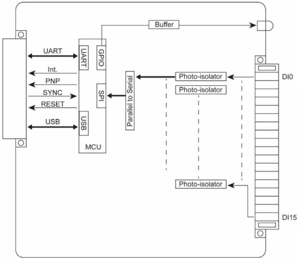
The following is the 85M-1602-T module's block diagram. The MCU has two communication interfaces: USB and UART. The 85M-1602-T communicates with the modular head through USB and UART interfaces. The MCU accesses the I/O information by SPI through the parallel-to-serial chip. The 85M-1602-T module has isolation protection up to 3K VDC or 2K Vrms, and photo isolators between the I/O channels and the MCU.
flowchart
graph TD
    A["Device"] -->|UART| B["PCI"]
    A -->|Int.| B
    A -->|PNP| B
    A -->|SYNC| B
    A -->|RESET| B
    A -->|USB| B
    B --> C["MCU"]
    C --> D["Parallel to Serial"]
    D --> E["Buffer"]
    E --> F["DI0"]
    D --> G["Photo-isolator"]
    G --> H["DI15"]
    D --> I["Photo-isolator"]
    I --> H
    style A fill:#f9f,stroke:#333
    style F fill:#ccf,stroke:#333
Specifications
The following are the 85M-1602-T module's product specifications.
Inputs and Outputs
Digital Inputs: 16 channels
Isolation: 3K VDC or 2K Vrms
Digital Inputs
Sensor Type: Wet contact (NPN or PNP), dry contact
I/O Mode: DI or event counter
Dry Contact:
- On: short to GND
- Off: open
Wet Contact (DI to GND):
NPN (DI to GND):
- On: 0 to 3 VDC
- Off: 10 to 30 VDC
PNP (DI to GND):
- Off: 0 to 3 VDC
- On: 10 to 30 VDC
Common Type: 8 points per COM
Counter Frequency: 5 kHz
Digital Filtering Time Interval: Software selectable unit: 0.1 ms
Physical Characteristics
Wiring: I/O cable, max. 16 AWG
Connector: Spring type terminal block
Environmental Limits
Operating Temperature: -40 to 75°C
Power Requirements
Power Consumption: 1.2 W @ 3.3 VDC
MTBF (mean time between failure)
Time: 1,132,561 hrs
Database: Telcordia (Bellcore)
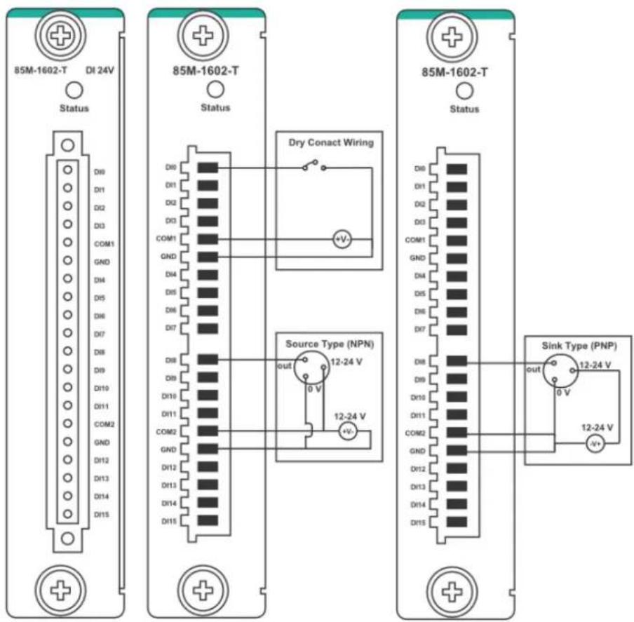
Pin Assignment and Wiring Guide
The following is 85M-1602-T module's pin assignment and wiring guide.
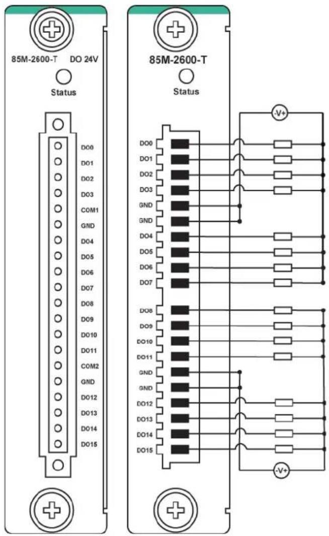
85M-2600-T: Digital Output, 24 VDC, Sink Type
The 85M-2600-T features sink type sixteen digital output channels. The 85M-2600-T can use the module's digital outputs to determine the state of limit or safety switches, or to receive remote digital signals.
Block Diagram
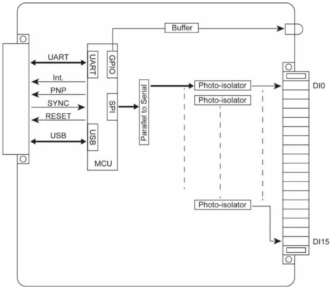
The following is the 85M-2600-T module's block diagram. The MCU has two communication interfaces, USB and UART, which the 85M-2600-T uses to communicate with the modular head. The MCU accesses information from the I/O channels by SPI through the parallel-to-serial chip. 85M-2600-T has isolation protection up to 3K VDC or 2K Vrms, and photo-isolators between the I/O channels and the MCU.
flowchart
graph TD
    A["Block"] -->|UART| B["UART"]
    A -->|INT.| C["GPIO"]
    A -->|PNP| D["SPI"]
    A -->|SYNC| E["Multi-Channel"]
    A -->|RESET| F["Multi-Channel"]
    A -->|USB| G["Multi-Channel"]
    B --> H["MCU"]
    C --> H
    D --> H
    E --> H
    F --> H
    G --> H
    H --> I["Parallel to Serial"]
    I --> J["Photo-isolator"]
    I --> K["Photo-isolator"]
    J --> L["DI0"]
    K --> M["DI15"]
    N["Buffer"] --> O["Output"]
Specifications
The following are the 85M-2600-T module's product specifications.
Inputs and Outputs
Digital Outputs: 16 channels
Isolation: 3K VDC or 2K Vrms
Digital Outputs
Type: Sink
I/O Mode: DO or pulse output
Pulse Output Frequency: 5 kHz
Over-voltage Protection: 45 VDC
Over-current Protection: 2.6 A (4 channels @ 650 mA)
Over-temperature Shutdown: 175°C (typical), 150°C (min.)
Current Rating: 200 mA per channel
Physical Characteristics
Wiring: I/O cable, max. 16 AWG
Connector: Spring type terminal block
Environmental Limits
Operating Temperature: -40 to 75°C
Power Requirements
Power Consumption: 0.85 W @ 3.3 VDC
MTBF (mean time between failure)
Time: 792,571 hrs
Database: Telcordia (Bellcore)
Pin Assignment and Wiring Guide
85M-38XX-T: Analog Input
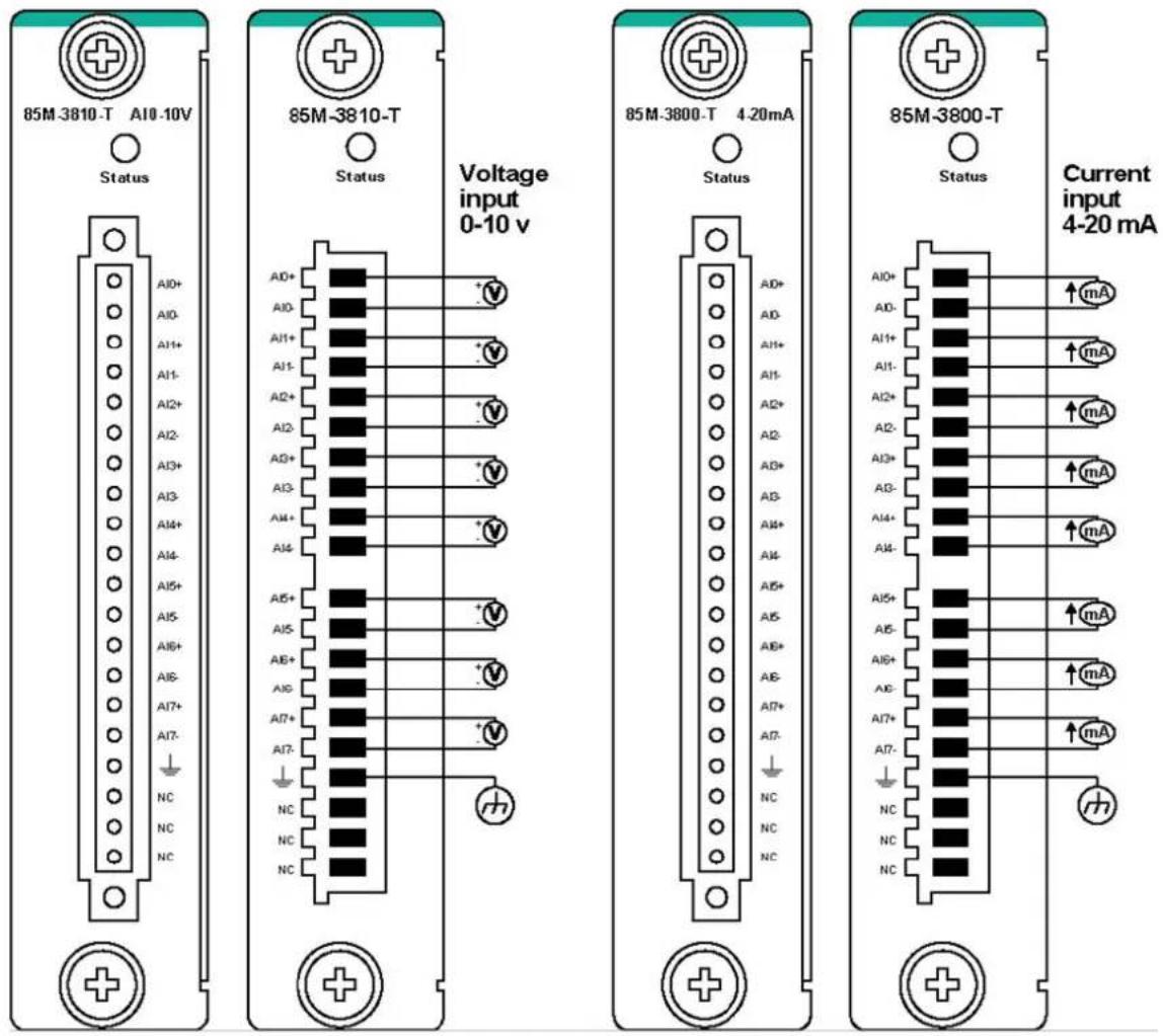
The 85M-38XX-T series provides eight 16-bit analog input modules. It accepts voltage inputs (0–10 V) and current input (4–20 mA). This high performance analog input module features high density I/O with a flexible topology and hot-swappable functionality. This module is cost-effective solution for most industrial application.
Block Diagram
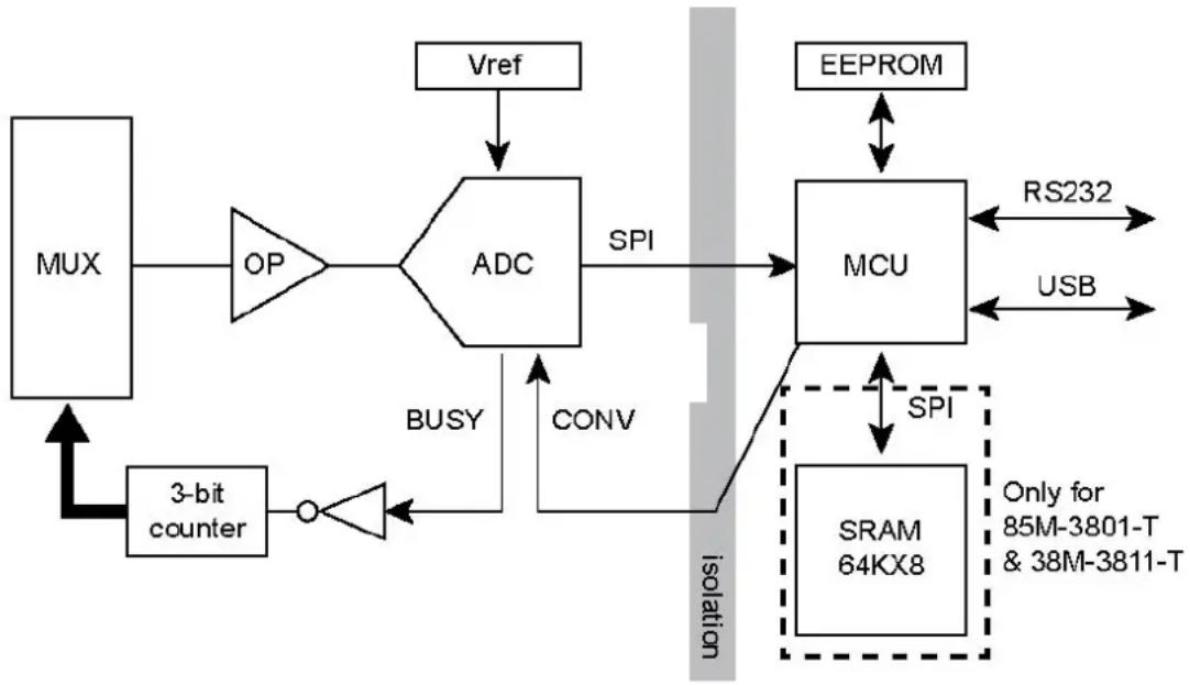
The following is the 85M-38XX-T module's block diagram. The 85M-38XX-T uses an MCU processor that has three communication interfaces: SPI, RS232, and USB. The MCU processor accesses the ADC and SRAM by SPI, whereas the 85M-38XX-T module communicates with the modular head through RS-232 and USB interfaces. The 85M-38XX-T has isolation protection up to 3K VDC or 2K Vrms.
flowchart
graph TD
    A["MUX"] --> B["OP"]
    B --> C["ADC"]
    C --> D["MCU"]
    D --> E["SRAM 64KX8"]
    E --> F["EEPROM"]
    F --> G["Vref"]
    G --> C
    C --> H["BUSY"]
    H --> I["CONV"]
    I --> J["3-bit counter"]
    J --> K["+"]
    K --> A
    style C fill:#f9f,stroke:#333
    style D fill:#ccf,stroke:#333
    style E fill:#cfc,stroke:#333
    style F fill:#fcc,stroke:#333
    style G fill:#cff,stroke:#333
    style H fill:#ffc,stroke:#333
    style I fill:#cfc,stroke:#333
    style J fill:#fcc,stroke:#333
    style K fill:#ffc,stroke:#333
    style_L["RS232"] <--> F
    M["USB"] <--> F
    N["Only for 85M-3801-T & 38M-3811-T"] <--> E
    O["isolation"] --> P["SP1"]
    P --> C
Specifications
The following are the 85M-38XX-T module's product specifications.
85M-3800-T: 8 analog inputs, 4 to 20 mA Specifications
Inputs and Outputs
Analog Inputs: 8 channels
Isolation: 3K VDC or 2K Vrms
Analog Inputs
Type: Differential
Resolution: 16 bits
I/O Mode: 4 to 20 mA (wire off)
Accuracy:
±0.1% FSR @ 25°C
±0.3% FSR @ -40 and 75°C
Sampling Rate:
- All channels: 100 samples/sec
• Per channel: 12.5 samples/sec
Input Impedance: 125 ohms (min.)
Physical Characteristics
Wiring: I/O cable, max. 16 AWG
Connector: Spring type terminal block
Environmental Limits
Operating Temperature: -40 to 75°C
Power Requirements
Power Consumption: 1.05 W @ 3.3 VDC
MTBF (mean time between failure)
Time: 1,512,906 hrs
Database: Telcordia (Bellcore)
85M-3801-T: 8 analog inputs, 4 to 20 mA, 40 kHz Specifications
Inputs and Outputs
Analog Inputs: 8 channels
Isolation: 3K VDC or 2K Vrms
Analog Inputs
Type: Differential
Resolution: 16 bits
I/O Mode: 4 to 20 mA (wire off)
Historical Data Buffering: Up to 6 sec per channel
Accuracy:
±0.1% FSR @ 25°C
±0.3% FSR @ -40 and 75°C
Sampling Rate:
• All channels: 40k samples/sec
• Per channel: 5k samples/sec
Input Impedance: 125 ohms (min.)
Physical Characteristics
Wiring: I/O cable, max. 16 AWG
Connector: Spring type terminal block
Environmental Limits
Operating Temperature: -40 to 75°C
Power Requirements
Power Consumption: 1.25 W @ 3.3 VDC
MTBF (mean time between failure)
Time: 1,410,655 hrs
Database: Telcordia (Bellcore)
85M-3810-T: 8 analog inputs, 0 to 10 VDC Specifications
Inputs and Outputs
Analog Inputs: 8 channels
Isolation: 3K VDC or 2K Vrms
Analog Inputs
Type: Differential
Resolution: 16 bits
I/O Mode: 0 to 10 VDC
Accuracy:
±0.1% FSR @ 25°C
±0.3% FSR @ -40 and 75°C
Sampling Rate:
- All channels: 100 samples/sec
• Per channel: 12.5 samples/sec
Input Impedance: 200 k-ohms (min.)
Physical Characteristics
Wiring: I/O cable, max. 16 AWG
Connector: Spring type terminal block
Environmental Limits
Operating Temperature: -40 to 75°C
Power Requirements
Power Consumption: 1.04 W @ 3.3 VDC
MTBF (mean time between failure)
Time: 1,530,690 hrs
Database: Telcordia (Bellcore)
85M-3811-T: 8 analog inputs, 0 to 10 VDC, 40 kHz Specifications
Inputs and Outputs
Analog Inputs: 8 channels
Isolation: 3K VDC or 2K Vrms
Analog Inputs
Type: Differential
Resolution: 16 bits
I/O Mode: 0 to 10 VDC
Historical Data Buffering: Up to 6 sec per channel
Accuracy:
±0.1% FSR @ 25°C
±0.3% FSR @ -40 and 75°C
Sampling Rate:
• All channels: 40k samples/sec
• Per channel: 5k samples/sec
Input Impedance: 20 M-ohms (min.)
Physical Characteristics
Wiring: I/O cable, max. 16 AWG
Connector: Spring type terminal block
Environmental Limits
Operating Temperature: -40 to 75°C
Power Requirements
Power Consumption: 1.25 W @ 3.3 VDC
MTBF (mean time between failure)
Time: 1,426,112 hrs
Database: Telcordia (Bellcore)
Pin Assignment and Wiring Guide
The following is the 85M-38XX-T module's pin assignment and wiring guide.
Analog Input Data Format
The I/O analog inputs have a 16-bit, unipolar, and analog to digital (A/D) converter that measures input voltages from 0–10 V and current from 4–20 mA (with Burnout). The following chart is the raw data conversion table for current and voltage.
The voltage ranges from 0 to 10 V. The lowest voltage of 0 V represents raw data of 0, and the highest voltage of 10 V represents raw data of 65535. When the raw voltage data is at 1, it represents 0.15 mV. The current ranges from 0 to 20 mA. The lowest current of 0 mA represents a raw data value of 0. Users can manually adjust the burnout value from 0 to 4 mA. All raw data below the burnout value will be 0. The highest current of 20 mA represents raw data of 65535. Raw current data of 1 represents 0.3125 μA.
Burnout mode can indicate if the current analog input has burned out.
NOTE Please refer to the ioPAC RTU Software User's Manual for the burnout mode settings.
NOTE
Grounding the device through the earth/ground pin (↓) gives 6kV ESD protection.
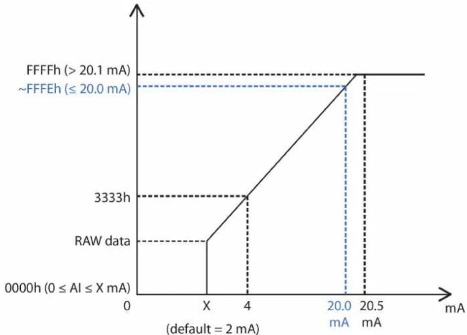
The 4–20 mA burnout mode values are defined in the following diagram:

Users can define burnout values for selected ranges. When input values are in the burnout range, raw data will register as 0000h to indicate analog input burnout. The definition of raw data is as follows:
| Burnout Value (BO) | 0.0 < BO < 4.0 | User-defined (default: 2 mA) |
| Burnout State | 0 ≤ AI < BO mA | S/W output 0000h |
| Under Range | BO ≤ AI < 4 mA | S/W output raw data |
| Normal Range | 4 ≤AI ≤ 20.00 mA | S/W output raw data until FFFEh |
| Over Range | XX > 20.00 mA | S/W output FFFFh |
line
| Current (mA) | Value | | ------------ | --------- | | 0 | 0 | | X | 3333 | | 4 | 3333 | | 20.0 | 20.1 | | 20.5 | 20.1 |Current
| Data Current | |
| 0 0 mA | |
| 1 0.3125 μA | |
| 13107 4 mA | |
| 49152 15 mA | |
| 65534 20 mA | |
| 65535 > 20 mA |
Voltage
| Data Voltage | |
| 0 0 V | |
| 1 0.16 mV | |
| 16384 2.5 V | |
| 32768 5 V | |
| 65535 10 V |
85M-6600-T: RTD
The 85M-6600-T module provides 6-channel RTD which features high density I/O with a flexible topology and hot-swappable functionality. This module is cost-effective solution for most industrial application.
Block Diagram
The following is the 85M-6600-T module's block diagram. The 85M-6600-T uses an MCU processor that has three communication interfaces: SPI, RS232, and USB. Whereas the 85M-6600-T module communicates with the modular head through RS-232 and USB interfaces. The 85M-6600-T has isolation protection up to 3K VDC or 2K Vrms.
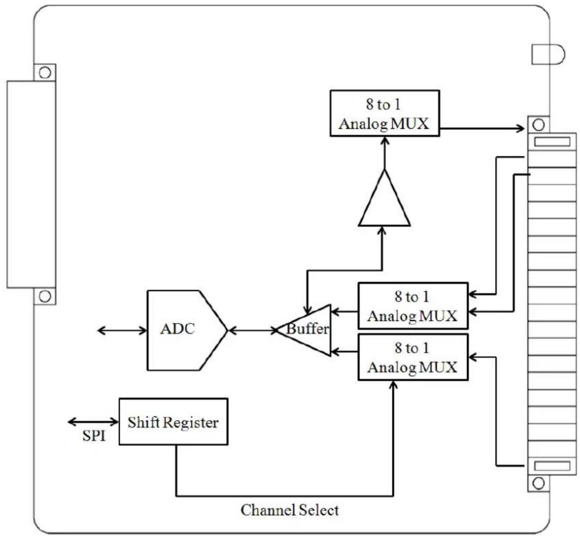
flowchart
graph TD
    A["ADC"] --> B["Buffer"]
    C["Shift Register"] --> B
    B --> D["8 to 1 Analog MUX"]
    D --> E["8 to 1 Analog MUX"]
    E --> F["8 to 1 Analog MUX"]
    F --> G["Channel Select"]
    G --> H["SPI"]
    H --> I["ADC"]
    I --> J["8 to 1 Analog MUX"]
    J --> K["8 to 1 Analog MUX"]
    K --> L["8 to 1 Analog MUX"]
    L --> M["8 to 1 Analog MUX"]
    M --> N["8 to 1 Analog MUX"]
    N --> O["8 to 1 Analog MUX"]
    O --> P["8 to 1 Analog MUX"]
    P --> Q["8 to 1 Analog MUX"]
    Q --> R["8 to 1 Analog MUX"]
    R --> S["8 to 1 Analog MUX"]
    S --> T["8 to 1 Analog MUX"]
    T --> U["8 to 1 Analog MUX"]
    U --> V["8 to 1 Analog MUX"]
    V --> W["8 to 1 Analog MUX"]
    W --> X["8 to 1 Analog MUX"]
    X --> Y["8 to 1 Analog MUX"]
    Y --> Z["8 to 1 Analog MUX"]
    Z --> AA["8 to 1 Analog MUX"]
    AA --> AB["8 to 1 Analog MUX"]
    AB --> AC["8 to 1 Analog MUX"]
    AC --> AD["8 to 1 Analog MUX"]
    AD --> AE["8 to 1 Analog MUX"]
    AE --> AF["8 to 1 Analog MUX"]
    AF --> AG["8 to 1 Analog MUX"]
    AG --> AH["8 to 1 Analog MUX"]
    AH --> AI["8 to 1 Analog MUX"]
    AI --> AJ["8 to 1 Analog MUX"]
    AJ --> AK["8 to 1 Analog MUX"]
    AK --> AL["8 to 1 Analog MUX"]
    AL --> AM["8 to 1 Analog MUX"]
    AM --> AN["8 to 1 Analog MUX"]
    AN --> AO["8 to 1 Analog MUX"]
    AO --> AP["8 to 1 Analog MUX"]
    AP --> AQ["8 to 1 Analog MUX"]
    AQ --> AR["8 to 1 Analog MUX"]
    AR --> AS["8 to 1 Analog MUX"]
    AS --> AT["8 to 1 Analog MUX"]
    AT --> AU["8 to 1 Analog MUX"]
    AU --> AV["8 to 1 Analog MUX"]
    AV --> AW["8 to 1 Analog MUX"]
    AW --> AX["8 to 1 Analog MUX"]
    AX --> AY["8 to 1 Analog MUX"]
Specifications
Inputs and Outputs
RTD Inputs: 6 channels
Isolation: 3K VDC or 2K Vrms
RTD Inputs
Input Type:
- PT50, PT100, PT200, PT500 (-200 to 850°C)
- PT1000 (-200 to 350°C)
• JPT100, JPT200, JPT500 (-200 to 640°C)
• JPT1000 (-200 to 350°C)
• NI100, NI200, NI500 (-60 to 250°C)
• NI1000 (-60 to 150°C)
• NI120 (-80 to 260°C)
• Resistance of 310, 620, 1250, and 2200
Sampling Rate (single channel):
- All channels: 12 samples/sec
• Per channel: 2 samples/sec
Resolution: 0.1°C or 0.1 ohm
Accuracy: ±0.1% FSR @ 25°C ±0.3% FSR @ -40 and 75°C
Input Impedance: 625 kohms (min.)
Physical Characteristics
Wiring: I/O cable, max. 16 AWG
Connector: Spring type terminal block
Environmental Limits
Operating Temperature: -40 to 75°C
Pin Assignment and Wiring Guide
The following is the 85M-6600-T module's pin assignment and wiring guide.
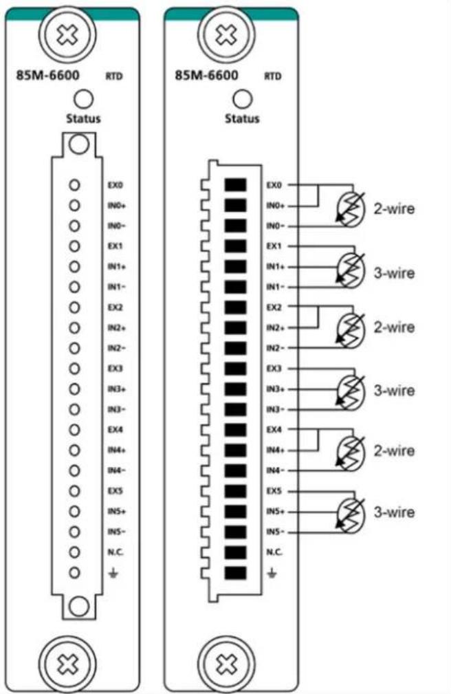
85M-6810-T: Thermocouple
The 85M-6810-T module provides 8-channel TC which features high density I/O with a flexible topology and hot-swappable functionality. This module is cost-effective solution for most industrial application.
Block Diagram
The following is the 85M-6810-T module's block diagram. The 85M-6810-T uses an MCU processor that has three communication interfaces: SPI, RS232, and USB. Whereas the 85M-6810-T module communicates with the modular head through RS-232 and USB interfaces. The 85M-6810-T has isolation protection up to 3K VDC or 2K Vrms.
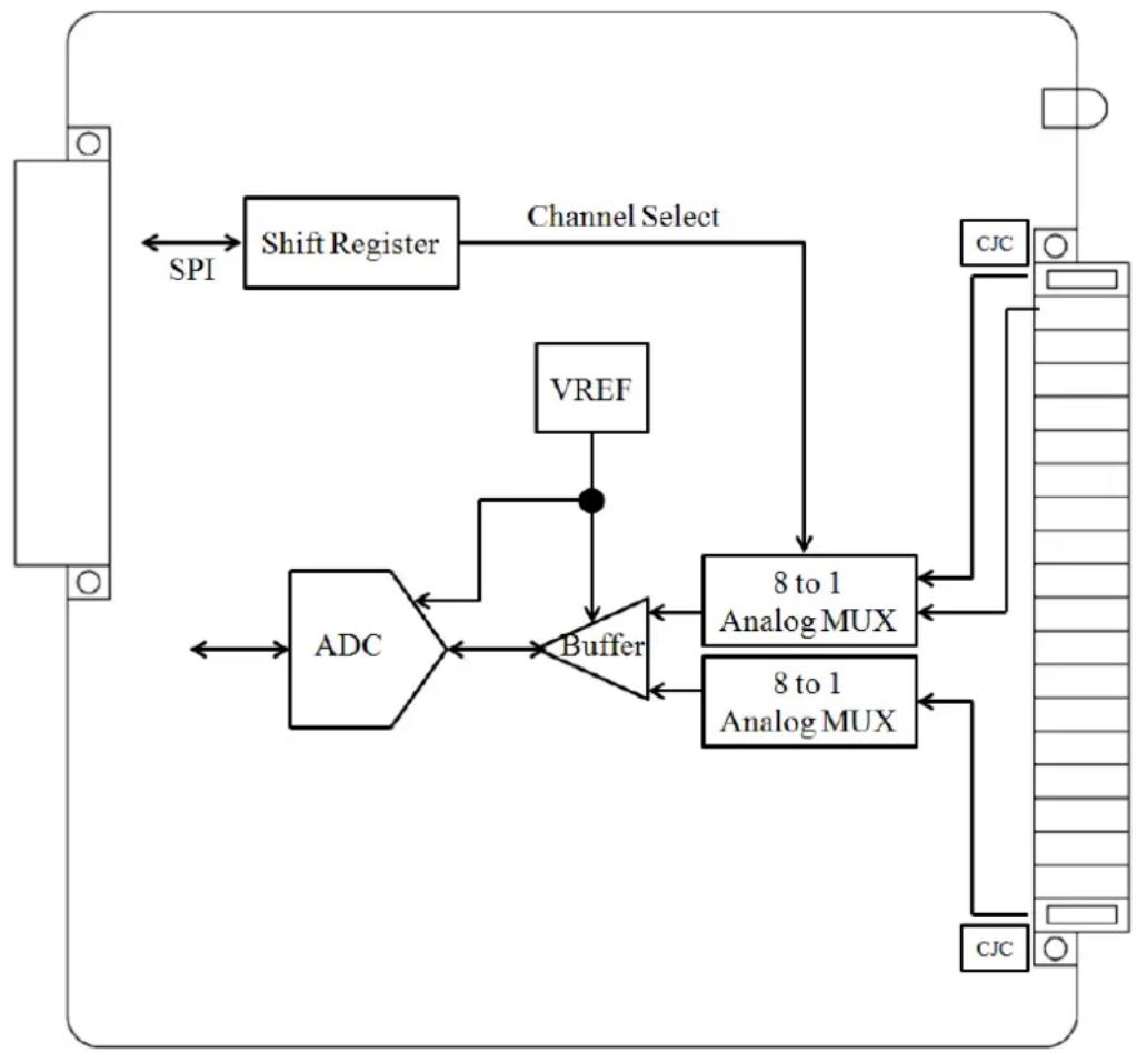
flowchart
graph TD
    A["ADC"] --> B["Buffer"]
    C["Shift Register"] --> D["Channel Select"]
    D --> E["VREF"]
    E --> F["8 to 1 Analog MUX"]
    F --> G["8 to 1 Analog MUX"]
    G --> H["CJC"]
    H --> I["CJC"]
    I --> J["Switch Register"]
    J --> K["SPI"]
    style A fill:#f9f,stroke:#333
    style C fill:#f9f,stroke:#333
    style D fill:#ccf,stroke:#333
    style E fill:#cfc,stroke:#333
    style F fill:#fcc,stroke:#333
    style G fill:#fcc,stroke:#333
    style H fill:#fcc,stroke:#333
    style I fill:#fcc,stroke:#333
    style J fill:#cff,stroke:#333
Specifications
Inputs and Outputs
Analog Inputs: 8 channels
Isolation: 3K VDC or 2K Vrms
Thermocouple Inputs
Sensor Type: J (0 to 750°C), K (-200 to 1250°C), T (-200 to 350°C), E (-200 to 900°C), R (-50 to 1600°C), S (-50 to 1760°C), B (600 to 1700°C), N (-200 to 1300°C)
Millivolt Type:
• Mode: ±78.126 mV, ±39.062 mV, ±19.532 mV
- Fault and over-voltage protection: -35 to +35 VDC (power off); -25 to +30 VDC (power on)
Sampling Rate (single channel): • All channels: 12 samples/sec • Per channel: 1.5 samples/sec
Resolution: 16 bits
Accuracy: ±0.1% FSR @ 25°C ±0.3% FSR @ -40 and 75°C
Input Impedance: 1 Mohms (min.)
Physical Characteristics
Wiring: I/O cable, max. 16 AWG
Connector: Spring type terminal block
Environmental Limits
Operating Temperature: -40 to 75°C
Pin Assignment and Wiring Guide
The following is the 85M-6810-T module's pin assignment and wiring guide.
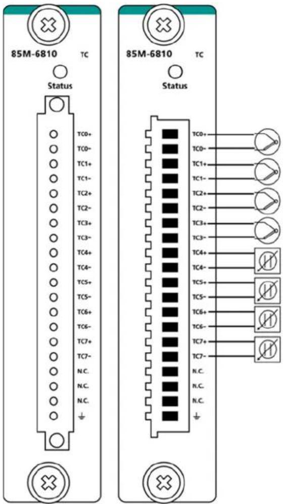
NOTE
Grounding the device through the earth/ground pin ( ↓ ) gives 6kV ESD protection.
85M-5401-T: Serial Ports
The 85M-5401-T module is a 3-in-1 DB-44 serial communication port module, which supports RS-232, RS-422, and RS485 communications. The following table shows the serial and protocol communication parameters supported by the 85M-5401-T.
| Parameter Supported Values | |
| Baudrate | 300, 600, 1200, 2400, 4800, 9600, 19200, 38400, 57600, 115200, 921600 bps(Default: 9600 bps) |
| Mode | RS-232/422/485 (Default: RS-232) |
| Duplex | Full or Half duplex (Default: Full duplex) |
| Parity | Odd, None or Even (Default: None) |
| Data Bits 7 or 8 Bits (Default: 8 Bits) | |
| Stop Bits 1 Bit | |
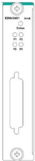
View of the 85M-5401 front panel.

ATTENTION
The ioPAC RTU controller only supports up to 2 85M-5401-T modules.
Block Diagram
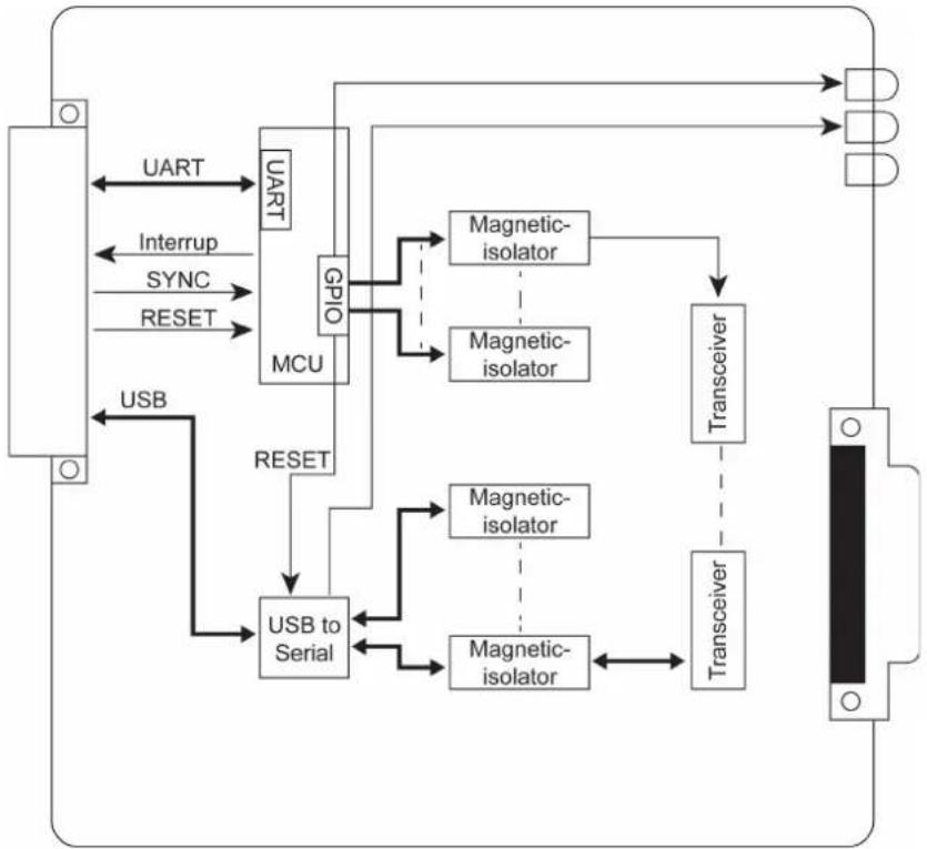
Below is the 85M-5401-T module's block diagram. This module communicates with the modular head by USB and UART. The MCU processor accesses I/O information through the GPIO pin. The 85M-5401-T has isolation protection up to 3K VDC or 2K Vrms, and magnetic isolators between the I/O and the MCU processor.
flowchart
graph TD
    A["UART"] --> B["GPIO"]
    B --> C["Magnetic-isolator"]
    B --> D["Magnetic-isolator"]
    C --> E["Transceiver"]
    D --> E
    F["USB"] --> G["USB to Serial"]
    G --> H["Magnetic-isolator"]
    G --> I["Magnetic-isolator"]
    H --> J["Transceiver"]
    I --> J
    K["Interrupt"] --> B
    L["SYNC"] --> B
    M["RESET"] --> B
    N["UART"] <--> O["GPIO"]
    O <--> P["Magnetic-isolator"]
    O <--> Q["Magnetic-isolator"]
    R["USB"] <--> S["USB to Serial"]
    S <--> T["Magnetic-isolator"]
    U["TRANSCEIVER"] --> J
Specifications
The following are the 85M-5401-T module's product specifications.
Serial Communication
Interface: 4 RS-232/422/485 ports, software selectable (DB44 male)
Isolation: 3K VDC or 2K Vrms
Note: DB44 to 4-port DB9 cable included in the package.
Serial Communication Parameters
Parity: None, Even, Odd
Data Bits: 7, 8
Stop Bits: 1, 2
Flow Control: RTS/CTS, XON/XOFF
Baudrate: 300 bps to 921.6 Kbps
Serial Signals
RS-232: TxD, RxD, RTS, CTS, DTR, DSR, DCD, GND
RS-422: Tx+, Tx-, Rx+, Rx-, GND
RS-485-4w: Tx+, Tx-, Rx+, Rx-, GND
RS-485-2w: Data+, Data-, GND
Physical Characteristics
Connector: DB44 female
Environmental Limits
Operating Temperature: -40 to 75°C
Power Requirements
Power Consumption: 1.24 W @ 3.3 VDC
MTBF (mean time between failure)
Time: 596,611 hrs
Database: Telcordia (Bellcore)
Pin Assignment and Wiring Guide
The 85M-5401-T module's pin assignment and wiring guide follows. The DB44 to 4-port DB9 cable should be included in the package.
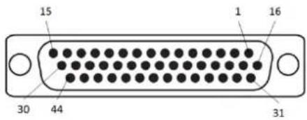
DB44 Pin Assignments
DB44 (Female): RS-232
| Pin | Signal | Pin | Signal | Pin | Signal |
| 1 | TxD3 | 16 | CTS3 | 31 | DCD3 |
| 2 | RxD3 | 17 | DTR3 | 32 | - |
| 3 | RTS3 | 18 | DSR3 | 33 | GND |
| 4 - 19 - 34 - | |||||
| 5 | TxD2 | 20 | CTS2 | 35 | DCD2 |
| 6 | RxD2 | 21 | DTR2 | 36 | - |
| 7 | RTS2 | 22 | DSR2 | 37 | GND |
| 8 - 23 - 38 - | |||||
| 9 | TxD1 | 24 | CTS1 | 39 | DCD1 |
| 10 | RxD1 | 25 | DTR1 | 40 | - |
| 11 | RTS1 | 26 | DSR1 | 41 | GND |
| 12 | - | 27 | - | 42 | DCD0 |
| 13 | TxD0 | 28 | CTS0 | 43 | - |
| 14 | RxD0 | 29 | DTR0 | 44 | GND |
| 15 | RTS0 | 30 | DSR0 | ||
DB44 (Female): RS-422/RS-485 (4-wire)
| Pin | Signal | Pin | Signal | Pin | Signal |
| 1 | RxD3+(B) | 16 | - | 31 | TxD3-(A) |
| 2 | TxD3+(B) | 17 | RxD3-(A) | 32 | - |
| 3 - 18 - 33 GND | |||||
| 4 - 19 - 34 - | |||||
| 5 | RxD2+(B) | 20 | - | 35 | TxD2-(A) |
| 6 | TxD2+(B) | 21 | RxD2-(A) | 36 | - |
| 7 - 22 - 37 GND | |||||
| 8 | - | 23 | - | 38 | - |
| 9 | RxD1+(B) | 24 | - | 39 | TxD1-(A) |
| 10 | TxD1+(B) | 25 | RxD1-(A) | 40 | - |
| 11 | - | 26 | - | 41 | GND |
| 12 | - | 27 | - | 42 | TxD0-(A) |
| 13 | RxD0+(B) | 28 | - | 43 | - |
| 14 | TxD0+(B) | 29 | RxD0-(A) | 44 | GND |
| 15 - 30 - | |||||
DB44 (Female): RS-485 (2-wire)
| Pin | Signal | Pin | Signal | Pin | Signal |
| 1 Data3+(B) 16 - 31 - | |||||
| 2 | - | 17 | Data3-(A) | 32 | - |
| 3 - 18 - 33 GND | |||||
| 4 - 19 - 34 - | |||||
| 5 Data2+(B) 20 - 35 - | |||||
| 6 | - | 21 | Data2-(A) | 36 | - |
| 7 - 22 - 37 GND | |||||
| 8 - 23 - 38 - | |||||
| 9 Data1+(B) 24 - 39 - | |||||
| 10 | - | 25 | Data1-(A) | 40 | - |
| 11 | - | 26 | - | 41 | GND |
| 12 - 27 - | 42 - | ||||
| 13 | Data0+(B) | 28 | - | 43 | - |
| 14 | - | 29 | Data0-(A) | 44 | GND |
| 15 - 30 - |
DB9 Pin Assignment
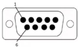
DB9 (Female): RS-232/RS-422/RS-485
| Pin | RS-232 | RS-422/RS-485(4-wire) | RS-485 (2-wire) |
| 1 DCD TxD-(A) | - | ||
| 2 | RxD | TxD+(B) | - |
| 3 | TxD | RxD+(A) | Data+(B) |
| 4 | DTR | RxD-(B) | Data-(A) |
| 5 | GND | GND | GND |
| 6 DSR | - | - | |
| 7 RTS | - | - | |
| 8 CTS | - | - | |
| 9 - | - | - |
DIP Switch
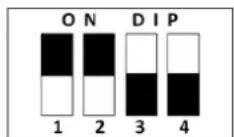
| DIP Switch | ON | OFF |
| 1 | 1K Ohm Pull High Resistor | 150K Ohm Pull High Resistor (default) |
| 2 | 1K Ohm Pull Low Resistor | 150K Ohm Pull High Resistor (default) |
| 3 | 120 Ohm Terminal Resistor | None (default) |
| 4 | Reserved | Reserved (default) |
- ioPAC 8500 Hardware User's Manual
- Copyright Notice
- Trademarks
- Disclaimer
- Technical Support Contact Information
- Moxa Americas
- Moxa Europe
- Moxa India
- Moxa China (Shanghai office)
- Moxa Asia-Pacific
- ioPAC 8500 Hardware Introduction.... 3-1
- 85M Module Hardware Introduction.... 4-1
- Overview
- Package Checklist
- ioPAC 8500
- 85M Modules
- Optional Accessories (can be purchased separately)
- □ Basic Installation
- □ Configuring Power
- □ Installing a microSD Card
- □ Connecting to the Network
- Serial Connectivity
- □ Battery
- Basic Installation
- DIN Rail Installation Procedure
- Installing the ioPAC 8500 on a DIN Rail
- NOTE A wall mount kit can be purchased separately.
- Removing the ioPAC 8500 from a DIN Rail
- Module Installation Procedure (Power-Off)
- Module Installation Procedure (Power-On)
- WARNING
- Configuring Power
- Powering on the ioPAC Controller
- ATTENTION
- Grounding the ioPAC
- NOTE
- Installing a microSD Card
- Connecting to the Network
- Ethernet Communication
- RJ45 Ethernet Connector
- RJ45 Connector Pin Assignment
- M12 Ethernet Connector
- M12 Ethernet Connector Pin Assignments
- Port Trunking
- Connecting to a Serial Device
- Serial Console (Debug Port)
- Battery
- Caution
- □ Appearance and Dimensions
- Hardware Block Diagrams
- □ Product Hardware Specifications
- ☐ ioPAC 8500 LED Indicators
- □ The Toggle Switch
- ☐ Toggle Switch: Factory Reset Process
- Appearance and Dimensions
- Appearance
- ioPAC 8500 Modular Head
- Dimensions (unit: mm(inch))
- Product Hardware Specifications
- Specifications
- Computer
- Memory:
- Ethernet Interface
- Serial Communication
- Interface:
- Serial Communication Parameters
- Serial Signals
- Software Characteristics
- Power Requirements
- Physical Characteristics
- Dimensions:
- Weight:
- Environmental Limits
- Standards and Certifications
- Warranty
- ioPAC 8500 LED Indicators
- System LEDs
- PWR (Power LED)
- RDY (Ready LED)
- IO (Expansion Module LED)
- C/C++ Version LEDs: LED1 and LED2
- IEC-61131-3 Compliant LEDs: R/S and ERR
- Communication LEDs
- P1 and P2
- LAN1 and LAN2
- The Toggle Switch
- In IEC-61131-3 Models
- In C/C++ Models
- Toggle Switch: Factory Reset Process
- 85M Module Descriptions
- Common Specifications
- Module Specifications
- 85M-1602-T: Digital Input, 24 VDC, Sink/Source, Dry Contact
- Block Diagram
- Dry Contact:
- Wet Contact (DI to GND):
- Counter Frequency: 5 kHz
- MTBF (mean time between failure)
- Pin Assignment and Wiring Guide
- 85M-2600-T: Digital Output, 24 VDC, Sink Type
- Inputs and Outputs
- Digital Outputs
- 85M-38XX-T: Analog Input
- 85M-3800-T: 8 analog inputs, 4 to 20 mA Specifications
- 85M-3801-T: 8 analog inputs, 4 to 20 mA, 40 kHz Specifications
- Analog Inputs
- Accuracy:
- Sampling Rate:
- 85M-3810-T: 8 analog inputs, 0 to 10 VDC Specifications
- 85M-3811-T: 8 analog inputs, 0 to 10 VDC, 40 kHz Specifications
- Analog Input Data Format
- 85M-6600-T: RTD
- RTD Inputs
- Input Type:
- Sampling Rate (single channel):
- 85M-6810-T: Thermocouple
- Thermocouple Inputs
- Millivolt Type:
- 85M-5401-T: Serial Ports
- DB44 Pin Assignments
- DB9 Pin Assignment
- DIP Switch
Brand : Moxa
Model : RM-3810-T
Category : Uncategorized