3500 - Measuring instrument PCE Instruments - Free user manual and instructions
Find the device manual for free 3500 PCE Instruments in PDF.


| Product Type | Hardness Tester (Portable) |
| Brand | PCE Instruments |
| Model | PCE-3500 |
| Measurement Methods | UCI (Ultrasonic Contact Impedance) and Rebound (Leeb) |
| Hardness Scales | Rockwell C, Brinell, Vickers, Leeb, Tensile Strength (via Brinell), and custom user scales |
| Calibration Scales | 88 scales across 8 types and 11 materials |
| Information Processing Unit Dimensions | 160 x 75 x 30 mm |
| UCI Probe Dimensions | ∅25 x 140 mm |
| Rebound Probe Dimensions | ∅20 x 150 mm |
| Weight (Processing Unit) | 0.25 kg |
| Weight (UCI Probe) | 0.125 kg |
| Weight (Rebound Probe) | 0.25 kg |
| Power Supply | Three 1.5V AA rechargeable batteries (NiCd or NiMH) |
| Battery Life | Approx. 6 hours (NiCd) or 10 hours (NiMH) |
| Operating Temperature | -20°C to +40°C |
| Display | LCD with adjustable brightness |
| Memory | Up to 60,000 measurements |
| Data Output | USB cable for PC transfer |
| Language Options | English, Russian |
| Package Contents | Processing unit, UCI probe (10N or 50N), rebound probe, charger, batteries, USB cable, manual, hardness test blocks |
| Maintenance | Clean probe tip with soft cloth and alcohol; avoid water and solvents; store in carry case with batteries removed if idle >14 days |
| Safety Warnings | Use only rechargeable batteries; avoid sharp impacts on diamond indenter; keep away from aggressive chemicals and direct sunlight; do not immerse in liquids |
| Spare Parts / Repairability | Contact manufacturer or authorized service center; warranty covers defects within one year (excludes battery, charger, bag) |
Frequently Asked Questions - 3500 PCE Instruments
User questions about 3500 PCE Instruments
0 question about this device. Answer the ones you know or ask your own.
Ask a new question about this device
Download the instructions for your Measuring instrument in PDF format for free! Find your manual 3500 - PCE Instruments and take your electronic device back in hand. On this page are published all the documents necessary for the use of your device. 3500 by PCE Instruments.
USER MANUAL 3500 PCE Instruments
Southpoint Business Park
Ensign way
Hampshire / Southampton
United Kingdom, SO31 4RF
From outside UK: +44
Tel: (0) 2380 98703 0
Fax: (0) 2380 98703 9
info@pce-instruments.com
www.pce-instruments.com/english
www.pce-instruments.com
Bedienungsanleitung
Durometer
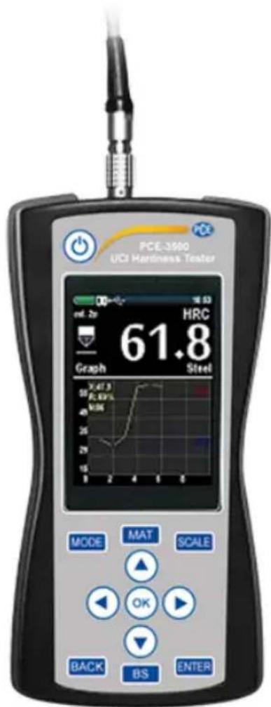
PCE-3500
natural_image
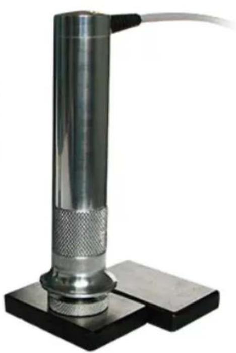
Close-up of a metallic cylindrical device with textured surface and attached probe, mounted on a black base (no visible text or symbols)CONTENTS
- Introduction 2
- Appointment 2
- Specifications 2
- Packing list 5
- Principle of operation 5
- Preparations for operation 7
- Basics of operation 8
- Operation 9
- Hardness measurement 19
- Measurement modes 30
- Calibration 35
- Technical maintenance, special conditions of operation 46
- Precautions and trouble shouting 48
- Manufacturer's guarantee and service maintenance 49
1. Introduction
The following operation manual explains the preparation, setup, principles of operation, usage, and troubleshooting of the hardness tester PCE-3500.
Please, read this instructions carefully for operate the hardness tester PCE-3500 functions quickly and effectively.
In doing this you will be able to take full advantage of the function range of the instrument. At the same time, you will also avoid errors and wrong operation which in turn would cause incorrect test results and thus could lead to injury and damage.
2. Appointment
The hardness tester PCE-3500 is handy, easy to operate and can carry out tests quickly without any difficulties.
Hardness tester PCE-3500 is mainly suitable:
• for measurement hardness of low and non-alloyed steels;
• for measurement hardness of high-alloyed steels;
• for measurement hardness of nonferrous metals.
3. Specifications
3.1. Calibration scales
Device has 88 calibration scales of hardness that conventionally divided into eight scales and eleven materials for each:
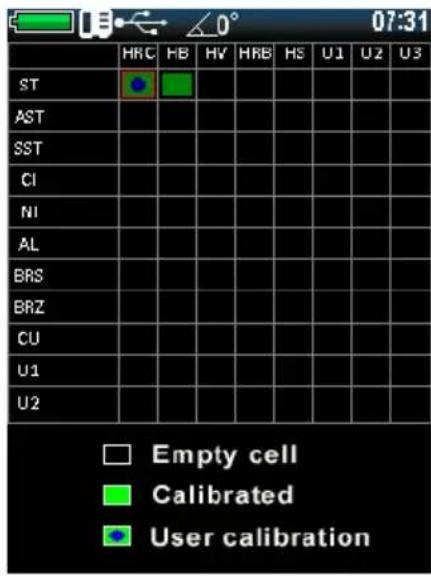
Each of the scales can be additionally calibrated by 1 or 2 points. Also, the unit measures in Leeb scale (with rebound probe) and Tensile strength, through the automatic recalculation of the Brinell scale.
3.2. The limits of permissible basic error of measurement
| Hardness scale | Error |
| Rockwell C | ±2 |
| Brinell | ±10 |
| Vickers | ±15 |
| Leeb | ±15 |
| Tensile strength | Not rated |
3.3. Working conditions: from -20°C to +40°C
3.4. Overall dimensions
| Name | Overall dimensions, mm |
| Information processing unit | 160x75x30 |
| UCI probe | ∅25x140 |
| Rebound probe | ∅20x150 |
3.5. Weight of the instrument and probes
| Name | Weight, kg |
| Information processing unit | 0,25 |
| UCI probe | 0,125 |
| Rebound probe | 0,25 |
3.6. Power supply
Battery operation: three 1,5V AA rechargeable batteries.
NiCd (approx. 6 hours operation) or NiMH (approx. 10 hours operation).
NOTE: Do not allow using of non-rechargeable cells!
3.7. To save battery charge in the menu there are settings of device auto switch off and brightness of the display.
3.8. Requirements of the test material
| Surface roughness, not more, Ra | |
| UCI (10N) probe U1 | 1,5 |
| UCI (50N) probe U1 | 2,5 |
| Rebound probe D1 | 3,2 |
| Radius of curvature of the surface, mm | |
| UCI probe U1 | 5 |
| Rebound probe D1 | 10 |
| Weight of the test material, not less, kg | |
| UCI probe U1 | 0,1 |
| Rebound probe D1 | 5 |
| Thickness of the test material, not less, mm | |
| UCI probe U1 | 1 |
| Rebound probe D1 | 10 |
4. Packing list
4.1. Information processing unit 1 pc
4.2. Probes:
UCI (10N) ____ pc
UCI (50N) _ pc
Rebound (Leeb) ____ pc
4.3. Charger 1 pc
4.4. Battery 3 pc
4.5. USB cable 1 pc
4.6. Operation manual 1 pc
4.7. Hardness test block __pc
5. Principle of operation
5.1. Rebound method
Rebound probe consists of an impact body and the capture. The impact body has a carbide tip and a permanent magnet for generating a voltage pulse; the impact device has a spring mechanism for loading and impelling the impact body, and an induction coil for detecting the magnet in the impact body. In the rebound hardness testing method, the speed variation caused by the impact of the impact body against the material surface is measured.
The impact energy is adjusted via the spring for the measurement. The impact body contained in the tube of the impact device is impelled against the test surface by means of the release button. In the course of this, the magnet of the impact body induces in the coil a voltage signal whose height is proportional to the impact phase speed. The impact causes a plastic deformation of the material and a permanent spherical indentation is produced in the surface. This
plastic deformation leads to a loss of energy of the impact body and thus to a lower speed after the actual rebound phase.
The speed ratio is determined exactly at the moment of impact/rebound by means of the special signal processing. The speed ratio is therefore unaffected by the impact direction. As opposed to this, other rebound hardness testers require presetting of the impact direction in fixed steps (influence of gravitation on the speed ratio) - which constitutes a considerable disadvantage with frequently changing test positions.
5.2. UCI method
The Vickers diamond is fixed to the tip of a round metal rod. This metal rod is excited, to its resonant frequency of approx. 78 kHz, into longitudinal oscillations. When the Vickers diamond contacts the sample surface, the resonant frequency will change. This change happens in relation to the size of the indent area from the Vickers diamond. The size, in turn, is a measure for the hardness of the tested material. Resonant frequencies can be measured very accurately. This is why the UCI method is suited to make the evaluation of Vickers indents, and thus of the complete test procedure, so much easier and quicker.
There are also two additional advantages:
- the measurement is made under load. (No impairment of the measurement due to elastic resilience);
- the hardness measurement is based on the area of the indent and not on the length of the indent diagonals.
The measurement is thus less affected by surface roughness; even gunmetal-finished surfaces can be measured.
Concerning the UCI method, the measurement value is also dependent on the Young's modulus of the material.
6. Preparations for operation
6.1. Battery supply
The hardness tester PCE-3500 is powered by accumulators. You will need three AA 1,5V rechargeable (Nickel-Cadmium or Nickel-Metalhydrid) batteries.
NOTE! The batteries must be fully charged before first use.
Use of the batteries.
- Open the battery compartment.
- Insert the batteries, observing the correct polarity.
- Close the battery compartment.
Used or defective batteries are special refuse and must be disposed of according to the governing laws!
6.2. Connection of probes.
Socket of the probe is at the top of the information processing unit. Connect the probe cable to the PCE-3500 socket in accordance with the marks on the connector.
7. Basics of operation
7.1. Keys
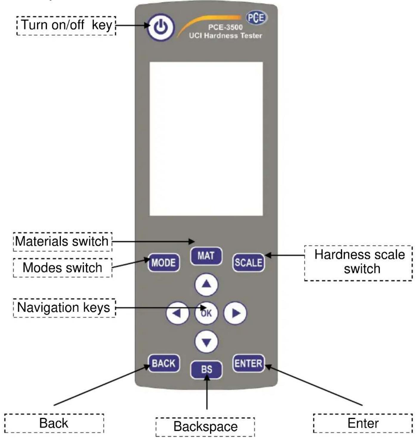
7.2. Choice of the measurement method.
7.2.1. Rebound method of measuring hardness is appropriate for:
- testing objects weighing more than 5 kg and a wall thickness more than 10 mm;
- massive products, products with a coarse-grained structure, forged and cast products;
- testing objects with minimal preparation of the surface.
7.2.2. UCI method of measuring hardness is appropriate for:
- testing objects with low mass and small wall thickness;
- testing objects with a glossy surface (with special requirements to the minimum size of the imprint);
- surfaces of the testing objects with hardened layers.
8. Operation
8.1. Preparation of the test material.
The surface must be clean and free of oil, grease and dust.
The surface roughness of the material should meet the requirements of a specific probe (paragraph 3.8).
8.2. Features of the methods of measurement of metal hardness:
8.2.1. UCI method:
Distinct reading variations may especially occur with a mass lower than 0.1 kg and a specimen thickness of less than 1 mm if the test material is excited to resonance or sympathetic oscillations.
Otherwise, such test materials must be fixed to a solid base, e.g. using a viscous paste. The same applies to the hardness test blocks.
8.2.2. Rebound method:
With smaller and less heavy test objects, the impact effect of the impact device may cause vibrations which could produce distorted measurement results.
- Test objects weighing less than 2 kg must in any case be fixed to the support using couplant so that there are no any vibrations.
- Test objects weighing between 2 kg and 5 kg must be placed on a large metal support (e.g. a table) in such a way that they are not moved or caused to vibrate by the impact.
8.3. Device menu
After connecting the probe, hold TURN ON/OFF button until logo appears on the display:

Then, you get to the main menu of the device:
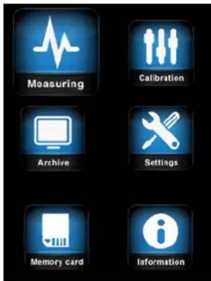
The menu consists of 6 sections:
- Measuring
- Calibration
- Archive
- Settings
- Memory card
- Information
Move through the menu using the navigation keys, for entering
press key . OK
8.3.1. Measuring
Selecting Measuring, you go to the measurement of hardness mode, depending on the probe it will display the angle of the probe at the top of the screen (for rebound probe), or the state of the diamond indenter (for UCI probe).
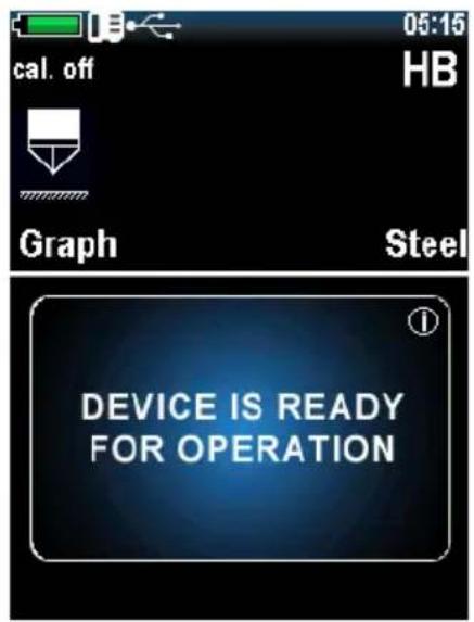
Detailed description of the measurement of hardness, see paragraph 9.
8.3.2. Calibration
Selecting Calibration, you go to the table of calibrations where the scale conventionally divided into eight hardness scales: Rockwell (HRC), Brinell (HB), Vickers (HV), Rockwell (HRB), Shore (HS), User 1 (U1), User 2 (U2), User 3 (U3).
Each of the scales can be calibrated to 11 conventional materials: Steel (ST), Alloy Steel (AST), Stainless steel (SST), Cast Iron (CI), Nodular Iron (NI), Aluminums (Al), Brass (BRS), Bronze (BRZ), Copper (CU), User material 1 (U1), User material 2 (U2).
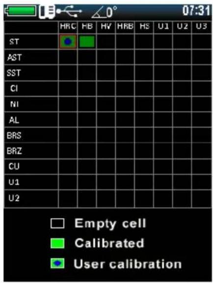
Detailed description of the calibration process, see paragraph 11.
8.3.3. Archive
Selecting Archive you go to the list of saved measurements, which displays Measurement name, Date and time of the measurement, Scale, Material and Average Value.
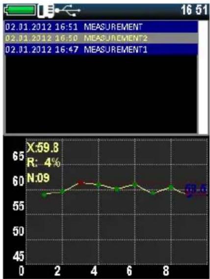
line
| Measurement | Value | | ----------- | ----- | | X:59.8 | 59.8 | | R: 4% | 4% | | N:09 | 0.09 |You can store in memory up to 60 000 measurements.
Scroll through the list using the navigation keys and .

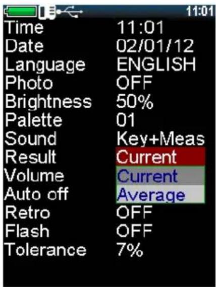
8.3.4. Settings
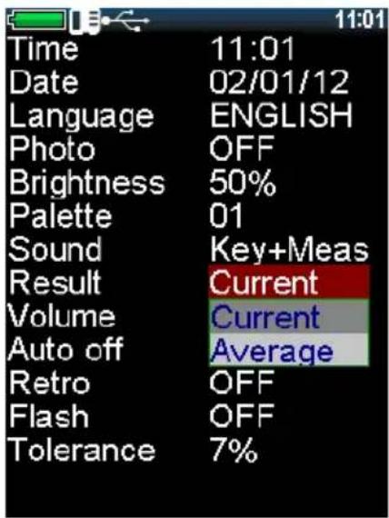
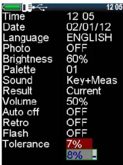
Selecting Settings you go to the settings menu for configure the following settings:
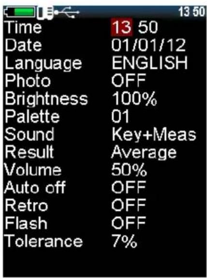
Time: time setting.
Date: date setting.
Language: selection language of the device menu (available English and Russian).
Photo: enable / disable the camera (for version with camera).
Brightness: setting the brightness of the display.
Palette: selection of menu themes (creation of color palette of menu makes with special software).
Sound: there are 4 modes of device sound (Off, Key, Measurement, Key and Measurement).
Result: displaying measurement results can be Current (display instantaneous values of measurements) and Average (unit accumulates the series of measurements and display average value of hardness).
Volume: setting the volume of the device.
Auto Off: setting of the automatic switch off device when it is not in use.
Retro: allows you to return to the measurement mode with saved last measurements after restarting of the device.
Flash: enable / disable the cameras flash (for version with camera).
Tolerance, %: This parameter is used only for Smart mode. Set the % value adjusts the range of deviations of measurements to be included in the calculation of the average for the series in Smart mode. Detailed description of the Smart mode, see paragraph 10.4.
Navigate and select options using the navigation keys.
8.3.5. Memory Card
Selecting Memory Card you go to the menu of memory.
8.3.5.1. Create backup copies of calibrations.
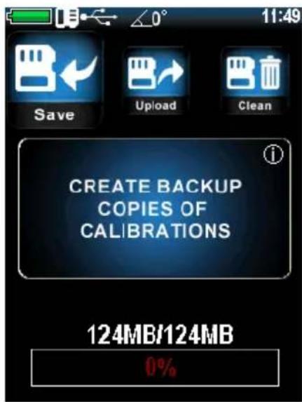
After calibration of the probe is recommended to create a backup copy of the calibration (usually the manufacturer makes the calibration of 1-2 scales, to check the probe). This is done in order to be able to resume adequate calibration after incorrect settings in the future.
8.3.5.2. Load backup copies of calibrations.
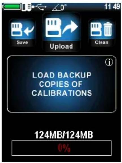
After the initial save of calibrations you can always download it to the probe. This function is needed for the resumption of adequate calibration in case of wrong settings of the probe.
8.3.5.3. Clear SD card
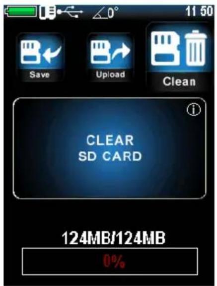
Clearing saved records in the archive and backup copies of calibrations: after clearing SD card the archive will be empty and backup copies of calibrations delete. To clean just stored archival records - transmit saved measurements to PC with special software. Thus backup calibrations will be unaffected.
At the bottom of the screen of this menu shown Memory state.
8.3.6. Information
In this menu you can view statistic information.

Scroll through the list using the navigation keys and .

9. Hardness measurement
9.1. Using of the UCI method
The design of UCI Probe is shown in Figure 1a. Probe has a special removable collapsible nozzle with the puck (Figure 1b). The puck provides the convenience of positioning the probe relative to the testing object and a clip for the measurements
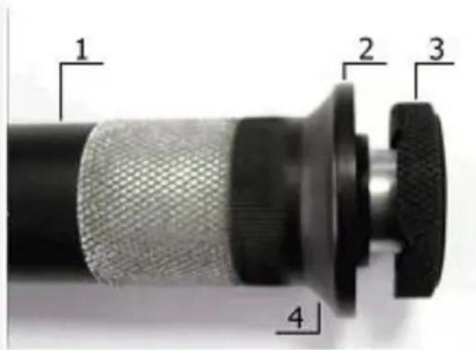
Figure 1a. UCI Probe U1 1 – Probe's body; 2 – Collapsible nozzle; 3 – Puck; 4 – Place for fingers
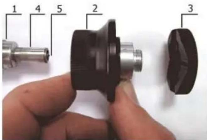
Figure 1b. Demounted nozzle 1 – Probe's body; 2 – Nozzle main part; 3 – Puck; 4 – Protective tube; 5 – Diamond.
One side of the puck is flat to using probe on flat surfaces. Another side has grooves for using a probe on cylindrical surfaces.
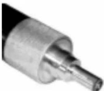
It is marked slots designed for ease of measurement of hardness on cylindrical products of various diameters. Probe with demounted nozzle is usually using to measure hardness in difficult places, such as narrow or deep groove.
The probe may be removed from the nozzle is used for measuring the hardness in the narrow and hard to reach places.
natural_image
Close-up of a metallic cylindrical connector with a pointed tip (no visible text or symbols)Figure 2
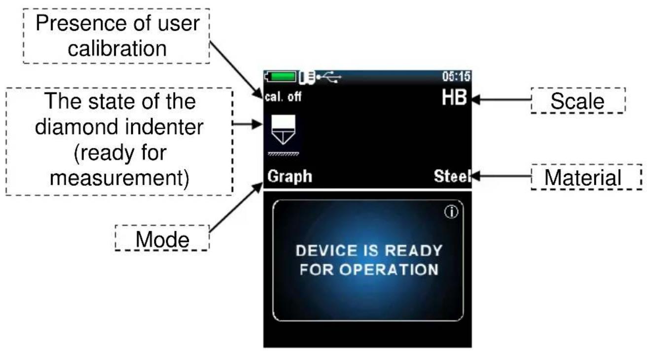
Turn on the hardness tester by pressing , and select the measurement mode. For select the measurement mode press

and chose the mode that will be used by keys and

then press . Detailed description of the modes, see graph 10.
flowchart
graph TD
    A["Presence of user calibration"] --> B(cal. off)
    C["The state of the diamond indenter (ready for measurement)"] --> B
    D["Mode"] --> E["Graph"]
    E --> F["05:15 HB"]
    F --> G["Scale"]
    F --> H["Steel"]
    I["DEVICE IS READY FOR OPERATION"] --> J["i"]
    J --> K["Material"]
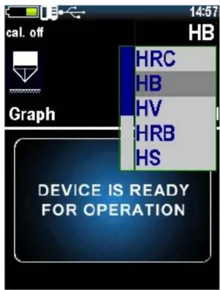
Then select the scale and material hardness for which there is a proper calibration (how to calibrate device see paragraph 11).
For select the hardness scale press and chose the scale that will be used by keys and then press.
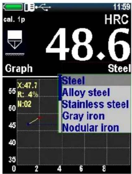
For select the material press and chose the material that will be used by keys and then press.
line
| Grade | Value | |-------|-------| | 1 | 47.7 | | 2 | 47.7 | | 3 | 47.7 | | 4 | 47.7 | | 5 | 47.7 | | 6 | 47.7 | | 7 | 47.7 | | 8 | 47.7 |During the measurement you can select other hardness scale. The displayed measurement reading will be converted according with the new hardness scale if it is calibrated.
NOTE! Calibration is carried out by the direct method, so the conversion is carried out on the basis of pre-calibration, and does not correspond to any standard.
Install the probe puck on the sample surface, keeping it in the tough skirt as shown in Figure 3a. By clicking on the skirt thrust both hands to bring the diamond tip of the probe perpendicular to the sample surface to the touch (Figure 3b). Slowly (in about 0.5 seconds) by pressing with a force of (5 or 1 kg depending on probe type) thrust skirt, push the diamond tip into the metal surface, preventing swinging (Figure 3c). After the sound signal, remove the probe from the tested object.
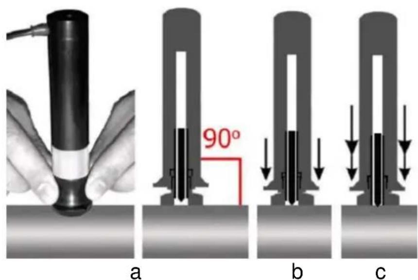
Figure 3
NOTE! For correct operation of the UCI probe try not to exceed the pressing force which is correspond to the probe (1 or 5 kg).
The display shows the value of hardness. The result of measurement is displayed on the display until the next measurement.
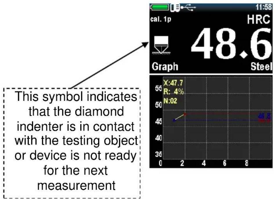
WARNING! Not allowed a sharp click and scratching sample by indenter, this may lead to exceeding the allowable value of error and damage the diamond indenter.
NOTE! The "exciter" in the probe is powered from the batteries. If the batteries are depleted you will get erratic test results.
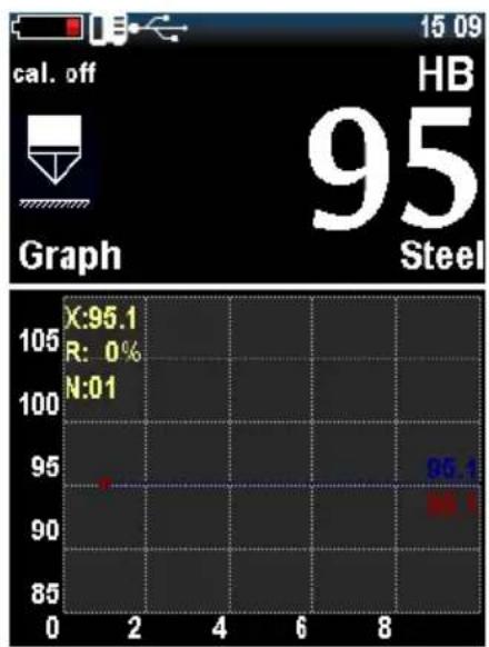
You can get the value of the current measurement or the average for the series of measurements, depending on the settings in Settings menu Current or Average:
After the measurement, you can save measurement (series of measurements) in the archive by pressing ENTER key .
line
| Time | Value | |------|-------| | 2 | 95.1 | | 8 | 95.1 |Keyboard appears:
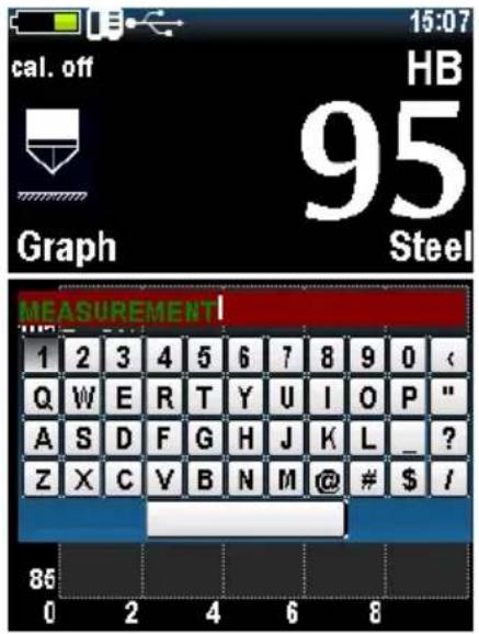
Move the cursor over the keyboard with navigation keys and select
symbols by pressing . Then press for saving. The record is stored in the archive.
9.2. Using of the Rebound (Leeb) method
Select scale and material with the existing calibration.


Press the buttons and to set the angle of the measurement. Fixed angle is displayed in the upper part of the display.
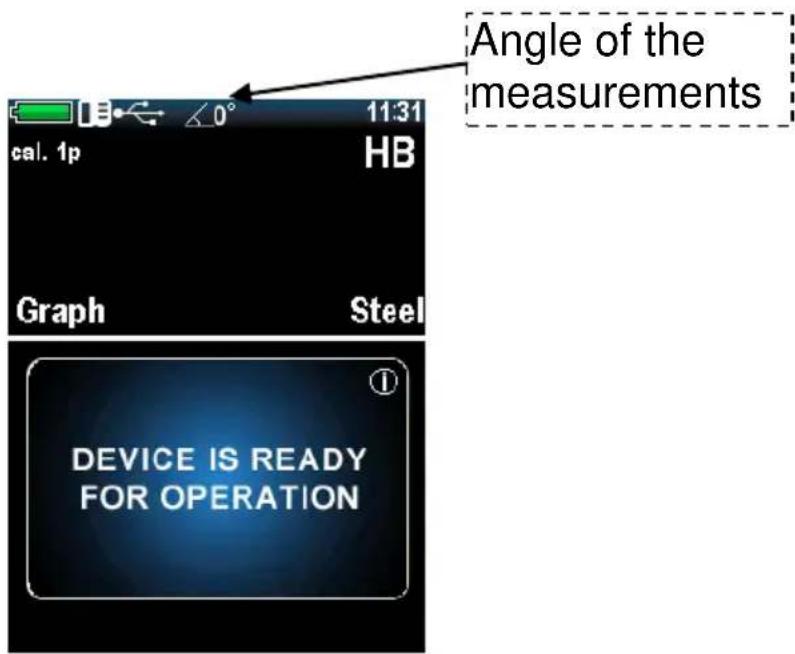
Position of the probe perpendicular to the ground plane corresponds to the angle 0^ .
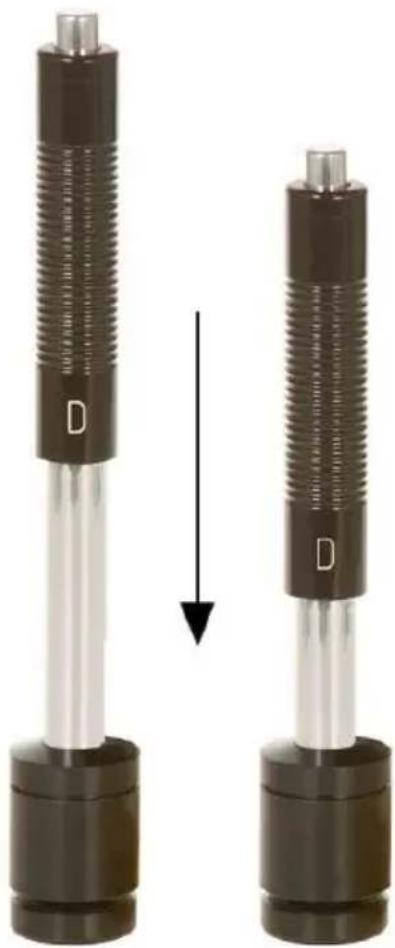
Place the rebound probe vertically onto the test surface and press it slightly against the surface. Charge the impact body by a charging mechanism pressing the probe enclosure until the clicks, as shown below:
natural_image
Two identical cylindrical mechanical components with black bases and threaded shafts, one showing a downward arrow (no text or symbols)Figure 4. Rebound probe
Press the release button on top of the impact device by finger of your free hand.
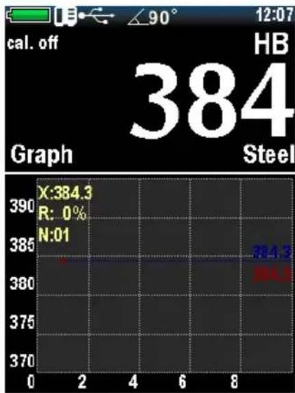
After pressing the shutter release button and the impact body hitting in the area of measurement sounds a beep and the display shows the value of measured hardness.
line
| X | Y | | ---- | ---- | | 384.3| 384.3|WARNING! The minimum distance between the imprints of measurements must be not less than 3 mm.
10. Measurement modes
To selecting the measurement mode go to the Measuring and press

The device will offer you the following measurement modes:
- Graph – mode of the construction graph;
- Histogram – mode of the construction columnar bar chart;
- Statistic – statistics mode;
- Smart – mode of filter incorrect measurements;
- Signal – the display signal mode (only for Leeb).
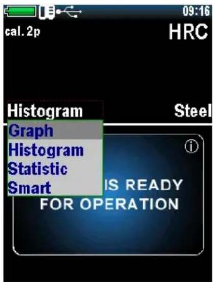
To select the measurement mode, press

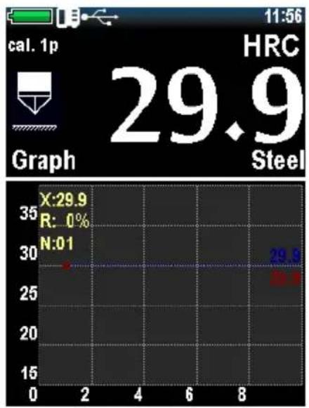
10.1. Graph mode
line
| X | R | N | | ---- | ---- | --- | | 29.9 | 0% | 01 | | 29.9 | | | | | | | | | | 29.9 |In graph mode, the device displays the current measurement value or average of series of measurements, depending on selected the Current or Average in Measurement settings menu:
10.2. Histogram mode
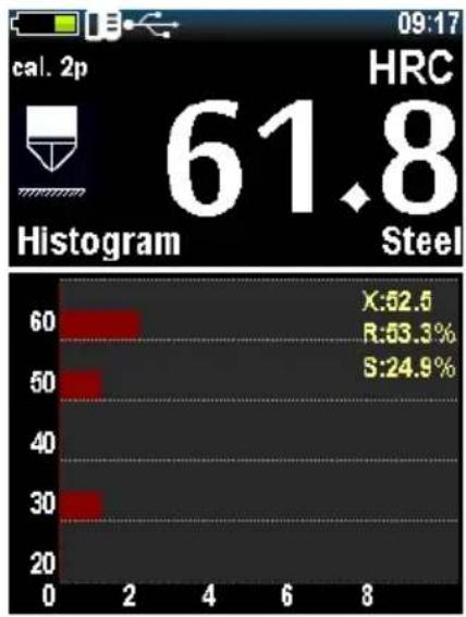
The device builds histogram of series measurements.
10.3. Statistics mode
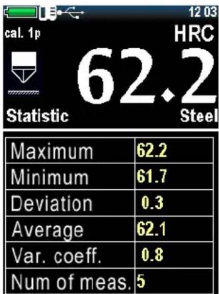
Statistics mode allows to monitoring the following parameters of measurement series: Maximum, Minimum, Deviation, Average, Number of measurements.
10.4. Smart mode
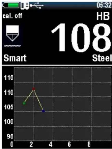
Smart mode allows the user to identify the general sequence of measurements. The device selects the first three series of measurements that do not exceed the specified tolerance. After that, the following measurements that exceed a given tolerance will be excluded from the series and will not be taken into account when calculating the average of the series.
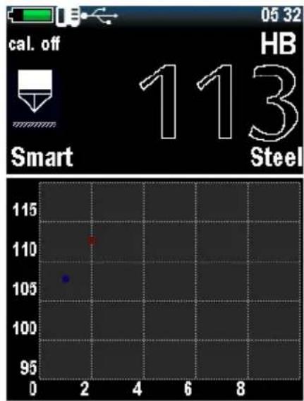
Filled with the color readings indicate that the device has fixed the general sequence and Smart mode is active.
line
| Time | Value | |------|-------| | 0 | 107 | | 2 | 112 | | 4 | 104 |To set the tolerance of Smart Mode, go to Settings:
And set the percentage tolerance values from 1 to 10.
10.5. Signal mode
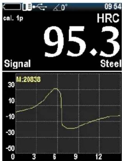
Mode is active only for Leeb probe and shows the voltage produced during the impact and rebound of impact body. M is the maximum value of the conditional code number which corresponds to the received signal.
line
| Time | Signal | |------|--------| | 0 | -10 | | 3 | 5 | | 6 | 28 | | 9 | -25 | | 12 | -10 |11. Calibration
11.1. Main calibration
To calibrate the probe you will need 3 samples of material with a known hardness. Hardness range should be wider than the hardness of the materials which will be measured (The values should be the maximum or more, minimum or less and average).
Select in the main menu Calibration:
The device goes to the table, each cell of the table corresponds to the certain scale of calibration for the certain material:
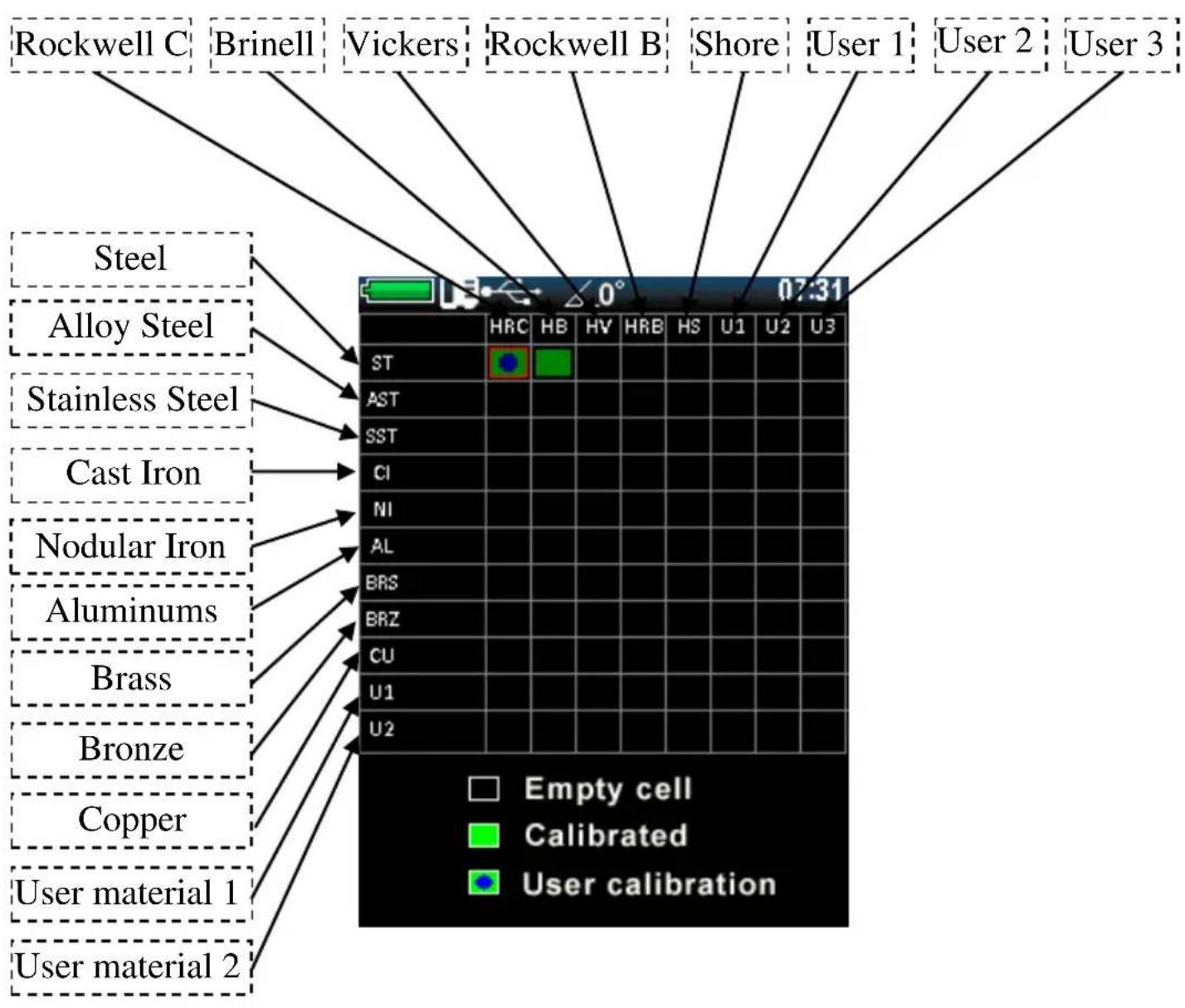
Each of the scales can be calibrated to 11 conventional materials: Steel (ST), Alloy Steel (AST), Stainless steel (SST), Cast Iron (CI), Nodular Iron (NI), Aluminum (Al), Brass (BRS), Bronze (BRZ), Copper (CU), User material 1 (U1), User material 2 (U2).
All calibrations of the device can be calibrated for any materials and any scales, and are divided in this way just for practicality.
Press the navigation keys to choice cell for calibration, for example HRC for Steel:
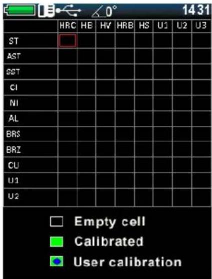
For select press , the table appears:
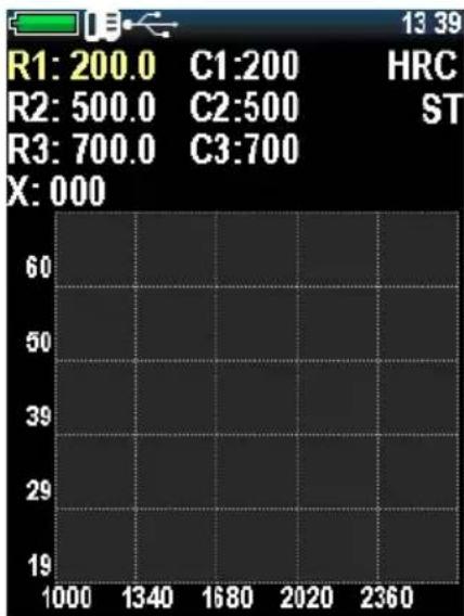
The device, making the measurement, gets the nominal codes, the purpose of calibration - is to find the correlation between the nominal code and hardness values (construction of the relation function).
To start the calibration, enter the real values of the samples by pressing . ENTER

for setting real values of Use the navigation keys hardness, to go to the next digit number, press

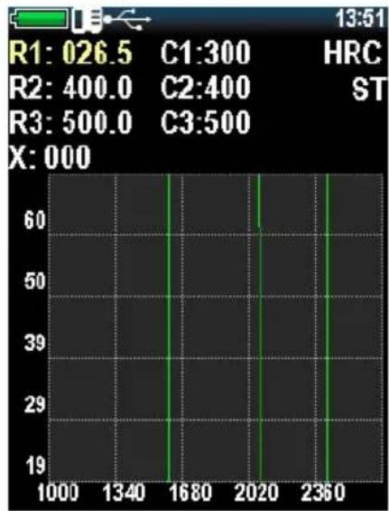
line
| Time | Value | |------|-------| | 1000 | 19 | | 1340 | 39 | | 1680 | 60 | | 2020 | 39 | | 2360 | 60 |For ending setting of first value press again , then the button

for adjusting the values of the next samples.
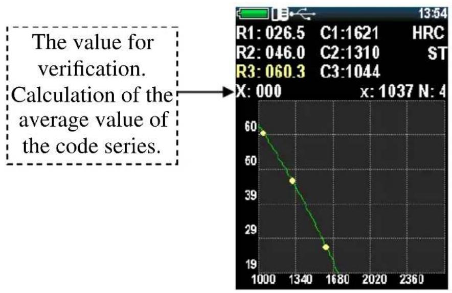
Then, move your selection on the hardness value according to the sample, and make at least 5 measurements. Make sure that the value of X (current value of the code) would not varied by more than 3% .
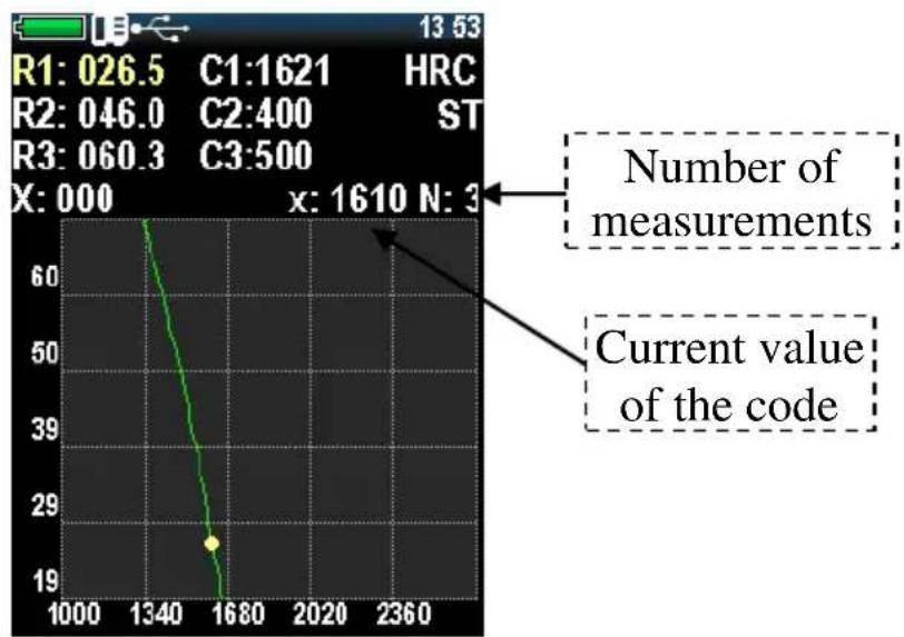
line
| Time | Value | |-------|-------| | 1000 | 60 | | 1340 | 50 | | 1680 | 29 | | 2020 | 19 | | 2360 | 19 |If you get an obvious error measurement, press and the last measurement will be removed from the series.
Go to the next nominal pressing, and make the same procedure with other samples, you end up with:
line
| x | y | | ---- | ---- | | 1000 | 60 | | 1340 | 39 | | 1680 | 29 | | 2360 | 19 |To check the correctness of the got values, move the cursor to the X:000 and take a few measurements on one of the sample.
For save, press , window will appear:
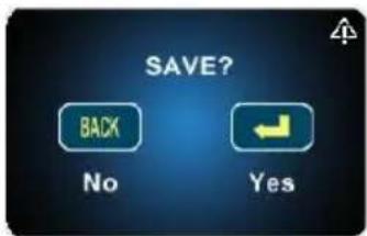
Press YES by . Calibration is saved. Select the appropriate material and scale, and device is ready for operation.
11.2. User (additional) calibration
Each of the saved main calibration may be further corrected. Additional calibration is recommended in the following cases:
- If the measurements of the device on the samples are constant, but differ from the nominal value of the standard block;
- After extended storage (more than 3 months.);
- After intensive operation;
- With a significant change in the operating conditions (temperature, humidity, etc.).
For the calibration of hardness scale needed one (single-point calibration) or two (two-point calibration) standard hardness tests samples with the maximum and minimum values for the controlled range of the hardness.
For example, we have two steel sample of known hardness of HRC, and device shows a stable deviation for hardness measurements on it. For making user two-point calibration select in main menu
Calibration:
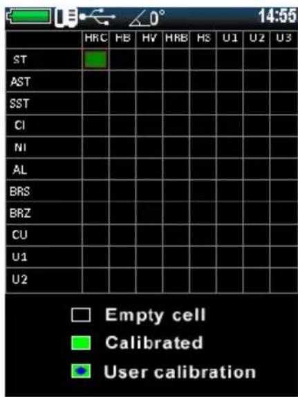
OK Press and the screen appears:
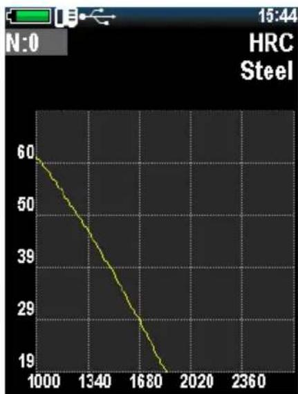
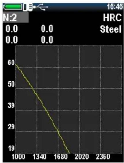
Press ENTER for select the number of calibration points, as we have
two sample - set 2 with pressing buttons and, then again ENTER
line
| X | Y | |-------|----| | 1000 | 60 | | 1340 | 50 | | 1680 | 39 | | 2020 | 29 | | 2360 | 19 |Move the cursor by pressing to select the first row. Take about 5 measurements on the first sample, the instrument will display the average of the series in accordance with the current calibration. If
you get an obvious error measurement, press and the last measurement will be removed from the series. You will get:
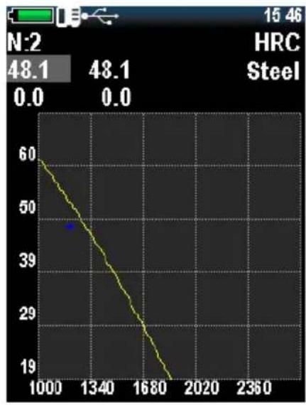
line
| X | Y | |-------|-----| | 1000 | 60 | | 1340 | 50 | | 1680 | 39 | | 2020 | 29 | | 2360 | 19 |Press and by pressing and set the nominal value
of the sample. To go to the next digit number, press , for saving first value press . After adjusting the value of the first sample you get:
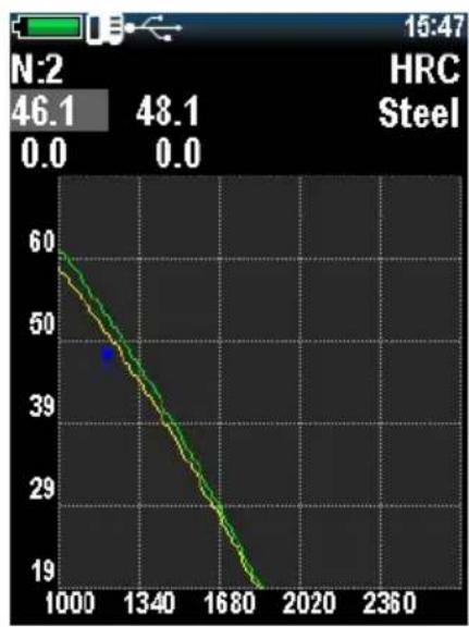
line
| Time | Value | |-------|-------| | 1000 | 60 | | 1340 | 50 | | 1680 | 39 | | 2020 | 29 | | 2360 | 19 |
Press to adjust the second sample value, and perform the same operation. In the end, get:
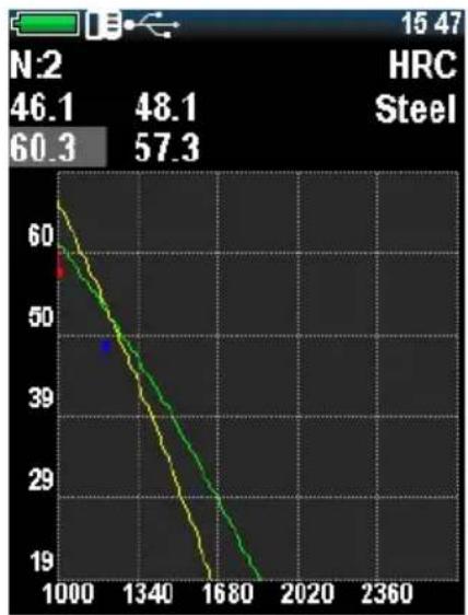
line
| X | Y | |-------|------| | 1000 | 60 | | 1340 | 50 | | 1680 | 29 | | 2020 | 19 | | 2360 | 19 |To save, press , window will appear:
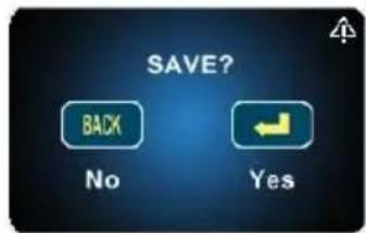
Press YES by . Calibration is saved. Select the appropriate material and scale, and device is ready for operation.
About the stored user calibration will symbolize the next state of the cell:
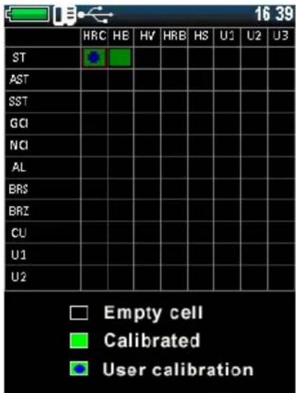
To delete user calibration, go to the user calibration mode and set to 0 for N:
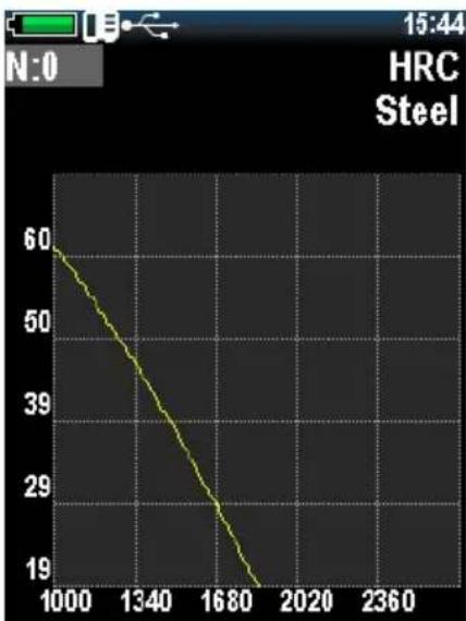
12. Technical maintenance, special conditions of operation
12.1 On the whole, hardness testers do not require any special maintenance. However, for the purpose of hardness tester stable operation, regular maintenance is advisable.
12.2. Probe maintenance
Clean hardmetal ball and diamond pyramid from dust, mud and oil traces. Use soft cloth impregnated with alcohol solution.
Check the probe operation regularly by conducting hardness measurements on hardness reference blocks. Do not use reference test block with expired period between verifications (more than 2 years).
12.3. Information processing unit maintenance
To clean from any pollution, use soft dry cloth. Do not use the water, since the hardness tester is neither spray-proof nor water-proof due to the joints on its body.
Do not use any solvents, they can damage indication signs and writings on the front and back sides of the body.
12.4. Battery maintenance
The battery average life is not less than 3 years. The battery used in compliance with the "C" or "AA" international standard. It is done for the convenience of its replacement when it is required or sharp reduction of the continuous operation time (paragraph 3.6) independently of the country. Replacement is possible only by the battery with similar characteristics in compliance with the marking on it. From environmental protection point of view, the best thing is to use the battery.
12.5. Storage
12.5.1. Hardness tester shall be kept in the carry case, the probe and the battery shall be disconnected.
12.5.2. If hardness tester is kept in the carry case for than 14 days, the battery shall be taken out from its compartment in the information processing unit.
12.5.3. It is recommended to keep hardness testers in closed premises with the relative humidity not more than 80%, there shall be no mold, paints, acids, chemical agents and other chemicals, the evaporation of which my give a harmful effect. Sharp fluctuations of temperature and humidity which can result in dew formation are not allowed.
12.6. Transportation
12.6.1. Hardness tester transportation in the carry case shall be only in closed vehicles, where the possibility of mechanical damage or atmospheric precipitation is excluded.
12.6.2. The way packed in carry cases hardness testers are located inside the vehicle shall exclude.
12.7. Putting into operation after storage and transportation
12.7.1. After storage or transportation under the temperature lower than -5^ , before starting hardness tester operation, it is necessary to keep it not longer than 1 hour under the temperature higher than +10^ and not less than 2 hours under the temperature higher than 0^ .
12.7.2. Before operating hardness tester which was stored for more than 3 months and transported for more than 2 months, it is necessary to check such hardness tester on the reference hardness test blocks. If the measured AVEARGE value of the hardness tester does not correspond to the reference hardness test block NOMINAL value within the error limits, it is necessary to calibrate the hardness tester.
12.8. Special operation conditions
12.8.1. Increased dust content and humidity. Put the information processing unit of hardness tester into a transparent plastic bag. Tighten it at the level of connective cable a bit lower than the probe plug.
After the work under such conditions is finished, information processing unit shall taken out of the plastic bag and air it.
12.8.2. Frost (<0°C). Information processing unit is the most sensitive to low temperature part of hardness testers, especially LCD. If there is a possibility, keep hardness tester closer to your body and protect id with your coat or keep in the inside pocket, taking it out time from time for inputting the data into the archive.
13. Precautions and trouble shouting
13.1. Treat the hardness tester with care. Any wrong treatment may result in the violation of the present Technical Reference and Operation Manual regulations and, thus, lead to the manufacturer hardness tester warranty cessation.
13.2. Always check the integrity of the cables, Information processing unit and probes. Provide immediate replacement of the damaged parts by the original ones. This job shall be performed by skilled personnel.
13.3. Do not expose the hardness tester to aggressive chemical medium.
13.4. Do not leave the hardness tester in the direct Sun.
13.5. Do not sink the hardness tester into any liquids. If the hardness tester gets wet, take the battery out and leave for 24 hours to get dry. If the hardness tester is used under the increased humidity or dust conditions, place the information processing unit into the plastic bag. After work period is over, it is mandatory to get the hardness tester dry.
14. Manufacturer's guarantee and service maintenance
14.1. In case when hardness tester (information processing unit and probes), supplied by the Seller within one year since the delivery date used properly, appear defective, the Seller shall repair or replace them or supply new parts therefore and send them to the Buyer. The other parts of the device (battery, charger, bag) warranty does not cover. The Buyer must prepay any shipping charges, taxes, or duties associated with transportation of the product to the service location, and Seller pays return shipping and associated costs. In addition, the Buyer shall be responsible for insuring any product shipped or returned to an authorized service location, and the Buyer shall bear risk of loss during shipping to the service location, and Seller all risks during delivery to the Buyer. In order to exercise its rights the Buyer shall inform the Seller as soon as possible after the date when such defect appeared.
14.2. Prepare technically grounded reclamation document and send it together with the hardness tester to the guarantee service or to the manufacturer at the address:
14.3. Post guarantee maintenance is conducted by the manufacturer service centre upon the Customer request.
- Bedienungsanleitung
- Durometer
- PCE-3500
- CONTENTS
- Introduction
- Appointment
- Specifications
- Calibration scales
- Power supply
- Packing list
- Principle of operation
- Rebound method
- UCI method
- Preparations for operation
- Battery supply
- Connection of probes.
- Basics of operation
- Operation
- Rebound method:
- Device menu
- Measuring
- Calibration
- Archive
- Settings
- Memory Card
- Load backup copies of calibrations.
- Clear SD card
- Information
- Hardness measurement
- Using of the UCI method
- Using of the Rebound (Leeb) method
- Measurement modes
- Graph mode
- Histogram mode
- Statistics mode
- Smart mode
- Signal mode
- Calibration
- Main calibration
- User (additional) calibration
- Calibration:
- Technical maintenance, special conditions of operation
- Probe maintenance
- Information processing unit maintenance
- Battery maintenance
- Precautions and trouble shouting
- Manufacturer's guarantee and service maintenance
Brand : PCE Instruments
Model : 3500
Category : Measuring instrument