Skysill ALF-6193 - Tripod Oben - Free user manual and instructions
Find the device manual for free Skysill ALF-6193 Oben in PDF.


| Product Type | Tripod Kit with Ballhead |
| Brand | Oben |
| Model | Skysill ALF-6193 |
| Maximum Height (with center column extended) | 67 in (1.7 m) |
| Maximum Height (without center column) | 53 in (1.3 m) |
| Minimum Height | 6 in (15.2 cm) |
| Folded Length | 25.5 in (64.8 cm) |
| Weight | 4.8 lb (2.2 kg) |
| Maximum Load Capacity | 19 lb (8.6 kg) |
| Leg Sections | 3 |
| Leg Lock Type | Flip Locks |
| Leg Angle Adjustment | 3 Preset Angles, Independent per Leg |
| Center Column Type | Reversible Standard (not Lateral) |
| Center Column Lock | Twist Locking Collar |
| Head Included | Yes, Oben BE Series Dual-Action Ballhead |
| Quick Release Plate | Arca-Type |
| Mounting Screw | Reversible 1/4-20 and 3/8-16 |
| Bubble Level | Built-in |
| Feet | Rubber and Interchangeable Spiked Feet Included |
| Weight Hook | Retractable and Removable |
| Accessory Socket | 3/8-16 (Anti-Twist) |
| Short Center Column | Included for Extremely Low Angles |
| Operating Temperature Range | -22°F to 140°F (-30°C to 60°C) |
| Material | Aluminum Alloy |
Frequently Asked Questions - Skysill ALF-6193 Oben
User questions about Skysill ALF-6193 Oben
0 question about this device. Answer the ones you know or ask your own.
Ask a new question about this device
Download the instructions for your Tripod in PDF format for free! Find your manual Skysill ALF-6193 - Oben and take your electronic device back in hand. On this page are published all the documents necessary for the use of your device. Skysill ALF-6193 by Oben.
USER MANUAL Skysill ALF-6193 Oben
Skysill Series Aluminum Tripods
natural_image
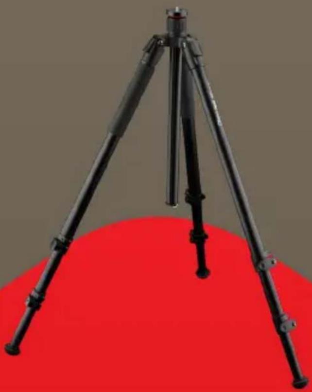
Black tripod with tripod legs and a red base, no visible text or symbolsYou're on steady ground®
Thank You for choosing Oben.
These sturdy, multifeatured Skysill aluminum tripods feature flip locks that let you quickly and effortlessly adjust your tripod's height up to nearly 6 feet while providing several options for low-angle shooting. Skysill models with a 90^ lateral option offer a center column that can be set at a 90^ angle and rotated 360^ around the tripod. This is ideal for shots that require camera positions that aren't available with traditional tripods, like close-up macro or document photography. Each leg can be positioned independently at three locking angles, and a built-in bubble level helps keep the tripod aligned with the horizon—both essential features when working on uneven terrain.
Skysill kits include Oben's BE Series dual-action ballhead that features two locks for independent adjustment of the ball and panoramic base. An Arca-type quick-release plate allows for quickly mounting and swapping cameras, so you'll have the right camera on your tripod and never miss an opportunity to capture the perfect shot.
Note: Images are for illustrative purposes only. Actual products may vary.
Key Features 4-7
Operation 8-17
Interchangeable Feet 8
Leg Length Adjustment 8
Leg Angle Adjustment 9
Center-Column Adjustment 10
Low-Angle Setup 11-13
Reversing the Center Column 11,13
Using the Short Center Column 12
Lateral Setup 14-15
Counterweight 15
The Mounting Plate 16-17
Reversing the Screw 16
Mounting a Head 17
Attaching Accessories 17
Warnings 18
Optional Accessories 18
Specifications 19
Model ALF-6193
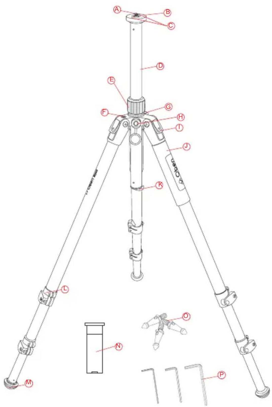
Ⓐ Reversible 3/8-16 and 1/4-20 head mounting screw
B Mounting plate
© Set screws
Reversible center column
E Center column locking collar
F Bubble level
G Strap loop
H 3/8-16 accessory socket
① Leg angle adjustment lock
Rubberized nonslip leg warmers
Retractable and removeable weight hook
Flip-style leg locks
M Removable rubber feet
N Short center column
Spiked feet
P Hex keys (×3)
Model ALF-6113L, ALF-6193L, ALF-6194L
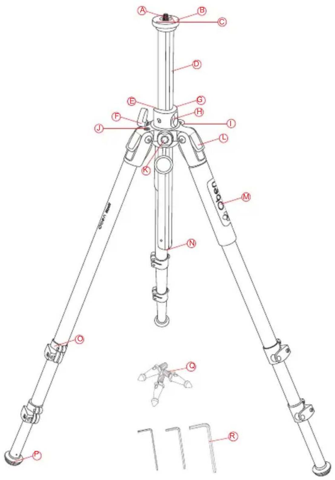
Ⓐ Reversible 3/8-16 and 1/4-20 head mounting screw
B Mounting plate
© Set screws
Reversible center column
⑤ 90° notch
F Center column locking knob
G Lateral rotating ring
H Center column lateral opening
① Strap loop
J Bubble level
K 3/8-16 accessory socket
Leg angle adjustment lock
M Rubberized nonslip leg warmers
N Locking button
Flip-style leg locks
Removable rubber feet
Q Spiked feet
Hex keys (×3)
Interchangeable Feet
The rubber feet that come attached to the tripod are good for hard surfaces like hardwood floors, pavement, or carpet that you don't want to damage with spikes.
Spiked feet are good for soft surfaces where some extra security is needed, like grass-or dirt.
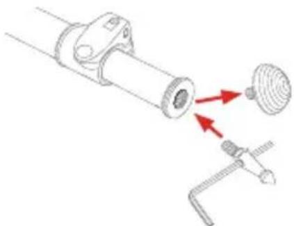
To exchange the rubber feet for the spiked feet:
- Unscrew the rubber feet from the tripod legs.
- Screw in the spiked feet.
- Insert the large hex key through the hole of each foot to tighten it until it's secure.
Leg Length Adjustment
Use the flip locks to adjust the length of the tripod's legs..
To adjust the tension and gripping power of the flip locks, tighten or loosen each flip lock's screw with the included hex key.
Note: When setting up the tripod on an uneven surface, refer to the integrated bubble level to ensure that the mounting plate is straight and aligned with the horizon.
natural_image
Technical diagram of a mechanical assembly with red arrows indicating direction (no text or symbols)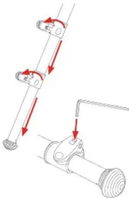
natural_image
Mechanical assembly diagram showing two connected components with red arrows indicating motion direction (no text or symbols)Leg Angle Adjustment
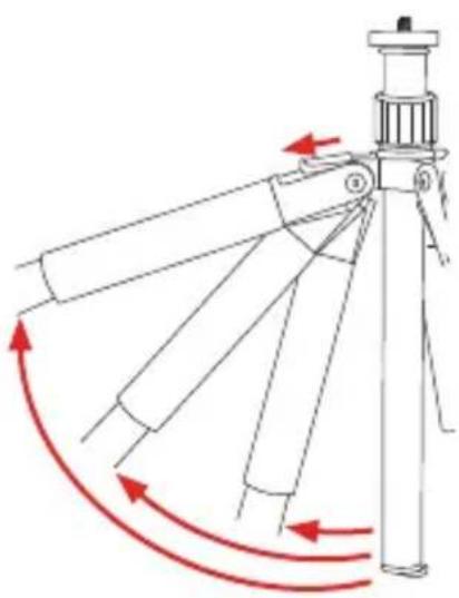
For stable support when shooting on uneven terrain, each tripod leg can be individually set at a preset angle.
To increase the leg angle, do the following:
natural_image
Diagram of a mechanical device with multiple blades and directional arrows indicating motion (no text or symbols)- Slide the adjustment lock in the direction of the arrow. You may need to move the leg so it moves slightly in toward the center in order to move the adjustment lock.
- Set the angle of the leg to one of the three preset positions.
- Release the lock to secure the leg at the desired angle.
To decrease the angle, move the leg in toward the center until the lock clicks on the next preset.
Fully extending the center column and the legs will place the camera at the highest position possible with this tripod.
Center-Column Adjustment
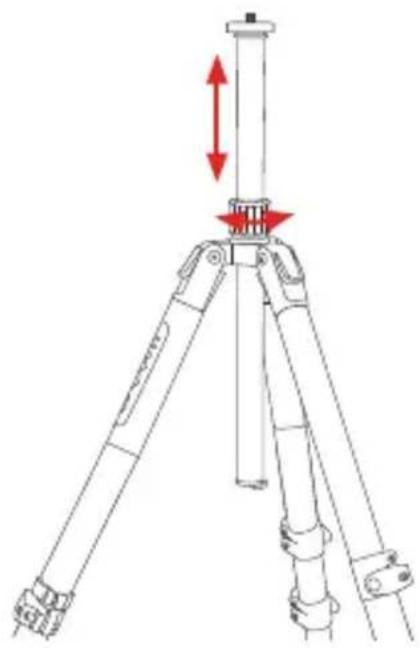
ALF-6193
To adjust the height of the center column, turn the locking collar counterclockwise to disengage the lock, and move the center column to the desired height.
Turn the locking collar clockwise to tighten the lock. Make sure that the lock is adequately tightened to support the weight of the load on the mounting plate.
ALF-6113L, ALF-6193L, ALF-6194L
To adjust the height of the center column, turn the center-column locking knob counterclockwise to disengage the lock, and move the center column to the desired height.
Turn the center-column locking knob clockwise to tighten the lock. Make sure the lock is adequately tightened to support the weight of the load on the mounting plate.
Note: Extending the center column will make the tripod less stable. Extend the legs first, and extend the center column if needed.
natural_image
Technical line drawing of a tripod-mounted device with red directional arrows indicating movement or force (no text or symbols)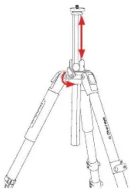
Low-Angle Setup
ALF-6193
The following instructions describe two ways to adjust the tripod for low-angle shots.
REVERSING THE CENTER COLUMN
Reversing the center column allows you to place your camera almost at ground level.
- Remove your camera from the tripod.
- Remove the weight hook from the bottom of the center column by unscrewing it and pulling it out of the center column.
- Loosen the center column's locking collar and pull the center column out of the tripod.
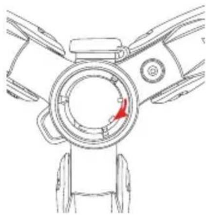
- Reverse the center column, and align the groove on the center column with the guide tabs inside the tripod's ring.
- Reinsert the center column by sliding it up from underneath the tripod and through the center ring. Tighten the locking collar until secure.
- Replace the weight hook by screwing it into the end of the center column.
natural_image
Technical line drawing of a mechanical component with a red arrow indicating a specific feature (no text or symbols present)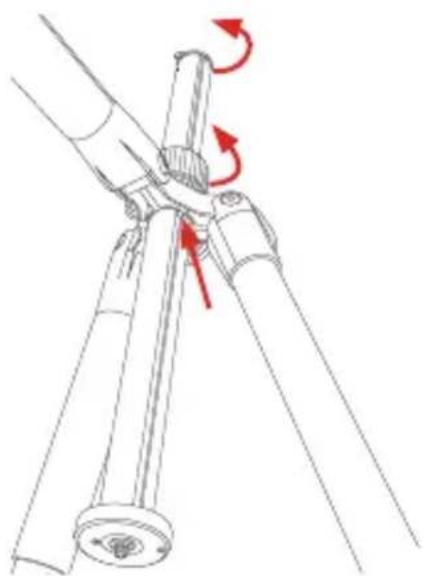
natural_image
Technical line drawing of a mechanical assembly with three rods and a central hub, showing rotational arrows (no text or symbols)Low-Angle Setup (continued)
USING THE SHORT CENTER COLUMN
The short center column allows an extremely wide leg angle for low-angle shots from close to ground level or on uneven terrain.
- Follow steps 1 through 3 in Reversing the Center Column above.
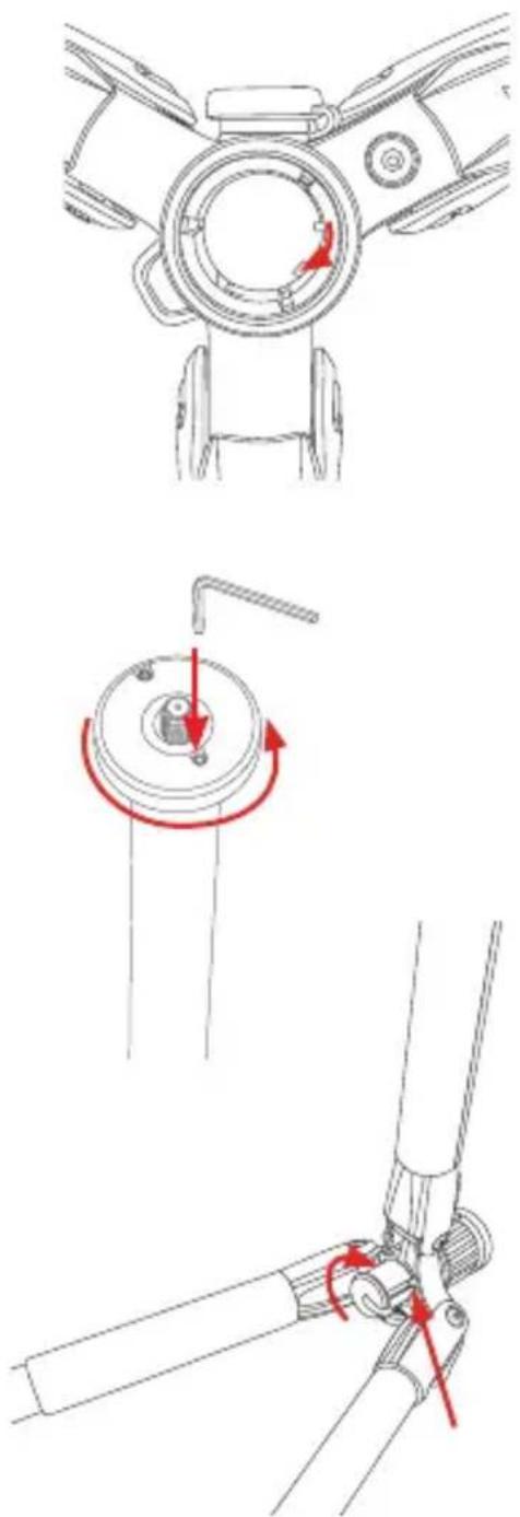
- Align the groove on the short center column with the guide tabs inside the tripod's ring, and slide the center column into the tripod. Tighten the twist lock until secure.
- Remove the mounting plate from the center column. Loosen the top set screw on the mounting plate by turning it counterclockwise with the small hex key. Then unscrew the mounting plate by turning it counterclockwise.
- Screw the mounting plate onto the short center column, and tighten the top set screw until it's secure.
- For extra security, screw the weight hook into the bottom of the short center column after it's installed into the tripod.
natural_image
Technical line drawings of a mechanical assembly with three views showing rotational and linear motion (no text or symbols)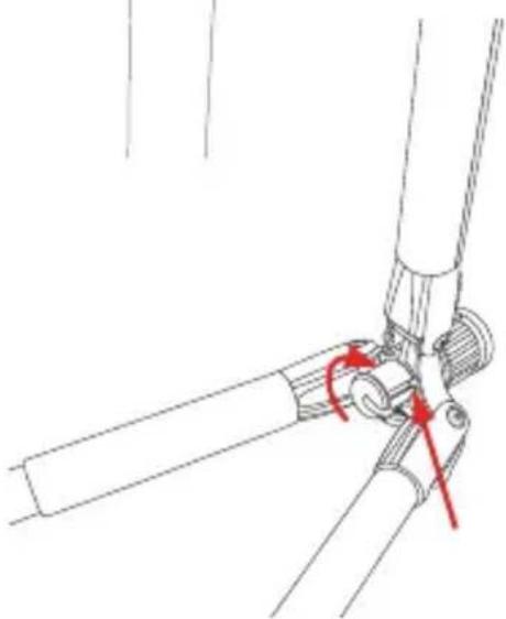
natural_image
Technical line drawing of a mechanical joint or bracket assembly (no text or symbols)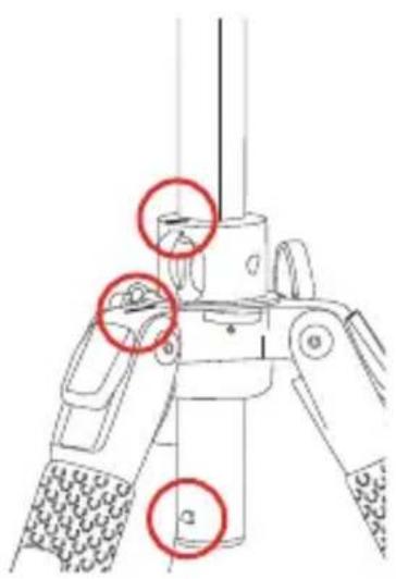
ALF-6113L, ALF-6193L, ALF-6194L
REVERSING THE CENTER COLUMN
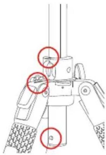
Important! For the Skysill tripod to operate smoothly, several components must be aligned.
This figure shows the correct orientation with the lines at the top of the tripod leg and the lateral rotating ring, and the center column's locking pin are properly aligned.
natural_image
Diagram of a tripod-mounted device with a vertical pole and red directional arrows indicating rotation (no text or symbols)-
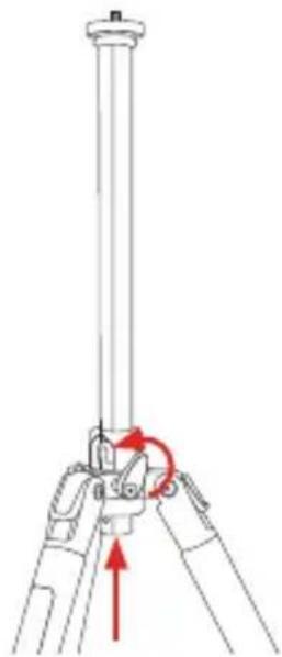
Loosen the locking knob, and raise the center column to its maximum height.
-
While holding the center column with one hand, press the locking button at the bottom of the center column, and raise the center column until it stops.
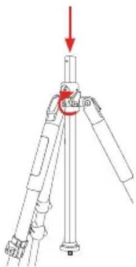
-
Press the locking button again, and pull the center column out of the tripod.
-
Press and hold the center-column locking button while you insert the center column from underneath the tripod.
-
Tighten the center-column lock until secure.
natural_image
Diagram of a tripod-mounted device with a red arrow indicating force or rotation (no text or symbols present)Lateral Setup
ALF-6113L, ALF-6193L, ALF-6194L
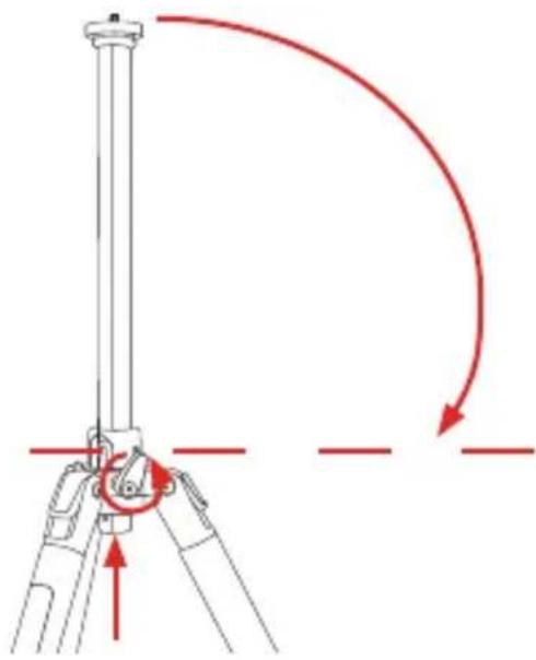
The center column can be set to a 90^ angle and rotated a full 360^ .
Important! When you mount a camera to the tripod in this configuration, make sure to extend the camera over one of the tripod legs. To improve stability, counterweight your tripod as necessary.
-
Loosen the center-column lock, and raise the center column to its maximum height.
-
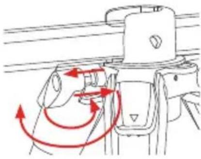
Press the locking button at the bottom of the center column, and raise the center column until it stops. Then lower the center column to the 90° angle.
-
Once the center column is sitting at the 90° angle, slide the center column through the lateral opening until reaching the desired lateral position.
-
Swivel the center column around the tripod as desired.
-
Once the center column is in position, tighten the center-column locking knob until secure.
natural_image
Diagram of a tripod-mounted surveying instrument with red curved arrows indicating motion or direction (no text or symbols)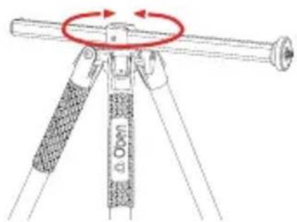
natural_image
Diagram of a mechanical device with red arrows indicating motion or force direction (no text or symbols)Note: The center column locking knob is a spring-loaded ratchet handle. When the center column is blocking the full rotation of the locking knob, turn the lock as far as it will go. Pull it out, reposition it, and let the spring pull it back to reengage it. Continue to tighten or loosen the locking knob.
TO RETURN THE CENTER COLUMN TO THE UPRIGHT POSITION:
- Extend the center column out until it stops.
- Tilt it up until it's vertical, and with the proper alignment, slide it down into the center ring.
- Tighten the center-column lock until secure.
Counterweight
ALF-6193
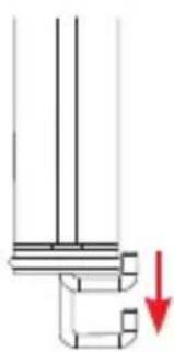
To improve the tripod's stability in windy conditions or when using a telephoto lens, use the built-in spring-loaded hook at the bottom of the center column.
Pull down the hook to hang a counterweight, such as the Impact saddle sandbag or a loaded equipment bag.
natural_image
Pure mechanical assembly diagram showing a pipe connection with a red arrow indicating downward motion (no text or symbols)The Mounting Plate
REVERSING THE SCREW
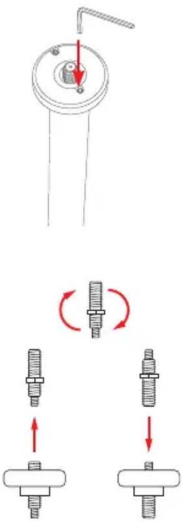
The tripod includes a mounting screw with a 1/4-20 thread on one end and a 3/8-16 thread on the other. This allows you to mount a tripod head with either sized socket.
To switch between the two sizes of mounting screws, follow these steps:
-
Use the smallest hex key to loosen the top set screw on the mounting plate by turning it counterclockwise.
-
Unscrew the mounting plate from the tripod by turning it counterclockwise.
-
Remove the screw, and return the opposite end back into the plate.
-
Screw the mounting plate back into the tripod by turning it clockwise. Make sure the screw is completely seated inside the hole. When switching to the 1/4-20 screw, only the 1/4-20 screw should be visible above the mounting plate.
-
Tighten the set screw until it's secure.
Important! Tighten the set screw until it's snug. Don't overtighten.
MOUNTING A HEAD
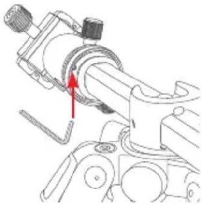
Align the bottom of the head with the tripod's mounting screw, then twist clockwise until fully secured. Do not overtighten, as this may damage the head or the mounting screw.
natural_image
Technical line drawing of a mechanical assembly with a red arrow indicating a specific component (no text or symbols present)The mounting plate is equipped with a set screw, which clamps against the base of the head to prevent unintentional loosening and to ensure the head is securely locked onto the tripod.
Turn the set screw counterclockwise to secure the mounting plate to the head until it's snug. Don't overtighten.
Attaching Accessories
The Skysill tripod is outfitted with a 3/8-16 accessory socket that can be used to add accessories such as an LED light, microphone, monitor, or flash to your tripod setup.

natural_image
Technical line drawing of a tripod-mounted device with a red arrow pointing to a component (no text or symbols present)The 3/8-16 accessory socket is compatible with most articulating and accessory arms. It has an anti-twist design that works best with articulating arms with a similar anti-twist design, such as the Axler Recodo Series of Articulating Arms.

Warnings:
- Do not exceed the tripod's maximum load capacity.
- Ensure that all appropriate locks are engaged when necessary.
- The tripod should be used only in temperatures between -22^ and 140^ (-30°C and 60°C).
- Do not operate in salt water. Dry the tripod off if it becomes wet.
- Remove the camera from the tripod during transport.
- Keep out of reach of children.
- Always support the camera on top of the center column with one hand while adjusting the center column's height.
OPTIONAL ACCESSORIES
Oben Tripod Strap with Quick-Release Loop and Spring Lock
TS-10
TS-100
Oben Deluxe Tripod Strap with Swivel Clip
TS-110
Oben Tripod Strap with Two Quick-Release Loops
TS-20
TS-200
Oben Tripod Hammock
- STB-10
Visit our website at ObenSupports.com for more Oben products.
| ALF-6193 ALF-6113L ALF-6193L ALF-6194L | ||||
| Maximum Height with Center Column Extended | 67 in. (1.7 m) | 64.5 in. (1.6 m) | 67 in. (1.7 m) | 67 in. (1.7 m) |
| Maximum Height w/o Center Column Extended | 53 in. (1.3 m) | 50.5 in. (1.3 m) | 53 in. (1.3 m) | 53 in. (1.3 m) |
| Minimum Height 6 in. (15.2 cm) | 5 in. (12.7 cm) | 4.5 in. (11.4 cm) | 4.2 in. (10.7 cm) | |
| Folded Length 25.5 in. (64.8 cm) | 24 in. (61 cm) | 25.5 in. (64.8 cm) | 21.5 in. (54.6 cm) | |
| Maximum Load 19 lb. (8.6 kg) | 11 lb. (5 kg) | 19 lb. (8.6 kg) | 19 lb. (8.6 kg) | |
| Weight 4.8 lb. | (2.2 kg) | 4.2 lb. (1.9 kg) | 5.1 lb. (2.3 kg) | 5.15 lb. (2.3 kg) |
| Leg Sections | 3 3 3 4 | |||
| Center Column | Standard 90° | Lateral 90° Lateral 90° Lateral | ||
Note: The values in this specification chart reflect only the values of the tripod legs and not the tripod kits.
Oben is a registered trademark of the Gradus Group. © 2020 Gradus Group LLC. All Rights Reserved.
- Skysill Series Aluminum Tripods
- Thank You for choosing Oben.
- Interchangeable Feet
- Leg Length Adjustment
- Leg Angle Adjustment
- Center-Column Adjustment
- ALF-6193
- ALF-6113L, ALF-6193L, ALF-6194L
- Low-Angle Setup
- REVERSING THE CENTER COLUMN
- Low-Angle Setup (continued)
- USING THE SHORT CENTER COLUMN
- Lateral Setup
- TO RETURN THE CENTER COLUMN TO THE UPRIGHT POSITION:
- Counterweight
- The Mounting Plate
- REVERSING THE SCREW
- MOUNTING A HEAD
- Attaching Accessories
- Warnings:
- OPTIONAL ACCESSORIES
Brand : Oben
Model : Skysill ALF-6193
Category : Tripod