
FTRGCR231 - Thermostat JUNG - Free user manual and instructions
Find the device manual for free FTRGCR231 JUNG in PDF.


| Product Type | Floor heating controller |
| Application | Regulating electrical floor heating systems in domestic installations |
| Operating Voltage | AC 230 V~ 50/60 Hz |
| Temperature Setting Range | 10…50 °C (dial numbers 1 to 6) |
| Switching Capacity | 2.3 kW (max. 10 A resistive load) |
| Switching Differential | Approx. 1 K |
| Temperature Reduction (External Time Switch) | Approx. 5 K |
| Red LED Indication | Control unit requests heat (heating mode) |
| Green LED Indication | Temperature reduction activated |
| Protection Type – Control Unit (Housing) | IP 30 (EN 60529) |
| Protection Type – Remote Sensor | IP 67 (EN 60529) |
| Sensor Element | NTC thermistor |
| Sensor Cable | PVC, 2 x 0.75 mm², 4 m length |
| Maximum Sensor Cable Extension | Up to 50 m with 1.5 mm² cable (shielded if near power cables) |
| Operating Temperature – Control Unit | 0…+40 °C |
| Operating Temperature – Remote Sensor | -20…+70 °C |
| Storage Temperature – Control Unit | -25…+70 °C |
| Storage Temperature – Remote Sensor | -20…+70 °C |
| Contact Type | 1 make contact (non-floating) for heating |
| Compliance | DIN EN 60 730 type 1, VDE 0875 / EN 55 014 (radio interference suppression) |
Frequently Asked Questions - FTRGCR231 JUNG
User questions about FTRGCR231 JUNG
0 question about this device. Answer the ones you know or ask your own.
Ask a new question about this device
Download the instructions for your Thermostat in PDF format for free! Find your manual FTRGCR231 - JUNG and take your electronic device back in hand. On this page are published all the documents necessary for the use of your device. FTRGCR231 by JUNG.
USER MANUAL FTRGCR231 JUNG
Operating Instructions Floor heating controller
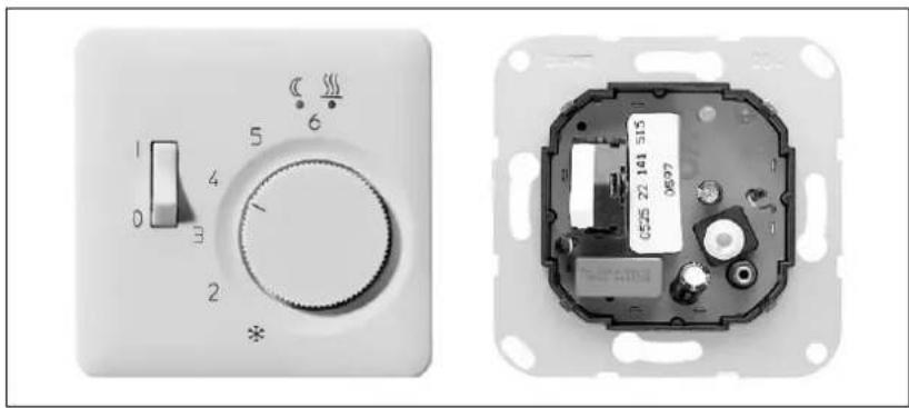
natural_image
Two electronic control panel components: one with a dial and knob, the other showing an internal circuit board (no visible text or symbols)1. Area of application
Used in domestic electrical installations to regulate electrical floor heating systems and temperature control systems.
2. Function
The floor heating controller consists of two parts:
• Control unit for setting the required floor temperature
- Remote sensor in the floor for monitoring the set temperature
Control unit:
Using the setting knob, set the required temperature for your floor. The numbers ✉ - 6 on the knob correspond to a temperature range of 10 - 50 °C.
Note the setting instructions from the manufacturer of your floor heating system.
If the temperature in the floor falls below the temperature you have set, the control unit requests heat; this state is displayed by the red LED above the setting knob. You can therefore see if your heating is using energy.
A range restriction can also be carried out in the setting knob.
The operating state of your floor heating is switched on or off with the mains switch 0 - 1.
You also have the option of programming a temperature reduction via an external time switch e.g. during the night.
If you have installed this type of time switch, the temperature reduction is indicated by the green LED above the setting knob. The temperature reduction is approx. 5 °C.
Example: The temperature set by you on the control unit is 34 ^ (number on dial = 4). This means that the temperature in the floor e.g. during the night can drop down to 29 ^ without your heating switching itself on.
Sensor:
The sensor is to be installed in the floor. It monitors the floor temperature set on the control unit and issues commands to switch the floor heating on and off.
Safety instructions
Electrical equipment may only be installed and fitted by qualified electricians while observing the current accident prevention regulations.
Non-observance of the safety warnings or installation instructions may damage the device, cause fire or other hazards. In the event of a fault, mains potential can be present at the sensor.
① The switch 0 – I on the control unit causes a singlepole disconnection of the device from the mains and interrupts the circuit to the heating resistor in the floor.
① When working on the load circuit, the mains voltage must be disconnected in principle.
① When the sensor is interrupted, the relay contact is closed. If the sensor experiences a short circuit, the relay contact is open.
3. Connection and installation
Control unit
Mount the control unit in a switch box in accordance with DIN 49 073.
Notice! The device must always be mounted with its supporting frame on top of the wallpaper!
- Carry out the electrical connection according to the wiring diagram (Fig. (1)). Solid conductor cross-section: 1 to 2.5 mm2 No PE conductor required. PE conductor is only used for looping through. Protection class II can be achieved through appropriate installation measures.
Abb.1
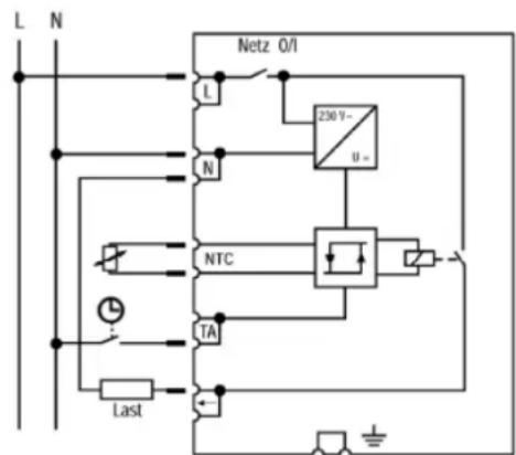
Symbols used in the wiring diagram
L : L conductor
Temperature Management Floor heating controller
Ref.-no.: FTR..231 ..
N : N conductor
TA : Connection for clock signal for temperature reduction
← : Load connection
NTC : Connection for remote sensor
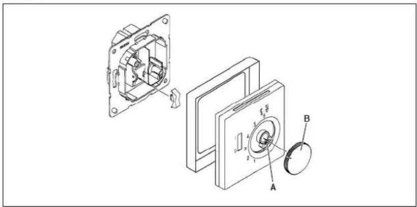
- Mount the control unit with the screws supplied.
- Place the center plate together with the frame on the flush insert. The center plate must snap in place in the top left of the housing base.
- Tighten the screw (A in Fig. (2)).
- Clip on the setting knob (B).
Abb.2
4. Sensor
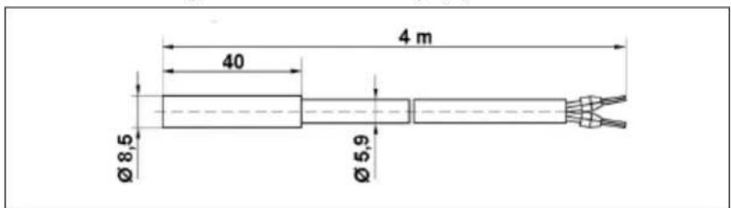
The sensor must be laid in a conduit. It is thereby protected against damp and can easily be replaced in the event of a repair.
Dimension drawing of remote sensor: Fig. (3).
5. Restricting the temperature setting range
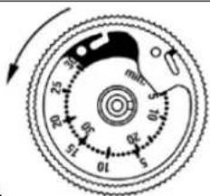
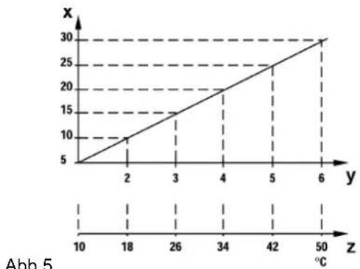
The controller is set ex works to the maximum setting range of to 6. There are 2 adjustment rings (Fig. (4)) in the setting knob which have a setting range of 5 to 30 °C. When restricting the range, we ask you to carry out the setting according to the diagram (Fig. (5)):
Temperature Management Floor heating controller
Ref.-no.: FTR..231 ..

b.4
line
| z (°C) | x | |---|---| | 10 | 5 | | 18 | 10 | | 26 | 15 | | 34 | 20 | | 42 | 25 | | 50 | 30 |Abb.5
x = restricting the range in the setting knob y = setting range of the controller z = sensor temperature °C
6. Technical data
The controller corresponds to DIN EN 60 730 type 1 and has radio interference suppression in accordance with VDE 0875 or EN 55 014.
6.1. Control unit
Operating voltage AC 230 V\~ 50/60 Hz
Temperature setting range
(dial)
※ ...6 (= 10 ... 50 °C)
Switching current
Switching capacity 2.3 kW
Red LED Control unit requires heat (heating mode)
Green LED Temperature reduction "on"
Contact (relay) 1 make contact (for heating), (non-floating)
Temperature reduction (TA) approx. 5 K
Differential in switching
temperature approx. 1 K
Protection type of housing
acc. to EN 60529 IP 30
Operating temperature 0...+40 °C
Storage temperature -25...+70 ^
6.2. Remote sensor
Sensor element NTC
Sensor cable PVC, 2 x 0.75 mm², 4 m
Protection type acc. to
EN 60529 IP 67
Operating temperature -20...+70^
Storage temperature -20+70^
Subject to change without further notice.
The sensor cable can be extended up to 50 m if required using a 2-core cable with a cross-section of 1.5 mm ^2 , without influencing the accuracy of the controller.
When laying in cable trunking or in the vicinity of power cables, a shielded cable should be used.
6.3. Sensor characteristic values
Measuring device Ri > 1 MΩ
Ratio temperature to resistance: see table in Fig (6).
The resistance values can only be measured with a disconnected sensor.
Temperature °C Resistor kΩ
| 05 | 85,279 |
| 10 | 66,785 |
| 15 | 52,330 |
| 20 | 41,272 |
| 25 | 33,000 |
| 30 | 26,281 |
| 35 | 21,137 |
| 40 | 17,085 |
| 45 | 13,846 |
| 50 | 11,277 |
The resistance values can only be measured with a disconnected sensor.
7. Guarantee
Our products are under guarantee within the scope of the statutory provisions.
Please return the unit postage paid to our central service department giving a brief description of the fault:
ALBRECHT JUNG GMBH & CO. KG
Service-Center
Kupferstr. 17-19
D-44532 Lünen
Service-Line: 0 23 55 . 80 65 51
Telefax: 0 23 55 . 80 61 89
CE The CE sign is a free-trade mark intended solely for state authorities and does not contain any assurance of properties.
- Operating Instructions Floor heating controller
- Area of application
- Function
- Control unit:
- Sensor:
- Safety instructions
- Connection and installation
- Control unit
- Temperature Management Floor heating controller
- Sensor
- Restricting the temperature setting range
- Technical data
- Control unit
- Remote sensor
- Sensor characteristic values
- Guarantee
Brand : JUNG
Model : FTRGCR231
Category : Thermostat