
BG-BPTZ - Video Conferencing System BZBGear - Free user manual and instructions
Find the device manual for free BG-BPTZ BZBGear in PDF.

| Product Type | Video Conferencing System |
| Model | BG-BPTZ (3X or 10X optical zoom variant) |
| Image Sensor | 1/2.9-inch high quality HD CMOS, 2.07 megapixels |
| Video Output | USB 2.0 (UVC), supports H.264/H.265/MJPG up to 1920x1080@30fps; YUY2 up to 1280x720@10fps |
| Optical Zoom | 3X (f=3.35~10.05mm) or 10X (f=4.34~41.66mm) depending on model |
| Pan Range | -170° to +170° |
| Tilt Range | -30° to +30° |
| Pan Speed | 0.1~60°/sec |
| Tilt Speed | 0.1~40°/sec |
| Preset Positions | 255 total (10 via remote control) |
| Control Interfaces | RS232 (in/out), RS485, USB 2.0 |
| Control Protocols | VISCA, Pelco-D, Pelco-P (auto-detect) |
| Power Supply | DC 12V, 0.42A max, 5W max consumption |
| Dimensions (W×H×D) | 156.8 mm × 112.6 mm × 139.5 mm |
| Weight | 1 kg |
| Operating Temperature | -10°C to +50°C |
| Storage Temperature | -40°C to +70°C |
| Operating Humidity | 20% to 80% |
| Accessories Included | Power adapter, USB 2.0 cable, IR remote, user manual, warranty card, rubber pad |
| Optional Accessories | Wall mount bracket, ceiling mount bracket |
| Warranty | 3 years standard, extendable to 5 years with registration |
Frequently Asked Questions - BG-BPTZ BZBGear
User questions about BG-BPTZ BZBGear
0 question about this device. Answer the ones you know or ask your own.
Ask a new question about this device
Download the instructions for your Video Conferencing System in PDF format for free! Find your manual BG-BPTZ - BZBGear and take your electronic device back in hand. On this page are published all the documents necessary for the use of your device. BG-BPTZ by BZBGear.
USER MANUAL BG-BPTZ BZBGear
natural_image
Black BZB2 Gear camera with lens and support bracket (no visible text or symbols on device body)Electrical Safety
Installation and operation must conform with local electric safety standards.
Use care when moving
Avoid stress, vibration and moisture in transportation, storage and installation.
Polarity of power supply
The power supply of the product is ±12V , the max electrical current is 2A. Polarity of the power supply drawing.

natural_image
Technical line drawing of a mechanical connector or connector (no text or symbols)Use Caution During Installation
Never move the camera by seizing the camera head. Never rotate the camera head by hand as mechanical damage may occur. Damage due to mishandling will void your warranty.
This unit must be installed on a smooth and level surface. Unit will not display level image if installed in a non-level position.
Ensure the base is solidly secured to the mounting surface.
Avoid using corrosive or abrasive materials to clean the camera as these may damage the finish.
Ensure that the camera is free of obstacles throughout its range of rotation.
Never power on before installation is completed.
Do not disassemble or open the housing. This will void your warranty!
To prevent the risk of electric shock, do not open the case. Installation and maintenance should only be carried out by qualified technicians. There are no serviceable parts inside the camera. BZB Gear is not responsible for any damage due to unauthorized disassembly.
Content
- QUICK INSTALLATION .... 3
1.1 CAMERA INTERFACE EXPLANATION 3
1.2 POWER ON INITIAL CONFIGURATION .... 3
1.3 VIDEO OUTPUT .... 3
2. PRODUCT OVERVIEW 6
2.1 PRODUCT INTRODUCTION 6
2.1.1 Dimensions....6
2.1.2 Accessories....7
2.2 MAIN FEATURES 7
2.3 TECHNICAL SPECIFICATION 8
2.4 INTERFACE INSTRUCTION....9
2.4.1 External Interface 9
2.4.2 RS-232 Interface 10
3. OPERATING INSTRUCTIONS....11
3.1 VIDEO OUTPUT ....11
3.1.1 Power-On Initial Configuration....11
3.1.2 Video Output....11
3.2 Remote Control....12
3.2.1 Keys Instruction 12
3.2.1 KEYS INSTRUCTION.... 12
3.2.2 Applications....12
3.3 MENU SETTING....14
3.3.1 Main Menu....14
3.3.2 System Setting 15
3.3.3 Camera Setting 15
3.3.4 P/T/Z....19
3.3.5 Version....19
3.3.6 Restore Default....20
4.SERIAL COMMUNICATION CONTROL 20
4.1 VISCA PROTOCOL LIST 21
4.1.1 Camera return command.... 21
4.1.2 Camera control command.... 21
4.1.3 Inquiry command 24
4.2 PELCO-D PROTOCOL COMMAND LIST 26
4.3 PELCO-P PROTOCOL COMMAND LIST....26
5. CAMERA MAINTENANCE AND TROUBLESHOOTING 27
5.1 CAMERA MAINTENANCE....27
5.2 TROUBLESHOOTING 27
6. TECH SUPPORT....28
7.WARRANTY 28
MISSION STATEMENT 29
1. Quick Installation
1.1 Camera Interface Description


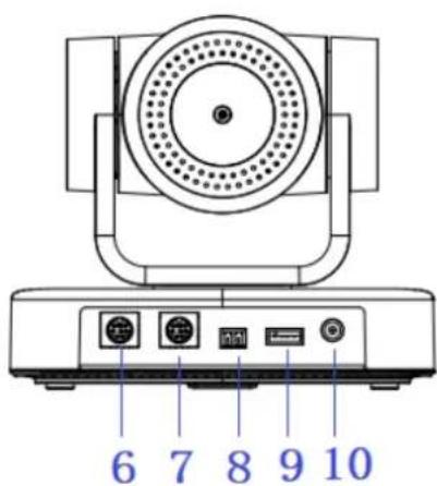
Figure 1.1 Interface
- Camera Lens
- Remote Controller Receiver Light
- Camera Base
- Tripod Screw Hole
-
Mounting hole
-
RS232 Control Interface (output)
- RS232 Control Interface (input)
- RS485 Input (left +, right-)
- USB2.0 Interface
- DC12V Input Power Supply Socket
1.2 Power on initial configuration
1) Power on: Connect DC12V power supply adapter with power supply socket.
2) Initial configuration: Power on with power indicator light on and remote control receiver light blinking, camera head moves from bottom left to the bottom, and then goes to the HOME position (intermediate position of both horizontal and vertical), while the camera module stretches. When remote control receiver light stops blinking, the self-checking is finished
Note: If you set preset 0, when Power on self-test is completed, the camera automatically moves to the preset 0 position.
1.3 Video Output
This model supports USB2.0 video output.
Connect camera and computer by USB2.0 cable, choose video conference software for image.
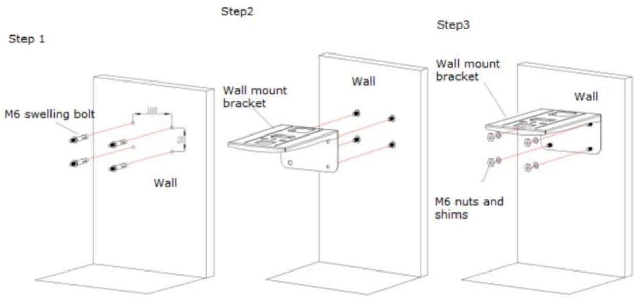
1.4 Bracket mount
Note: Bracket can only be wall mounted or upside-down mounted on template and concrete wall; cannot be installed on plasterboard.
1) Wall mount step


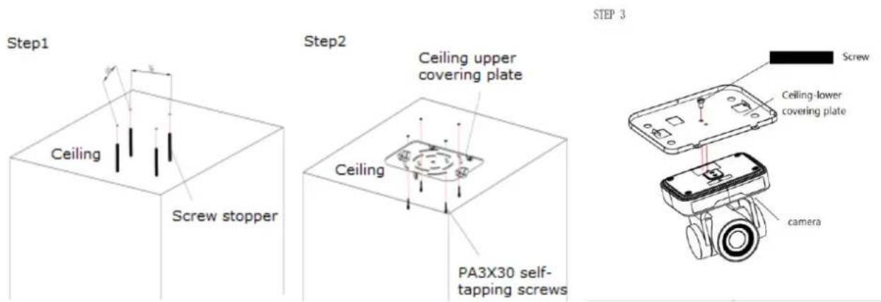
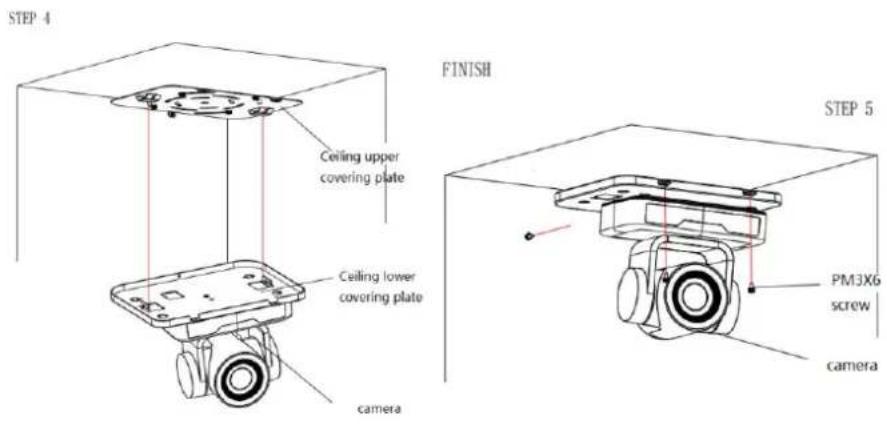
natural_image
Technical line drawing of a mechanical assembly mounted on a wall, labeled 'FINISH' (no other text or symbols)2). Upside down mount step

2. Product overview
2.1 Product Introduction
2.1.1 Dimensions

Figure 2.2 Camera dimension
2.1.2 Accessories
When you unpack, check that all the supplied accessories are included:
| Model No | Configuration | Accessories |
| BG-BPTZ-3XU BG-BPTZ-10XU | Standard | Power adapter 1 piece |
| USB2.0 cable 1 piece | ||
| User manual 1 piece | ||
| IR Remote controller 1 piece | ||
| Rubber pad | ||
| Warranty card 1 piece | ||
| Optional | Wall mount bracket | |
| Ceiling mount bracket |
USB2.0 Video cable: If need USB2.0 cable to provide power but not a power adapter, USB2.0 Video cable with two ports is needed, among which red port is for power supply and black port for transmitting USB video signals. If using a power adapter, the general USB2.0 video cable without power supply function is ok.
2.2 Main Features
- This camera offers superior performance and rich interfaces. The features include advanced ISP processing algorithms to provide vivid images with a strong sense of depth, high resolution and accurate color rendition. It supports H.265/H.264 encoding which makes motion video fluent and clear even with less than ideal bandwidth conditions.
- Superb High-definition Image: This camera employs 1/2.9-inch high quality CMOS sensor. Resolution is up to 1920x1080 with frame rate up to 30 fps.
● Optical Zoom Lens: Camera has a 10X optical zoom lens.
● Leading Auto Focus Technology: Leading auto focus algorithm allow for fast, accurate and stable auto-focusing.
● Low Noise and High SNR: Low Noise CMOS effectively ensure high SNR of camera video.
● Control Interface: RS485, RS232, RS232 supports cascade function for convenient installation.
● Supports Multiple Control Protocol: Supports VISCA, PELCO-D, PELCO-P protocols which can also be automatically recognized. - Quiet PTZ: By adopting high accuracy step driving motor mechanism, it works extremely quiet and moves smoothly and very quickly to designated position.
● 255 Presets Positions: Up to 255 presets (10 presets by remoter). - Wide Application: Tele-education, Lecture capture, Webcasting, Videoconferencing, Tele-training, Tele-medicine, Interrogation, and Emergency command systems.
2.3 Technical Specification
| Model | 3X | 10X |
| Camera Parameter | ||
| Sensor | 1/2.9-inch high quality HD CMOS sensor | |
| Effective Pixels | 2.07 megapixel, 16:9 | |
| Video Format | H264/H265/MJPG:1920*1080P@30/25/20/15/10/5fps; 1280*720P@30/25/20/15/10/5fps;960*540@30/25/20/15/10/5fps; 800*600@30/25/20/15/10/5fps;720*576@30/25/20/15/10/5fps; 720*480@30/25/20/15/10/5fps;640*480@30/25/20/15/10/5fps; 640*360@30/25/20/15/10/5fps;352*288@30/25/20/15/10/5fps; 320*240@30/25/20/15/10/5fps;YUY2:1280*720@10/5fps; 800*600@10/5fps; 640*480@30/25/20/15/10/5fps;640*360@30/25/20/15/10/5fps; | |
| View Angle | 34.1°~85° | 8.8°~66° |
| F Value | f=3.35mm~10.05mm | f=4.34mm~41.66mm |
| AV | F1.7~3.0 | F1.85-F2.43 |
| Optical Zoom | 3X | 10X |
| Minimum Illumination | 0.5Lux (F1.8, AGC ON) | |
| DNR | 2D & 3D DNR | |
| White Balance | Auto / Manual/ One Push/ (2400K~7100K) | |
| Focus | Auto/Manual | |
| Aperture | Auto/Manual | |
| BLC | one/off | |
| Video adjustment | Brightness, Color, Saturation, Contrast, Sharpness, B/W mode, Gamma curve | |
| SNR | >55dB | |
| Input/Output Interface | |
| Video Interfaces | USB2.0 (type A) |
| Video Compression Format | YUY2, MJPG, H.264, H.265 |
| Control Signal Interface | RS232, RS485 |
| Control Protocol | VISCA/Pelco-D/Pelco-P; |
| Power Interface | HEC3800outlrt (DC12V) |
| USB Features | |
| Operating system | Windows 7, Windows8, Windows10, Mac osx, Linux |
| Video Compression Format | MJPG/H264/H265 |
| USB common protocol | UVC |
| PTZ Parameter | |
| Pan Rotation | -170°~+170° |
| Tilt Rotation | -30°~+30° |
| Pan Control Speed | 0.1 ~60°/sec |
| Tilt Control Speed | 0.1~40°/sec |
| Preset Speed | Pan: 48°/sec, Tilt: 38°/sec |
| Preset Number | 255 presets (10 presets by remote controller) |
| Other Parameter | |
| Input Voltage | 12V |
| Input Current | 0.42A(max) |
| Consumption | 5W(max) |
| Store Temperature | -40°C~+70°C |
| Store Humidity | 20%~90% |
| Working Temperature | -10°C~+50°C |
| Working Humidity | 20%~80% |
| Dimension | 156.8mm×112.6mm×139.5mm |
| Weight | 1kg |
| Working Environment | Indoor |
| Accessory | Power Supply, Remote Controller, USB2.0 cable, Manual ,Warranty card, Packing list |
| Optional Accessory | Bracket |
2.4 Interface Instruction
2.4.1 External Interface
1) External interface: RS232 in \out, USB2.0, A-in, DC12V
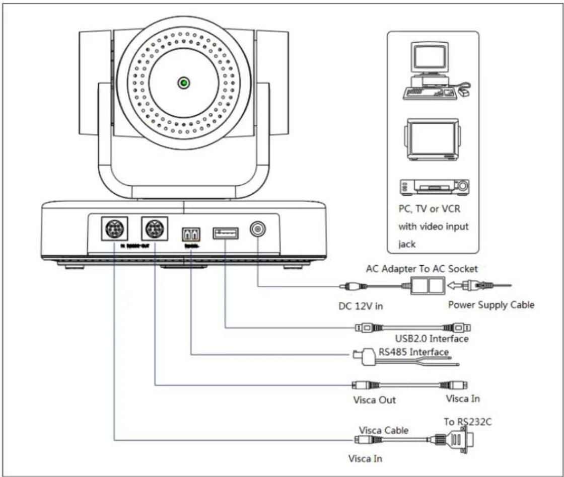
Figure 2.4 external interface diagram
2.4.2 RS-232 Interface
1)RS-232 Interface
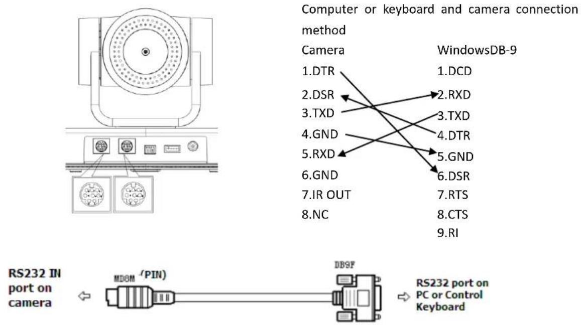
2)RS-232 Mini-DIN 8-pin Port Definition
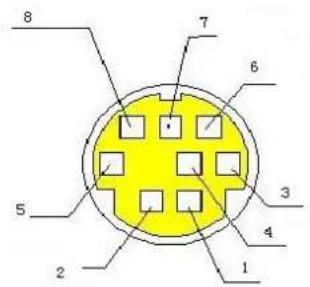
| NO. | Port | Definition |
| 1 | DTR | Data Terminal Ready |
| 2 | DSR | Data Set Ready |
| 3 | TXD | Transmit Data |
| 4 | GND | System Ground |
| 5 | RXD | Receive Data |
| 6 | GND | System Ground |
| 7 | IR OUT | IR Commander Signal |
| 8 | NC | No Connection |
3)RS232(DB9) Port Definition
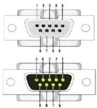
| NO. | Port | Definition |
| 1 | DCD | Data Carrier Detect |
| 2 | RXD | Receive Data |
| 3 | TXD | Transmit Data |
| 4 | DTR | Data Terminal Ready |
| 5 | GND | System Ground |
| 6 | DSR | Data Set Ready |
| 7 | RTS | Request to Send |
| 8 | CTS | Clear to Send |
| 9 | RI | Ring Indicator |
4) VISCA networking as shown below:

flowchart
graph TD
    A["VISCA Controller"] --> B["VISCA Equipment"]
    B --> C["IN OUT"]
    B --> D["IN OUT"]
    B --> E["IN OUT"]
    C --> F["Computer"]
    D --> G["Computer"]
    E --> H["Computer"]
Camera cascade connection method
Camera1
1.DTR
2.DSR
3.TXD
4.GND
5.RXD
6.GND
7.IR OUT
- NC

Camera 2
1.DTR
2.DSR
3.TXD
4.GND
5.RXD
6.GND
7.OPEN
8.OPEN
Note: this model has RS232 input and output interface, so you can cascade as the above way.
3. Operating Instructions
3.1 Video Output
3.1.1 Power-On Initial Configuration
After connecting the power, the camera will initiate self-test mode. The IR indicator light will start flashing. When the camera returns to the HOME position (middle position for P/T) and lens finishes zoom in/out, the self-testing is finished. The IR led will stop flashing. If the preset 0 is set, the camera will rotate to the (0) preset position after initial configuration.
3.1.2 Video Output
Connect the video output cable according to the interface diagram.
USB2.0 output: Connect this product with computer USB3.0 interface (blue), open the Device Manager to see whether there is an image device and whether the Universal Serial Bus controllers recognize USB3.0 device. After the computer identifies the device an image will be displayed.
3.2 Remote Control
3.2.1 Keys Instruction
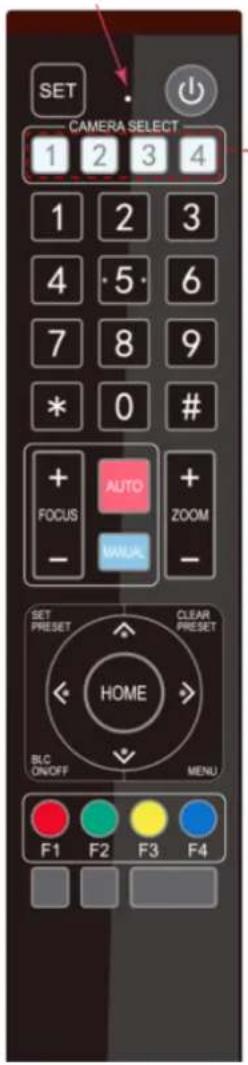
3.2.1 Key Description
1. Power/Standby Key
Press and hold for 3 seconds to place the camera into standby mode. Press and hold for 3 seconds a second time and the camera will self-test again and return to the HOME position. Note: Camera will default to preset 0 if no command is sent within 12 seconds of power on.
2. Camera Select
Select the ID of the camera you wish to control.
3. Number Key
Set or run preset 0-9
4,\* # Key
Used for command modifiers
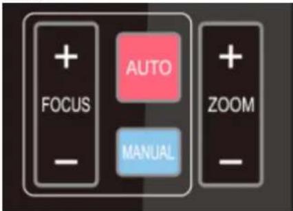
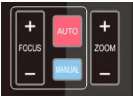
5. Focus Control Key
Auto: Activate auto focus mode.
Manual: Activate manual focus mode.
+/-: Adjust focus in manual focus mode.
6. Zoom Control Key
Zoom+: Zoom In
Zoom—: Zoom Out
7. Set or Clear Preset key:
Set Preset: Press and hold while selecting desired number key to record a preset.
Clear Preset key: Press and hold while selecting desired number key to clear a preset.
8. Pan/Tilt Control Key
▲ Tilt camera up
▼ Tilt camera down
Pan camera left
Pan camera right
HOME: Return to the middle position/ confirm on-screen menu selection.
9. BLC ON/OFF
Turn on or off remote control button backlighting.
10. MENU
Enter or exit on-screen menu/previous menu.
11. Camera IR Remote Control Address Setting
【*】+【#】+【F1】:Camera Address No.1
【*】+【#】+【F2】:Camera Address No. 2
【*】+【#】+【F3】:Camera Address No. 3
【*】+【#】+【F4】:Camera Address No. 4
3.2.2 Applications
Following initialization, the camera can receive and execute the IR commands. The indicator will flash when the camera receives a command. Users can control the pan/tilt/zoom, settings, and run preset positions via the IR remote controller.
Key Instruction:
-
In this instruction, "press the key" means a click rather than a long-press, and a special note will be given if a long-press for more than one second is required.
-
When a key-combination is required, do it in sequence. For example, “【*】+【#】+【F1】” means press“【*】” first and then press“【#】” and last press“【F1】”.
1) Camera Selection

2) Pan/Tilt Control

3) Zoom Control
4) Focus Control
5) BLC Setting

Select the camera address to control.
Up:
press

Down:
press

Left:
press

Right:
press

Back to middle position: press"【HOME】"
Press and hold the up/down/left/right key, the pan/tilt will keep running, from slow to fast, until it runs to the endpoint; the pan/tilt running stops as soon as the key is released.
ZOOM IN: press "ZOOM" key
ZOOM OUT: press "ZOOM" key
Press and hold the key, the camera will keep zooming in or zooming out and stops as soon as the key is released.
Focus (near): Press "【focus+】" key (Valid only in manual focus mode)
Focus (far): Press "【focus-】"key (Valid only in manual focus mode)
Auto Focus: Support
Manual Focus: Support
Press and hold the key, the action of focus will keep continue and stops as soon as the key is released.
BLC ON / OFF: support
6) Presets Setting, Running, Clearing
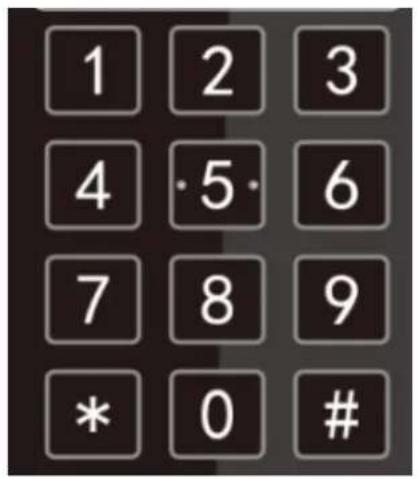

7) Camera Remote Controller Address Setting

- Preset setting: to set a preset position, the users should press the "【SET PRESET】" key first and then press the number key 0-9 to set a relative preset,
Note: 10 preset positions in total are available by remote controller.
- Preset Running: Press a number key 0-9 directly to run a relative preset.
Note: Action in vain if a relative preset position is not existed.
- Preset clearing: to clear a preset position, the user can press the "【CLEAR PRESET】" key first and then press the number key 0-9 to clear the relative preset;
Note : press the“【#】” key three times continually to cancel all the presets.
【*】+【#】+【F1】:Camera Address No.1
【*】+【#】+【F2】:Camera Address No. 2
【*】+【#】+【F3】:Camera Address No. 3
In normal working mode, press 【MENU】key to display the menu, using scroll arrow to point at or highlight the selected items.
![MENU ===================== (Setup) (Camera) (P/T/Z) (Version) (Restore Default) [↑↓]Select [←→]Change Value [Menu]Back[Home]OK](/content/2026/06/1167174/images/7071804b25586789a2aaa4f45b0b0d3ca7de317705841193a84409bc9c6865dc.jpg)
SETUP: System setting
CAMERA : Camera setting
P/T/Z: Pan tilt setting
VERSON: camera version setting
Restore Default: Reset setting
[↑↓] Select: for selecting menu
[← →] Change Value: for modify parameters
[MENU] Back: Press [MENU] to return
[Home] OK: Press [Home] to confirm
3.3.2 System Setting
Move the pointer to the (Setup) in the Main Menu, click the【HOME】key and enter into the (System Setting) as shown below,
| SETUP | |
| Protocol | Auto |
| Visca Address | 1 |
| Visca Address Fix | OFF |
| PELCO-P Address | 1 |
| PELCO-D Address | 1 |
| Baudrate | 9600 |
| Auto Filp | ON |
| [↑↓]Select [←→]Change Value | |
PROTOCOL: VISCA/Pelco-P/Pelco-D/Auto
VISCA ADDRESS: VISCA=1\~7 Pelco-P=1\~255 Pelco-D = 1\~255
BAUD RATE : 2400/4800/9600/115200
VISCA ADDRESS FIX : On/Off
3.3.3 Camera Setting
Move the pointer to the (CAMERA) in the Main Menu, click the 【HOME】 key and enter the (CAMERA) as follow:
CAMERA
(Exposure)
(Color)
(Image)
(Focus)
(Noise Reduction)
Style
Default
[↑ ↓ ]Select
[← →]Change Value
[Menu]Back
[Home]OK
EXPOSURE: Enter Exposure setting
COLOR: Enter color setting
Image: Enter image setting
Focus: Enter focus setting
Noise Reduction: Enter noise reduction
1) EXPOSURE SETTING
Move the pointer to the (EXPOSURE) in the Main Menu, click the 【HOME】 and enter the (EXPOSURE SET) as follow,
EXPOSURE
Mode
Auto
EV
OFF
BLC
OFF
Flicker
50Hz
G.Limit
3
DRC
2
[↑ ↓]Select
[← →]Change Value
[Menu]Back
Mode: Auto, Manual, Shutter priority, Iris priority and Brightness priority.
EV: On/Off (only available in auto mode)
Compensation Level: -7\~7 (only available in auto mode when EV is ON)
BLC: ON/OFF for options (only available in auto mode)
Anti-Flicker: OFF/50Hz/60Hz for options (only available in Auto/Iris priority/Brightness priority modes)
Gain Limit: 0\~15(only available in Auto/ Iris priority /Brightness priority mode)
WDR: Off,1\~8
Shutter
Priority:1/25,1/30,1/50,1/60,1/90,1/100,1/120,1/180,1/250,1/350,1/500,1/1000,1/2000,1/3000,1/4000,1/6000,1/10000(only available in Manual and Shutter priority mode)
IRIS Priority: OFF,F11.0,F9.6,F8.0,F6.8,F5.6,F4.8,F4.0,F3.4,F2.8,F2.4,F2.0,F1.8(only available in Manual and Iris priority mode)
Brightness: 0\~23 (only available in Brightness priority mode)
2) COLOR SETTING
Move the pointer to the (COLOR) in the Main Menu, click the 【HOME】 and enter the (COLOR SET) as follow:
COLOR
| WB Mode | Auto |
| RG Tuning | -10 |
| BG Tuning | -10 |
| Saturation | 100% |
| Hue 7 | |
| AWB Sensitivity | High |
[↑ ↓]Select [← →]Change Value
[Menu]Back
WB Mode: Auto, 3000K, 3500K, 4000K, 4500K, 5000K, 5500K, 6000K, 6500K, 7000K, Manual, One Push
Red Gain: 0\~255(only available in Manual mode)
Blue Gain: 0\~255(only available in Manual mode)
Saturation: 60%,70%,80%,90%,100%,110%,120%,130%
Hue: 0\~14
AWB Sensitivity: high/middle/low
Color Style: Default, style1\~4.
Color Temp: high/middle/low
3) IMAGE
Move the pointer to the (IMAGE) in the Menu, click the 【HOME】 and enter the (IMAGE) as follow,
IMAGE
| Brightness | 7 |
| Contrast | 8 |
| Sharpness | 3 |
| Flip-H | OFF |
| Flip-V | OFF |
| B&W-Mode | Color |
| Gamma | Default |
| DCI | Close |
| Low-Light Mode | OFF |
| [↑↓]Select | [←→]Change Value |
| [Menu]Back |
Brightness: 0\~14
Contrast: 0\~14
Sharpness: 0\~15
Flip-H: On/Off
Flip-V: On/Off
B&W Mode: color, black/white
Gamma: default, 0.47, 0.50, 0.52, 0.55
DZoom: digital zoom options: On/Off
DCI: Dynamic Contrast: Off,1\~8
4) FOCUS
Move the pointer to the (FOCUS) in the Menu, click the 【HOME】 and enter the (FOCUS) as follow,
FOCUS
| Focus Mode | Auto | |
| AF-Zone | Center | |
| AF-Sensitivity | Low | |
| [↑↓]Select | [←→]Change | |
| Value | ||
Focus Mode: Auto, manual
AF-Zone: Up, middle, down
AF-Sensitivity: High, middle, low
5) NOISE REDUCTION
Move the pointer to the (NOISE REDUCTION) in the Menu, click the 【HOME】 and enter the (NOISE REDUCTION) as follow,
NOISE REDUCTION
NR-2D
Auto
NR-3D
3
Dynamic Hot Pixel
OFF
[↑ ↓ ]Select
[← →]Change
Value
2D Noise Reduction: Auto, close, 1\~7
3D Noise Reduction: Close, 1\~8
Dynamic Hot Pixel: Close, 1\~5
3.3.4 P/T/Z
Move the pointer to the (P/T/Z) in the Main Menu, click the 【HOME】 and enter the (P/T/Z) as follow,
P/T/Z
Depth of field
ON
Zoom speed
8
Image Freezing
OFF
Acc Curve
Slow
[↑ ↓]Select
[← →]Change
Value
Depth of Field: Only effective for remote controller, On/ Off;
When zoom in, the PT control speed by remoter will become slow),
Zoom Speed: Set the zoom speed for remote controller,1\~8
Image Freezing: On/Off
Accelerating Curve: Fast/slow
3.3.5 Version
Move the pointer to the (VERSION) in the Main Menu, click the 【HOME】 and enter the (VERSION) as follow,
VERSION
| MCU Version | 3.1.0 | 2019-09-26 |
| Camera Version | 1.0.5 | 2019-09-27 |
| AF Version | 1.0.0 | 2019-09-07 |
| [↑↓]Select | [←→]Change Value |
| [Menu]Back | [Home]OK |
MCU Version: Display MCU version information
Camera Version: Display camera version information
AF Version: Display the focus version information
Lens: Display the lens zoom
Move the pointer to the (RESTORE DEFAULT) in the Main Menu, click the 【HOME】 and enter the (RESTORE DEFAULT) as follow,
RESTORE DEFAULT

Restore Default? N O
[↑ ↓]Select [← →]Change
Value
m. 10
Restore default: options: yes/no; after restoring default, the video format will not be restored.
Note: If the address of former remoter is not 1 but another one from 2,3,4, the corresponding camera address will restore to 1 when all parameters or system parameters are restored. User should change the remoter address to be 1 (press No.1 according to the camera so to get normal operation)
4.Serial Communication Control
Under common working conditions the camera can be controlled through RS232/RS485 interface (VISCA), RS232C serial parameter are as follows:
Baud rate: 2400/4800/9600/115200 bits / sec; Start bit: 1; data bits: 8; Stop bit: 1; Parity: None.
After powering on, the camera will perform a self-test. Self-test is finished after the zoom moves to the farthest and then back to the nearest position. If the camera has a "0" preset stored it will return to that position after initialization. At this point, the user can control the camera by the serial commands.
4.1 VISCA protocol list
4.1.1 Camera return command
| Ack/Completion Message | ||
| Command packet | Note | |
| ACK | z0 41 FF | Returned when the command is accepted. |
| Completion | z0 51 FF | Returned when the command has been executed. |
z = camera address + 8
| Error Messages | ||
| Command packet | Note | |
| Syntax Error | z0 60 02 FF | Returned when the command format is different or when a command with illegal command parameters is accepted |
| Command Not Executable | z0 61 41 FF | Returned when a command cannot be executed due to current conditions. For example, when commands controlling the focus manually are received during auto focus. |
4.1.2 Camera control command
| Command | Function | Command packet | Note |
| AddressSet | Broadcast | 88 30 0p FF | p: Address setting |
| IF_Clear | Broadcast | 88 01 00 01 FF | I/F Clear |
| CommandCancel | 8x 21 FF | ||
| CAM_Power | On | 8x 01 04 00 02 FF | Power ON/OFF |
| Off | 8x 01 04 00 03 FF | ||
| CAM_Zoom | Stop | 8x 01 04 07 00 FF | |
| Tele(Standard) | 8x 01 04 07 02 FF | ||
| Wide(Standard) | 8x 01 04 07 03 FF | ||
| Tele(Variable) | 8x 01 04 07 2p FF | p = 0(low) - F(high) | |
| Wide(Variable) | 8x 01 04 07 3p FF | ||
| Direct | 8x 01 04 47 0p 0q 0r 0s FF | pqrs: Zoom Position | |
| CAM_Focus | Stop | 8x 01 04 08 00 FF | |
| Far(Standard) | 8x 01 04 08 02 FF | ||
| Near(Standard) | 8x 01 04 08 03 FF | ||
| Far(Variable) | 8x 01 04 08 2p FF | p = 0(low) - F(high) | |
| Near (Variable) | 8x 01 04 08 3p FF | ||
| Direct | 8x 01 04 48 0p 0q 0r 0s FF | pqrs: Focus Position | |
| Auto Focus | 8x 01 04 38 02 FF | ||
| One Push Mode | 8x 01 04 38 04 FF | ||
| Manual Focus | 8x 01 04 38 03 FF | ||
| CAM_Zoom Focus | Direct | 8x 01 04 47 0p 0q 0r 0s0t 0u 0v 0w FF | pqrs: Zoom Positiontuvw: Focus Position |
| CAM_WB | Auto | 8x 01 04 35 00 FF | |
| 3000K | 8x 01 04 35 01 FF | ||
| 4000k | 8x 01 04 35 02 FF | ||
| One Push mode | 8x 01 04 35 03 FF | ||
| 5000k | 8x 01 04 35 04 FF | ||
| Manual | 8x 01 04 35 05 FF | ||
| 6500k | 8x 01 04 35 06 FF | ||
| 3500K | 8x 01 04 35 07 FF | ||
| 4500K | 8x 01 04 35 08 FF | ||
| 5500K | 8x 01 04 35 09 FF | ||
| 6000K | 8x 01 04 35 0A FF | ||
| 7000K | 8x 01 04 35 0B FF | ||
| CAM_RGain | Reset | 8x 01 04 03 00 FF | Manual Control of R Gain |
| Up | 8x 01 04 03 02 FF | ||
| Down | 8x 01 04 03 03 FF | ||
| Direct | 8x 01 04 43 00 00 0p 0q FF | pq: R Gain | |
| CAM_Bgain | Reset | 8x 01 04 04 00 FF | Manual Control of B Gain |
| Up | 8x 01 04 04 02 FF | ||
| Down | 8x 01 04 04 03 FF | ||
| Direct | 8x 01 04 44 00 00 0p 0q FF | pq: B Gain | |
| CAM_AE | Full Auto | 8x 01 04 39 00 FF | Automatic Exposure mode |
| Manual | 8x 01 04 39 03 FF | Manual Control mode | |
| Shutter priority | 8x 01 04 39 0A FF | Shutter Priority Automatic Exposure mode | |
| Iris priority | 8x 01 04 39 0B FF | Iris Priority Automatic Exposure mode | |
| Bright | 8x 01 04 39 0D FF | Bright mode | |
| CAM_Shutter | Reset | 8x 01 04 0A 00 FF | Shutter Setting |
| Up | 8x 01 04 0A 02 FF | ||
| Down | 8x 01 04 0A 03 FF | ||
| Direct | 8x 01 04 4A 00 00 0p 0q FF | pq: Shutter Position | |
| CAM_Iris | Reset | 8x 01 04 0B 00 FF | Iris Setting |
| Up | 8x 01 04 0B 02 FF | ||
| Down | 8x 01 04 0B 03 FF | ||
| Direct | 8x 01 04 4B 00 00 0p 0q FF | pq: Iris Position | |
| CAM_Gain Limit | Gain Limit | 8x 01 04 2C 0p FF | p: Gain Position |
| CAM_Bright | Reset | 8x 01 04 0D 00 FF | Bright Setting |
| Up | 8x 01 04 0D 02 FF | ||
| Down | 8x 01 04 0D 03 FF | ||
| Direct | 8x 01 04 4D 00 00 0p 0q FF | pq: Bright Position | |
| CAM_ExpComp | On | 8x 01 04 3E 02 FF | Exposure Compensation ON/OFF |
| Off | 8x 01 04 3E 03 FF | ||
| Reset | 8x 01 04 0E 00 FF | Exposure Compensation Amount Setting | |
| Up | 8x 01 04 0E 02 FF | ||
| Down | 8x 01 04 0E 03 FF | ||
| Direct | 8x 01 04 4E 00 00 0p 0q FF | pq: ExpComp Position | |
| CAM_Back Light | On | 8x 01 04 33 02 FF | Back Light Compensation |
| Off | 8x 01 04 33 03 FF | ||
| CAM_WDRStrength | Reset | 8x 01 04 21 00 FF | WDR Level Setting |
| Up | 8x 01 04 21 02 FF | ||
| Down | 8x 01 04 21 03 FF | ||
| Direct | 8x 01 04 51 00 00 00 0p FF | p: WDR Level Position | |
| CAM_NR (2D) | 8x 01 04 53 0p FF | P=0-7 0:OFF | |
| CAM_NR (3D) | 8x 01 04 54 0p FF | P=0-8 0:OFF | |
| CAM_Gamma | 8x 01 04 5B 0p FF | p = 0 - 4 0: Default 1: 0.47 2: 0.503: 0.52 4: 0.55 | |
| CAM_Flicker | OFF | 8x 01 04 23 00 FF | OFF |
| 50HZ | 8x 01 04 23 01 FF | 50HZ | |
| 60HZ | 8x 01 04 23 02 FF | 60HZ | |
| CAM_Aperture | Reset | 8x 01 04 02 00 FF | Aperture Control |
| Up | 8x 01 04 02 02 FF | ||
| Down | 8x 01 04 02 03 FF | ||
| Direct | 8x 01 04 42 00 00 0p 0q FF | pq: Aperture Gain | |
| CAM_Memory | Reset | 8x 01 04 3F 00 pq FF | pq: Memory Number (=0 to 254)Corresponds to 0 to 9 on the Remote Commander |
| Set | 8x 01 04 3F 01 pq FF | ||
| Recall | 8x 01 04 3F 02 pq FF | ||
| CAM_LR_Reverse | On | 8x 01 04 61 02 FF | Image Flip Horizontal ON/OFF |
| Off | 8x 01 04 61 03 FF | ||
| CAM_PictureFlip | On | 8x 01 04 66 02 FF | Image Flip Vertical ON/OFF |
| Off | 8x 01 04 66 03 FF | ||
| CAM_ColorSaturation | Direct | 8x 01 04 49 00 00 00 0p FF | P=0-70:60% 1:70% 2:80% 3:90% 4:100%5:110% 6:120% 7:130% |
| CAM_IDWrite | 8x 01 04 22 0p 0q 0r 0s FF | pqrs: Camera ID (=0000 to FFFF) | |
| SYS_Menu | ON | 8x 01 04 06 06 02 FF | Turn on the menu screen |
| OFF | 8x 01 04 06 06 03 FF | Turn off the menu screen | |
| IR_Receive | ON | 8x 01 06 08 02 FF | IR (remote commander) receive On/Off |
| OFF | 8x 01 06 08 03 FF | ||
| IR_ReceiveReturn | On | 8x 01 7D 01 03 00 00 FF | IR (remote commander) receive message viathe VISCA communication ON/OFF |
| Off | 8x 01 7D 01 13 00 00 FF | ||
| CAM_SettingReset | Reset | 8x 01 04 A0 10 FF | Reset Factory Setting |
| CAM_Brightness | Direct | 8x 01 04 A1 00 00 0p 0q FF | pq: Brightness Position |
| CAM_Contrast | Direct | 8x 01 04 A2 00 00 0p 0q FF | pq: Contrast Position |
| CAM_Flip | OFF | 8x 01 04 A4 00 FF | Single Command For Video Flip |
| Flip-H | 8x 01 04 A4 01 FF | ||
| Flip-V | 8x 01 04 A4 02 FF | ||
| Flip-HV | 8x 01 04 A4 03 FF | ||
| CAM_VideoSystem | Set camera videosystem | 8x 01 06 35 00 0p FF | P: 0~E Video format0:1080P60 8:720P301:1080P50 9:720P252:1080i60 A: 1080P59.943:1080i50 B: 1080i59.944:720P60 C: 720P59.945:720P50 D: 1080P29.976:1080P30 E: 720P29.977:1080P25 |
| Pan_tiltDrive | Up | 8x 01 06 01 VV WW 03 01 FF | VV: Pan speed 0x01 (low speed) to 0x18 (high speed)WW: Tilt speed 0x01 (low speed) to 0x14 (high speed)YYYY: Pan PositionZZZZ: Tilt Position |
| Down | 8x 01 06 01 VV WW 03 02 FF | ||
| Left | 8x 01 06 01 VV WW 01 03 FF | ||
| Right | 8x 01 06 01 VV WW 02 03 FF | ||
| Upleft | 8x 01 06 01 VV WW 01 01 FF | ||
| Upright | 8x 01 06 01 VV WW 02 01 FF | ||
| DownLeft | 8x 01 06 01 VV WW 01 02 FF | ||
| DownRight | 8x 01 06 01 VV WW 02 02 FF | ||
| Stop | 8x 01 06 01 VV WW 03 03 FF | ||
| AbsolutePosition | 8x 01 06 02 VV WW0Y 0Y 0Y 0Y 0Z 0Z 0Z FF | ||
| RelativePosition | 8x 01 06 03 VV WW0Y 0Y 0Y 0Y 0Z 0Z 0Z FF | ||
| Home | 8x 01 06 04 FF | ||
| Reset | 8x 01 06 05 FF | ||
| Pan-tiltLimitSet | Set | 8x 01 06 07 00 0W0Y 0Y 0Y 0Y 0Z 0Z 0Z FF | W:1 UpRight 0:DownLeftYYYY: Pan Limit Position(TBD)ZZZZ: Tilt Limit Position(TBD) |
| Clear | 8x 01 06 07 01 0W07 0F 0F 0F 07 0F 0F 0F FF |
4.1.3 Inquiry command
| Command | Function | Command packet | Note |
| CAM_PowerInq | 8x 09 04 00 FF | y0 50 02 FF | On |
| y0 50 03 FF | Off(Standby) | ||
| CAM_ZoomPosInq | 8x 09 04 47 FF | y0 50 0p 0q 0r 0s FF | pqrs: Zoom Position |
| CAM_FocusAFModelInq | 8x 09 04 38 FF | y0 50 02 FF | Auto Focus |
| y0 50 03 FF | Manual Focus | ||
| y0 50 04 FF | One Push mode | ||
| CAM_FocusPosInq | 8x 09 04 48 FF | y0 50 0p 0q 0r 0s FF | pqrs: Focus Position |
| CAM_WBModelInq | 8x 09 04 35 FF | y0 50 00 FF | Auto |
| y0 50 01 FF | 3000K | ||
| y0 50 02 FF | 4000K | ||
| y0 50 03 FF | One Push Mode | ||
| y0 50 04 FF | 5000K | ||
| y0 50 05 FF | Manual | ||
| y0 50 00 FF | 6500K | ||
| y0 50 06 FF | 6500K | ||
| y0 50 07 FF | 3500K | ||
| y0 50 08 FF | 4500K | ||
| y0 50 09 FF | 5500K | ||
| y0 50 0A FF | 6000K | ||
| y0 50 0B FF | 7000K | ||
| CAM_RGainInq | 8x 09 04 43 FF | y0 50 00 00 0p 0q FF | pq: R Gain |
| CAM_BGainInq | 8x 09 04 44 FF | y0 50 00 00 0p 0q FF | pq: B Gain |
| CAM_AEModelInq | 8x 09 04 39 FF | y0 50 00 FF | Full Auto |
| y0 50 03 FF | Manual | ||
| y0 50 0A FF | Shutter priority | ||
| y0 50 0B FF | Iris priority | ||
| y0 50 0D FF | Bright | ||
| CAM_ShutterPosInq | 8x 09 04 4A FF | y0 50 00 00 0p 0q FF | pq: Shutter Position |
| CAM_IrisPosInq | 8x 09 04 4B FF | y0 50 00 00 0p 0q FF | pq: Iris Position |
| CAM_Gain LimitInq | 8x 09 04 2C FF | y0 50 0p FF | p: Gain Position |
| CAM_BrightPosInq | 8x 09 04 4D FF | y0 50 00 00 0p 0q FF | pq: Bright Position |
| CAM_ExpCompModelInq | 8x 09 04 3E FF | y0 50 02 FF | On |
| y0 50 03 FF | Off | ||
| CAM_ExpCompPosInq | 8x 09 04 4E FF | y0 50 00 00 0p 0q FF | pq: ExpComp Position |
| CAM_BacklightModelInq | 8x 09 04 33 FF | y0 50 02 FF | On |
| y0 50 03 FF | Off | ||
| CAM_WDRStrengthInq | 8x 09 04 51 FF | y0 50 00 00 00 0p FF | p: WDR Strength |
| CAM_NRLevel(2D) Inq | 8x 09 04 53 FF | y0 50 0p FF | P: 2DNRLevel |
| CAM_NRLevel(3D) Inq | 8x 09 04 54 FF | y0 50 0p FF | P:3D NRLevel |
| CAM_FlickerModelInq | 8x 09 04 55 FF | y0 50 0p FF | p: Flicker Settings (0: OFF,1: 50Hz,2:60Hz) |
| CAM_ApertureInq | 8x 09 04 42 FF | y0 50 00 00 0p 0q FF | pq: Aperture Gain |
| CAM_PictureEffectModelInq | 8x 09 04 63 FF | y0 50 00 FF | Off |
| y0 50 04 FF | B&W | ||
| CAM_MemoryInq | 8x 09 04 3F FF | y0 50 0p FF | p: Memory number last operated. |
| SYS_MenuModelInq | 8x 09 06 06 FF | y0 50 02 FF | On |
| y0 50 03 FF | Off | ||
| CAM_LR_ReverseInq | 8x 09 04 61 FF | y0 50 02 FF | On |
| y0 50 03 FF | Off | ||
| CAM_PictureFlipInq | 8x 09 04 66 FF | y0 50 02 FF | On |
| y0 50 03 FF | Off | ||
| CAM_ColorSaturationInq | 8x 09 04 49 FF | y0 50 00 00 00 0p FF | p: Color Gain setting 0h (60%) to Eh (130%) |
| CAM_IDInq | 8x 09 04 22 FF | y0 50 0p FF | p: Gamma ID |
| IR_ReceiveInq | 8x 09 06 08 FF | y0 50 02 FF | On |
| y0 50 03 FF | Off | ||
| IR_ReceiveReturn | y0 07 7D 01 04 00 FF | Power ON/OFF | |
| y0 07 7D 01 04 07 FF | Zoom tele/wide | ||
| y0 07 7D 01 04 38 FF | AF ON/OFF | ||
| y0 07 7D 01 04 33 FF | Camera Backlight | ||
| y0 07 7D 01 04 3F FF | Camera Memory | ||
| y0 07 7D 01 06 01 FF | Pan_titleDriver | ||
| CAM_BrightnessInq | 8x 09 04 A1 FF | y0 50 00 00 0p 0q FF | pq: Brightness Position |
| CAM_ContrastInq | 8x 09 04 A2 FF | y0 50 00 00 0p 0q FF | pq: Contrast Position |
| CAM_FlipInq | 8x 09 04 A4 FF | y0 50 00 FF | Off |
| y0 50 01 FF | Flip-H | ||
| y0 50 02 FF | Flip-V | ||
| y0 50 03 FF | Flip-HV | ||
| CAM_GammaInq | 8x 09 04 5B FF | y0 50 0p FF | p: Gamma setting |
| CAM_VersionInq | 8x 09 00 02 FF | y0 50 ab cdmn pq rs tu vw FF | ab cd : vender ID (0220)mn pq : model ID ST (0950)U3 (3950)rs tu : ARM Versionvw : reserve |
| VideoSystemInq | 8x 09 06 23 FF | y0 50 0p FF | P: 0~E Video format0:1080P60 8:720P301:1080P50 9:720P252:1080i60A: 1080P59.943:1080i50B: 1080i59.944:720P60C: 720P59.945:720P50D: 1080P29.976:1080P30 E:720P29.977:1080P25 |
| Pan-tiltMaxSpeedInq | 8x 09 06 11 FF | y0 50 ww zz FF | ww: Pan Max Speed zz: Tilt Max Speed |
| Pan-tiltPosInq | 8x 09 06 12 FF | y0 50 0w 0w 0w 0w0z Oz Oz Oz Oz FF | www: Pan Position zzzz: Tilt Position |
Note: [X] in the above table indicates the camera address to be operated, [y]=[x+8] .
4.2 Pelco-D protocol command list
| Function | Byte1 | Byte2 | Byte3 | Byte4 | Byte5 | Byte6 | Byte7 |
| Up | 0xFF | Address | 0x00 | 0x08 | Pan Speed | Tilt Speed | SUM |
| Down | 0xFF | Address | 0x00 | 0x10 | Pan Speed | Tilt Speed | SUM |
| Left | 0xFF | Address | 0x00 | 0x04 | Pan Speed | Tilt Speed | SUM |
| Right | 0xFF | Address | 0x00 | 0x02 | Pan Speed | Tilt Speed | SUM |
| Upleft | 0xFF | Address | 0x00 | 0x0C | Pan Speed | Tilt Speed | SUM |
| Upright | 0xFF | Address | 0x00 | 0x0A | Pan Speed | Tilt Speed | SUM |
| DownLeft | 0xFF | Address | 0x00 | 0x14 | Pan Speed | Tilt Speed | SUM |
| DownRight | 0xFF | Address | 0x00 | 0x12 | Pan Speed | Tilt Speed | SUM |
| Zoom In | 0xFF | Address | 0x00 | 0x20 | 0x00 | 0x00 | SUM |
| Zoom Out | 0xFF | Address | 0x00 | 0x40 | 0x00 | 0x00 | SUM |
| Focus Far | 0xFF | Address | 0x00 | 0x80 | 0x00 | 0x00 | SUM |
| Focus Near | 0xFF | Address | 0x01 | 0x00 | 0x00 | 0x00 | SUM |
| Set Preset | 0xFF | Address | 0x00 | 0x03 | 0x00 | Preset ID | SUM |
| Clear Preset | 0xFF | Address | 0x00 | 0x05 | 0x00 | Preset ID | SUM |
| Call Preset | 0xFF | Address | 0x00 | 0x07 | 0x00 | Preset ID | SUM |
| Query Pan Position | 0xFF | Address | 0x00 | 0x51 | 0x00 | 0x00 | SUM |
| Query Pan Position Response | 0xFF | Address | 0x00 | 0x59 | Value High Byte | Value Low Byte | SUM |
| Query Tilt Position | 0xFF | Address | 0x00 | 0x53 | 0x00 | 0x00 | SUM |
| Query Tilt Position Response | 0xFF | Address | 0x00 | 0x5B | Value High Byte | Value Low Byte | SUM |
| Query Zoom Position | 0xFF | Address | 0x00 | 0x55 | 0x00 | 0x00 | SUM |
| Query Zoom Position Response | 0xFF | Address | 0x00 | 0x5D | Value High Byte | Value Low Byte | SUM |
4.3 Pelco-P protocol command list
| Function | Byte1 | Byte2 | Byte3 | Byte4 | Byte5 | Byte6 | Byte7 | Byte8 |
| Up | 0xA0 | Address | 0x00 | 0x08 | Pan Speed | Tilt Speed | 0xAF | XOR |
| Down | 0xA0 | Address | 0x00 | 0x10 | Pan Speed | Tilt Speed | 0xAF | XOR |
| Left | 0xA0 | Address | 0x00 | 0x04 | Pan Speed | Tilt Speed | 0xAF | XOR |
| Right | 0xA0 | Address | 0x00 | 0x02 | Pan Speed | Tilt Speed | 0xAF | XOR |
| Upleft | 0xA0 | Address | 0x00 | 0x0C | Pan Speed | Tilt Speed | 0xAF | XOR |
| Upright | 0xA0 | Address | 0x00 | 0x0A | Pan Speed | Tilt Speed | 0xAF | XOR |
| DownLeft | 0xA0 | Address | 0x00 | 0x14 | Pan Speed | Tilt Speed | 0xAF | XOR |
| DownRight | 0xA0 | Address | 0x00 | 0x12 | Pan Speed | Tilt Speed | 0xAF | XOR |
| Zoom In | 0xA0 | Address | 0x00 | 0x20 | 0x00 | 0x00 | 0xAF | XOR |
| Zoom Out | 0xA0 | Address | 0x00 | 0x40 | 0x00 | 0x00 | 0xAF | XOR |
| Focus Far | 0xA0 | Address | 0x01 | 0x00 | 0x00 | 0x00 | 0xAF | XOR |
| Focus Near | 0xA0 | Address | 0x02 | 0x00 | 0x00 | 0x00 | 0xAF | XOR |
| Set Preset | 0xA0 | Address | 0x00 | 0x03 | 0x00 | Preset ID | 0xAF | XOR |
| Clear Preset | 0xA0 | Address | 0x00 | 0x05 | 0x00 | Preset ID | 0xAF | XOR |
| Call Preset | 0xA0 | Address | 0x00 | 0x07 | 0x00 | Preset ID | 0xAF | XOR |
| Query Pan Position | 0xA0 | Address | 0x00 | 0x51 | 0x00 | 0x00 | 0xAF | XOR |
| Query Pan Position Response | 0xA0 | Address | 0x00 | 0x59 | Value High Byte | Value Low Byte | 0xAF | XOR |
| Query Tilt Position | 0xA0 | Address | 0x00 | 0x53 | 0x00 | 0x00 | 0xAF | XOR |
| Query Tilt Position Response | 0xA0 | Address | 0x00 | 0x5B | Value High Byte | Value Low Byte | 0xAF | XOR |
| Query Zoom Position | 0xA0 | Address | 0x00 | 0x55 | 0x00 | 0x00 | 0xAF | XOR |
| Query Zoom Position Response | 0xA0 | Address | 0x00 | 0x5D | Value High Byte | Value Low Byte | 0xAF | XOR |
5. Camera Maintenance and Troubleshooting
5.1 Camera Maintenance
1) If camera will not be used for an extended period of time, turning off the power can help extend the life of the product.
2) Use soft cloth or tissue to clean the camera cover.
3) Use soft cloth to clean the lens; Use neuter cleanser if bad smeared. No use strong or corrosive cleanser or corrosive cleanser avoiding scuffing.
5.2 Troubleshooting
1) No video output
Check whether the camera power supply is connected, the voltage is normal, and the power indicator is lit.
Check whether the camera performed a self-test after restart.
Check whether the bottom of the DIP switch is the normal operating mode
Verify that output cable and display monitor are working properly.
2) Image is intermittent-
Verify that output cable and video display are working properly.
3) Image distorts when camera is moving-
Check whether the camera installation position is solid
Check whether there is machinery or objects nearby that could be transmitting vibration to the camera
4) Remote control does not work-
Verify remote control address is set to 1
Check remote control batteries
Verify the camera is in the normal operating mode
Verify the OSD has been exited. Camera cannot be controlled while the menu is being displayed.
5) Serial port not working-
Verify that camera serial device protocol, baud rate, address is correct
Check whether the control cable is connected properly
Check whether the camera working mode is the normal operating mode
6. Tech Support
Before contacting tech support, we may have answered your question already! Visit our BZBGEAR support page at bzbgear.com/support for valuable information on our products.
Here you will find our Knowledge Base (bzbgear.com/knowledge-base) consisting of tutorials, quick start guides, and step-by-step troubleshooting instructions. Also visit our YouTube channel BZB TV at youtube.com/c/BZBTVchannel for help setting up, connecting, and other how-to videos regarding our products
If you still need answers, please call 1.888.499.9906, email support@bzbgear.com, or chat at bzbgear.com.
7. Warranty
BZBGEAR Pro AV products and Cameras come with a three-year warranty. An extended two-year warranty is available for our Cameras upon registration for a total of five years.
For an extended two-year warranty on our Cameras, follow these steps:
-
Register your Camera within 90 days of purchase by visiting bzbgear.com/warranty.
-
Complete the registration form. Provide all necessary proof of purchase details, including serial number and a copy of your sales receipt.
For complete warranty information, please visit bzbgear.com/warranty or scan the QR code below.

Mission Statement
BZBGEAR manifests from the competitive nature of the audiovisual and broadcasting industry to innovate while keeping the customer in mind. AV and broadcasting solutions can cost a pretty penny, and new technology only adds to it. We believe everyone deserves to see, hear, and feel the advancements made in today's AV world without having to break the bank.
You'll notice comparably lower prices with BZBGEAR while the performance and quality are on par with the top brands in the industry. Our team offers system design consultation and expert tech support seven days a week for all BZBGEAR products. Our unparalleled support is our way of showing we care for every one of our customers. Whether you're an integrator, home theater enthusiast, or a do-it-yourselfer, BZBGEAR offers solutions allowing you to focus on your project and not your budget.
All the contents in this manual and its copyright are owned by BZBGEAR. No one is permitted to imitate, copy, or translate this manual without BZBGEAR's permission. This manual contains no guarantee, standpoint expression or other implies in any form. Product specification and information in this manual is for reference only and subject to change without notice.
All rights reserved. No reproducing is allowed without acknowledgement.
- Electrical Safety
- Use care when moving
- Polarity of power supply
- Use Caution During Installation
- Do not disassemble or open the housing. This will void your warranty!
- Content
- PRODUCT OVERVIEW 6
- OPERATING INSTRUCTIONS....11
- KEYS INSTRUCTION.... 12
- 4.SERIAL COMMUNICATION CONTROL 20
- CAMERA MAINTENANCE AND TROUBLESHOOTING 27
- MISSION STATEMENT 29
- Quick Installation
- Camera Interface Description
- Power on initial configuration
- Video Output
- Bracket mount
- Product overview
- Product Introduction
- Dimensions
- Accessories
- Main Features
- Technical Specification
- Interface Instruction
- External Interface
- RS-232 Interface
- Operating Instructions
- Video Output
- Power-On Initial Configuration
- Video Output
- Remote Control
- Keys Instruction
- Key Description
- Power/Standby Key
- Camera Select
- Number Key
- 4,\* # Key
- Focus Control Key
- Zoom Control Key
- Set or Clear Preset key:
- Pan/Tilt Control Key
- BLC ON/OFF
- MENU
- Camera IR Remote Control Address Setting
- Applications
- Key Instruction:
- 1) Camera Selection
- 2) Pan/Tilt Control
- 3) Zoom Control
- 4) Focus Control
- 5) BLC Setting
- System Setting
- Camera Setting
- CAMERA
- 1) EXPOSURE SETTING
- EXPOSURE
- 2) COLOR SETTING
- 3) IMAGE
- 4) FOCUS
- 5) NOISE REDUCTION
- NOISE REDUCTION
- P/T/Z
- P/T/Z
- Version
- VERSION
- RESTORE DEFAULT
- 4.Serial Communication Control
- VISCA protocol list
- Camera return command
- Camera control command
- Pelco-D protocol command list
- Pelco-P protocol command list
- Camera Maintenance and Troubleshooting
- Camera Maintenance
- Troubleshooting
- 1) No video output
- 2) Image is intermittent-
- Tech Support
- Warranty
- Mission Statement
Brand : BZBGear
Model : BG-BPTZ
Category : Video Conferencing System