VT-TPTZ18HR-4N - Uncategorized Vitek - Free user manual and instructions
Find the device manual for free VT-TPTZ18HR-4N Vitek in PDF.


| Product Type | PTZ IP Camera |
| Model | VT-TPTZ18HR-4N |
| Image Sensor | 1/2.8" Progressive Scan CMOS |
| Resolution | 1920 x 1080 (Full HD) |
| Optical Zoom | 18x |
| Digital Zoom | 12x |
| Pan Range | 360° continuous |
| Tilt Range | 90° (auto flip) |
| Infrared Distance | Up to 100m |
| Minimum Illumination | 0.01 Lux (color), 0 Lux (IR on) |
| Video Compression | H.265 / H.264 |
| Network Protocols | TCP/IP, HTTP, DHCP, DNS, RTSP, RTP, ONVIF |
| Power Supply | DC 12V / PoE (802.3af) |
| Power Consumption | ≤18W |
| Dimensions (Φ x H) | Φ150mm x 235mm |
| Weight | 1.8kg |
| Weatherproof Rating | IP66 |
| Operating Temperature | -30°C to 60°C |
| Storage | MicroSD card up to 256GB |
| Audio | 1 input, 1 output |
| Alarm Input/Output | 1 in / 1 out |
| Mounting | Ceiling or wall mount bracket included |
Frequently Asked Questions - VT-TPTZ18HR-4N Vitek
User questions about VT-TPTZ18HR-4N Vitek
0 question about this device. Answer the ones you know or ask your own.
Ask a new question about this device
Download the instructions for your Uncategorized in PDF format for free! Find your manual VT-TPTZ18HR-4N - Vitek and take your electronic device back in hand. On this page are published all the documents necessary for the use of your device. VT-TPTZ18HR-4N by Vitek.
USER MANUAL VT-TPTZ18HR-4N Vitek
FEATURES
• 1/3" 4.0 MegaPixel CMOS Sensor
• Up to 2592x1520 @ 30fps / 2304x1296 @
• H.265/H.264 Dual-stream
• True Day/Night by IR Cut Filter
• Built-in 5mm to 50mm Lens offering 10x Optical Zoom (VT-TPTZ10HR-4N) / 4.8mm to 84mm Lens offering 18x Optical Zoom (VT-TPTZ18HR-4N)
- 6 Integrated IR LEDs with up to 165' IR Range (VT-TPTZ10HR-4N) / 10 Integrated IR LEDs with up to 500' IR Range (VT-TPTZ18HR-4N)
• Digital Noise Reduction
• 220 Presets programmed with view direction, zoom, BLC, etc
• Max manual speed 480°/sec
- 360^ continuous rotation
• 16:9 Video format
- Double layer metal body construction with IP66 Weather Resistance
- Includes Wall Mount Bracket & Power Supply
- ONVIF Compliant
- 12VDC Operation
• 3 Year Warranty
OPTIONAL ACCESSORIES:

VT-TKB D1
Transcendent 3D Network IP Keyboard Controller with Integrated 5" HD LED Real-Time Display
VT-TPT-C N MT
PTZ Corner Mount Adapter Bracket for Transcendent HD-TVI & IP PTZ Cameras
VT-TPT-PLMT
PTZ Pole Mount Adapter Bracket for Transcendent HD-TVI & IP PTZ Cameras
VT-T PT-P D M2
PTZ Pedestal Mount for Small 5.5" Transcendent PTZ Cameras (VT-TPTZ10HR-4N)
VT-T PTPD M1
PTZ Pedestal Mount for Large 9" Transcendent PTZ Cameras (VT-TPTZ18HR-4N)
VT-T PT-J B01
J-Box for cable Management for Large 9" Transcendent PTZ Cameras (VT-TPTZ18HR-4N)
WARNINGS AND CAUTIONS
WARNING
TO REDUCE THE RISK OF FIRE OR ELECTRIC SHOCK, DO NOT EXPOSE THIS PRODUCT TO RAIN OR MOISTURE. DO NOT INSERT ANY METALLIC OBJECTS THROUGH THE VENTILATION GRILLS OR OTHER OPENINGS ON THE EQUIPMENT.
CAUTION
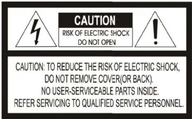
EXPLANATION OF GRAPHICAL SYMBOLS

The lightning flash with arrowhead symbol, within an equilateral triangle, is intended to alert the user to the presence of uninsulated "dangerous voltage" within the product's enclosure that may be of sufficient magnitude to constitute a risk of electric shock to persons.

The exclamation point within an equilateral triangle is intended to alert the user to the presence of important operating and maintenance (servicing) instruction in the literature accompanying the product.
TABLE OF CONTENTS
1 PRODUCT INTRODUCTION....3
1.1 PACKAGE CONTENTS .... 3
1.2 FUNCTION DESCRIPTION .... 3
2 INSTALLATION....4
2.1 INSTALLATION ....4
2.1.1 WALL MOUNTED 5
2.2.1 PTZ Connection 6
2.2.3 Setting IE Browser 6
2.2.4 Install Active X....7
2.3.1 Video Browse 8
2.3.2 PTZ Control....9
2.3.3 PTZ Function....9
2.3.4 Common Shortcuts....10
2.4 SETTING 10
2.4.1 System....11
2.4.2 Network....13
2.4.4 Camera 16
2.4.5 Video & Audio 19
2.4.6 PTZ Function....24
2.4.7 Alarm 25
2.4.8 User 25
2.4.9 log....26
3. FUNCTION INSTRUCTION....26
3.1 SPECIAL FUNCTION....26
4 OSD MENU 27
4.1 MENU INDEX 27
4.2 SYSTEM INFORMATION 28
4.3 DOME....28
4.3.1 Communication....29
4.3.2 IR Display 29
4.3.3 Guard Tours....30
4.3.4 A-B Scan 30
4.3.5 Pan Scan 31
4.3.6 Pattern 31
4.3.7 Park Action 31
4.3.8 Privacy Zone( Optional) 32
4.3.9 Advanced....33
4.4 CAMERA....33
4.5 DISPLAY 34
4.6 LANGUAGE 34
4.7 TIMING TASK....34
4.8 ALARM (OPTIONAL) 35
1 PRODUCT INTRODUCTION
1.1 PACKAGE CONTENTS
IP IR Speed dome 1pc
Wall mount bracket 1pc
Power supply 1pc
Screws kits 1pc
User manual 1pc
1.2 FUNCTION DESCRIPTION
3D Allocation
Allows the camera to move diagonally while using zoom function
Pattern
A series of pan, tilt, zoom and focus movements from a single programmable dome. Up to 4 patterns may be programmed for the dome camera.
Auto Flip
When the Speed Dome camera is mounted, it can track a moving target in a path directly below the camera. When the camera reaches the moving object directly below the dome, the dome will rotate to keep the image in the correct view
Focus
The auto focus enables the camera to focus automatically to maintain a clear image. Under the following conditions camera will not auto focus on the camera target:
(1) Target is not in the center of the screen;
(2) Attempting to view images that are far and near at the same time;
(3) Target is very bright object, such as neon lamp, etc;
(4) Targets are behind glass covered with water droplets or dust;
(5) Targets are moving quickly;
(6) Low contrast large area targets, such as walls;
(7) Targets are too dark or faint.
BLC (Back Light Compensation)
BLC(Back Light Compensation) is used to brighten an image in the foreground with a bright area behind it such as sunlight, limiting the affect of silhouette
Iris Control
Factory default is automatic camera aperture; in this mode the camera senses changes in ambient light and through moving and adjusting the lens aperture it makes the brightness of the output image stable.
Ratio Speed
Intelligent pan and tilt speed is variable depend on the zoom factor. When zooming in, the speed will become slower and when zooming out, the speed will become faster.
360 Scan
360° continuously scans the display scene at a set speed in a horizontal direction under the condition that pitch angle remains the same. In the scanning status, operator can move the joystick to exit from scanning.
Preset
A Position preset stores pan, tilt, zoom and focusing positions with predefined camera presets. Position presets can be call directly, assigned to actions or applied as "HOME" position.
Guard Tour Scan
Dome patrol scans according to certain edited preset order.
A-B Scan
The dome scans back and forth between two preset points (A & B).
Power Off Memory
This feature allows the dome to resume its previous status after power is restored.
Park Action
The Park function applies to the predefined functions such as Preset, Tour, Pattern, or Scan function after the dome has been idle for a programmed time.
2 INSTALLATION
2.1 INSTALLATION
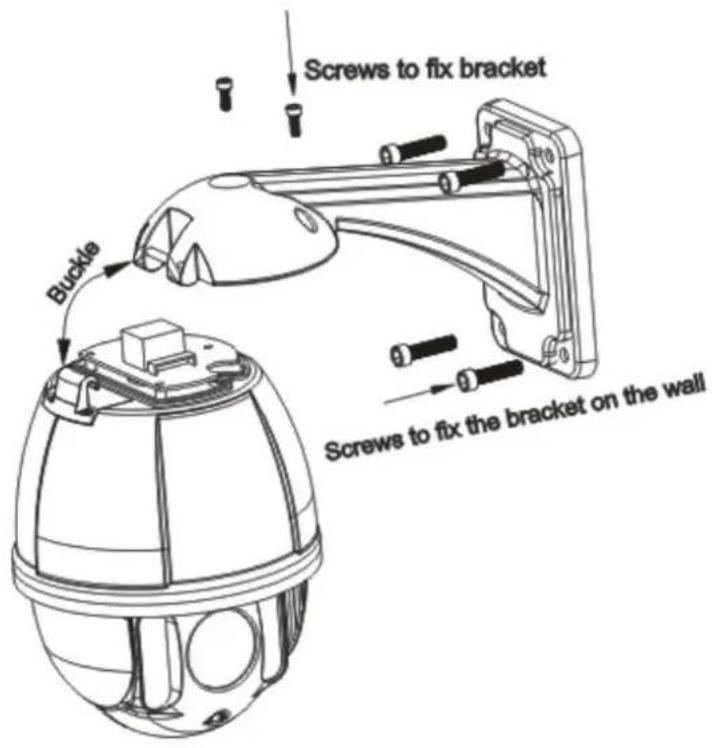
2.1.1 WALL MOUNTED
Installation conditions:
Wall mounted domes can be used in a hard wall structure whose thickness should be enough to install expansion bolts in an indoor and outdoor environment. The wall must bear at least 4 times the weight of the dome.
Installing the wall bracket:
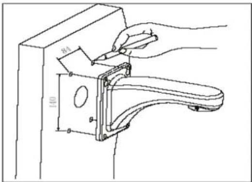
Fig 2.3
As shown in fig 2.4, fix the wall hanging bracket on the wall with wire and cable through it.
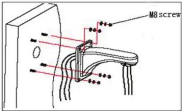
Fig 2.4
2.2.1 PTZ Connection
Before connecting, please power off and read the instructions carefully of all connected devices.
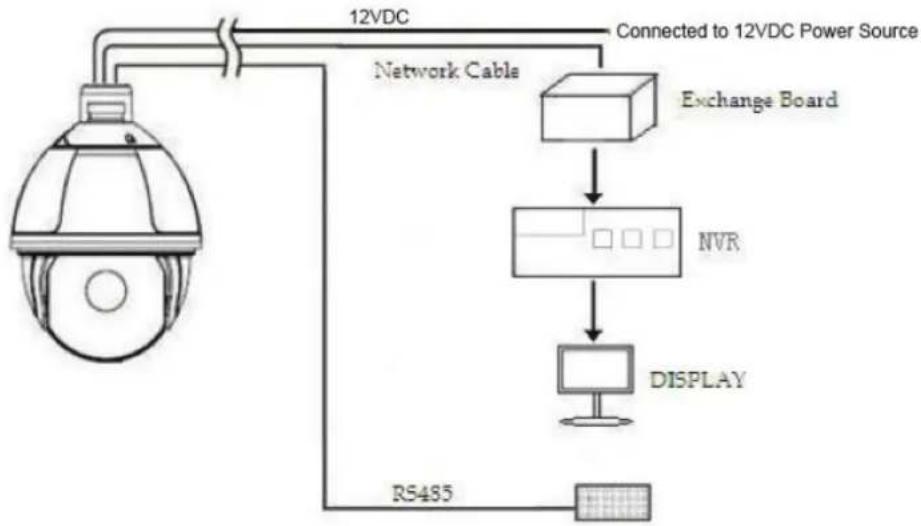
flowchart
graph TD
    A["12VDC"] --> B["Connected to 12VDC Power Source"]
    B --> C["Exchange Board"]
    C --> D["NVR"]
    D --> E["DISPLAY"]
    E --> F["RS485"]
    F --> A
    style A fill:#f9f,stroke:#333
    style B fill:#ccf,stroke:#333
    style C fill:#cfc,stroke:#333
    style D fill:#fcc,stroke:#333
    style E fill:#cff,stroke:#333
    style F fill:#ffc,stroke:#333
2.2.2 Connecting the Device
This device can be directly connected to a computer or network;
2.2.3 Setting IE Browser
User can view video through IE, ActiveX is required to be installed.
-
From menu, click "tool", then choose "Internet options".
-
Then click "Security":
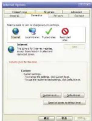
Fig 2.13
- Choose internet icon, click "Customs level". Then the follow pops up:
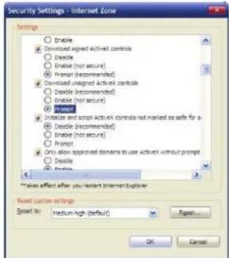
Fig 2.14
- Change option "Download unsigned ActiveX controls" to "Enable" or "Prompt". User can optionally change "Running ActiveX controls and plug-in" into "Start" to avoid the prompt of running.
2.2.4 Install Active X
(1) Download controls
Open IE and enter IP cameras IP address (default is 192.168.1.110).
On home page of camera login using user name and password (default is admin & admin)
(2) Install and run controls:
Please click "Run" in the prompt box.
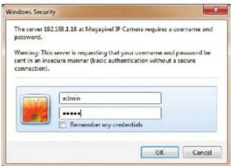
If it is the first time you are running the software, please login as a super user.
After login, you will enter the following interface:
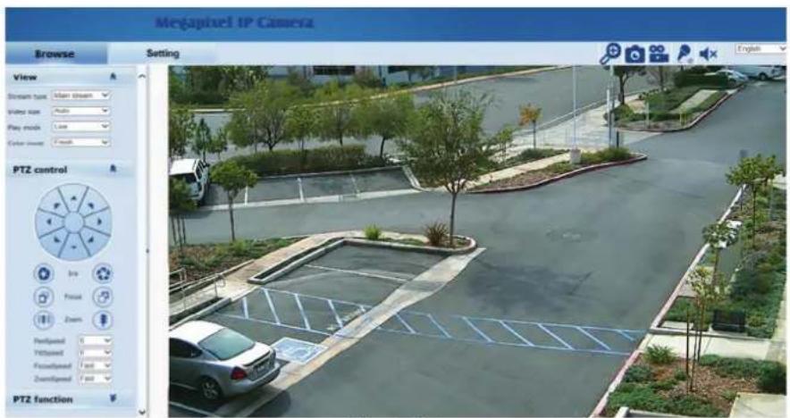
Fig 2.16
The IP Camera supports H.265/H.265 and MJPEG triple encoding format.
2.3.1 Video Browse
Video Browse: For camera display setting, you can set the video type, video size, play mode, image color. On the browsing interface, click "video" to enter system setting interface. Here is the picture:
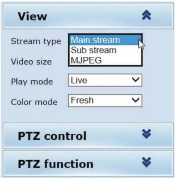
Fig 2.18
Set the video in the menu above:
Video Type: H.264/265 main stream, H.264 sub stream, MJPEG.
Video Size: screen original size 1*, original size *1/2, adaptive.
Play mode: Live, smooth.
Image Color: Fresh, Standard, Cold
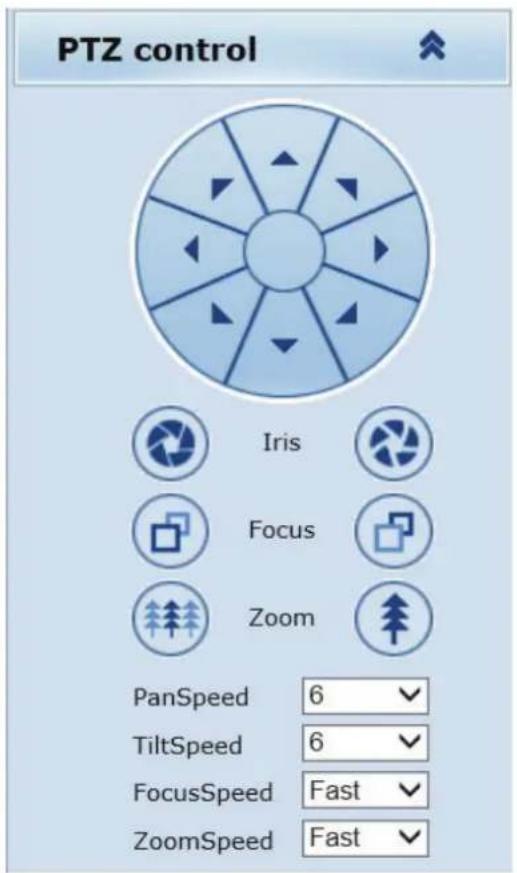
2.3.2 PTZ Control
PTZ control: Adjust the rotation in all directions, set pan speed, tilt speed.
2.3.3 PTZ Function
PTZ functions: preset, auto pan, pattern, tour.
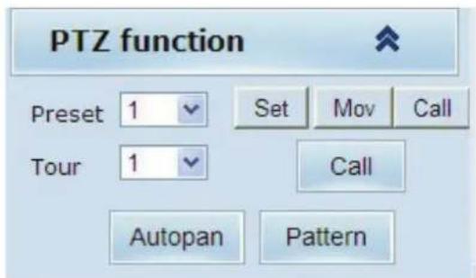
Fig 2.30
2.3.4 Common Shortcuts
Common shortcuts: Digital Zoom, Snapshot, record, audio input (not used), audio output (not used), English- Chinese

Fig 2.21
Frequently set common functions of the IP camera. The storage path of snapshot and recording complies with the one from settings.
The snapshots are stored in the name of IP address and time of the device. For example, the file name is 20140520_221325_125_01_192.168.1.110.jpg, which means the device's IP address is 192.168.1.110 and snapshot's time is at 22:13:25:125 on May 20^th 2014.
2.4 SETTING
Setting: detailed setting of system, network, IPC, audio & video, PTZ functions, alarm, user, log.
| Megapixel IP Camera | ||||
| Browse | Setting | |||
| System | System Time Advanced | |||
| Basic information | ||||
| Network | Version: V1.04.10-160812 Time zone: GMT-07:00 | |||
| Camera | Product info: IPD-D41C02-BS series SerialNum: 1B4B511C030A | |||
| Video&Audio | Network settings | |||
| PTZ Function | MAC address: 1C-7C-45-11-00-07 IP address: 192.168.1.210 | |||
| Default gateway: 192.168.1.1 Subnet mask: 255.255.255.0 | ||||
| Alarm | Alarm settings | |||
| Record | Alarm server 1 IP: 0.0.0.0 | |||
| Alarm server 2 IP: 0.0.0.0 | ||||
| Manage Users | Alarm server 3 IP: 0.0.0.0 | |||
| Log | NTP settings | |||
| NTP server : 192.168.1.100 | ||||
| video settings | ||||
| □ Public video parameters: | ||||
| Brightness: 128 Contrast: 128 Saturation: 128 Sharpness: 128 | ||||
| □ Main stream parameters: | ||||
| Resolution: 2592x1520 Frame rate: 25 Bit rate: VBR(upper limit: 6144Kbps) I/P rate: 50 | ||||
| □ Sub stream parameters: | ||||
| Resolution: 640x480 Frame rate: 25 Bit rate: VBR(upper limit: 1024Kbps) I/P rate: 50 | ||||
| MJPEG video settings | ||||
2.4.1 System
System: upgrade the system info, time and maintenance.
System info: The initial interface of system setting is the display interface of system info.
Basic Info: The IPC's version number, time zone, product series, serial number.
Network Settings: MAC address, IP address, default gateway, subnet mask.
Alarm setting: Alarm server IP, alarm correlation (not used).
NTP setting: NTP server IP.
Video setting: main stream/sub stream resolution, frame rate, bit rate, I/P rate.
MJPEG videosetting: resolution, frame rate.
Time: time zone setting, NTP setting, real-time synchronization parameter setting.
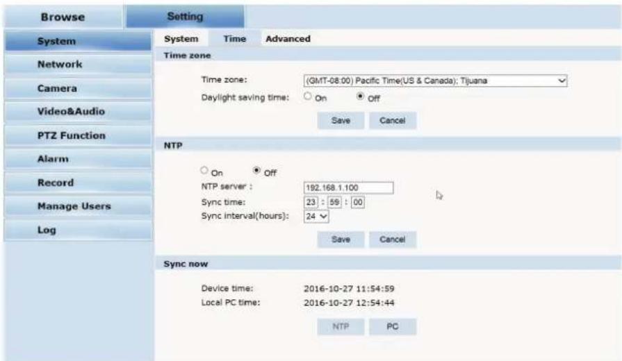
Fig 2.24
Time zone setting: select your time zone from the drop down list, click "Save"
NTP Synchronization: whether to start NTP service. Select to start NTP service,
If NTP service starts, input NTP server address in the IP field, and click
"Save" button. After NTP is activated, the system corrects the time with NTP automatically.
Local synchronization: set camera time to synchronize with local PC.
Advanced: contains upgrading the device's software, restoring factory settings and restarting the system.
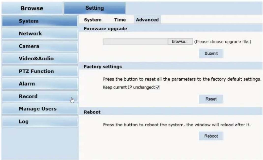
Fig 2.25
Firmware upgrade: To upgrade the firmware of the camera click on Browse to locate the upgrade file, after locating the file click on "Submit" and camera will start upgrading
Please restart the device after upgrading.
Restore factory setting: Click "Reset to reset camera to factory default. Check "Keep current IP unchanged" to protect the cameras IP address
Reboot: click "Reboot" button to restart the camera, this will take about 90 seconds.
2.4.2 Network
Network: The device's relevant network parameter setting, including Network、FTP、SMTP、QoS、IGMP、PORT、DDNS、Cloudlens
Network: setting of the device's network parameter.
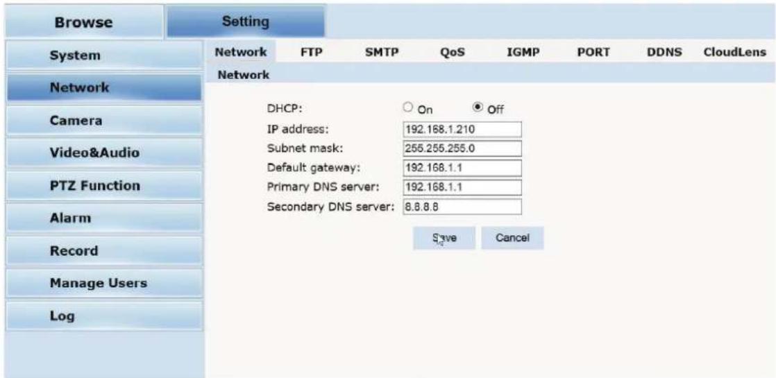
Fig 2.27
DHCP: Dynamic Host Configuration Protocol, allocating dynamic IP
address for network clients. Select "on", the camera's IP address and the subnet mask cannot be modified, but automatically allocated by the host. Select "off" to manually set IP address
FTP: FTP (File Transfer Protocol) is application layer protocol, based on transport layer for client's service. FTP is in charge of transferring files. The IP camera supports FTP photo uploading function on alarm. On FTP interface, set the server address, username and password, activate FTP alarm at alarm setting.
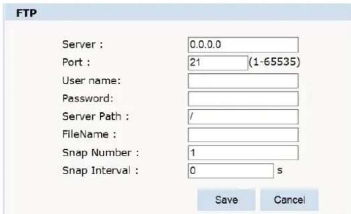
Fig 2.28
SMTP: Simple Mail Transfer Protocol is a TCP/IP protocol used in sending and receiving e-mails
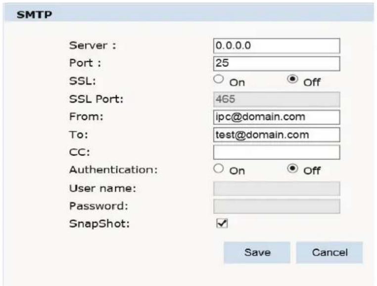
Fig 2.29
- Server IP: set up mail server IP.
- Port: set SMTP port
- SSL: on or off
- SSL Port: which port for SSL
- From: set up the email address of the sender.
• To: the recipient email address
• CC: copy to different email address - Authentication: Turn on or off the authentication function via mail server verification.
- User name: Sender's name. User can set by itself.
- Password: Set sender's password.
- Snapshot: to attach a snapshot to the email
Note: No restrictions for setting username and password.
After setting, please click "Save".
If the user selects "mail" at "Alarm Setting", the system would send emails according to the
QoS: Quality of Service, a kind of network secure mechanism, a technology of solving network delay and congestion.
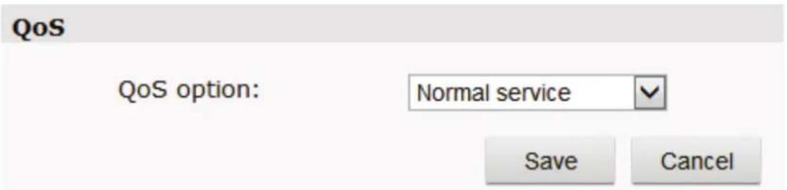
Fig 2.32
IGMP: The Internet Group Management Protocol (IGMP) is a communications protocol used by hosts and adjacent routers on IPv4 networks to establish multicast group memberships. IGMP is an integral part of IP multicast.
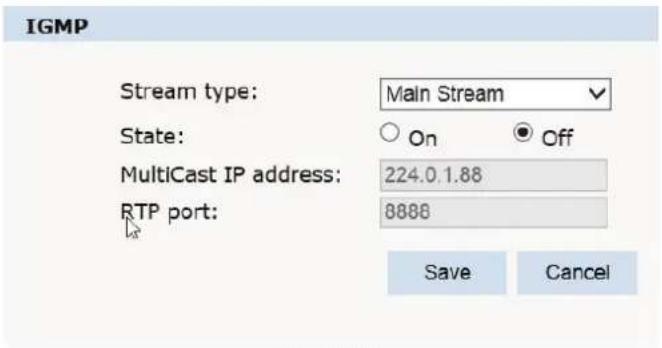
Fig 2.33
PORT: an interface, passing data between the computer and other devices (e.g. Printer, mouse, keyboard, monitors), among network, or other computers in connection.
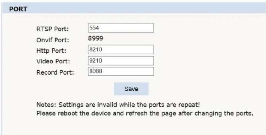
Fig 2.34
DDNS: DDNS: When enabled the HYBRID-DVR can be accessed through a dynamic DNS server.
Commonly used if a broadband connection does not have a static IP address.
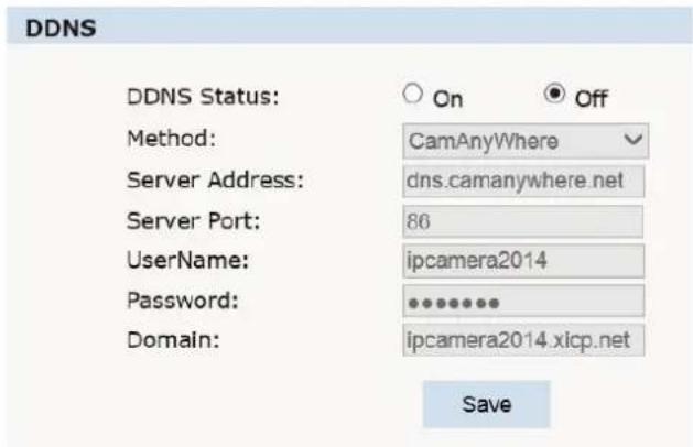
Fig 2.35
2.4.4 Camera
Basic settings, Exposure settings, Effect settings, White Balance and Reset.
Basic Settings:
On and off setting of camera system, noise, mirror, BLC and other function.
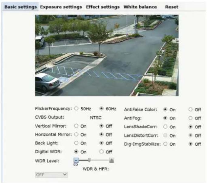
Fig 2.38
Power Frequency: 60Hz = NTSC 50Hz = PAL
Vertical Mirror: image vertical mirror display.
Horizon Mirror: image horizontal mirror display.
BLC: BLC offers ideal exposure in front of strong backlight..
Digital WDR: improves image when object is both in bright and dark areas
Anti False color: helps improve color reproduction
Anti Fog: improves visibility in foggy conditions
Lens Shade Correction: when lens is zoomed out all the way edges might appear darker, this will brighten up these edges.
Dig-Img Stabilizer: will reduce minor vibrations
Exposure Settings:
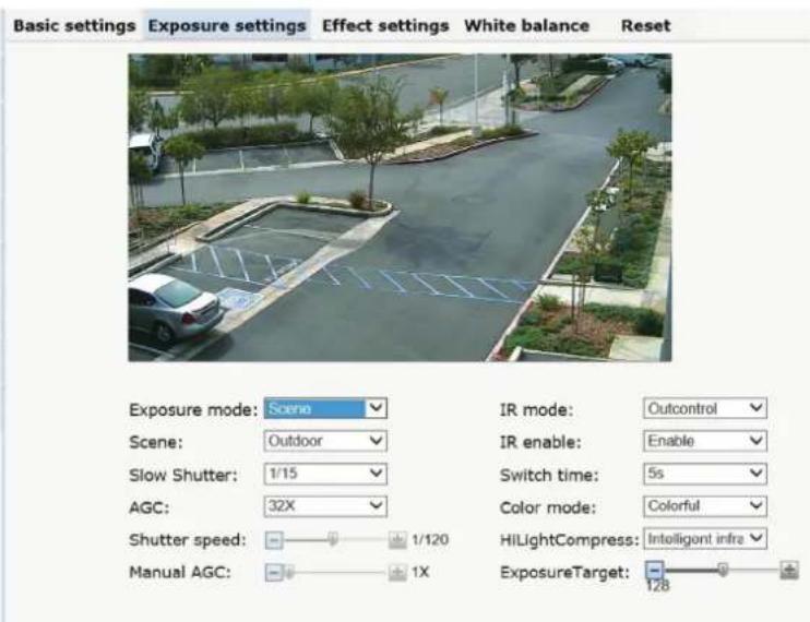
Fig 2.39
Exposure Mode: select which mode is best suited for applications
Scene Select: Indoor, optimized for indoor applications, Outdoor, optimized for outdoor applications
Slow Shutter: in low light applications shutter will slow to selected settings for best image
AGC: Automatic Gain Control, adjusts the Gain up to the level selected to optimize the image
Shutter Speed: when Exposure Mode is in Shutter or Manual you can adjust the Shutter speed
Manual AGC: when Exposure Mode is in Manual you can adjust both the Shutter speed and the AGC
IR Mode: Out Control (External sensor turns on IR's) Night (camera is in B/W mode all the time) Day (camera is in color all the time) Auto (for cameras that do not have IR's)
IR Enable: Turns IR's on or off
Switch Time: delay before turning from color to b/w or from b/w to color
Color Mode: adjust the overall hue
Hi Light Compress: how the IR's react to objects
Exposure Target: how intense the IR's will react
Effect Settings:
General/Mode: select General for basic adjustments and Mode for custom adjustments
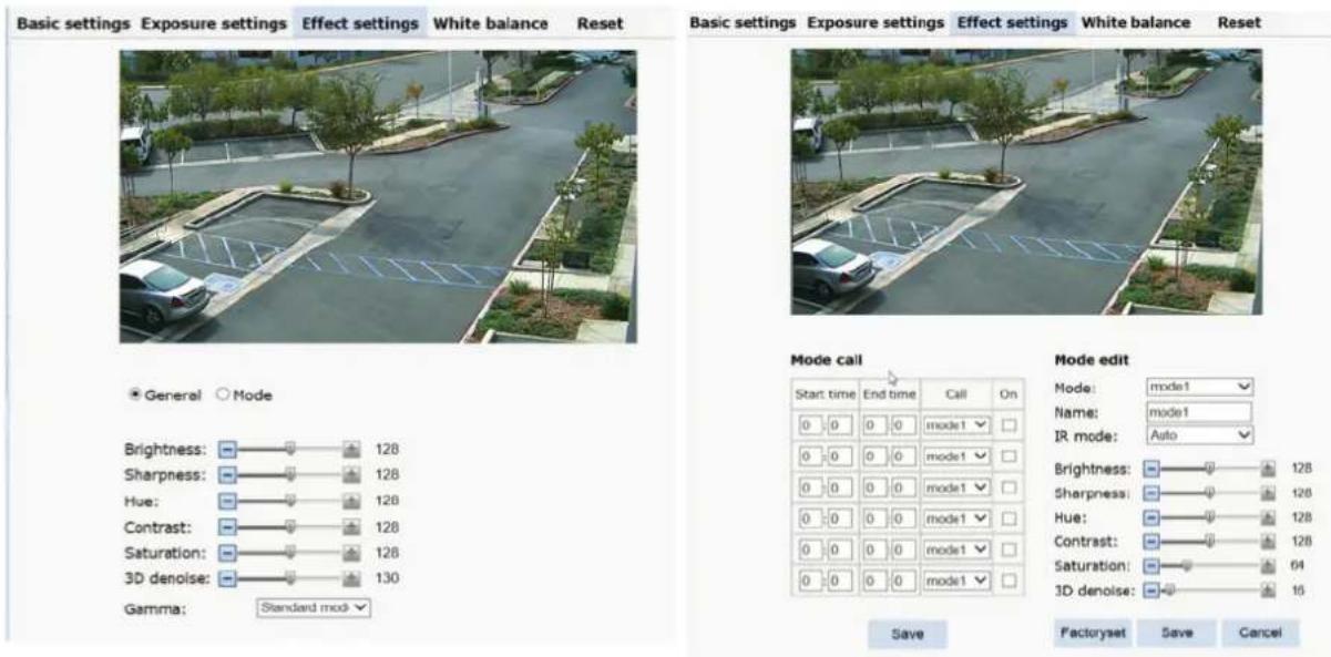
Fig 2.40
White Balance: Auto, Manual, Sunlight, Cloudy, Incandescent, Cool White/Fluorescent, Sodium.
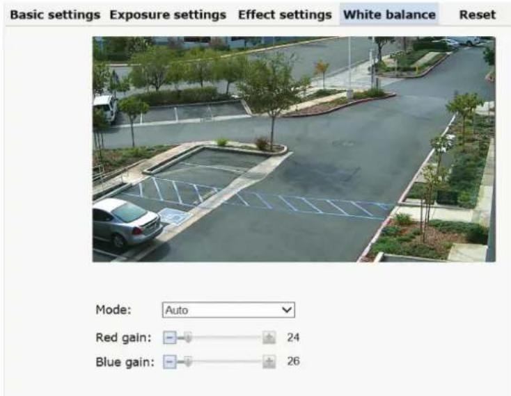
Fig 2.41
Reset: Click "Reset" to return to factory default.
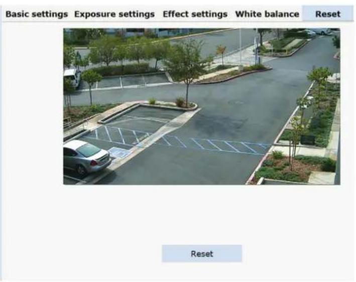
2.4.5 Video & Audio
Video:
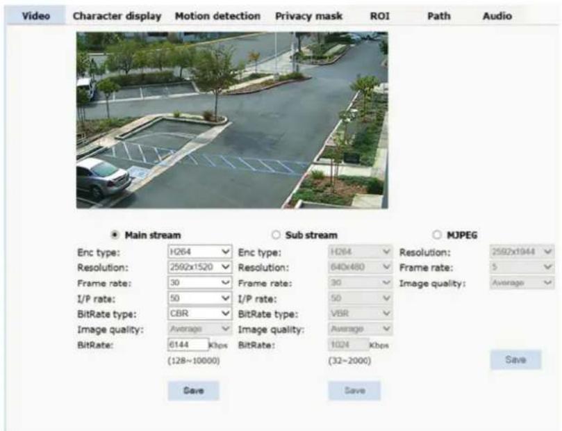
Fig 2.43
Stream Type: Main Stream, Sub Stream, MJPEG.
Resolution Main: 2592 x 1520, 2304 x 1296, 1920 x 1080, 1280 x 960, 1280 x 720.
Resolution Sub Stream: 640 x 480, 480 x 360, 352 x 288, 320 x 240, 176 x 144, closed
Resolution MJPEG: 2592 x 1944, 2592 x 1520, 2048 x 1536, 1920 x 1080, 1280 x 720, closed
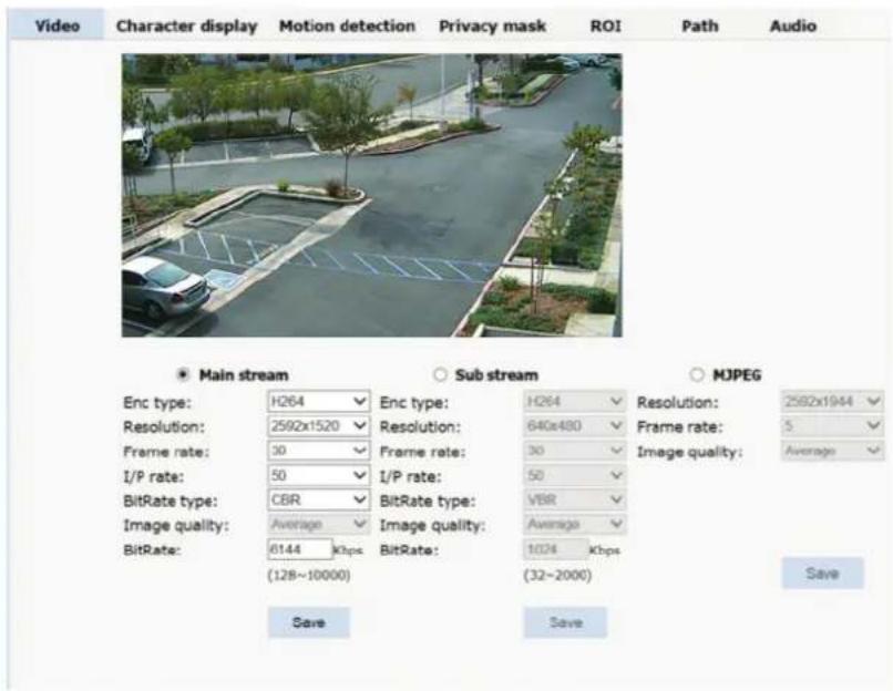
Enc Type: Encoding H.264/ H.265
Resolution: select resolution per stream
Frame Rate: select frame rate per stream
I/P: I/P frames interval
Bit Rate Type: select between CBR (constant bit rate) or VBR (variable bit rate)
Image Quality: when in VBR Bit Rate type choose between Lowest, low, Average, High, Highest
Bit Rate: when in CBR (constant bit rate) set bit rate to use
Character Display: Text, time, date can be displayed on the screen. X/Y (0-99) dimension stands for position.
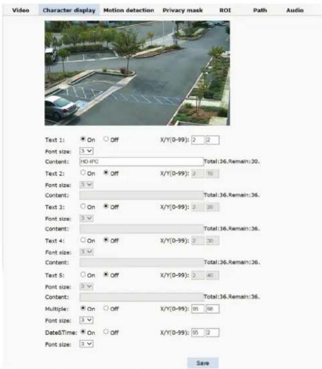
Fig 2.44
OSD setting includes: Text OSD, Zoom OSD and Date and Time OSD.
Text 1\~5 OSD: Set the subject and position. Choose On or Off to display the text or not.
Input the content up to 36 characters can be displayed. X and Y
coordinate is based on the zero coordinate on the upper left corner of the image. X and Y
coordinate can be set to any number between 0 to 99.
After setting the text content and coordinate, click display. Then the
text will appear on the video. If you want to cancel it, choose off then click SAVE
Multiple: will display the zoom ratio
Date & Time OSD: set date & Time, position, ON or OFF.
Motion Detection:
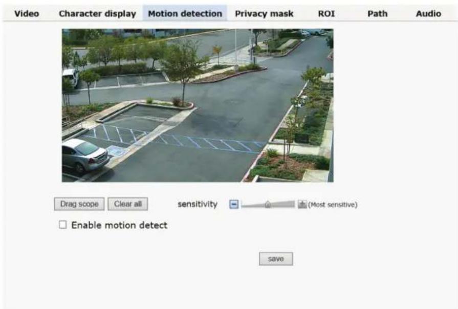
Fig 2.45
Drag Scope: Click on Drag Scope then click and drag on image where motion grid is to be located.
Clear All: will remove motion grid
Sensitivity: adjust the sensitivity.
Enable Motion Detect: Turns on and off the motion detection
Privacy Zone: setting the privacy zone of the camera. This zone can not move. It is available if PTZ is in a fixed place.
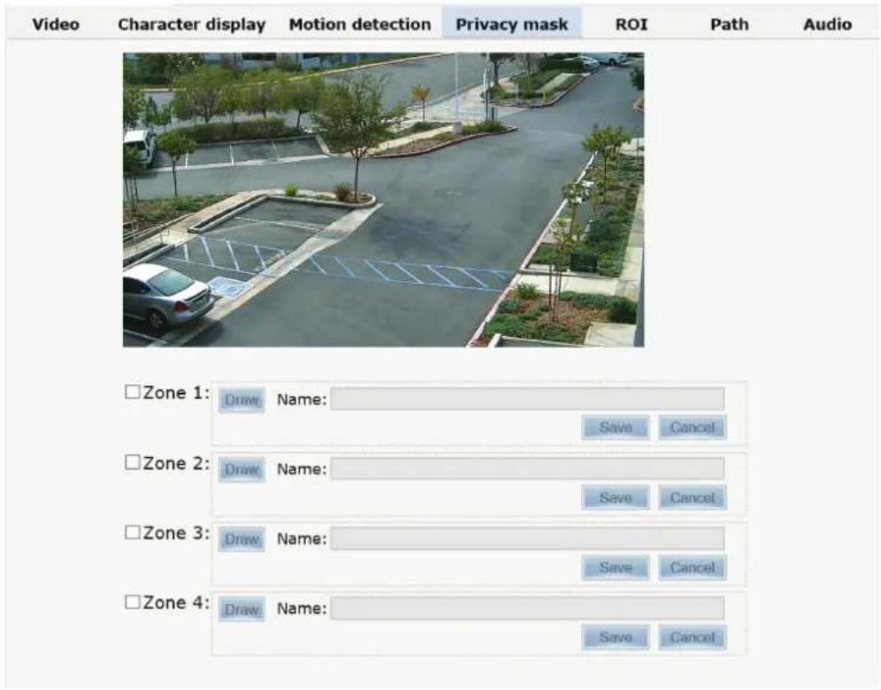
【Zone】: You can set 4 privacy zones. Each of them can be drawn and set with a mouse. Select save and the zone is covered.
ROI: Future use
Path: storage path of IE recording and snapshot.
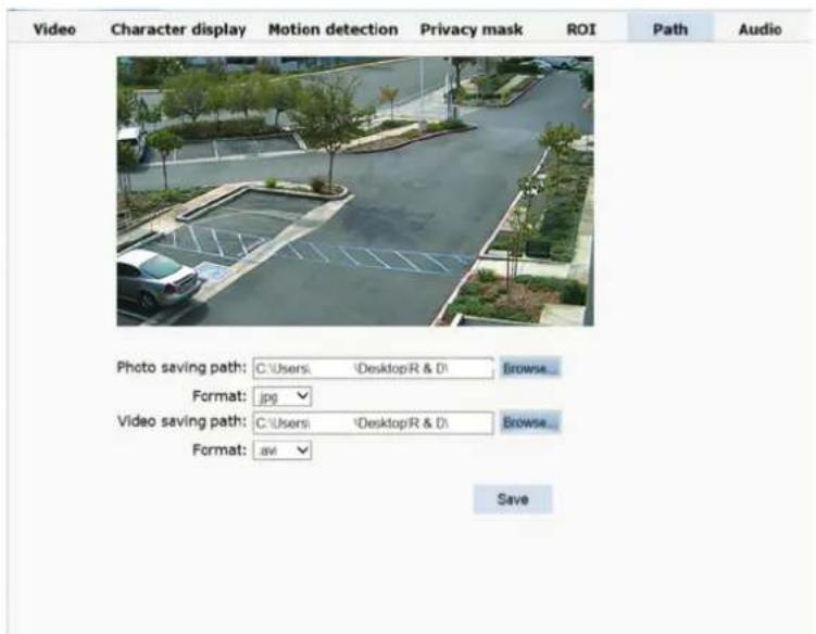
Fig 2.47
The default is C drive control folder. Click browse to re-select the storage path. For the type of the file, photos is jpg/bmp and video is avi/ifv.
Audio: Future use
2.4.6 PTZ Function
PTZ function: preset, Auto tour, PTZ protocol.
Preset: Set where you want the camera to point at when you call up preset.
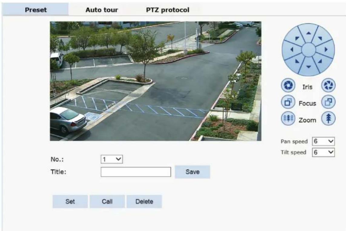
Fig 2.48
Auto Tour:
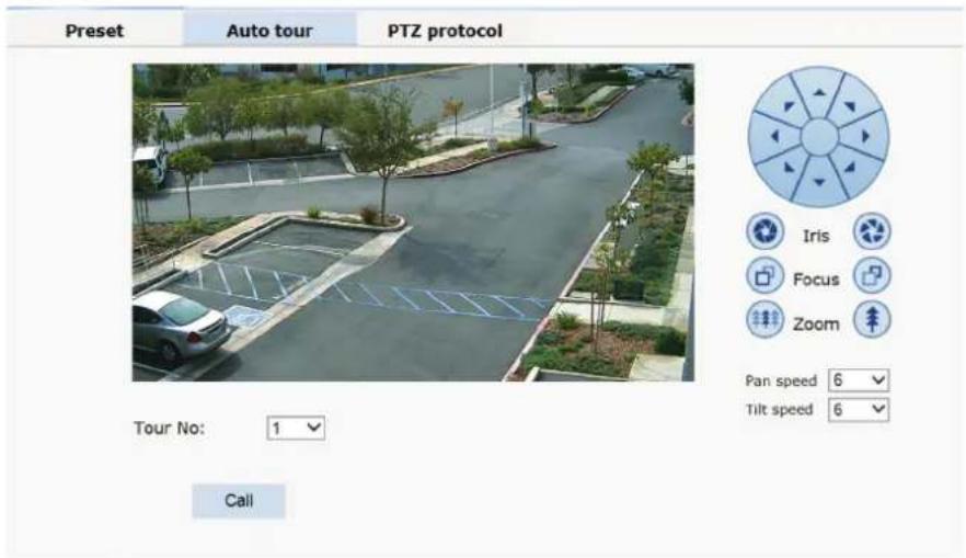
Fig 2.52
Please set Auto Tour in OSD menu (preset 95)
2.4.7 Alarm
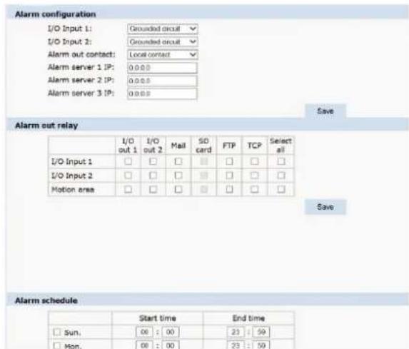
Not available, for future use
Record: Not available, for future use
2.4.8 User
User: Administrator's authority to operate the camera.
| Add user | |||
| Num | User name | Property | Operation |
| 1 | admin | ||
Fig 2.54
Add user: click the image " Add user ", you will get the following dialog box
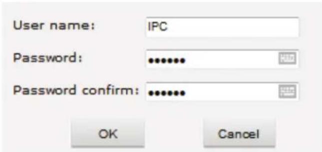
Fig 2.55
Input user name and password.
| Add user | |||
| Num | User name | Property | Operation |
| 1 | admin | ||
| 2 | IPC | ||
Fig 2.56
2.4.9 log
Log: recording of each operation
| Browse | Setting | |||
| System | Date | Time | Log | |
| Network | 2016 - 11 - 03 | 15 : 13 : 38 | app: Get a motion alarm. | |
| 2016 - 11 - 03 | 15 : 13 : 33 | app: Get a motion alarm. | ||
| Camera | 2016 - 11 - 03 | 14 : 41 : 18 | app: Get a motion alarm. | |
| 2016 - 11 - 03 | 14 : 29 : 19 | app: Get a motion alarm. | ||
| Video&Audio | 2016 - 11 - 03 | 14 : 29 : 03 | last message repeated 2 times | |
| 2016 - 11 - 03 | 14 : 28 : 11 | last message repeated 6 times | ||
| 2016 - 11 - 03 | 14 : 26 : 33 | last message repeated 3 times | ||
| PTZ Function | 2016 - 11 - 03 | 14 : 25 : 58 | last message repeated 2 times | |
| 2016 - 11 - 03 | 14 : 25 : 03 | last message repeated 9 times | ||
| Alarm | 2016 - 11 - 03 | 14 : 24 : 10 | app: Get a motion alarm. | |
| Record | 2016 - 11 - 03 | 14 : 23 : 10 | app: Get a motion alarm. | |
| Manage Users | 2016 - 11 - 03 | 14 : 20 : 21 | last message repeated 2 times | |
| 2016 - 11 - 03 | 14 : 19 : 15 | app: Get a motion alarm. | ||
| Log | 2016 - 11 - 03 | 14 : 19 : 11 | app: Get a motion alarm. | |
Fig 2.57
3. FUNCTION INSTRUCTION
The follow presets are predefined as special function
| PREST | FUNCTION | PRESET | FUNCTION |
| 34 Reset | 84 Turn on far light | ||
| 35 Run Wiper | 85 Turn on near light | ||
| 36 Stop Wiper | 91(31) Call A-B scan | ||
| 75 | Pattern 1 | 1 Set left point of A-B scan | |
| 76 Pattern | 2 2 Set right point of A-B scan | ||
| 77 | Pattern 3 | 96 | Guard tour 3 |
| 78 | Pattern 4 | 97 | Guard tour 2 |
| 81(41) | Auto Day/Night | 98(38) | Guard tour 1 |
| 82(42) | Night Mode | 99 | Pan scan |
| 83 | Day Mode |
4 OSD MENU
Select Preset 95 to enter OSD menu of PTZ.
4.1 MENU INDEX
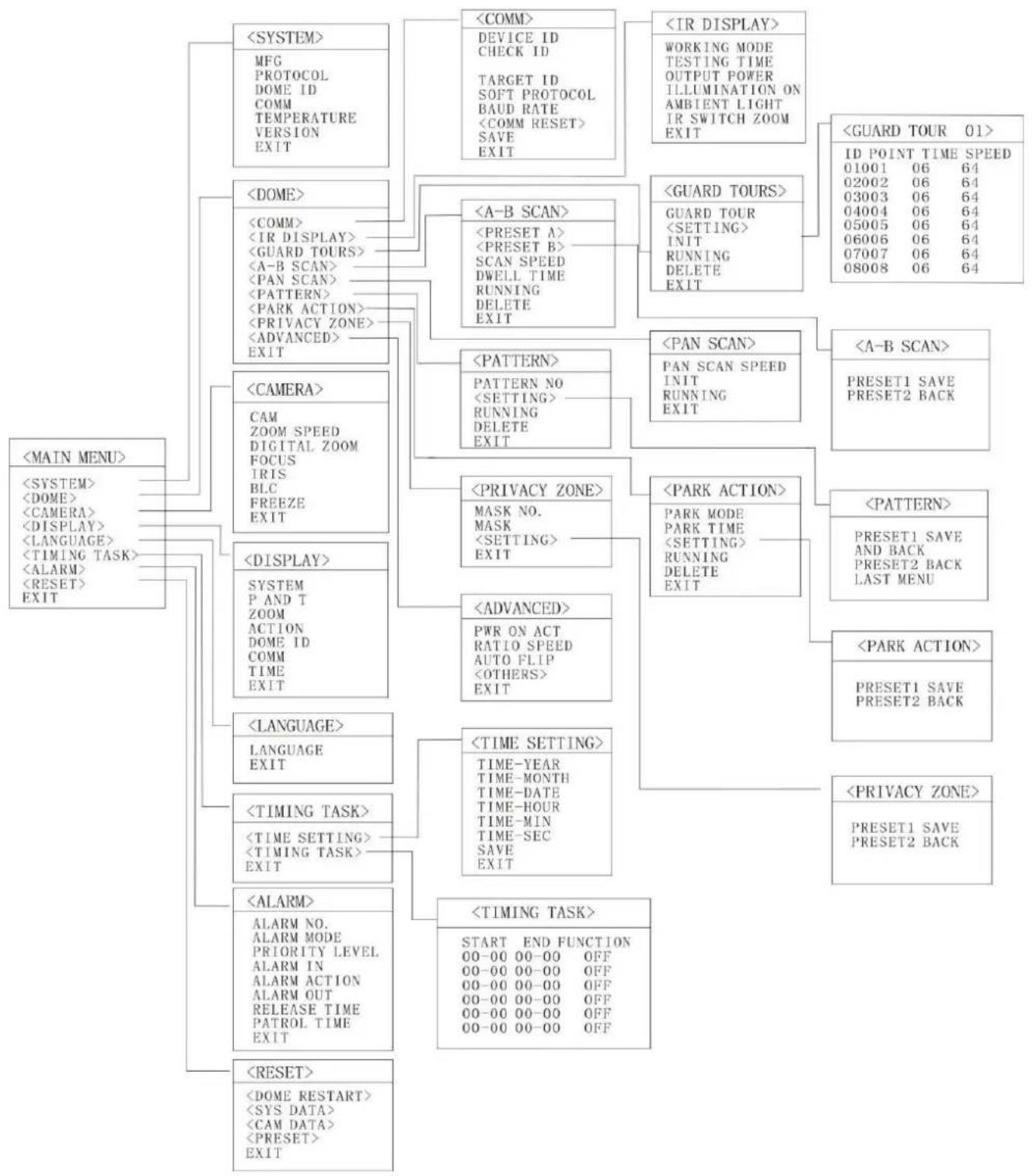
flowchart
graph TD
    A["<<MAIN MENU>>"] --> B["<<SYSTEM>>"]
    A --> C["<<DOME>>"]
    A --> D["<<CAMERA>>"]
    A --> E["<<DISPLAY>>"]
    A --> F["<<LANGUAGE>>"]
    A --> G["<<TIMING TASK>>"]
    A --> H["<<ALARM>>"]
    A --> I["<<RESET>>"]

    B --> J["<<SYSTEM>>"]
    B --> K["<<COMM>>"]
    B --> L["<<IR DISPLAY>>"]
    B --> M["<<GUARD TOURS>>"]
    B --> N["<<A-B SCAN>>"]
    B --> O["<<PAN SCAN>>"]
    B --> P["<<PATTERN>>"]
    B --> Q["<<PARK ACTION>>"]

    C --> R["<<SYSTEM>>"]
    C --> S["<<CAMERA>>"]
    C --> T["<<DISPLAY>>"]
    C --> U["<<LANGUAGE>>"]
    C --> V["<<TIMING TASK>>"]
    C --> W["<<ALARM>>"]
    C --> X["<<RESET>>"]

    D --> Y["<<SYSTEM>>"]
    D --> Z["<<COMM>>"]
    D --> AA["<<IR DISPLAY>>"]
    D --> AB["<<GUARD TOURS>>"]
    D --> AC["<<A-B SCAN>>"]

    E --> AD["<<SYSTEM>>"]
    E --> AE["<<CAMERA>>"]
    E --> AF["<<DISPLAY>>"]
    E --> AG["<<LANGUAGE>>"]
    E --> AH["<<TIMING TASK>>"]
    E --> AI["<<ALARM>>"]
    E --> AJ["<<RESET>>"]

    F --> AK["<<SYSTEM>>"]
    F --> AL["<<COMM>>"]
    F --> AM["<<IR DISPLAY>>"]
    F --> AN["<<GUARD TOURS>>"]
    F --> AO["<<A-B SCAN>>"]

    G --> AP["<<SYSTEM>>"]
    G --> AQ["<<CAMERA>>"]
    G --> AR["<<DISPLAY>>"]
    G --> AS["<<LANGUAGE>>"]
    G --> AT["<<TIMING TASK>>"]
    G --> AU["<<ALARM>>"]
    G --> AV["<<RESET>>"]

    H --> AW["<<SYSTEM>>"]
    H --> AX["<<COMM>>"]
    H --> AY["<<IR DISPLAY>>"]
    H --> AZ["<<GUARD TOURS>>"]
    H --> BA["<<A-B SCAN>>"]

    I --> BB["<<SYSTEM>>"]

    J --> BC["<<COMM>>"]
    J --> BD["<<PARAMETER ID >"]

    K --> BE["<<COMM>>"]
    K --> BF["<<PARAMETER ID >"]

    L --> BG["<<COMM>>"]
    L --> BH["<<PARAMETER ID >"]

    M --> BI["<<PARAMETER ID >"]

    N --> BJ["<<PARAMETER ID >"]

    O --> BK["<<PARAMETER ID >"]

    P --> BL["<<PARAMETER ID >"]

    Q --> BM["<<PARAMETER ID >"]

    R --> BN["<<PARAMETER ID >"]

    S --> BO["<<PARAMETER ID >"]

    T --> BP["<<PARAMETER ID >"]

    U --> BQ["<<PARAMETER ID >"]

    V --> BR["<<PARAMETER ID >"]

    W --> BS["<<PARAMETER ID >"]

    X --> BT["<<PARAMETER ID >"]
4.2 SYSTEM INFORMATION
| MFG | |
| PROTOCOL PELCO D-P | |
| DOME ID 001 | |
| COMM 2400.N.8.1 | |
| TEMPERATURE 41.8°C | |
| VERSION V863R15122109 | |
| EXIT |
When enter the OSD, it display Enter to the SYSTEM, you will see:
MFG: Max 15 characters displayed on the
screen. PROTOCOL: Display the protocol of the
dome DOME ID: Display the dome address
COMM: Baud rate.
TEMPERATURE: Display the temperature of the camera, it changes along with the temperature of the camera, the data is unchangeable by manual.
VERSION: Version will update along with the product upgrading
Remark: Protocol, ID and COMM all can be set in menu
4.3 DOME
| <DOME> |
| <COMM> |
| <IR DISPLAY> |
| <GUARD TOURS> |
| <A-B SCAN> |
| <PAN SCAN> |
| <PATTERN> |
| <PARK ACTION > |
| <PRIVACY ZONE> |
| <ADVANCED> |
| EXIT |
4.3.1 Communication
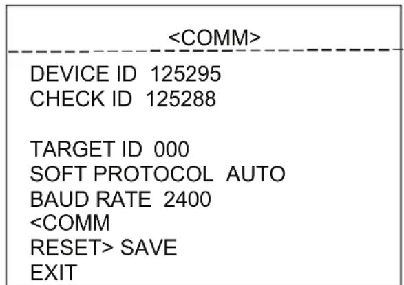
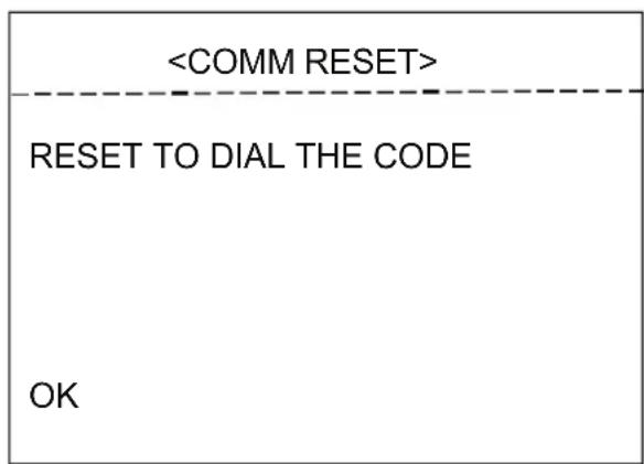
DEVICE ID: It is only and used to distinct from the ID of other domes.
CHECK ID: Distinguish several domes with same ID. And altering target ID, soft protocol and baud rate needs to enter check ID in line with the device ID, otherwise altering can't be completed.
TARGET ID: Target ID is available from 001 to 250.
SOFT PROTOCOL: Soft protocol is auto, Pelco-D and Pelco-P available
BAUD RATE: 1200BPS, 2400BPS, 4800BPS, 9600BPS available
SAVE: Please save the change of communication. After saving, the dome will reboot.
4.3.2 IR Display
| <IR DISPLAY> | |
| WORKING MODE AUTO | |
| TESTING TIME | 08S |
| OUTPUT POWER | 100% |
| ILLUMINATION ON | 03 |
| AMBIENT LIGHT 09 | |
| IR SWITCH ZOOM | 06 |
| EXIT | |
WORKING MODE: Working mode has auto, black/white, color selectable. Default is auto.
TESTING TIME: On IR auto working mode and the programmed time, the IR will execute the programmed action, eg. Switch from day to night or from night to day. The detection time is from 2s to 15s selectable.
OUTPUT POWER: Output power has 40%, 60%, 80%, 100% for selection!
ILLUMINATION ON: Illumination on is 1 to 15 grade selectable and default is 3. On the auto IR working mode, if the illumination on level is less than the ambient light, the picture will change to color, the IR illumination will turn off automatically. If the illumination on level is
more than the ambient light, the picture will change to black, the IR illumination will turn on automatically.
AMBIENT LIGHT: Ambient light is a system data. User can not change it manually. It changes according to the environment all the time. The data will refresh every time when user enter the OSD. It is from 0 to 50 grade.
IR SWITCH ZOOM: When zoom value reaches to the demanded setting, the IR LEDs with auto switch from near illumination to far illumination, zoom value option from 01-23.
4.3.3 Guard Tours
| GUARD TOUR | 01 |
| INIT | |
| RUNNING | |
| DELETE | |
| EXIT | |
| ID | POINT | TIME(S) | SPEED |
| 1 | 01 | 06 | 64 |
| 2 | 02 | 06 | 64 |
| 3 | 03 | 06 | 64 |
| 4 | 04 | 06 | 64 |
| 5 | 05 | 06 | 64 |
| 6 | 06 | 06 | 64 |
| 7 | 07 | 06 | 64 |
| 8 | 08 | 06 | 64 |
GUARD TOUR: Total 3 guard tours selectable: 01, 02, 03.
SETTING: Each guard tour includes max 16 presets. The number of the preset is from 0-64, but 0 is not valid. Dwell time is 1 to 60s selectable. Speed is 1 to 64 grade selectable.
INIT: After init., preset point, dwell time, speed will resume to default setting.
RUNNING: Running the present guard tour.
DELETE: Delete the guard tour set. After deleting, the present preset points in the guard tours all display as 0. While the exact preset point information doesn't be deleted. So it is convenient for user to select the preset point needing to be guarded tour.
4.3.4 A-B Scan
| <A-B SCAN> | |
| PRESET A | 01 |
| PRESET B | 02 |
| SCAN SPEED | 20 |
| DWELL TIME | 06S |
| RUNNING | |
| DELETE | |
| EXIT | |
| A-B SCAN |
| RUNNING.... |
| PRESET 1:SAVE |
| PRESET 2:BACK |
PRESET A: On A-B scan, A point can be preset from 0 to 64
PRESET B: On A-B scan, B point can be preset from 0 to 64.
SCAN SPEED: A-B scan speed is 1 to 64 grade selectable.
DWELL TIME: Dwell time between A to B is 2s to 60s selectable.
RUNNING: Running the A-B scan. Check Fig. 4.3.4.2.
DELETE: After deleted, the preset points of A and B display as 0. While the exact preset point information doesn't be deleted. So it is convenient for user to select the preset point needing to be scanned. Speed and dwell time will reset as default setting
4.3.5 Pan Scan
| <PAN SCAN> | |
| PAN SCAN SPEED | 20 |
| INIT | |
| RUNNING | |
| EXIT | |
| PAN SCAN |
| RUNNING... |
PAN SCAN SPEED: Pan scan speed is 1 to 64 grade selectable.
INIT: Reset the scan speed and tilt degree as default setting.
RUNNING: Running the scan speed and tilt degree set.
4.3.6 Pattern
| <PATTERN> |
| PATTERN NO OFF |
| <SETTING> |
| RUNNING |
| DELETE |
| EXIT |
| <PATTERN> |
| PRESET 1 SAVE AND BACK |
| PRESET 2 BACK LAST MENU |
4.3.7 Park Action
| <PARK ACTION> |
| PARK MODE OFF |
| PARK TIME 01M |
| <SETTING> |
| CALL |
| DELETE |
| EXIT |
| <PARK ACTION> |
| PRESET 1: SAVEPRESET 2: BACK |
4.3.7.1 4.3.7.2
PARK MODE: Park mode includes OFF, Park action, A-B scan, Pan scan, guard tour 01, guard tour 02, guard tour 03 and Preserve action.
When park mode is OFF status, the dome doesn't run park mode.
When park mode is PRESERVE ACTION status, it records previous action order(A-B scan, Pan scan, Guard tour 01, Guard tour 02, Guard tour 03).
Example: Running A-B scan at first, when the action stops unexpectedly, it enters the park mode to continue to run A-B scan.
PARK TIME: Park time is 01\~60 Min's selectable.
SETTING: After entering the OSD menu, as 4.3.7.2, move to the desired position and save the settings.
CALL: Call the park action, if there is no setting, system will remind that "Please set park action".
DELETE: Delete the settings.
4.3.8 Privacy Zone(Optional)
| <PRIVACY ZONE> |
| MASK NO. 01MASK OFF |
| <SETTING> |
| EXIT |
| <PRIVACY ZONE> |
| PRESET1:SAVE AND BACKPRESET2:BACK LAST MENU |
| <PRIVACY ZONE> |
| PRIVACY PROPOSED TO OPEN |
MASK NO.: Mask No. depends on the number of the module supported.
MASK: Mask has on and off selectable.
SETTING: Set the specific parameter of present mask NO. And call preset 1 to save the settings.
Direction operation—Modify the coordinate of
dome Zoom operation—Modify the size of
scenery
Iris operation—Modify the size of privacy zone
Remark: The mask size is better than double the target size. If needing to modify mask NO.02, set it again. If needing to stop it, set mask to OFF status.
If the module doesn't support privacy mask, the screen will display the interface as Fig. 4.3.8.3.
4.3.9 Advanced
| PWR ON ACT | ACTI ON |
| RATIO SPEED | ON |
| AUTO FLIP | ON |
| <OTHERS> | |
| EXIT | |
PWR ON ACT: Power on action can be set as Memory, A-B scan, Pan scan, Park action, Guard tour 01, Guard tour 02, Guard tour 03 and No action.
RATIO SPEED: Ratio speed can be set as ON or OFF status.
AUTO FLIP: Auto flip can be set as ON or OFF status.
4.4 CAMERA
| CAM AUTO | |
| ZOOM SPEED QUICK | |
| DIGITAL ZOOM | OFF |
| FOCUS AUTO | |
| IRIS AUTO | |
| BLC OFF | |
| FREEZE OFF | |
| EXIT |
CAM: Display the information of module supported by this dome.
ZOOM SPEED: Zoom speed is quick and slow selectable.
DIGITAL ZOOM: Digital zoom is on/off
selectable. FOCUS: Focus is auto and manual
selectable IRIS: Iris is auto and manual
selectable
BLC: BLC is ON and OFF selectable
FREEZE: Video freeze is ON and OFF selectable
Remark: Only if those functions are available on the present module, the user can use them.
4.5 DISPLAY
| <DISPLAY> | |
| SYSTEM | PAL |
| P AND T | ON |
| ZOOM | ON |
| ACTION | ON |
| DOME ID | ON |
| COMM | ON |
| TIME | OFF |
SYSTEM: Video system includes NTSC and PAL. N means NTSC and P
means PAL. P AND T: On screen, it displays the pan and tilt degree, user can
enable or disable it. ZOOM: Displays the zoom level.
ACTION: On the screen, it displays the current action, such as A-B scan, Call preset, Save
preset, Call park action, Pan scan etc. User can enable or disable it
DOME ID: At the top left corner of screen, it displays the dome ID. User can enable or disable it.
COMM: At the top left corner of screen, it displays the dome communication information. User can enable or disable it.
TIME: Displays the current time on screen.
4.6 LANGUAGE
| /LANGUAGE> | |
| LANGUAGE | ENGLISH |
| EXIT | |
LANGUAGE: Language can be set as English, Espanol, Francais, Portugues, Polski, Deutsch, Italiano and so on. Default language is English.
4.7 TIMING TASK
| <TIMING TASK> | |||
| START | END | FUNCTION | |
| -00 | 00 - 00 | 00 | OFF |
| 00 | 00- 00 | 00 | OFF |
| 00 | 00- 00 | 00 | OFF |
| 00 | 00- 00 | 00 | OFF |
| 00 | 00- 00 | 00 | OFF |
| 00 | 00- 00 | 00 | OFF |
| EXIT | 00 | 00 | OFF |
| TIME-YEAR | 2016 |
| TIME-MONTH | 01 |
| TIME-DATE | 06 |
| TIME-HOUR | 15 |
| TIME-MIN | 34 |
| TIME-SEC | 56 |
| SAVE | |
| EXIT | |
4.8 ALARM (OPTIONAL)
| ALARM NO | 01 |
| ALARM MODE | 06S |
| PRIORITY LEVEL | OFF |
| ALARM IN LOW | |
| ALARM ACTIO PRESET | 1 |
| ALARM OUT | NO |
| RELEASE TIME OFF | |
| PATROL TIME | 06 |
| EXIT | |
ALARM NO: Alarm has OFF and ON selectable.
ALARM MODE: Alarm linkage has OFF and ON selectable.
PRIORITY LEVEL: To run alarm 1, presets 1-64 are available.
ALARM IN: Alarm in has low input and high input selectable.
ALARM ACTIO PRESET: When prior is none, alarm action preset point 1-8 selectable, when prior is 1-4 level, alarm action has pattern, guard tour, 360 scan, preset scan and preset point 1-8 selectable.
ALARM OUT: Alarm out has NC(normal close) and NO(normal open)
selectable. RELEASE TIME: Alarming release time, 2-60s selectable, the
default is OFF. PATROL TIME: Patrol time is 2\~60s selectable.
VT-TPTZ1OHR-4N Specifications
| Sensor | 1/3" 4.0 MegaPixel CMOS Sensor |
| Resolution | 2592x1520 @ 22fps / 2304x1296 @ 30fps |
| LEDs | 6 Integrated High Power IR LEDs |
| IR distance | Up to 165' IR Range |
| Support ambient light detection | IR illumination on 1-15 grades selectable; |
| Lens | 5mm to 50mm Lens offering 10x Optical Zoom |
| View of Angle | H: 47°(W) ~ 5.3°(T) / V: 35.6°(W) ~ 3.96°(T) |
| Min. Illumination | Color: 0.1Lux \ B/W: 0.01Lux (IR Off) / O Lux (IR On) |
| Day/Night Operation | True Day/Night by IR Cut Filter |
| Digital Noise Reduction | 2D-DNR |
| Pan range | 360° |
| Pan range | 90° |
| Auto Flip | Horizontal 180°, Vertical 93° |
| Horizontal Rotation Speed | 480/s |
| Tilt Rotation Speed | 160°/s |
| Preset Points | 220 |
| Go to Preset Speed | 01-64 levels available |
| 360° Scan | 1-64 grades setting available |
| A-B Scan | User programmable |
| A-B Scan Speed | 0-64 levels setting available |
| Park Time | 1-60mins setting available |
| Alarm | 4 alarm input/ 2 alarm output ( optional) |
| Dwell Preset | 2-60s interval available |
| Guard Tours | 8 groups |
| Guard Points | Max.16 points, dwell time user selectable |
| Pattern Scans | 4 |
| Pattern Scan Record | Max.15 minutes, max.512 commands |
| Time Scheduling Function | 6 tasks |
| PWR On Action | Memory/Pattern 1/Tour 1/360° scan/A-B scan/Preset 1-8/None |
| Communication Protocol | Pelco-D, Pelco-P |
| Baud Rate | 1200/2400/4800/9600bps |
| Operating Temperature | -40°F ~ 140°F (-40°C ~ 60°C) with included outdoor housing |
| Input Voltage | 12VDC |
| Lightning Protection | Transient voltage 6000V |
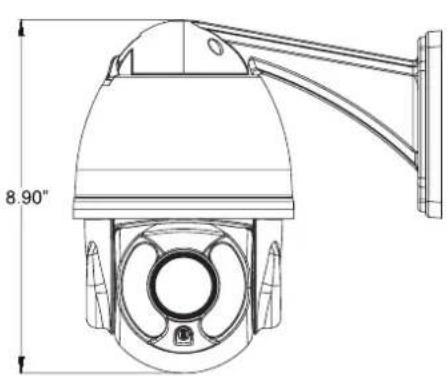
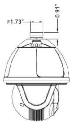
| Dimensions | 8.9" (H) x 5.55" (Dia) / 9.29" (D) with Included Wall Mount |
natural_image
Technical line drawing of a surveillance camera with 8.90-inch height dimension标注 (no text or symbols on the diagram itself)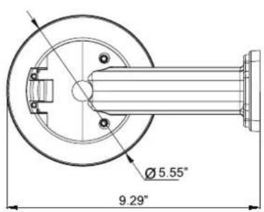
VT-TPTZ18HR-4N Specifications
| Sensor | 1/3" 4.0 MegaPixel CMOS Sensor |
| Resolution | 2592x1520 @ 22fps / 2304x1296 @ 30fps |
| LEDs | 10 Integrated High Power IR LEDs |
| IR distance | Up to 500' IR Range |
| Support ambient light detection | IR illumination on 1-25 grades selectable; |
| Lens | Built-in 4.8mm to 84mm Lens offering 18x Optical Zoom |
| View of Angle | D : WIDE 68.5°±5% TELE 4.2°±5%; H : WIDE 54.8°±5% TELE 3.4°±5%; V : WIDE 41°±5% TELE 2.5°±5% |
| Min. Illumination | 0.05 lx /F2(color), 0.005 lx /F2 (W/B)0.Lux/F2 IR ON |
| Day/Night Operation | True Day/Night by IR Cut Filter |
| Digital Noise Reduction | 2D-DNR |
| Pan range | 360° |
| Pan range | 90° |
| Auto Flip | Horizontal 180°, Vertical 93° |
| Horizontal Rotation Speed | 480/s |
| Tilt Rotation Speed | 160°/s |
| Preset Points | 220 |
| Go to Preset Speed | 01-64 levels available |
| 360° Scan | 1-64 grades setting available |
| A-B Scan | User programmable |
| A-B Scan Speed | 0-64 levels setting available |
| Park Time | 1-60mins setting available |
| Alarm | 4 alarm input/ 2 alarm output ( optional) |
| Dwell Preset | 2-60s interval available |
| Guard Tours | 8 groups |
| Guard Points | Max.16 points, dwell time user selectable |
| Pattern Scans | 4 |
| Pattern Scan Record | Max.15 minutes, max.512 commands |
| Time Scheduling Function | 6 tasks |
| PWR On Action | Memory/Pattern 1/Tour 1/360° scan/A-B scan/Preset 1-8/None |
| Communication Protocol | Pelco-D, Pelco-P |
| Baud Rate | 1200/2400/4800/9600bps |
| Operating Temperature | -40°F ~ 140°F (-40°C ~ 60°C) with included outdoor housing |
| Input Voltage | 12VDC |
| Lightning Protection | Transient voltage 6000V |
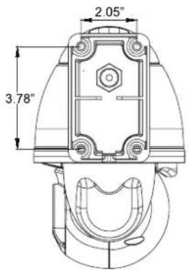
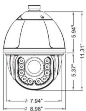
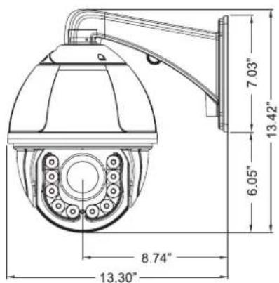
| Dimensions | 13.42" (H) x 8.98" (Dia) / 13.3" (D) with Included Wall Mount |

TRANSCENDENT
VITEK
CONSIDER THESE OTHER GREAT TRANSCENDENT PRODUCTS!
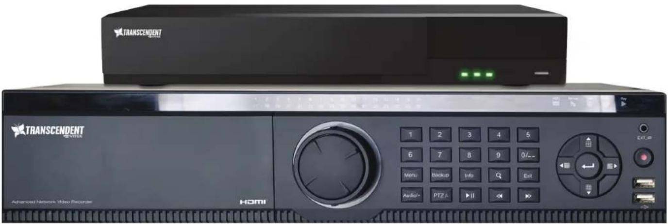
VT-TNR Series
Transcendent Series 4, 8, 32, and 64 Channel 5 MegaPixel H.265 Real Time Network Video Recorders with 4K HDMI Output

FEATURES
• 4, 8, 32, and 64 Channel Stand-alone Real-time IP Network Video Recorders
• Full 5 Megapixel Real-time recording & playback
• 4K HDMI & VGA Video Outputs
• H.265 / H.264 Video Compression
- Plug and Play & Auto configuration for many leading ONVIF compliant IP Camera models
- Internal PoE Switch (VT-TNR414P, VT-TNR818P, and VT-TNR3216P)
• 1 Gigabit LAN
- Pentaplex: Live Display / Record / Playback / Backup / Remote Access
• Supports SATA2/SATA3 HDD
- Applications for iOS® & Android®
- Remote Viewing over the Internet via Web Browser or LAN
• Mac OS® Client & CMS Central Management Software Included
• Supports both Dynamic and Static IP Addresses
• Web-based remote configuration
• Control locally via Front Panel Controls, USB Mouse, or with the Included IR Remote control
natural_image
Four-panel collage showing urban infrastructure: elevated railway, elevated highway, elevated road with greenery, and modern building complex (no visible text or symbols)Remote Viewing with Web Browsers
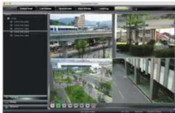
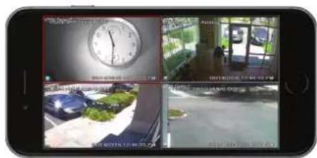
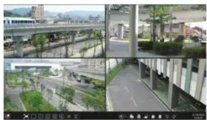
Remote Viewing Using Mac OSXLocal Mapping Available ViewingPhotoiPad, & Android Devices
VITEK LIMITED PRODUCT WARRANTY
VITEK products carry a three (3) year limited warranty. Digital recording and storage products are also warranted for 3 years except for the hard drives which carry their own independent factory warranty from the hard drive manufacturer. VITEK warrants to the purchaser that products manufactured by VITEK are free of any rightful claim of infringement or the like, and when used in the manner intended, will be free of defects in materials and workmanship for a period of three (3) years, or as otherwise stated above, from the date of purchase by the end user. This warranty is non-transferable and extends only to the original buyer or end user customer of a Vitek Authorized Reseller.
This warranty shall not apply to repairs or replacements necessitated by any cause beyond the control of VITEK, including but not limited to, acts of nature, improper installation, excess moisture, misuse, lack of proper maintenance, accident, voltage fluctuations, or any unauthorized tampering, repairs or modifications. This warranty becomes VOID in the event of alteration, defacement, or removal of serial numbers.
Within the first 6 months of purchase, VITEK will replace or credit any defective product at the request of the customer (subject to availability) with a new product that equals or exceeds the performance of the original product purchased.
Within the first 6 months of purchase, at its sole discretion, VITEK may issue an advance replacement for a defective product; however, all related costs including, but not limited to shipping and/or delivery charges will be the responsibility of the customer. If upon return inspection a product is determined to be in good working order or shows evidence of misuse, the customer will be responsible for full payment of the original product purchased as well as the replacement product.
Beyond the first 6 month period for the remainder of the warranty, VITEK'S responsibility shall be limited to repairing the defective product, including all necessary parts and related labor costs. At its sole discretion, VITEK may choose to either exchange a defective product or issue a merchandise credit towards future product purchases. Any replacement parts furnished in connection with this warranty shall be warranted for a period not to exceed the remaining balance of the original equipment warranty.
A Return Authorization number or “RA” number must be obtained prior to the return of any item for repair, replacement, or credit. VITEK requires that this “RA” number be clearly printed on the outside of the shipping carton to avoid refusal of said shipment. The Return Authorization number expires after 30 days. Products returned after the 30 day period will be subject to refusal. Shipping charges, if any, must be prepaid. A copy of the bill of sale (or invoice of purchase), together with a complete written explanation of the problem must accompany all returns.
Vitek makes no warranty or guarantee whatsoever with respect to products sold or purchased through unauthorized sales channels. Warranty support is available only if product is purchased through a Vitek Authorized Reseller.
- FEATURES
- VT-TKB D1
- VT-TPT-C N MT
- VT-TPT-PLMT
- VT-T PT-P D M2
- VT-T PTPD M1
- VT-T PT-J B01
- WARNINGS AND CAUTIONS
- WARNING
- CAUTION
- EXPLANATION OF GRAPHICAL SYMBOLS
- TABLE OF CONTENTS
- PRODUCT INTRODUCTION....3
- INSTALLATION....4
- FUNCTION INSTRUCTION....26
- OSD MENU 27
- PRODUCT INTRODUCTION
- PACKAGE CONTENTS
- FUNCTION DESCRIPTION
- 3D Allocation
- Pattern
- Auto Flip
- Focus
- BLC (Back Light Compensation)
- Iris Control
- Ratio Speed
- Scan
- Preset
- Guard Tour Scan
- A-B Scan
- Power Off Memory
- Park Action
- INSTALLATION
- INSTALLATION
- WALL MOUNTED
- PTZ Connection
- Connecting the Device
- Setting IE Browser
- Install Active X
- Video Browse
- PTZ Control
- PTZ Function
- Common Shortcuts
- SETTING
- System
- Network
- Camera
- Basic Settings:
- Exposure Settings:
- Effect Settings:
- Video & Audio
- Motion Detection:
- PTZ Function
- Auto Tour:
- Alarm
- User
- log
- FUNCTION INSTRUCTION
- OSD MENU
- SYSTEM INFORMATION
- DOME
- Communication
- IR Display
- Guard Tours
- A-B Scan
- Pan Scan
- Pattern
- Park Action
- Privacy Zone(Optional)
- Advanced
- CAMERA
- DISPLAY
- LANGUAGE
- TIMING TASK
- ALARM (OPTIONAL)
- TRANSCENDENT
- VITEK
- CONSIDER THESE OTHER GREAT TRANSCENDENT PRODUCTS!
- VT-TNR Series
- VITEK LIMITED PRODUCT WARRANTY
Brand : Vitek
Model : VT-TPTZ18HR-4N
Category : Uncategorized