AlertWerks EME155A - Uncategorized Black Box - Free user manual and instructions
Find the device manual for free AlertWerks EME155A Black Box in PDF.


| Type of Product | ServSensor 4 with PoE and Temperature Sensor |
| Model Number | EME155A |
| Brand | Black Box |
| Color | Black |
| Enclosure Material | Steel |
| Mounting | 1U rackmount |
| Dimensions (H x W x D) | 1.8 x 8.5 x 5.4 inches (4.6 x 21.6 x 13.7 cm) |
| Weight | 3.53 lb (1.6 kg) |
| Power Input | 7.5-9 VDC, 1.2 A / PoE 802.3af |
| Power Consumption | 1.12 W, 0.13 A |
| Operating Temperature Range | -31 to +131 °F (-35 to +55 °C) |
| Operating Humidity Range | 20 to 80% noncondensing |
| Network Interface | 1 RJ-45 10 Mbps full-duplex Ethernet/PoE input |
| Sensor Inputs | 4 RJ-45 intelligent sensor ports |
| Indicators | Power, Link, Activity, 4 Online LEDs, 4 Status LEDs |
| Operating System | Proprietary, similar to Linux with TCP/IP stack, Web server, SNMP, email |
| Included Accessories | Temperature sensor, power supply, power cable, CAT5 crossover cable, CD with manual |
| Data Logging Capacity | 8,640 points per sensor |
| Notifications | SNMP traps and email alerts |
| Compliance | IEEE 802.3af, FCC Class A, Industry Canada Class A |
Frequently Asked Questions - AlertWerks EME155A Black Box
User questions about AlertWerks EME155A Black Box
0 question about this device. Answer the ones you know or ask your own.
Ask a new question about this device
Download the instructions for your Uncategorized in PDF format for free! Find your manual AlertWerks EME155A - Black Box and take your electronic device back in hand. On this page are published all the documents necessary for the use of your device. AlertWerks EME155A by Black Box.
USER MANUAL AlertWerks EME155A Black Box
AlertWerks™ ServSensor Jr. and ServSensors
Monitor environmental variations, power, physical threats, and security.
Includes a proprietary operating system that is similar to Linux®, with TCP/IP stack, Web server, e-mail, and full SNMP functionality.
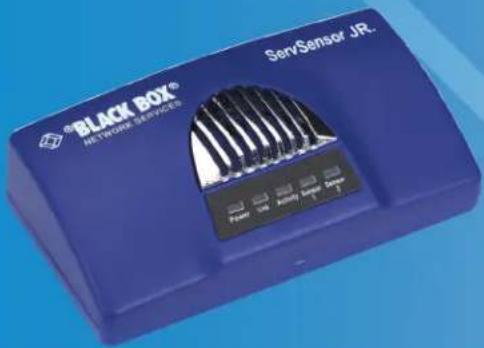
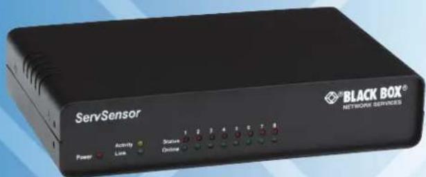
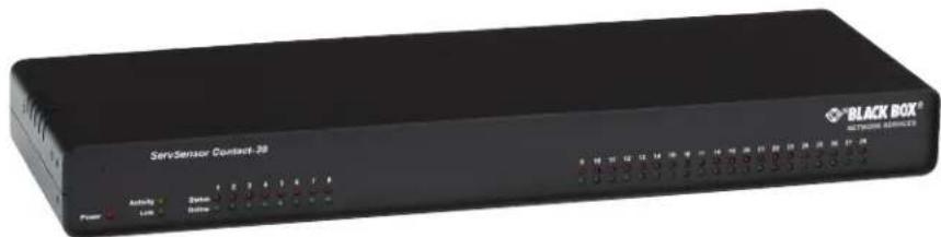
Trademarks Used in this Manual
Black Box and the Double Diamond logo are registered trademarks, and AlertWerks is a trademark, of BB Technologies, Inc.
CA-Unicenter is a registered trademark of CA, Inc.
GNU is a trademark of Free Software Foundation.
HP is a registered trademark of Hewlett-Packard Company.
OpenView is a registered trademark of Hewlett-Packard Development Company.
IBM and Tivoli are registered trademarks of International Business Machines Corporation.
Linux is a registered trademark of Linus Torvalds.
Internet Explorer, Microsoft, Excel, MS-DOS, and Windows are registered trademarks of Microsoft Corporation.
Kiwi is a trademark of SolarWinds Worldwide, LLC.
Any other trademarks mentioned in this manual are acknowledged to be the property of the trademark owners.
We're here to help! If you have any questions about your application or our products, contact Black Box Tech Support at 724-746-5500 or go to blackbox.com and click on "Talk to Black Box." You'll be live with one of our technical experts in less than 30 seconds.
Federal Communications Commission and Industry Canada Radio Frequency Interference Statements
This equipment generates, uses, and can radiate radio-frequency energy, and if not installed and used properly, that is, in strict accordance with the manufacturer's instructions, may cause interference to radio communication. It has been tested and found to comply with the limits for a Class A computing device in accordance with the specifications in Subpart B of Part 15 of FCC rules, which are designed to provide reasonable protection against such interference when the equipment is operated in a commercial environment. Operation of this equipment in a residential area is likely to cause interference, in which case the user at his own expense will be required to take whatever measures may be necessary to correct the interference.
Changes or modifications not expressly approved by the party responsible for compliance could void the user's authority to operate the equipment.
This digital apparatus does not exceed the Class A limits for radio noise emission from digital apparatus set out in the Radio Interference Regulation of Industry Canada.
- Specifications....6
- Overview 8
2.1 Introduction 8
2.1.1 What is the AlertWerks ServSensor? 8
2.1.2 Available Models 8
2.1.3 How to Use this Manual 9
2.2 Features 9
2.3 What's Included....9
2.4 Hardware Description 13
2.4.1 ServSensor Jr. (EME102A-R2, EME103A-R2, EME104A-R2, EME152A, EME153A, EME154A).... 13
2.4.2 ServSensor 4 (EME105A, EME106A, EME155A) 14
2.4.3 ServSensor 8 (EME108A-R2, EME109A-R2, EME110A-R2, EME158A) 15
2.4.4 ServSensor X20 (EME111A-20-R2, EME111A-60-R2, EME112A-20-R2, EME112A-60-R2, EME113A-20-R2, EME113A-60-R2).... 16
2.4.5 ServSensor 8-X20 20 Extra Dry Contact Inputs....17
- Installation 18
3.1 Assigning an IP Address 18
3.2 Testing Your New IP Address 21
3.3 Upgrading the Firmware 22
- Setting up a Sensor and Downloading Sensor Data....27
4.1 Basic Setup 27
4.2 Downloading Sensor Data 30
- Notifications 33
5.1 Setting Up a Trap 33
5.2 Setting Up E-mail Notifications 34
- System Settings 38
6.1 Network Settings 38
6.2 System Tab....40
- Making Your Unit Visible to the Internet....46
7.1 Simple Setup 46
7.2 Setting Up Your PC's Routing Table 46
- Frequently Asked Questions (FAQs)......47
1. Specifications
Color — EME102A-R2–EME104A-R2, EME152A–EME154A: Blue; EME105A–EME106A, EME155A, EME108A-R2–EME110A-R2, EME158A, EME111A-20-R2, EME111A-60-R2, EME112A-20-R2, EME112A-60-R2, EME113A-20-R2, EME113A-60-R2,: Black
Default IP Address — 192.168.0.100
Enclosure — EME102A-R2–EME104A-R2, EME152A–EME154A: Plastic housing; EME105A–EME106A, EME155A, EME158A, EME108A-R2–EME110A-R2, EME111A-20-R2, EME111A-60-R2, EME112A-20-R2, EME112A-60-R2, EME113A-20-R2, EME113A-60-R2: Steel housing
Mounting — EME102A-R2–EME104A-R2, EME152A–EME154A: Shelf- or DIN-rail mounting; EME105A–EME106A, EME155A, EME158A, EME108A-R2–EME110A-R2, EME111A-20-R2, EME111A-60-R2, EME112A-20-R2, EME112A-60-R2, EME113A-20-R2, EME113A-60-R2: 1U rackmount
Number of Dry Contacts — EME111A-20-R2-EM113A-20-R2: 20; EME111A-60-R2-EME113A-60-R2: 60
Operating System — Proprietary, similar to Linux®, including TCP/IP stack, Web server, e-mail, and full SNMP functionality Operating Environment — Indoor
Standards — EME152A–EME154A, EME158A: IEEE 802.3af compliant
Connectors — EME102A-R2–EME104A-R2: Network: (1) RJ-45 10-Mbps full-duplex Ethernet; Sensor Input: (2) RJ-45; Power: (1) 7.5-VDC power connector; EME152A–EME154A: Network: (1) RJ-45, 10-Mbps full-duplex Ethernet /PoE input, Sensor Input: (2) RJ-45; Power: (1) 7.5-VDC power connector; EME105A–EME106A: Network: (1) RJ-45 10-Mbps full-duplex Ethernet, Sensor Input: (4) RJ-45, Power: (1) 7.5-VDC input; EME155A: Network: (1) RJ-45 10-Mbps full-duplex Ethernet/PoE input, Sensor Input: (4) RJ-45, Power: (1) 7.5-VDC input; EME108A-R2–EME110A-R2: Network: (1) RJ-45 10-Mbps full-duplex Ethernet, Sensor Input: (8) RJ-45, Power: (1) 7.5-VDC input; EME158A: Network: (1) RJ-45 10-Mbps full-duplex Ethernet/PoE input, Sensor Input: (8) RJ-45, Power: (1) 7.5-VDC input; EME111A-20-R2–EME113A-20-R2: Network: (1) RJ-45 10-Mbps full-duplex Ethernet/PoE input, Sensor Input: (8) RJ-45, Power: (1) 7.5-VDC input, Dry contact: (20) 2-wire terminal blocks; EME111A-60-R2–EME113A-60-R2: Network: (1) RJ-45 10-Mbps full-duplex Ethernet/PoE input, Sensor Input: (8) RJ-45, Power: (1) 7.5-VDC input, Dry contact: (60) 2-wire terminal blocks Indicators — EME102A-R2–EME104A-R2, EME152A–EME154A: (5) LEDs: Power, Link, Activity, Sensor 1, Sensor 2
Temperature Tolerance — Operating: -31 to +131 F (-35 to 55°C)
Relative Humidity — Operating: 20 to 80% noncondensing
Power — EME102A-R2–EME104A-R2, EME108A-R2–EME110A-R2: Power: 7.5–9 VDC, Consumption: 1.2 amps, 1.125 watts, 0.15 A; EME152A–EME154A, EME158A: Power: 7.5–9 VDC, Consumption: 1.2 amps, 1.125 watts, 0.15 A, PoE: 802.3af; EME105A–EME106A: Power: 7.5–9 VDC, Consumption: 1.2 amps, 1.12 watts, 0.13 A; EME155A: Power: 7.5–9 VDC, Consumption: 1.2 amps, 1.12 watts, 0.13 A, PoE: 802.3af; EME111A-20-R2–EME113A-20-R2: Power: 7.5–9 VDC, Consumption: 3 amps, 1.9 watts, 0.21 A; EME111A-60-R2–EME113A-60-R2: Power: 7.5–9 VDC, Consumption: 3 amps, 2.9 watts, 0.32 A;
Size — EME102A-R2–EME104A-R2, EME152A–EME154A: 0.5"H x 2.5"W x 1.25"D (1.3 x 6.3 x 3.2 cm); EME105A–EME106A: EME108A-R2–EME110A-R2, EME155A, EME158A: 1.8"H (1U) x 8.5"W x 5.4"D x (4.6 x 21.6 x 13.7 cm), EME111A-20-R2–EME112A-20-R2, EME112A-60-R2–EME113A-60-R2: 1.7"H (1U) x 18"W x 5"D (4.3 x 45.7 x 12.7 cm)
Weight — EME102A-R2–EME104A-R2, EME152A–EME154A: 0.66 lb. (0.3 kg); EME105A–EME106A, EME155A: 3.53 lb. (1.6 kg); EME108A-R2–EME110A-R2, EME158A: 3.85 lb. (1.75 kg); EME111A-20-R2–EME113A-20-R2: 4.96 lb. (2.25 kg); EME111A-60-R2–EME113A-60-R2: 7.17 lb. (3.25 kg)
2. Overview
2.1 Introduction
2.1.1 What is the AlertWerks ServSensor?
The AlertWerks ServSensors are intelligent devices for monitoring environmental variables, power, physical threats, and security. The units are IP based and have a Web interface for configuration. Included in this is a TCP/IP stack, Web server, full SNMP, and e-mail support.
Any of our Intelligent Sensors can be connected via the RJ-45 connections (excluding our 8-port, sensor-controlled relay, thermocouple, or PMS sensors), or you can add dry contact connection for monitoring UPS, security systems, and air conditioning status.
2.1.2 Available Models
Table 2-1. Available models.
| Part Number Name | |
| EME102A-R2 ServSensor Jr. | |
| EME103A-R2 ServSensor Jr. with Temperature Sensor | |
| EME104A-R2 ServSensor Jr. with Dual Temperature/Humidity Sensor | |
| EME152A ServSensor Jr. with PoE | |
| EME153A ServSensor Jr. with PoE and Temperature Sensor | |
| EME154A ServSensor Jr. with PoE and Dual Temperature/Humidity Sensor | |
| EME105A ServSensor 4 | |
| EME106A ServSensor 4 with Temperature Sensor | |
| EME155A ServSensor 4 with PoE and Temperature Sensor | |
| EME108A-R2 ServSensor 8 | |
| EME109A-R2 ServSensor 8 with Temperature Sensor | |
| EME110A-R2 ServSensor 8 with Dual Temperature/Humidity Sensor | |
| EME111A-20-R2 | ServSensor 8 with 20 Dry Contacts |
| EME111A-60-R2 ServSensor 8 with 60 Dry Contacts | |
| EME112A-20-R2 ServSensor 8 with 20 Dry Contacts and Temperature Sensor | |
| EME112A-60-R2 ServSensor 8 with 60 Dry Contacts and Temperature Sensor | |
| EME113A-20-R2 | ServSensor 8 with 20 Dry Contacts and Dual Temperature/Humidity Sensor |
| EME113A-60-R2 ServSensor 8 with 60 Dry Contacts and Dual Temperature/Humidity Sensor | |
What's the difference between the ServSensor Jr., ServSensor 4, and the ServSensor 8?
The ServSensor Jr. is a small unit with two RJ-45 sensor inputs, the ServSensor 4 has four RJ-45 sensor inputs, and the ServSensor 8 has eight RJ-45 inputs.
What's the difference between the ServSensor 8 and the ServSensor X20?
The ServSensor X20 has eight RJ-45 intelligent sensor ports AND 20 extra dry contact inputs; the ServSensor 8 only has eight 8 RJ-45 sensor ports. For more on these extra dry contacts, see Section 2.4.5.
2.1.3 How to Use this Manual
This manual is a step-by-step guide on how to get your unit set up and functioning. It will introduce the primary features of the unit by way of tutorials. You can either go through the whole procedure from start to finish, or, if you wish, use each tutorial as a standalone lesson. The start of each lesson gives an “entry point profile,” which details how to get to the start point of the lesson and assumes previous knowledge through completion of previous tutorials.
NOTE: Throughout this manual, you will find notes in each section that will relate to the information you are reviewing. Also, Chapter 8 contains covers common questions and problems you may encounter. If you need any further assistance, contact Black Box Technical Support at 724-746-5500 or info@blackbox.com.
2.2 Features
- Support all major communications protocols.
- Embedded Web server.
- Support up to (2) intelligent sensors (EME102A-R2, EME103A-R2, EME104A-R2, EME152A, EME153A, EME154A only).
- Support up to (4) intelligent sensors (EME105A, EME106A, EME155A).
- Support up to (8) intelligent sensors (EME108A-R2, EME109A-R2, EME110A-R2).
- ServSensor Jr. (EME102A-R2, EME103A-R2, EME104A-R2, EME152A, EME153A, EME154A only) supports up to 10 dry contact inputs (use two EME1DC-XXX sensors and the EME1DC-UPG).
- Comply with SNMP v1 standard.
- Include SNMP MIB.
- Include SNMP utilities for setting and getting parameters.
- Support SNMP polling to allow sensor values to be collected and graphed.
- Send trap notifications.
- Send e-mail notifications.
- Include sensor description and sensor values in notifications.
- User-configurable sensor thresholds.
- Use the optional "Continuous Time" feature to eliminate false alerts and notifications.
- Optional IEEE 802.3af Power over Ethernet (PoE) compliant (EME152A, EME153A, and EME154A only).
• 100-Mbps full-duplex Ethernet port.
2.3 What's Included
Your package should include the following items. If anything is missing or damaged, contact Black Box Technical Support at 724-746-5500 or info@blackbox.com.
EME102A-R2:
- ServSensor Jr.
- CD containing this user's manual in PDF format
• (1) power supply
• (1) RJ-45 to RJ-45 patch cord, 5-ft. (1.5-m)
EME103A-R2:
- ServSensor Jr.
• Temperature Sensor (EME1T1-001) - CD containing this user's manual in PDF format
• (1) power supply
• (1) RJ-45 to RJ-45 patch cord, 5-ft. (1.5-m)
EME104A-R2:
- ServSensor Jr.
• Dual Temperature/Humidity Sensor (EME1TH1-001) - CD containing this user's manual in PDF format
• (1) power supply
• (1) RJ-45 to RJ-45 patch cord, 5-ft. (1.5-m)
EME152A:
- ServSensor Jr. PoE Hub
- Power supply
- Power cable
• CAT5 crossover patch cable - CD containing this user's manual in PDF format
EME153A:
- ServSensor Jr. PoE Hub
• Temperature Sensor (EME1T1-001) - Power supply
- Power cable
• CAT5 crossover patch cable - CD containing this user's manual in PDF format
EME154A:
- ServSensor Jr. PoE Hub
• Dual Temperature/Humidity Sensor (EME1TH1-001) - Power supply
- Power cable
• CAT5 crossover patch cable - CD containing this user's manual in PDF format
EME108A-R2:
- ServSensor 8
- Power supply
• (1) 5-ft. (1.5-m) RJ-45 to RJ-45 cable
• (1) set of rackmount brackets with hardware - CD containing this user's manual in PDF format
EME109A-R2:
- ServSensor 8
• Temperature Sensor with 1-ft. (3.2-m) cable (EME1T1-001) - Power supply
• (1) 5-ft. (1.5-m) RJ-45 to RJ-45 cable
• (1) set of rackmount brackets with hardware - CD containing this user's manual in PDF format
EME110A-R2:
- ServSensor 8
- Dual Temperature/Humidity Sensor with 1-ft. (3.2-m) cable (EME1TH1-001)
- Power supply
• (1) 5-ft. (1.5-m) RJ-45 to RJ-45 cable
• (1) set of rackmount brackets with hardware - CD containing this user's manual in PDF format
EME111A-20-R2:
- ServSensor 8 with 20 dry contact ports
- Power supply
• (1) 5-ft. (1.5-m) RJ-45 to RJ-45 cable
• (1) set of rackmount brackets with hardware - CD containing this user's manual in PDF format
EME111A-60-R2:
- ServSensor 8 with 60 dry contact ports
- Power supply
• (1) 5-ft. (1.5-m) RJ-45 to RJ-45 cable
• (1) set of rackmount brackets with hardware - CD containing this user's manual in PDF format
EME112A-20-R2:
- ServSensor 8 with 20 dry contact ports
• Temperature Sensor with 1-ft. (3.2-m) cable (EME1T1-001)
• (1) 5-ft. (1.5-m) RJ-45 to RJ-45 cable
• (4) terminal blocks (installed)
• (1) set of rackmount brackets with hardware - CD containing this user's manual in PDF format
EME112A-60-R2:
- ServSensor 8 with 60 dry contact ports
• Temperature Sensor with 1-ft. (3.2-m) cable (EME1T1-001)
• (1) 5-ft. (1.5-m) RJ-45 to RJ-45 cable
• (4) terminal blocks (installed)
• (1) set of rackmount brackets with hardware - CD containing this user's manual in PDF format
EME113A-20-R2:
- ServSensor 8 with 20 dry contact ports
- Dual Temperature/Humidity Sensor with 1-ft. (3.2-m) cable (EME1TH1-001)
• (1) 5-ft. (1.5-m) RJ-45 to RJ-45 cable
• (4) terminal blocks (installed)
• (1) set of rackmount brackets with hardware - CD containing this user's manual in PDF format
EME113A-60-R2:
- ServSensor 8 with 60 dry contact ports
- Dual Temperature/Humidity Sensor with 1-ft. (3.2-m) cable (EME1TH1-001)
• (1) 5-ft. (1.5-m) RJ-45 to RJ-45 cable
• (4) terminal blocks (installed)
• (1) set of rackmount brackets with hardware - CD containing this user's manual in PDF format
2.4 Hardware Description
2.4.1 ServSensor Jr. (EME102A-R2, EME103A-R2, EME104A-R2, EME152A, EME153A, EME154A)
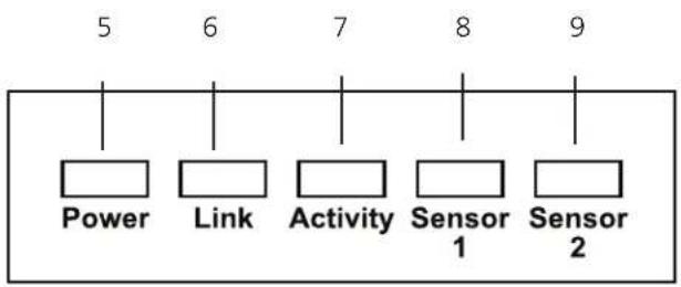
Figures 2-1 and 2-2 show the front and top panels of the ServSensor Jr. Table 2-2 describes its components.
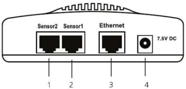
Figure 2-1. ServSensor Jr. front panel.
flowchart
graph TD
    A["Power"] --> B["Link"]
    B --> C["Activity"]
    C --> D["Sensor 1"]
    D --> E["Sensor 2"]
Figure 2-2. ServSensor Jr. top panel.
Table 2-2. ServSensor Jr. components.
| Number Component Description | |
| 1 (1) RJ-45 port Links to Sensor2 | |
| 2 (1) RJ-45 port Links to Sensor1 | |
| 3 (1) RJ-45 port Connects to 10BASE-T network. | |
| 3 Barrel connector Links to 7.5-VDC power. | |
| 5 Power LED Lights when power is on. | |
| 6 Link LED Lights when a link is established. | |
| 7 Activity LED Lights when the unit is active. | |
| 8 Sensor 1 LED Lights when sensor 1 is active. | |
| 9 Sensor 2 LED Lights when sensor 2 is active. |
NOTE: The EME152A–EME154A use Power over Ethernet (PoE) instead of a power supply jack.
2.4.2 ServSensor 4 (EME105A, EME106A, EME155A)
Figures 2-3 and 2-4 show the front and back panels of the ServSensor 4. Table 2-3 describes its components.
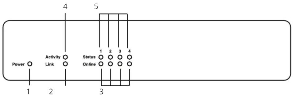
Figure 2-3. ServSensor 4 front panel.
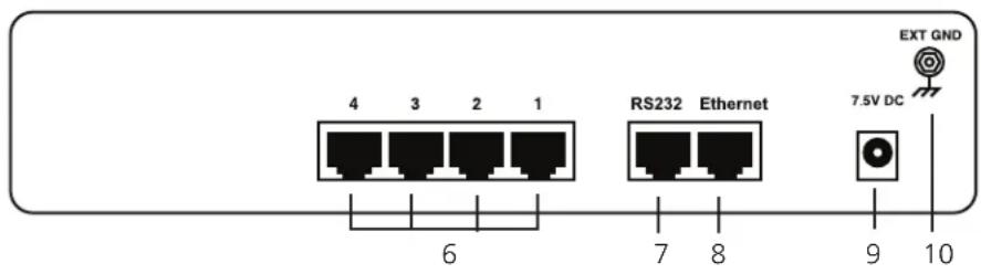
Figure 2-4. ServSensor 4 back panel.
Table 2-3. ServSensor 4 components.
| Number Component Description | ||
| 1 (1) Power LED Lights when power is on. | ||
| 2 (1) Link LED Lights when a link is present. | ||
| 3 (4) Online LEDs Lights when the sensor is on-line. | ||
| 4 (1) Activity LED Lights when the unit is active. | ||
| 5 (4) Status LEDs Lights when the sensor is in alarm state. | ||
| 6 (4) RJ-45 ports Sensor ports | ||
| 7 (1) RJ-45 port Links to RS-232 device. | ||
| 8 (1) RJ-45 port Links to Ethernet. | ||
| 9 (1) barrel connector Links to 7.5-VDC power. | ||
| 10 | Ground connector | Links to external ground. |
2.4.3 ServSensor 8 (EME108A-R2, EME109A-R2, EME110A-R2. EME158A)
Figures 2-5 and 2-6 show the front and back panels of the ServSensor 8. Table 2-4 describes its components.
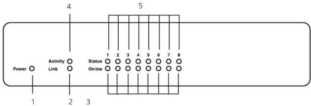
Figure 2-5. ServSensor 8 front panel.
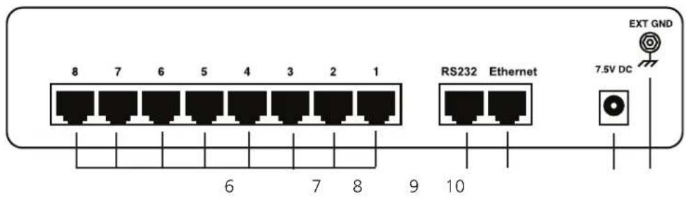
Figure 2-6. ServSensor 8 back panel.
Table 2-4. ServSensor 8 components.
| Number Component Description | ||
| 1 (1) Power LED Lights when power is on. | ||
| 2 (1) Link LED Lights when a network link is present. | ||
| 3 (8) Online LEDs Light when sensors are on-line. | ||
| 4 (1) Activity LED Lights when network is communicating. | ||
| 5 (8) Status LEDs | Light when sensors are in alarm state. | |
| 6 (8) RJ-45 connectors | Sensor ports. | |
| 7 (1) RJ-45 connector | Links to RS-232 device. | |
| 8 (1) RJ-45 connector | Connects to Ethernet. | |
| 9 (1) barrel connector | Connects to power. | |
| 10 | External ground | Grounds the unit. |
2.4.4 ServSensor X20 (EME111A-20-R2, EME111A-60-R2, EME112A-20-R2, EME112A-60-R2, EME113A-20-R2, EME113A-60-R2)
Figures 2-7 and 2-8 show the front and back panels of the ServSensor 8 X20. Table 2-5 describes its components.
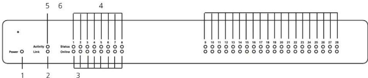
| Number Component | Description | |
| 1 | (1) Power LED | Lights when power is on. |
| 2 | (1) Link LED | Lights when there is a network connection. |
| 3 | (8) Online LEDs | Light when sensors are on-line. |
| 4 | (20) LEDs | Light when dry contacts are on-line. |
| 5 | (1) Activity LED | Lights when there is network traffic. |
| 6 | (8) Status LEDs | Light when sensors are in alarm state. |
| 7 | (20) Dry contact ports | Connect to dry contacts. |
| 8 | (8) RJ-45 ports | Sensor ports. |
| 9 | (1) RJ-45 port | Connects to RS-232. |
| 10 | (1) RJ-45 port | Network connection. |
| 11 | (1) barrel connector | Power connector. |
| 12 | External ground | Ground lug. |
2.4.5 ServSensor 8-X20 20 Extra Dry Contact Inputs
The 20 extra dry contact inputs on, for example, the ServSensor with 20 or 60 DC inputs, can be configured as inputs only up to 5 volts in normal operation. In opto-isolation mode, they can input up to 30 volts DC. This will protect these inputs and the unit from high voltages and spikes.
Opto-isolators provide complete electrical separation between the ServSensor and the dry contact. The base units are therefore protected against possible large voltage spikes caused by lightning for example.
Figure 2-9 shows the JUMPERS (on the dry contact board) set up to provide opto-isolator support. Opto-isolators provide complete electrical separation between the ServSensor and the dry contact.
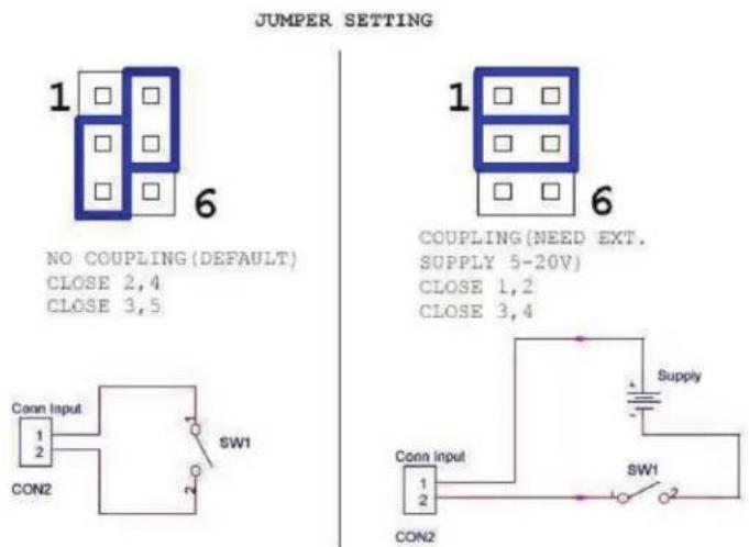
Figure 2-9. Jumpers on the dry contact board.
The OID for the extra dry contact inputs is:- .1.3.6.1.4.1.3854.1.2.2.1.18.1.3.
Extra dry contact input practical applications:
The extra dry contact inputs can be used to monitor many types of equipment, for example, you can run the connection from warning lights on alarm panels to the dry contact inputs, so that when the warning light on the alarm panel is activated, the dry contact is triggered in the unit's Web interface, enabling you to send notifications via e-mails or SNMP traps.
3. Installation
3.1 Assigning an IP Address
These units are plug-and-play devices that will easily connect to your existing network setup. Every unit ships with a default IP address. This is 192.168.0.100. To install your unit, you must first assign it an IP address to match your current network configuration. Before starting this, make sure you have the following items:
-
RJ-45 CAT5 crossover cable with RJ-45 male connection
• A PC with Ethernet card or LAN socket.
• Power socket for the unit to connect to -
Connect the unit via the CAT5 crossover cable to the Ethernet/LAN port on your computer.
- Open your Web browser and go to the default IP address http://192.168.0.100.
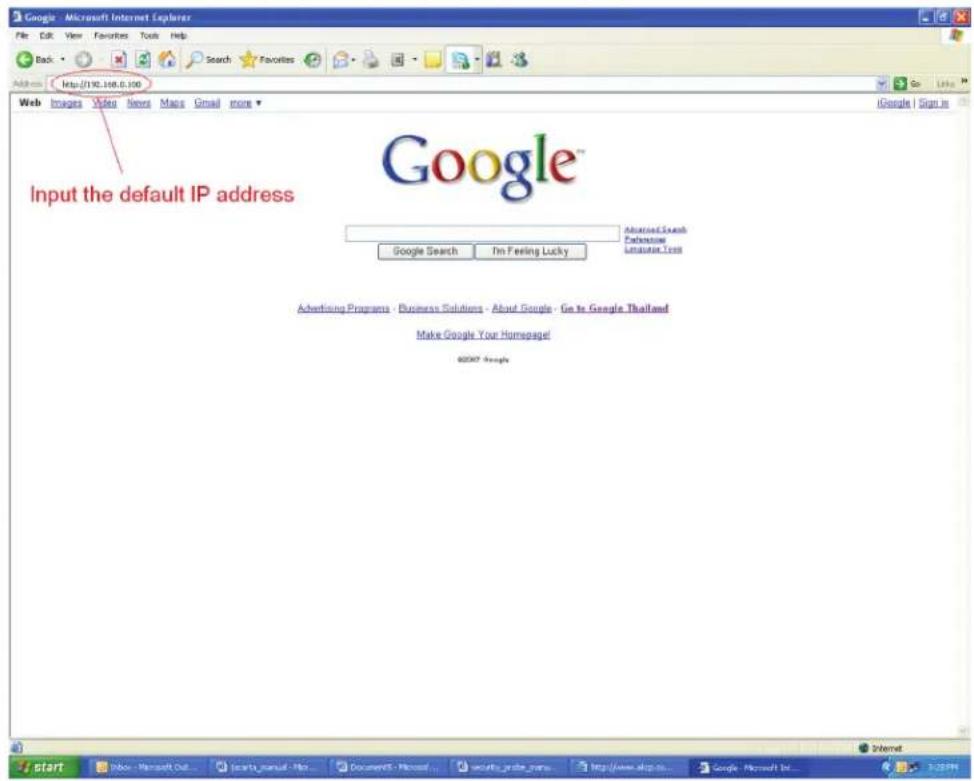
Figure 3-1. Enter default address.
NOTE: In some cases, your computer might not be able to connect to this default IP address. In this situation, you need to set up your computer's routing table to allow access to this.
- You will now be presented with the following login screen.
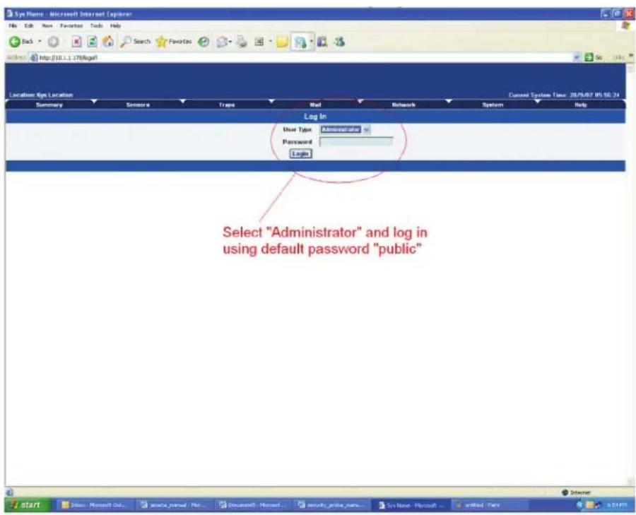
Figure 3-2. Login screen.
- After logging in, you will be taken to the Main Summary page.
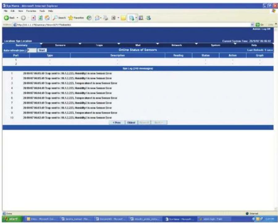
Figure 3-3. Main Summary page.
- From the summary page, select the "Network" tab. Type in your new IP address, then click "Save."
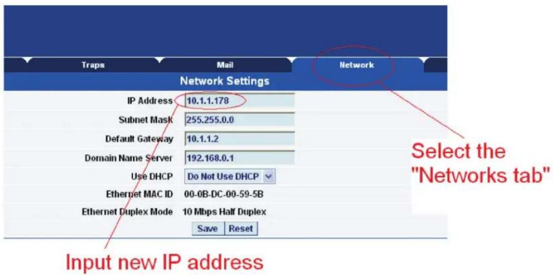
Figure 3-4. Input New Address screen.
3.2 Testing your New IP Address
You now need to test that your new IP address has been assigned successfully. You will do this via the "ping" command.
- Click "Start/Run....." Enter the IP address to ping, then press "Enter."
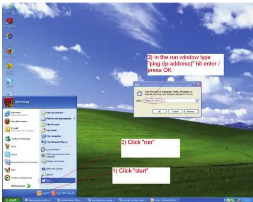
Figure 3-5. Test New Address screen.
- You will now get an MS-DOS® command prompt that shows the ping results. If this is unsuccessful, you will receive a "request timed out" message.
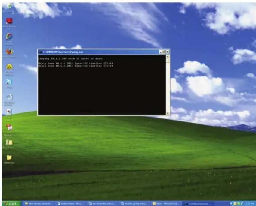
Figure 3-6. Request Timed Out screen.
Having connection problems?
NOTE: The unit's default connection speed is 10 Mbps with half-duplex, so if you are having trouble connecting to the unit, then set the unit to full-duplex mode by using the following SNMP set command.
To set back to halfduplex -->
where "public" is the admin password. "192.168.0.100" is the ServSensor's IP address. The duplex mode is shown on Network Settings page.
NOTE: If you're still having trouble connecting to your ServSensor, or opening your unit's Web interface, see Chapter 8.
3.3 Upgrading the Firmware
We often release new firmware with added capabilities, so we recommend that you upgrade to the latest firmware. To do this, contact Black Box Technical Support at 724-746-5500 or info@blackbox.com and have the MAC address of the hub available. This can be found on a sticker on the base of your unit.
- When you download your firmware, it will come in a zip package. Extract this to your desktop into a folder named firmware. When you open this folder you will see something like the following:
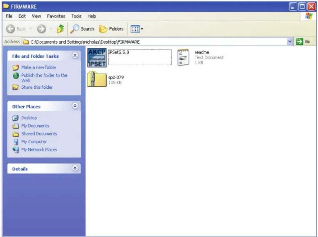
Figure 3-7. Firmware screen.
You can see one of these files is a program named IPSet. This utility will upload the firmware to your unit. Double-click the program to boot it.
- When IPSet loads, you will be met with a screen similar to this:
![Recycle Bit Adder Features Get Started With Card... Google Cable Open Look in: FIRMWARE mp2.379 File name: mp2.379 Files of type: Zip File 1.ppt Open Cancel 1 2 3 4 5 Online help Routing table detail Register your product Exit IPSet Enter password and file to upgrade firmware Mode Automatically Get MAC Manually Enter MAC Firmware Upgrade MAC Address IP Address: 182 168 0 100 Password: Enter firmware file [zip] Send 1 page per package. Browse Update Status](/content/2026/06/1166140/images/af0f501b5e2377d68395c20b96f4c915cc8bf3f89a2f28fef08711a18a1b1d35.jpg)
Figure 3-8. Firmware Upgrade screen.
- Select "firmware upgrade."
- Type in the IP address of your unit.
- Type in your administrator password.
-
Click "Browse," and a new window will pop up.
-
Select the zipped firmware file, and click "Open."
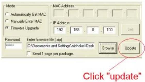
Figure 3-9. Open firmware screen.
- When complete, the message "Upgrade complete" will be displayed.
Problems updating firmware that is very old to the latest release.
You may experience a problem when trying to update your EME102A-R2 or EME108A-R2 to the latest firmware if the firmware on your base unit has not been updated for a very long period of time. Contact Black Box Technical Support at 724-746-5500 or info@blackbox.com.
If you try to update your unit and receive an error in the IPSet utility, then you will need to update your unit. Contact Black Box Technical Support at 724-746-5500 or info@blackbox.com for details.
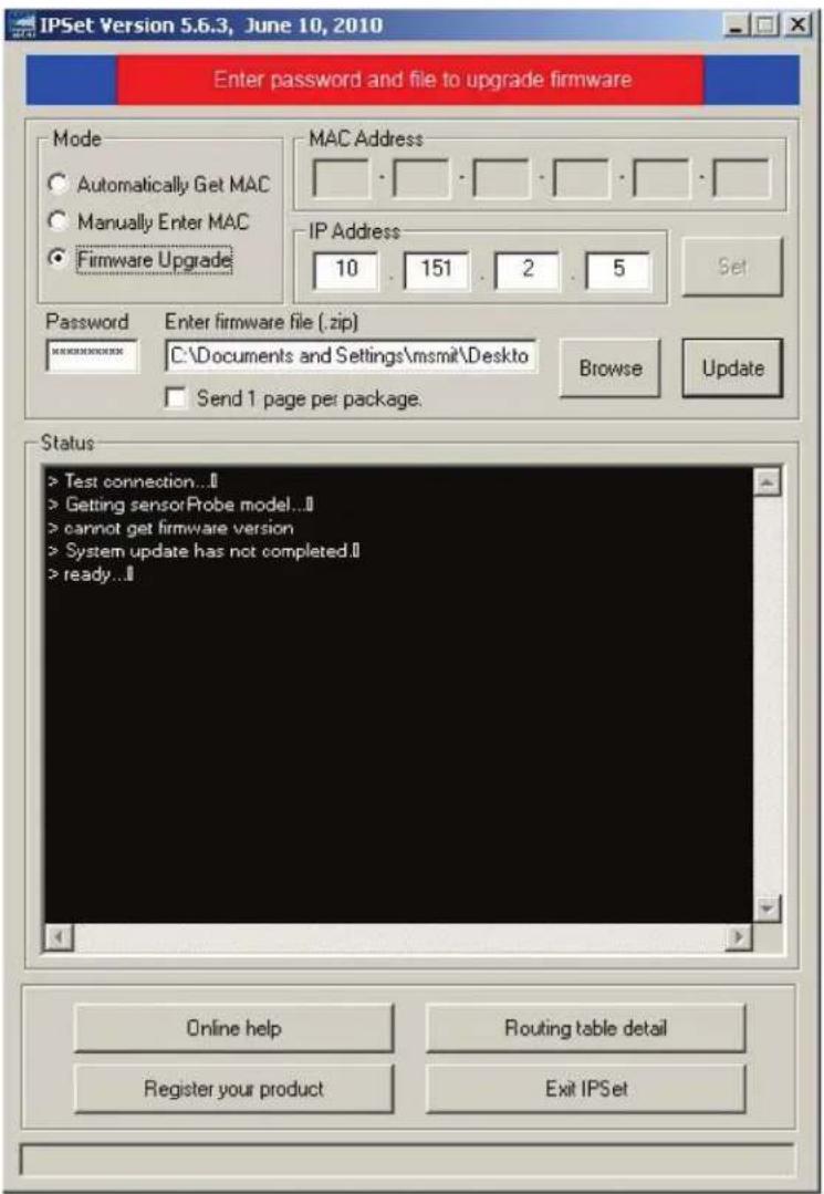
Figure 3-10. Upgrade Firmware screen.
4. Setting up a Sensor and Downloading Sensor Data
For the purposes of this manual and tutorials, we will cover setting up a dual temperature/humidity sensor. The first part of the tutorial will cover the basic installation and settings for the sensor. The second part will explain how to go about setting up various notifications such as SNMP traps.
4.1 Basic Setup
- Plug in your sensor to the RJ-45 Port 1 (Sensor 1). The unit will automatically detect the presence of the sensor and configure it.
- Now return to the Web browser and input the IP address of your unit. Then log in as administrator.
- You will now see the Summary page looking something like this:
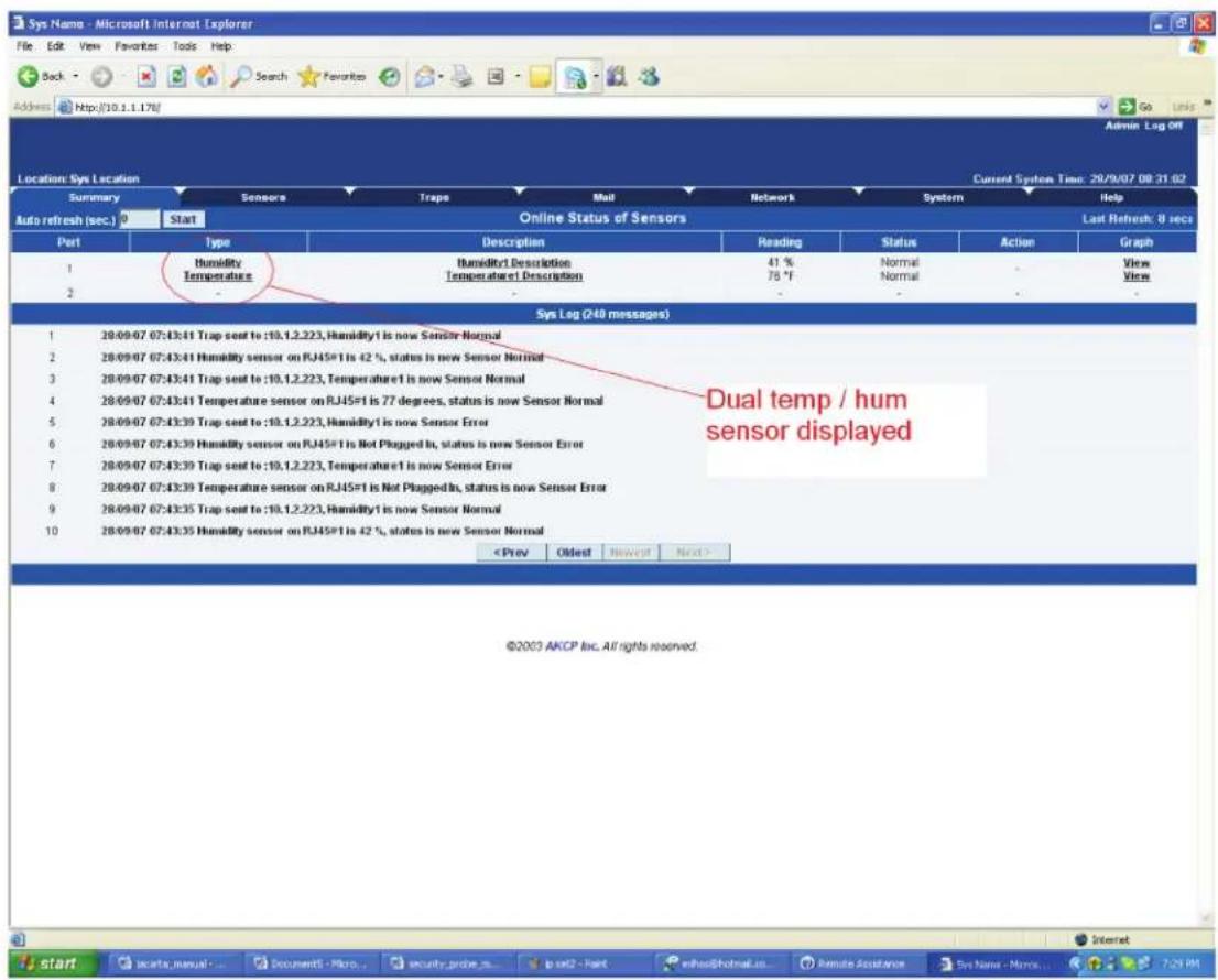
Figure 4-1. Summary page.
You will see the temp/humidity sensor displayed in the Summary page.
- From this page, select the "Sensors" tab. This will bring you to the following page:
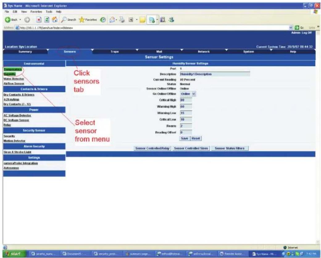
Figure 4-2. Sensors screen.
In this example, we have selected the humidity sensor from the sensor menu on the left. The sensors highlighted in green indicate that they are currently connected to the unit. In this case, you can see there is a temp and humidity sensor connected (dual sensor) and so they are highlighted in green in the menu.
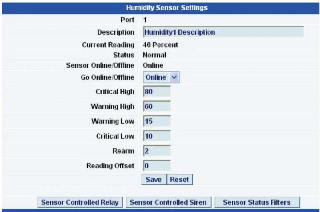
Figure 4-3. Humidity Sensor Settings screen.
- This window is used for configuring the sensor's parameters. These parameters are explained below:
Description—The name of the sensor. Use a meaningful name such as "humidity sensor office1"
Go Online/Offline—This takes the sensor on or offline without unplugging it from the unit.
Critical high—The percentage humidity level that is critically high.
Warning high—The percentage humidity level that is high.
Warning low—The percentage humidity level that is low.
Critical low—The percentage humidity level that is critically low.
Rearm—Used to prevent the sensor from flickering between two states. For example if the "High Warning" threshold for the temperature sensor is set to 80 degrees and the sensor were to vary between 79 and 80 you could be faced with a very large number of e-mails, traps, and events logged. The Rearm parameter prevents this by forcing the temperature to drop by the Rearm before changing the state back to normal. In this example, if Rearm is set to 2, then the sensor would have to drop from 80 down to 77 before the status would change.
Reading offset—This will adjust the reading by your offset amount.
In our example, we have set the parameters as indicated in Figure 4-3. Once you have done this, click on "Save."
NOTE: For information on setting up other sensor types, refer to the manual for your specific sensor. This will give you guidance in setting up the parameters specific to your sensor.
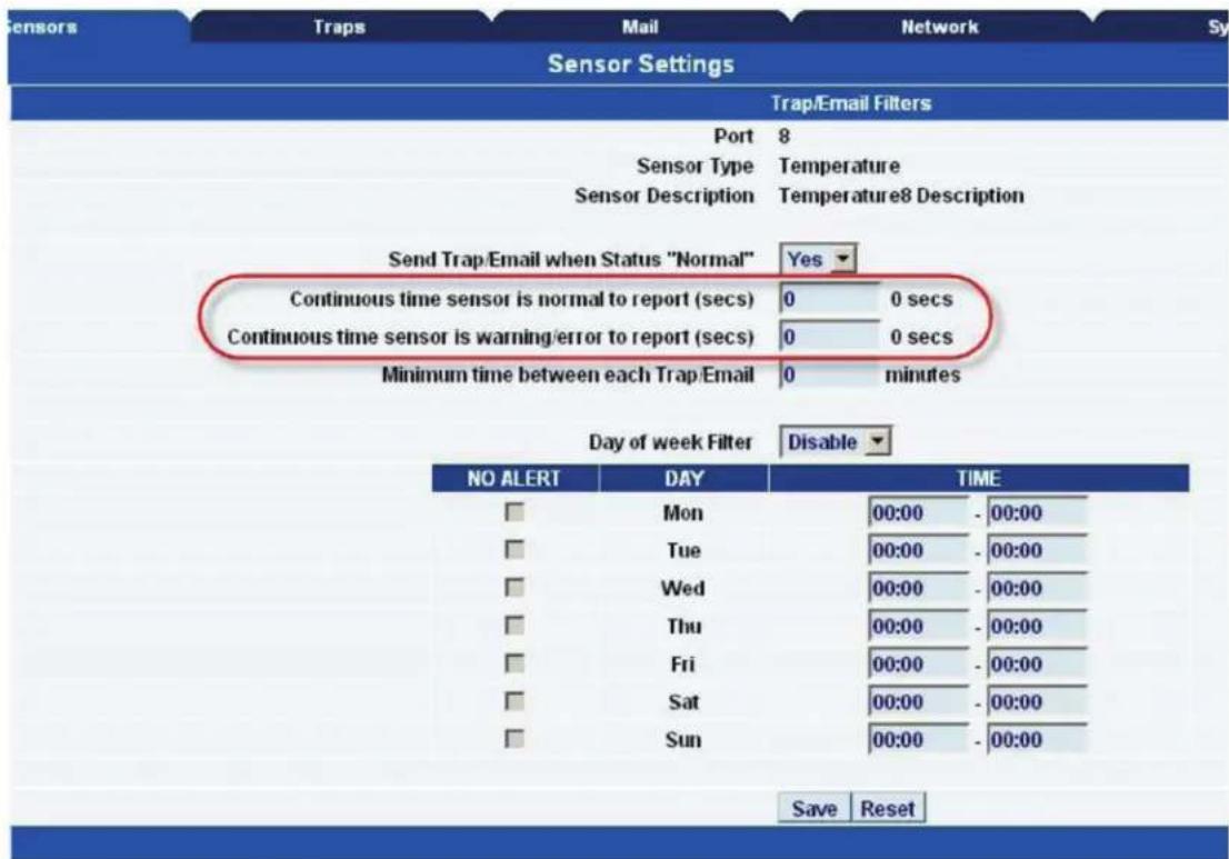
Figure 4-4. Sensor settings screen.
Sensor Status Filters—By clicking on the "Sensors Status Filters" button shown in the image in Figure 4-3, you can then adjust the continuous time the sensor is in a warning, error, or normal state before the unit sends the alerts (see Figure 4-4). This feature was added to eliminate false warnings.
4.2 Downloading Sensor Data
The ServSensor's hardware has data logger memory where it stores the sensor data.
It can save 8,640 points per sensor. So, if you set your collection time period for 15 minutes, you can save roughly up to 3 months of data on the unit. When the memory is full, the oldest data will be overwritten.
There are a couple of ways to download the sensor data from the ServSensors. The first is using the dataCollect or dataDownload utilities. You can download either utility from your support page on our Web site after adding your ServSensor to your product listing.
When running these utilities, make sure your network firewall is not blocking the port that these run on.
The first is called dataDownload, which is a command-line program that will download all the sensor readings stored on the ServSensor. This downloaded data is stored in a text file and can then be easily imported into a spreadsheet program, such as Microsoft® Excel®.
After running this utility, the data will be stored in a directory called datadownload, located on the C: drive of your PC and this will have the data for each port in it.
Or, you can use our dataCollect utility that allows you to poll the sensor data directly from a PC on the same LAN as your ServSensor in real-time. You can collect an unlimited number of readings, and you can collect data from multiple ServSensors simultaneously.
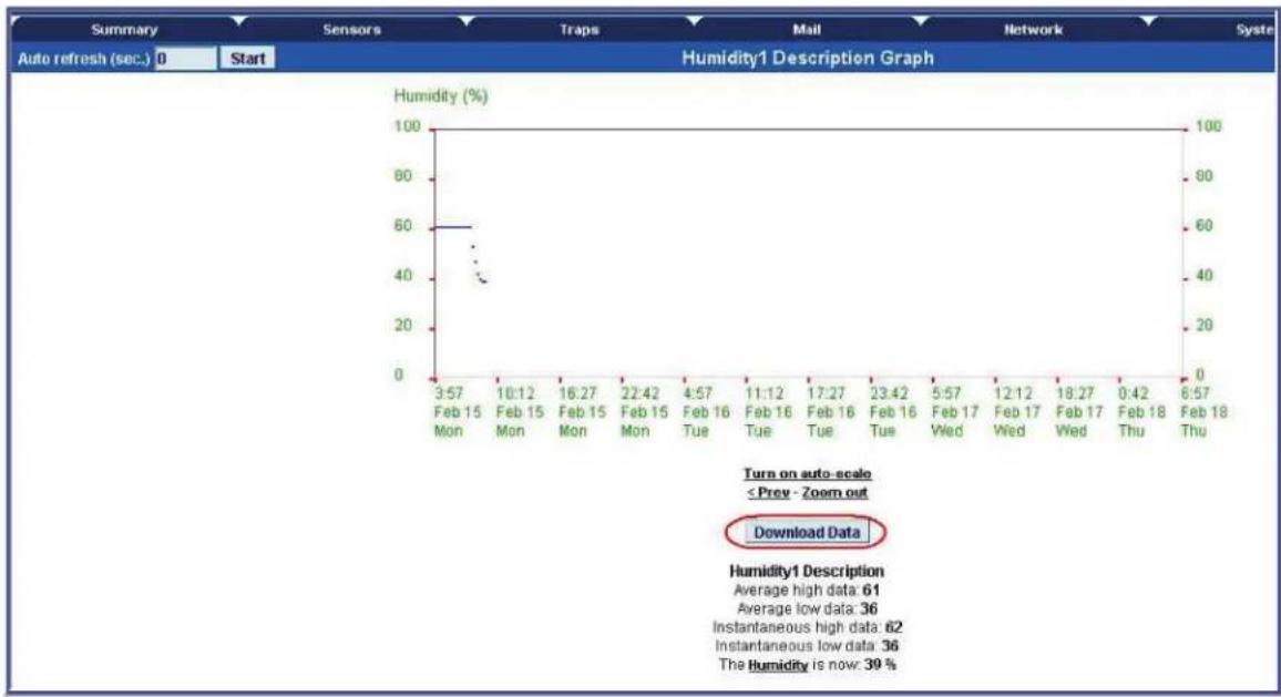
line
| Date | Humidity (%) | | ---------- | ------------ | | 3:57 Feb 15 | 60 | | 10:12 Feb 15 | 40 | | 16:27 Feb 15 | 40 | | 22:42 Feb 15 | 40 | | 4:57 Feb 16 | 40 | | 11:12 Feb 16 | 40 | | 17:27 Feb 16 | 40 | | 23:42 Feb 16 | 40 | | 5:57 Feb 17 | 40 | | 12:12 Feb 17 | 40 | | 18:27 Feb 17 | 40 | | 0:42 Feb 18 | 40 | | 6:57 Feb 18 | 40 |Figure 4-5. Download Data screen.
Using remote syslog to download sensor data
Another way to get and log all the data in real time from the unit is to use the remote syslog on the unit.
You can use the remote system log feature to push out the syslog in real time to a remote server, or PC, then this information can be imported into a data base or other program.
There are two types of third-party remote syslog utilities that we recommend. One is "rsyslog" and the other "Kiwi" remote syslog.
There is no Microsoft Windows ^® version of rsyslog, and there is no GNU ^® Linux ^® version of Kiw ^® .
So, we recommend rsyslog for the GNU Linux users and the Kiwi for the users of the Microsoft operating systems.
Either can be downloaded from these links below:
http://www.rsyslog.com
http://www.kiwisyslog.com/kiwi-syslog-daemon-download/
You can install and open the Kiwi Syslog program and set the UDP in the Input settings (see Figure 4-6).
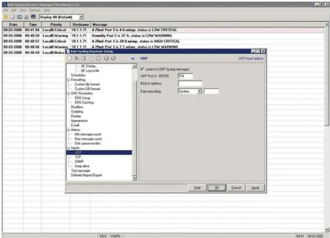
Figure 4-6. Set UDP.
Set the remote syslog in the ServSensor. The remote syslog IP address is the IP address of the PC that has the Kiwi remote syslog program running on it. The remote syslog port is the same port on the remote syslog program.
It should be showing you the syslog in real time, and any entry that is logged in the unit should appear on your server. You can also export the data to a text file.
5. Notifications
5.1 Setting Up a Trap
The ServSensor can send an SNMP trap message to two different hosts. Whenever the status changes for a sensor that is on-line, a trap message can be sent.
To get to the entry point of this tutorial, complete the following:
- Log into the Web interface as administrator.
-
From the summary page select the "Traps" tab.
-
After going to the "traps" tab you can see the two traps ("Trap 1," "Trap 2").
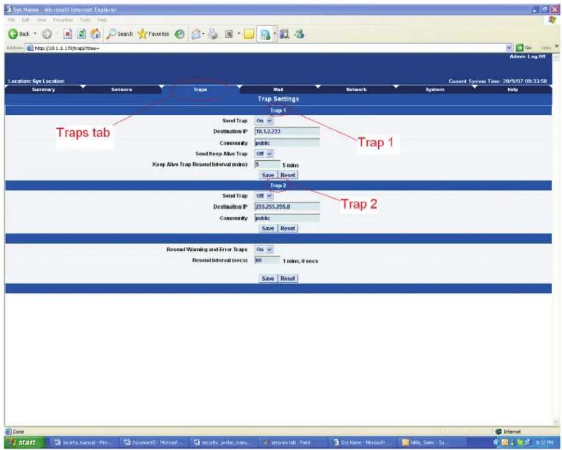
Figure 5-1. Traps screen.
- The traps have various fields you need to set. These are explained next.
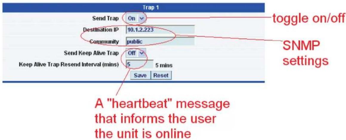
Figure 5-2. Trap 1 screen.
Send Trap—Toggles whether the SNMP trap is on or off.
Destination IP—The destination IP address that the trap message will be sent to.
Community—This is the community of the host that will receive this trap. This is often set to "public."
Send Keep Alive Trap—Will send a trap message at your preset time interval. Use this to inform the user whether the unit is still on-line. You can also use this if you require data collection at regular intervals regardless of the sensor's status.
Keep Alive Resend Intervals—The time interval in which you want the keep alive traps to be sent.
A different trap message is sent for each sensor type such as temperature, humidity, and switch. The trap messages fields include the current sensor status (Normal, Critical High, Warning High, Critical Low, Warning Low, and sensorError), the current sensor value, the level exceeded, the sensor index, the sensor name, and the sensor description.
5.2 Setting Up E-mail Notifications
You can also use SNMP traps to send an e-mail report to notify you of a sensor's status.
To get to the entry point of this tutorial do the following:
- Point your browser to the IP address of your unit.
- Log in as "administrator."
- Click the "Mail" tab from the summary page.
- This brings you to a new page. From here you can setup the various e-mail parameters.
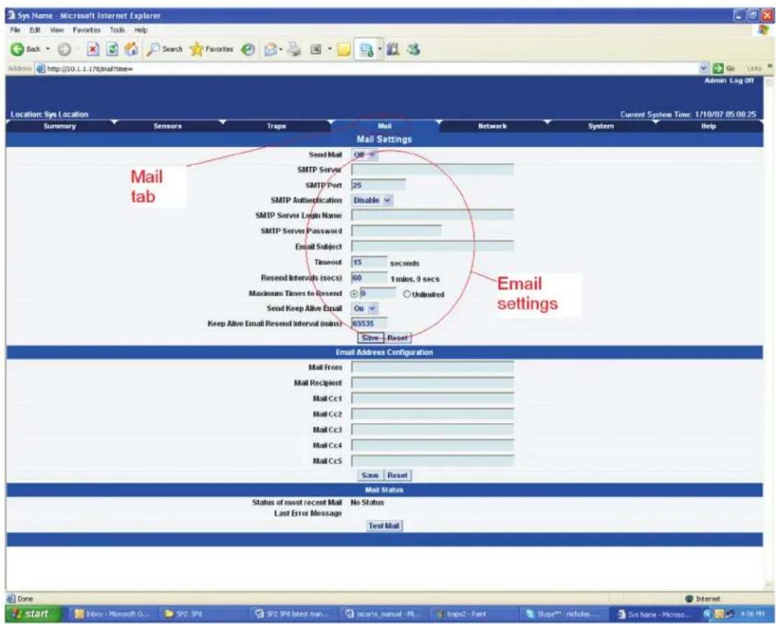
Figure 5-3. Mail Parameters Setup screen.
- You can now set up the individual e-mail options from the fields shown next.
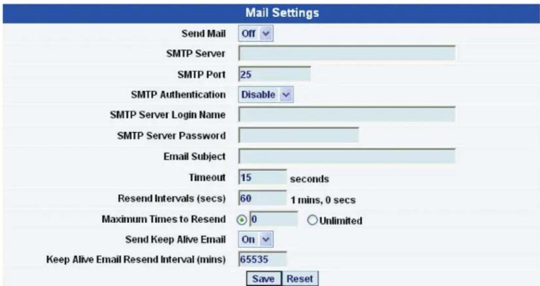
Figure 5-4. Mail Settings screen.
Send Mail—This toggles the send e-mail option on or off.
SMTP Server—The address of your SMTP server.
SMTP Authentication—Check this option if your SMTP server requires authentication.
SMTP Server Login Name—The user name to log in to your SMTP server.
SMTP Server Password—The password used to log in to your SMTP server.
E-mail subject—The subject you want to have for the e-mail. For example, "ServSensor notification."
Timeout—You can increase the timeout for SMTP servers that have poor connectivity. It is best to leave this number as low as possible while still allowing for communication with the SMTP server to continue.
Resend Intervals—The time between which the e-mails will be sent.
Maximum Times To Resend—Set the number of times you want the notification e-mails to be resent.
Send Keep Alive Email—This option will tell the unit to send a heartbeat e-mail. Use this to tell if the unit is still on-line or not. You can also use this when you require data collection at regular intervals.
Keep Alive Email Resend Interval—The amount of time between which the keep alive emails are sent.
-
After setting your parameters, click the "Save" button.
-
Below this, you will see there is another section. Use this to configure the e-mails' recipients.
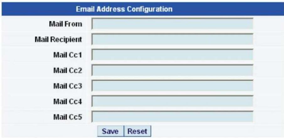
Figure 5-5. E-mail Address Configuration screen.
Mail From—The e-mail address that you want the e-mail to appear from. Because of anti-spam features of some SMTP servers, this address must be authorized on the SMTP server; otherwise, the server may deny the email.
Mail Recipient—The email address of the person you want to send the email to.
Mail Cc1-5—Up to five additional e-mail addresses may be added.
8. When you have filled in your required fields, remember to click "Save."
9. At the bottom of the page you have two further options.
| Mail Status | |
| Status of most recent Mail | No Status |
| Last Error Message | |
| Test Mail | |
Figure 5-6. Mail status options.
Status of most recent Mail—This can be either "No Status," "Success," or "Failure."
Last Error Message—This is a debugging aid. If the e-mail is not successfully sent, you may find the reason for the problem here.
Test E-mail—Use this when you first set up the SMTP settings to make sure they are working, or anytime thereafter. Before a test mail can be generated, make sure the previous fields described have been completed.
NOTE: If you having problems connecting to your SMTP e-mail server, go to Chapter 8.
6. System Settings
6.1 Network Settings
The Network Settings page allows you to change network settings, such as the IP address etc., for your unit.
To get to the entry point of this tutorial, complete the following:
- Point your Web browser to the IP address of your unit.
- Log in as administrator.
- From the "Settings" page, select the "Network" tab.
NOTE: You can change your default HTTP port on the unit using this SNMP set command:
You can still use Port 80 for Web access as well.
- After clicking the "Network" tab you will be taken to the screen shown in Figure 6-1.
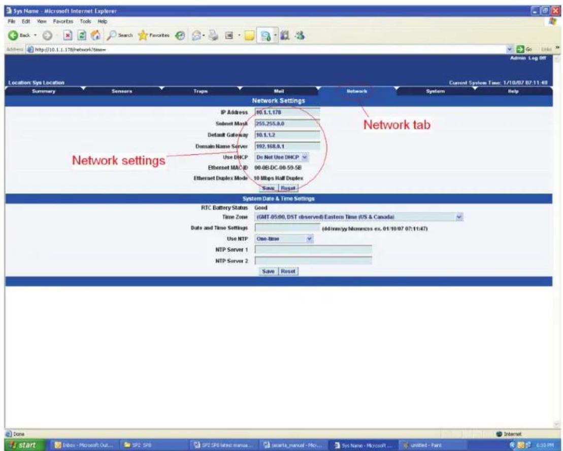
Figure 6-1. Network screen.
- Once on this page, you can set up the network settings as indicated below:
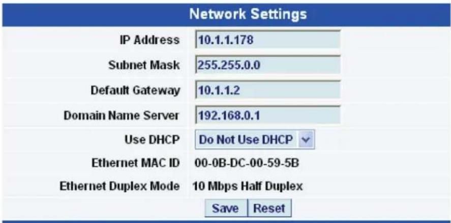
Figure 6-2. Network Settings screen.
IP Address—Use this to change the IP address of your unit.
Subnet Mask—Use this to assign the subnet mask of your unit.
Default Gateway—Assign the default gateway of your device.
Domain Name Server—IP address of your DNS. This enables you to use a DNS address for your unit instead of accessing it via the IP address.
Use DHCP—The unit can use DHCP to assign its IP address, or it can use a statically assigned IP address. To use DHCP, choose "Use DHCP" from the list box and press "Set." To stop using DHCP, choose "Do Not Use DHCP" from the list box and press "Set." Statically assigning an IP address also turns off DHCP. You can force the ServSensor to voluntarily give up its IP lease and request a new IP lease by choosing Use DHCP from the list box and pressing "Set."
Ethernet MAC ID—This is the MAC address of your unit. It is a read-only field.
Ethernet Duplex Mode—The duplex mode and speed of your unit. This is also a read-only field.
NOTE: Make sure you apply your new settings by clicking on the "Save" button.
- Below this, there are some further settings for the time and date.
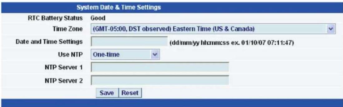
Figure 6-3. System Date and Time Settings screen.
RTC Battery Status—This field displays the status of the real-time clock battery on the unit. If the status displays "Bad," you must replace the battery; otherwise, when the ServSensor does not have power, the clock will stop running. Re-configure the system time settings on every reboot.
Date and Time Settings—Enter the new date and time in this field. The date and time use the following format: date/month/year (dd/mm/yy) and hour:minute:second (hh:mm:ss).
Time Zone—Select the time zone for your location from this list box.
Use NTP—A Network Time Protocol (NTP) is used to sync your units clock over a network. There are many options in this list box. The details for each one are as follows:
- Do Not Use NTP—Select this option to turn off the time synchronization feature.
- One Time—The time is synchronized when you press the "Save" button.
- On System Start Up—The time is synchronized once the hub is turned on or rebooted.
- Once a Month/Week/Day/Hour—The time is automatically synchronized every month, week, day, or hour, respectively.
NTP Server 1 and 2—Set the IP address of the NTP servers to be used. The NTP will synchronize the time with the server that has the lowest number.
6.2 System Tab
From the system tab, you can input various settings for the unit. These settings are mostly optional.
To get to the entry point of this tutorial, complete the following:
- Point your browser to the unit's IP address.
- Log in as administrator using your admin password.
-
From the summary page, click on the "System" tab.
-
When you arrive at the Settings page, you will see the following screen:
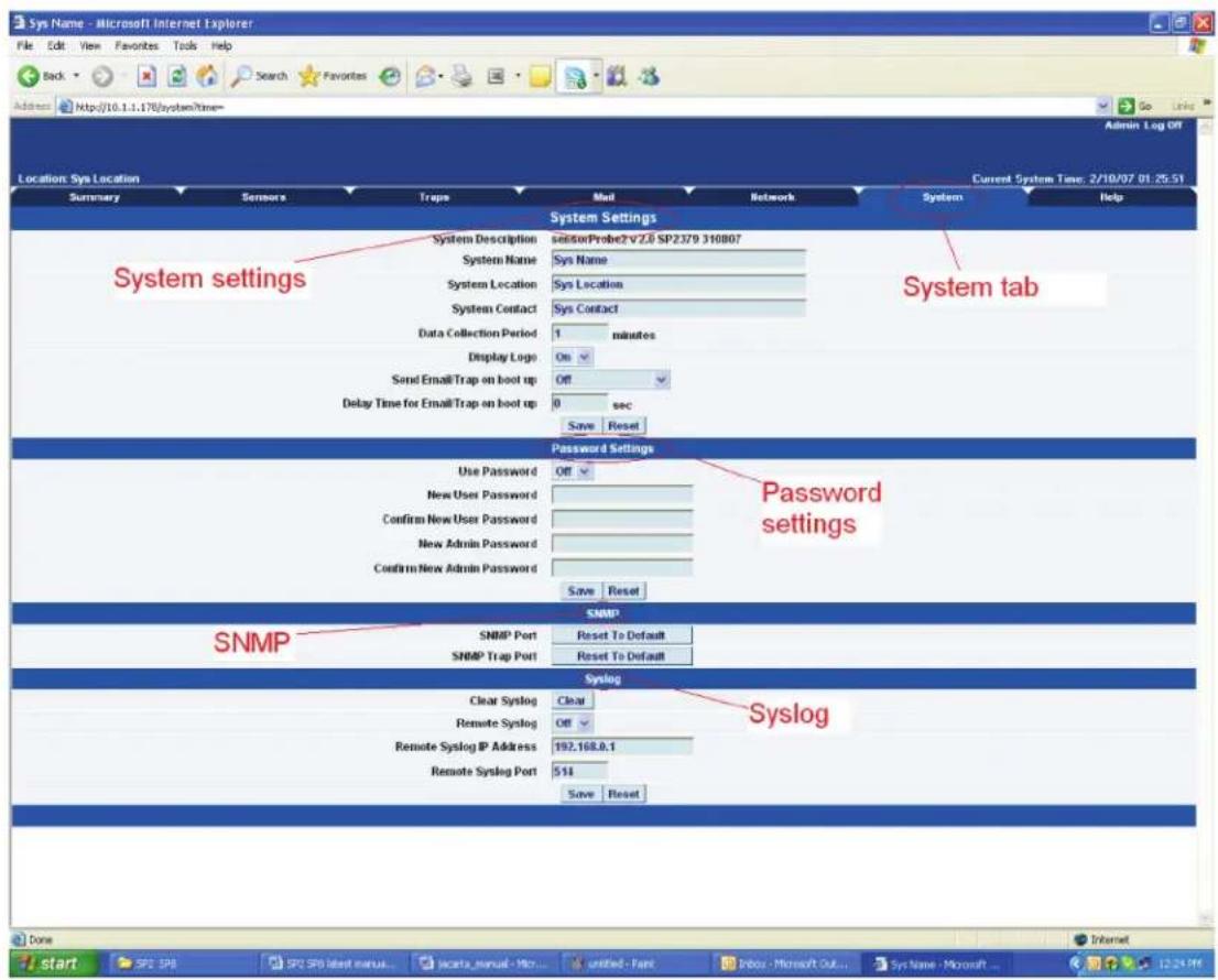
Figure 6-4. Settings screen.
- The first section is entitled "System Settings."
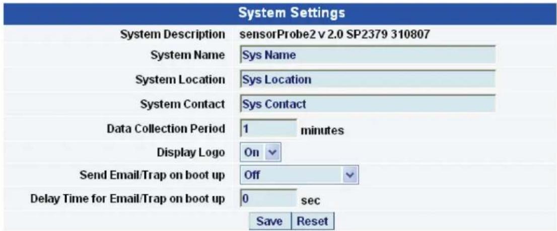
Figure 6-5. System Settings screen.
System Description—This is an MIB II value set when the microcode for the unit was installed. It includes the build time and version of the microcode. This is a read-only field.
System Name/Location/Contact—These are used to identify the system. They are accessed via standard SNMP utilities. The SNMP utilities use these to get information about the unit.
Data Collection Period—This controls how often data is collected for use in the graph function.
Display Logo—Turn off displaying the logo by using this option. This option can be turned off to enable the Web pages to load faster.
Send Email/Trap on boot up—Use this option to send an e-mail and SNMP trap each time the system boots up.
Delay Time for Email/Trap on boot up—The time in seconds to delay before sending the bootup e-mail or trap.
NOTE: Remember to click the "Save" button after making any changes.
- The next section is used for setting a user password, or changing the admin password.
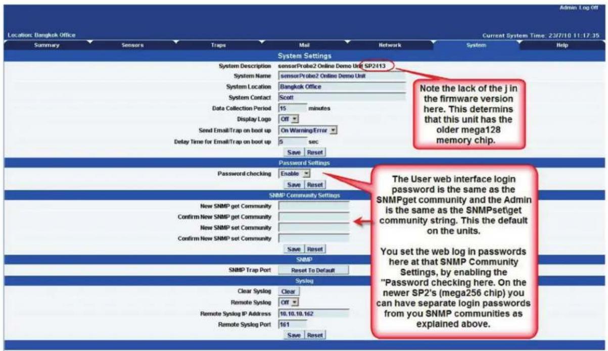
Figure 6-6. Set the password.
Depending on which version of ServSensor Jr. you have, your System page may appear different. The ServSensor Jr. units that were shipped before October 2009 have the older memory mega128 chip. If this is the case, your screen will appear like the screens shown in Figures 6-5 and 6-6. This System page will also show in the ServSensor 8 interface on units shipped before July 1, 2011. For current screen explanations, contact Black Box Technical Support at 724-746-5500 or info@blackbox.com.
NOTE: To allow the user to log in without having to enter a password, use "public" in the SNMP get.
The user Web interface login password is the same as the SNMPget community, and the Admin is the same as the SNMPset\get community string. You set your Web interface login passwords in the SNMP community settings by enabling the "Password checking" above, then entering your passwords into these fields.
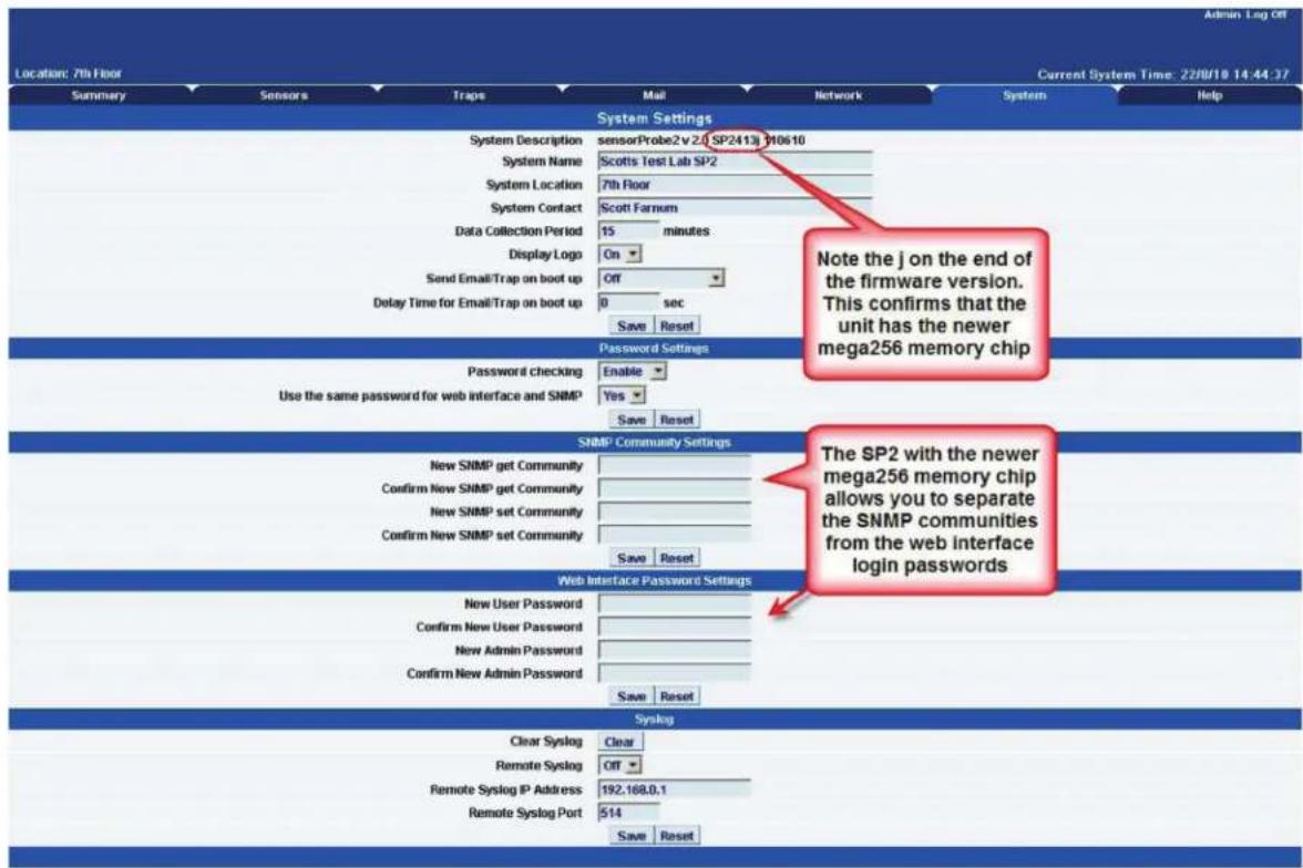
Figure 6-7. Setting SNMP passwords.
NOTE: The "j" on the end of the firmware version above confirms that the unit has the newer mega256 memory chip. The ServSensor with the newer mega256 memory chip allows you to separate the SNMP communities from the Web interface login passwords.
Password Checking—Toggle whether the password is required or not.
Use the same password for the Web interface and SNMP—Ties the SNMP communities to the Web interface login passwords.
New User Password—Type in the password for the user account.
NOTE: To allow the user to log in without having to enter a password, type in "public" for the user password.
Confirm New User Password—Confirm the new password for the user account.
New Admin Password—Type in the password you want to use for the admin account.
Confirm New Admin Password—Confirm the new password for the admin account.
- Next, you have the options for resetting the SNMP trap settings.

Figure 6-8. SNMP Trap Settings screen.
SNMP Port—Use this option to reset the SNMP port setting to its default.
SNMP Trap Port—Use this option to reset the SNMP trap port to its default setting.
NOTE: Your SNMP port default is 161 and the SNMP trap port default is 162. You can set your SNMP ports with the following commands:
snmpset -m all -v 1 -c <community> <ipaddress>.1.3.6.1.4.1.3854.1.2.2.1.99.0 u <new snmp port>
snmpset -m all -v 1 c <community> <ipaddress>.1.3.6.1.4.1.3854.1.2.2.1.100.0 u <new snmp trap port>
- Finally, you have the option for setting up the system log parameters.
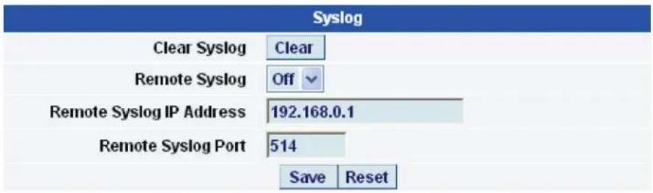
Figure 6-9. System Log Parameters Settings screen.
Clear Syslog—Used to clear the system log of the messages for the unit.
Remote Syslog—You can set up the unit to send its syslog message in a standard format acceptable to a remote syslog server. For example, the Logalot system from Somix®.
Remote Syslog IP Address, Remote Syslog Port—You can set the IP address and port of the remote syslog server to where the unit will send the log messages. Contact Technical Support at 724-746-5500 or info@blackbox.com for details.
7. Making Your Unit Visible to the Internet
So far the manual has simply covered the basic setup. The setup we have just created will allow you to access your unit on a Local Area Network (LAN). We have setup SNMP traps so that your SNMP software, such as Whatsup Gold or HPOpenView ^® can collate information from your unit.
However, you might want to remotely access your unit from anywhere in the world. This is possible; however, the following steps are only an outline guide. Your exact setup and configuration will often depend on your network equipment and setup. You are going to need access to your router if you are using one, and knowledge of whether your IP address is static or dynamic.
7.1 Simple Setup
- Let's imagine that your unit is connected to a router on your network, and the following IP addresses are assigned:
Your unit's IP address is the default 192.168.0.100.
Your computer's IP address is 192.168.0.200.
Your router's IP address is 192.168.0.300.
- To find out your router's external IP address, go to www.whatsmyip.com.
Let's imagine your router's external IP address is 278.67.04.09.
- You now need to set up port forwarding on your router. This varies depending on your router's model. Generally, you need to point your browser to your router's IP address (in this case 192.168.0.300). This will then allow you to log into your routers administration interface. You can find how to do this for your router on www.portforward.com. For an example of how to do this for a commonly used router, follow this link:
http://www.portforward.com/english/routers/port_forwarding/Linksys/WRT54G/HTTP.htm
You need to set up your router's HTTP forwarding to Port 80. This will then mean when you access your router using the external IP address, you will be forwarded to your unit's internal IP address.
-
To test this, open your Web browser, and go to your external IP address (in our example, 278.67.04.09). If you're using a dynamic IP address, check it again before doing this because it may have changed since the start of this tutorial.
-
To make this easier, you could use a dynamic DNS (Dynamic Name Server). This means you no longer need to remember IP addresses or use www.whatsmyip.com to find your IP address. You will instead register a domain name (for example myServSensor2.homeip.com). This will then automatically point your router's external IP address (for example, 278.67.04.09). This will require you to register the domain name and open an account with a DNS server provider. We recommend www.dyndns.com because they allow up to five free domain names to be registered.
-
If you have set up everything correctly, you can now access your unit from anywhere in the world by simply pointing your Web browser to your DNS address.
7.2 Setting Up Your PC's Routing Table
To set up the routing table, open a DOS window (Start, Run type command, press Enter) and at the command prompt type in:
route add 192.168.0.10 0 10.1.1.20
8. Frequently Asked Questions (FAQs)
Question: How does the ServSensor record the sensor data and how much can it store?
Answer: The ServSensor will record and store the changes for the dry contacts and sensors because the unit's hardware has a data logger where it stores this data in memory. It can save 8,640 points per sensor. So, if you set your collection time period for 15 minutes, for example, then you can save data up to 3 months on the unit.
Question: Can you please tell how often the ServSensor unit interrogates each sensor to obtain the sensor's readings?
Answer: This really depends on the sensor type that you have connected to the unit. The switch-type sensor interrogates with the ServSensors more than 2 times per second. The temperature and analog type sensors interrogate 1 time per second. But all of the readings depend on the environment like the number of sensors you have on-line and your e-mail and SNMP trap alert settings.
Question: Is there a way to reboot the ServSensor unit's Web interface remotely?
Answer: Yes, you can reboot the unit's Web interface remotely using this SNMP command and OID here:
Question: Is there any way to edit the content of the e-mail alerts that are sent out from my ServSensor unit?
Answer: Yes, we have added a separate e-mail notification function. You can set this by using the following SNMP command:
When
Question: I have forgotten the IP address that my ServSensor is configured with. Is there a way I can determine this IP?
Answer: Yes, you can unplug the power cord, then plug it back in, to cycle the power on the ServSensor while you have the IPSet utility software running on your PC. When you open the IPSet utility, it will say "Recycle power to ServSensor" (as shown in Figure 8-1).
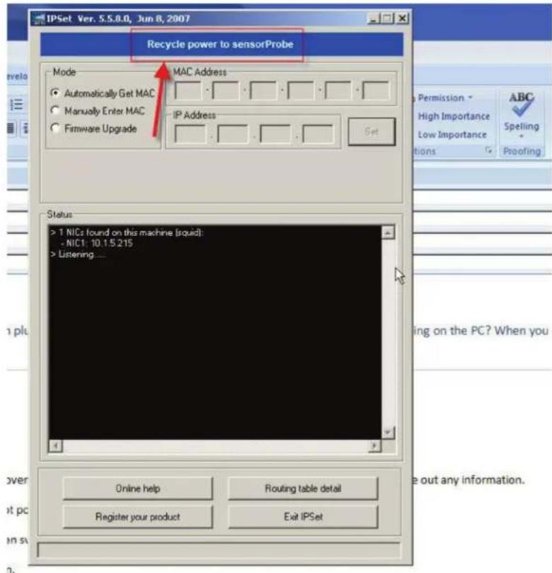
Figure 8-1. Finding the ServSensor's IP address.
When the ServSensor is powered up, the IPSet will capture its IP address, then you will be able to click on the flashing button to open the Web interface. You can download the IPSet utility by logging into the Black Box Web site (www.blackbox.com) with your unit's MAC ID.
Question: Is there a way to reset my unit back to the factory default settings?
Answer: Yes, you can reset the unit back to the factory default settings using our utility called "Configure." You can download this from our Web site. When you reset the unit, keep it directly connected to your PC with the cross-connect cable. Once you reset the unit, run the latest firmware update as well with the utility. You can download this from the same link above.
Question: I am still having trouble connecting to the unit and opening the Web interface. What could be the problem and what should I try?
Answer: If you are using Internet Explorer ^® 7 or 8 Web browser versions, try placing the unit in the "trusted sites" list. Try clearing the cache and refreshing your browser with the Ctrl + F5 key. Are you using HTTPS? The ServSensors and IPSet do not support HTTPS. This is only available on the ServSensor V4E Hub units.
Question: I have assigned the gateway IP, and when I click "Save," it reverts back to the default IP. What should I do?
Answer: This happens when the device can't find the IP entered. When the IP is entered, the device searches for the IP and will accept it if it is found, or else it will revert back to the default IP.
Question: I have an alert condition from one of my sensors attached to my ServSensor unit: the base unit started to send e-mail alerts. Before I was able to fix the problem, my SMTP server was clogged with several hundreds of messages waiting in the outbound queue to be sent. Is there a way to add a parameter to the base unit's Web interface that defines the interval between successive e-mail alerts to limit the rate at which these alerts are being sent and keep the SMTP server operational?
Answer: Yes, we have the "Minimum time between each Trap/Email" feature in the Sensor Settings > Sensor Status Filters button. This feature can limit the traps and e-mails that the unit will send. A similar parameter also exists on the ServSensor's web interface called "Resend Intervals (secs)" and another one called "Maximum Times to Resend" will also limit the alerts being sent.
Question: I am having trouble connecting the ServSensor to my SMTP e-mail server, what could be the problem?
Answer: Here are some things to check when having trouble with SMTP server connections and saving your settings.
- Try changing your SMTP server from the name to the IP address of the server.
- The SMTP server is entered is wrong.
- The send mail option is not enabled in the Mail settings page.
- The timeout period entered is too low.
- The gateway IP is not entered in the network page.
- The mail from address is not set.
- The mail server is not responding.
- The mail from address is not validated in the mail server.
- The mail server settings prohibit it from accepting connections from the device IP.
- The mail server is an SSL type, which is not supported by the ServSensor units.
Question: I am using Microsoft® Exchange Server, but the Exchange server fails to receive the e-mail alerts from my ServSensor unit. Does my ServSensor support MS Exchange Server?
Answer: Yes, the units do support MS Exchange Server. However, the ServSensors only support basic authentication. MS Exchange, by default, when a connector is set up uses TLS, then basic. You have to uncheck this option.
Question: Is there a way to download my sensor data, or push this out in real time to my PC?
Answer: Yes, you have several options for collecting, downloading, and storing the data from the ServSensor units. See Section 4.2.
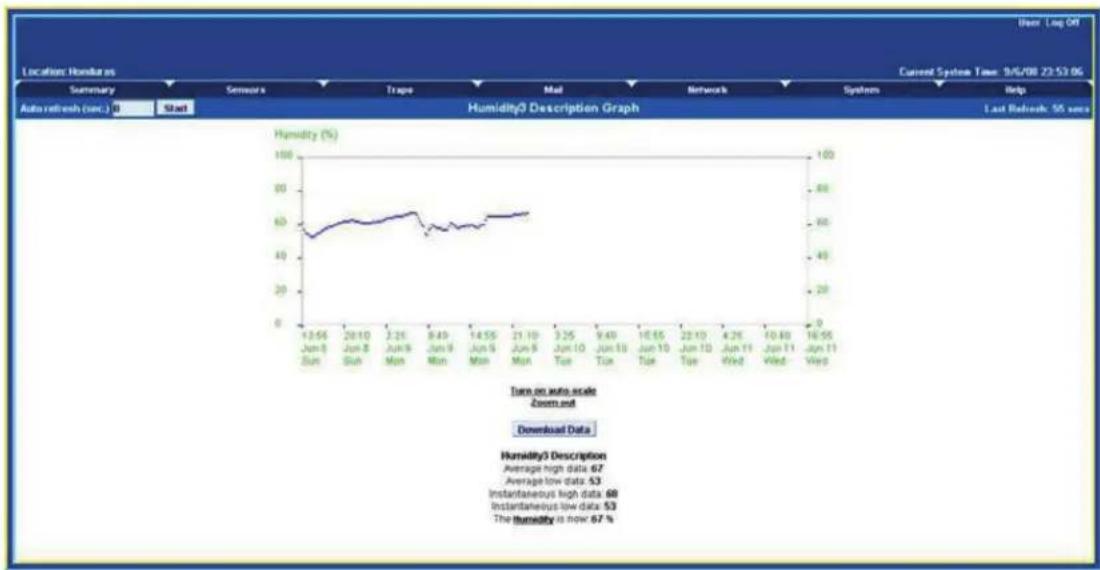
You can graph each sensor's output readings and then download that data as a text file, so you can import it into, for example, an Excel spreadsheet. Click on the Graph >> View in the Summary screen and a screen similar to Figure 8-2 will appear.
line
| Date | Humidity (%) | | ---------- | ------------ | | 12.56 | 50 | | 20.10 | 60 | | 2.26 | 65 | | 9.40 | 55 | | 14.55 | 60 | | 21.10 | 65 | | 3.25 | 60 | | 9.40 | 65 | | 16.55 | 60 | | 22.10 | 65 | | 4.25 | 60 | | 10.40 | 65 | | 16.55 | 60 |Figure 8-2. Output readings graph.
We also have two utilities that allow you to download the sensor data. The first is called dataDownload, which is a command-line program that will download all the sensor readings stored on the ServSensor. This data is then stored in a text file and can then be easily imported into a spreadsheet program, such as Microsoft Excel. Contact Black Box Technical Support at 724-746-5500 or info@blackbox.com for details.
Or, you can use our dataCollect utility that enables you to poll the sensor data directly from a PC on the same LAN as your ServSensor in real time. You can collect an unlimited number of readings and you can collect data from multiple ServSensors simultaneously. You can download this from the Black Box Web site by first logging in with your unit's MAC ID.
Question: I am not too familiar with SNMP or what Object Identifiers (OIDs) to use with your products. How would I find out more about this and what OIDs to use?
Answer: Contact Black Box Technical Support at 724-746-5500 or info@blackbox.com.
Black Box Tech Support: FREE! Live. 24/7.
Tech support the way it should be.

natural_image
Close-up portrait of a smiling man with short hair, hand near ear (no text or symbols visible)Great tech support is just 30 seconds away at 724-746-5500 or blackbox.com.

BLACK BOX®
NETWORK SERVICES
About Black Box
Black Box provides an extensive range of networking and infrastructure products. You'll find everything from cabinets and racks and power and surge protection products to media converters and Ethernet switches all supported by free, live 24/7 Tech support available in 30 seconds or less.
© Copyright 2012. Black Box Corporation. All rights reserved.
EME102A-R2, version 1
- AlertWerks™ ServSensor Jr. and ServSensors
- Monitor environmental variations, power, physical threats, and security.
- Trademarks Used in this Manual
- Federal Communications Commission and Industry Canada Radio Frequency Interference Statements
- Specifications
- Overview
- Introduction
- What is the AlertWerks ServSensor?
- Available Models
- How to Use this Manual
- Features
- What's Included
- EME102A-R2:
- EME103A-R2:
- EME104A-R2:
- EME152A:
- EME153A:
- EME154A:
- EME108A-R2:
- EME109A-R2:
- EME110A-R2:
- EME111A-20-R2:
- EME111A-60-R2:
- EME112A-20-R2:
- EME112A-60-R2:
- EME113A-20-R2:
- EME113A-60-R2:
- Hardware Description
- ServSensor Jr. (EME102A-R2, EME103A-R2, EME104A-R2, EME152A, EME153A, EME154A)
- ServSensor 4 (EME105A, EME106A, EME155A)
- ServSensor 8 (EME108A-R2, EME109A-R2, EME110A-R2. EME158A)
- ServSensor X20 (EME111A-20-R2, EME111A-60-R2, EME112A-20-R2, EME112A-60-R2, EME113A-20-R2, EME113A-60-R2)
- ServSensor 8-X20 20 Extra Dry Contact Inputs
- Extra dry contact input practical applications:
- Installation
- Assigning an IP Address
- Testing your New IP Address
- Having connection problems?
- Upgrading the Firmware
- Setting up a Sensor and Downloading Sensor Data
- Basic Setup
- Downloading Sensor Data
- Using remote syslog to download sensor data
- Notifications
- Setting Up a Trap
- Setting Up E-mail Notifications
- System Settings
- Network Settings
- System Tab
- Making Your Unit Visible to the Internet
- Simple Setup
- Setting Up Your PC's Routing Table
- Frequently Asked Questions (FAQs)
- Black Box Tech Support: FREE! Live. 24/7.
- BLACK BOX®
- NETWORK SERVICES
- About Black Box
Brand : Black Box
Model : AlertWerks EME155A
Category : Uncategorized