
SPK811W - Speaker stand Peerless-AV - Free user manual and instructions
Find the device manual for free SPK811W Peerless-AV in PDF.

| Product Type | Speaker Stand |
| Brand | Peerless-AV |
| Model | SPK811W |
| Compatible Speaker Size | Bookshelf speakers up to 20 lbs (9 kg) |
| Height (Adjustable) | 24 to 36 inches (61 to 91 cm) |
| Top Plate Dimensions | 6 x 9 inches (15.2 x 22.9 cm) |
| Base Dimensions | 10 x 12 inches (25.4 x 30.5 cm) |
| Weight Capacity | 20 lbs (9 kg) per stand |
| Weight (Each) | 5.5 lbs (2.5 kg) |
| Material | Heavy-duty steel with powder coat finish |
| Color | Black (standard) |
| Adjustment Type | Two-piece locking post with screw collar |
| Included Hardware | Speaker mounting screws, base spikes, carpet spikes, rubber feet |
| Base Fillable | Yes, can be filled with sand or shot for stability |
| Assembly Required | Yes, simple assembly with included Allen key |
| Warranty | 5-year limited warranty |
| Cable Management | Internal channel for speaker wire routing |
| Surface Protection | Non-marring rubber base pads included |
| Package Contents | 2 stands, hardware pack, Allen key, user manual |
| Country of Origin | China |
Frequently Asked Questions - SPK811W Peerless-AV
User questions about SPK811W Peerless-AV
0 question about this device. Answer the ones you know or ask your own.
Ask a new question about this device
Download the instructions for your Speaker stand in PDF format for free! Find your manual SPK811W - Peerless-AV and take your electronic device back in hand. On this page are published all the documents necessary for the use of your device. SPK811W by Peerless-AV.
USER MANUAL SPK811W Peerless-AV
Assembly Instructions - Universal Speaker Mounts
IMPORTANT! Read entire instruction sheet before you start installation and assembly.
For customer service, call 1-800-729-0307 or 708-865-8870.
Models:
SPK 811, SPK 811W
MAXIMUM LOAD CAPACITY:
20 lb (9 kg) each mount.
Tools Required: Drill,
screwdriver, two 7/16"
open end wrenches,
channel locks, hammer,
pencil, tape measure, level.
Parts List
| Description | Qty. | SPK 811 | SPK 811W |
| A mounting base | 1 | 590-1144 | 590-2144 |
| B extension | 1 | 590-1145 | 590-2145 |
| C cap | 1 | 590-1146 | 590-2146 |
| D ball | 1 | 590-1147 | 590-2147 |
| E M4 x .7 x 10 mm phillips screw | 4 | 504-9012 | 520-2027 |
| F M5 x .8 x 8 mm phillips screw | 4 | 570-0005 | 520-9530 |
| G M6 x 1 x 10 mm phillips screw | 4 | 520-9401 | 520-9524 |
| H 1/4-20 x 1/2 phillips screw | 4 | 510-9108 | 520-9511 |
| I 10-32 x .313 phillips screw | 2 | 520-1173 | 520-2173 |
| J #10 x 3/4 phillips wood screw | 4 | 500-9006 | 500-2014 |
| K 1/4-20 serrated locknut | 2 | 530-1021 | 530-2021 |
| L #10 flat washer | 2 | 540-9400 | 540-9442 |
| M 1/4-20 keyhole adapter | 1 | 580-1026 | 580-2026 |
| N 1/4-20 to M5 reducer | 1 | 580-1027 | 580-2027 |
| O 1/4-20 to M4 reducer | 1 | 580-1028 | 580-2028 |
| P 1/4-20 coupling | 1 | 580-1029 | 580-2029 |
| Q mounting plate | 1 | 087-1037 | 087-2037 |
| R toggler | 2 | 560-9717 | 560-9717 |
| S #10-24 x 2" phillips screw | 2 | 520-2078 | 520-2078 |
| T plastic #10 screw plug | 2 | 590-1158 | 590-2158 |
| U concrete anchor | 2 | 590-0097 | 590-0097 |
| V #10 x 1 1/2" wood screw | 2 | 510-9163 | 500-2002 |
| W M4 KEPS hex nut | 2 | 530-1041 | 530-2041 |
| X M4 serrated washer | 2 | 540-1033 | 540-2033 |
| Y M4 x 16 mm socket pin screw | 2 | 510-1087 | 510-2087 |
A B C


D

K

M

N

O

P

R

L

Q

|

J

E

F

G

H

S


natural_image
Two simple line drawings of cylindrical containers, one with a lid and the other with a hole (no text or symbols)U

V

W

X

Y

If you are missing a fastener, please contact our customer service department before returning the speaker mounts to store from which they were purchased.

Attachment of Base Unit to Wall or Ceiling
Note: Ceiling applications must be mounted to a ceiling joist (NO Drywall Only). Extension column will be used mostly with ceiling applications.
If bringing wire in from behind wall, make sure that wires are run through wire management slot * before mounting base unit (A) to wall or ceiling.

When using extension column, be sure to mount base unit (A) with wire management slot facing right so that wire management hole in extension (B) * is facing down. Remember to run wires through wire management hole before mounting base unit (A) to wall or ceiling.


For Attachment to Wood Stud Walls: Use a stud finder to locate center of stud. Drill two 3/16" (5 mm) dia. holes to a minimum depth of 2" (51 mm). Attach mounting base unit (A) to center of wood stud using two wood screws (V) and two plastic screw plugs (T) as shown left.
IMPORTANT: Make sure wall bracket is level on wall.

For Attachment to Metal Stud Walls or Direct Attachment to Drywall for Speakers Over 10 lb: Use a stud finder to locate center of stud. Drill two 5/8" (16 mm) dia. holes through metal stud. Attach mounting base unit (A) to center of metal stud using two #10-24 phillips screws (S), two plastic screw plugs (T) and two togglers (R) as shown in DETAIL ONE.
IMPORTANT: Make sure mounting base (A) is level on wall. Product must be mounted through drywall that has a minimum thickness of 1/2" and into metal studs, 26 gauge or heavier.
DETAIL ONE

Place screw (S) through bottom of plastic screw plug (T) and mounting base (A). Partially fasten toggler (R) to back of screw. Pivot toggler ends 90° and push through hole in drywall.

Pull screw back until toggler is flush with metal stud and hold. Thread screw through with fingers and tighten securely. Place top of plastic screw plug (T) over screw.
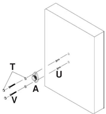
For Attachment to Concrete or Direct Attachment to Drywall for Speakers Under 10 lb: Drill one 1/4" (6 mm) dia. hole to a minimum depth of 2" (51 mm). Insert one anchor (U) in hole flush with wall. Place mounting base unit (A) over anchor (U) and secure with one wood screw (V) and one plastic screw plug (T). Make sure wall bracket is level, mark other hole and repeat steps with other fasteners. Tighten all fasteners.
IMPORTANT: Make sure wall bracket is level on wall.
WARNING
- When installing Peerless wall mounts on cinder block, verify that you have a minimum of 1 5/8" of actual concrete surface in the 1/4" diameter hole to be used for the concrete anchors. It is suggested that a standard electric drill on slow setting is used to drill the hole instead of a hammer drill to avoid breaking out the back of the hole when entering a void or cavity. Do not drill into mortar joints!
- Never attach concrete expansion anchors to concrete covered with plaster, drywall or other finishing material. If mounting to concrete surfaces covered with a finishing surface is unavoidable, the finishing surface must be counterbored.
- Tighten concrete anchor bolt firmly, but do not over-tighten. Overtightening can damage the bolt, greatly reducing its holding power.
- Never tighten in excess of 80 in • Ib (9 N.M.).
Note: If you are unable to attach your speaker to the Universal Speaker Mount please contact our customer service department for assistance prior to returning this product to the store from which it was purchased.

Attachment of Ball and Cap to Speaker
For Attachment to Speakers with a Keyhole on Back: Thread keyhole adapter (M) into coupling (P) a few turns. Insert assembly into keyhole on back of speaker as shown in DETAIL TWO. Hand tighten coupling (P) until it fits tightly against back of speaker. Use 7/16" open end wrench to tighten coupling (P) until it is secured to speaker. Insert ball (D) through cap (C) and thread into coupling (P). Hand tighten ball (D) until it is secured to coupling (P).
For Attachment to Speakers with a Single Threaded Insert: For 1/4-20 size threaded inserts, thread one locknut (K) halfway onto ball (D). Insert ball (D) through cap (C) and thread directly into threaded insert on back of speaker. Tighten locknut (K) until it is securely against back of speaker. For M5 and M4 size threaded inserts, use reducer (N) or (O) to thread ball (D) into threaded insert. Note: Locknut (K) is not used with reducer (N) or (O).


For Attachment to Speakers with More Than One Threaded Insert: Insert ball (D) through cap (C) and attach mounting plate (Q) using two serrated locknuts (K) as shown in DETAIL THREE. Attach mounting plate (Q) to speaker using two or four screws (E), (F), (G), (H) or (I) as needed for speaker threaded insert pattern.

For Speakers with Four Threaded Inserts For Speakers with Two Threaded Inserts


For Attachment to Speakers with Two Keyholes: Insert ball (D) through cap (C) and attach mounting plate (Q) using two serrated locknuts (K) as shown in DETAIL THREE. For each keyhole, slide a M4 serrated washer (X) onto a M4 x 16 mm socket pin screw (Y). Tilt and drop both M4 serrated washer (X) and M4 x 16 mm socket pin screw (Y) into slot on speaker back and slide into locking position. Place bracket mounting plate (Q) onto M4 x 16 mm socket pin screws (Y). Fasten #10 flat washer (L) then M4 KEPS hex nut (W) onto each M4 x 16 mm socket pin screws (Y) as shown in DETAIL FOUR.

DETAIL FOUR

natural_image
Technical line drawing of a mechanical bracket with mounting holes and a handle (no text or symbols)Back of Speaker

For Attachment to Speakers with No Threaded Inserts: Insert ball (D) through cap (C) and attach mounting plate (Q) using two serrated locknuts (K) as shown in DETAIL THREE. Use mounting plate (Q) as a template to mark four hole centers onto back of speaker as indicated in DETAIL FOUR. Using a 5/32" drill bit, drill four pilot holes into back of speaker. Attach mounting plate (Q) to speaker using four #10-3/4" wood screws (J).
3 Attachment of Ball/Cap and Speaker to Mounting Base or Extension

WARNING
Thread ball/cap assembly onto mounting base (A) or extension (B) by hand.
For heavier speakers, it may be necessary to tighten cap (C) with channel locks. If so, wrap a cloth around cap (C) to prevent damage.
- In order to adjust speaker, cap must be loosen and re-tightened after adjustment. The speaker cannot be adjusted after the cap has been tightened down. This will cause damage to the mount and speaker.
Brand : Peerless-AV
Model : SPK811W
Category : Speaker stand