REHVDPTZ22-1 - Security Camera REVO - Free user manual and instructions
Find the device manual for free REHVDPTZ22-1 REVO in PDF.

User questions about REHVDPTZ22-1 REVO
0 question about this device. Answer the ones you know or ask your own.
Ask a new question about this device
Download the instructions for your Security Camera in PDF format for free! Find your manual REHVDPTZ22-1 - REVO and take your electronic device back in hand. On this page are published all the documents necessary for the use of your device. REHVDPTZ22-1 by REVO.
USER MANUAL REHVDPTZ22-1 REVO
natural_image
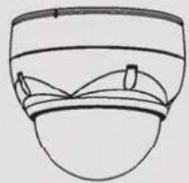
Close-up of a white security camera with black dome and lens (no visible text or symbols)
text_image
REVO ELITEHDModel No.: REHVDPTZ22-1
(DC 12V 1.0A)
REVO AMERICA
700 FREEPORT PARKWAY SUITE 100 COPPELL,
TX 75019 U.S.A TEL.: 1-866-625-REVO(7386)
Please read this manual thoroughly before use and keep it handy for future reference.
WARNING
TO REDUCE THE RISK OF FIRE OR ELECTRIC SHOCK, DO NOT EXPOSE THIS PRODUCT TO RAIN OR MOISTURE. DO NOT INSERT ANY METALLIC OBJECTS THROUGH THE VENTILATION GRILLS OR OTHER OPENINGS ON THE EQUIPMENT.
CAUTION
text_image
CAUTION RISK OF ELECTRIC SHOCK DO NOT OPEN CAUTION: TO REDUCE THE RISK OF ELECTRIC SHOCK, DO NOT REMOVE COVER(OR BACK). NO USER-SERVICEABLE PARTS INSIDE. REFER SERVICING TO QUALIFIED SERVICE PERSONNEL.EXPLANATION OF GRAPHICAL SYMBOLS
text_image
Warning symbol image showing a lightning bolt inside a triangle with a downward arrowThe lightning flash with arrowhead symbol, within an equilateral triangle, is intended to alert the user to the presence of uninsulated “dangerous voltage” within the product’s enclosure that may be of sufficient magnitude to constitute a risk of electric shock to persons.

text_image
Warning symbol image with exclamation mark inside a triangleThe exclamation point within an equilateral is intended to alert the user to the presence of important operating and maintenance (servicing) instructions in the literature accompanying the appliance.
FCC COMPLIANCE STATEMENT
FCC INFORMATION: This equipment has been tested and found to comply with the limits for a Class A digital device, pursuant to Part 15 of the FCC Rules. These limits are designed to provide reasonable protection against harmful interference when the equipment is operated in a commercial environment. This equipment generates, uses, and can radiate radio frequency energy and, if not installed and used in accordance with the instruction manual, may cause harmful interference to radio communications. Operation of this equipment in a residential area is likely to cause harmful interference in which case the user will be required to correct the interference at his own expense.
CAUTION: Changes or modifications not expressly approved by the party responsible for compliance could void the user's authority to operate the equipment.
This Class A digital apparatus complies with Canadian ICES-003.
This is a Class A product. In a domestic environment this product may cause radio interference in which case the user may be required to take adequate measures.
- Read these instructions.
- Keep these instructions.
- Heed all warnings.
- Follow all instructions.
- Do not use this apparatus near water.
-
Clean only with dry cloth.
-
Do not block any ventilation openings. Install in accordance with the manufacturer's instructions.
-
Do not install near any heat sources such as radiators, heat registers, stoves, or other apparatus (including amplifiers) that produce heat.
-
Do not defeat the safety purpose of the polarized or grounding-type plug. A polarized plug has two blades with one wider than the other. A grounding type plug has two blades and a third grounding prong. The wide blade or the third prong are provided for your safety. If the provided plug does not fit into your outlet, consult an electrician for replacement of the obsolete outlet.
-
Protect the power cord from being walked on or pinched particularly at plugs, convenience receptacles, and the point where they exit from the apparatus.
-
Only use attachments/accessories specified by the manufacturer.
-
Use only with the cart, stand, tripod, bracket, or table specified by the manufacturer, or sold with the apparatus. When a cart is used, use caution when moving the cart/apparatus combination to avoid injury from tip-over.

natural_image
Silhouette of a person climbing a ladder inside a circle with a diagonal line (no text or symbols)-
Unplug this apparatus during lightning storms or when unused for long periods of time.
-
Refer all servicing to qualified service personnel. Servicing is required when the apparatus has been damaged in any way, such as power-supply cord or plug is damaged, liquid has been moisture, does not operate normally, or has been dropped.
-
CAUTION – THESE SERVICING INSTRUCTIONS ARE FOR USE BY QUALIFIED SERVICE PERSONNEL ONLY. TO REDUCE THE RISK OF ELECTRIC SHOCK DO NOT PERFORM ANY SERVICING OTHER THAN THAT CONTAINED IN THE OPERATING INSTRUCTIONS UNLESS YOU QRE QUALIFIED TO DO SO.
-
Use satisfy clause 2.5 of IEC60950-1/UL60950-1 or Certified/Listed Class 2 power source only.
Table of Contents
Chapter 1 — Introduction ....1
1.1 Features ....1
Chapter 2 — Installation and Configuration....2
2.1 Package Contents....2
2.2 Installation....3
2.3 Basic Configuration of Dome Camera System....5
2.4 Setting Dome Camera Address (ID)....6
2.5 Connections....6
2.6 IP Assignment ....7
2.7 Getting Started ....8
Chapter 3 — Program and Operation....9
3.1 Dome Camera Selection ....9
3.2 Accessing the On-Screen Menu Utility 9
3.3 How to control the On-Screen Menu Utility....9
3.4 Auto Scan (Shortcut: SCAN)....10
3.5 Preset (Shortcut: PRST) 12
3.6 Shortcut of Preset Program....13
3.7 Tour (Shortcut: TOUR) 14
3.8 Pattern (Shortcut: PTRN)....16
3.9 Area Title....17
3.10 Privacy Zone....18
3.11 Camera Menu....19
3.12 Dome Setup ...... 22
3.13 Dome Communication ....28
3.14 Function Run....29
3.15 Factory Setup....29
Chapter 4 — Operation by Web Browser ....30
4.1 Access from a browser....30
4.2 Access from the internet 31
4.3 Setting the admin password over a secure connection....31
4.4 Live View Page 31
4.5 Network Camera Setup ....33
4.5.1 Basic Configuration....34
1) Users 34
2) Network.... 35
3) Video & Image 36
4) Audio 38
5) Date & Time 39
4.5.2 Video & Image 40
1) Basic 40
2) Webcasting – Channel1.... 40
4.5.3 Audio 41
4.5.4 Event....41
1) Event-In.... 41
2) Event-Out 45
3) Event Map 52
4.5.5 System ....53
1) Information 54
2) Security 54
3) Date & Time 57
4) Network....58
5) Language 65
6) Maintenance 65
7) Support 66
4.5.6 About 67
4.6 PTZ Control 67
4.7 Help 69
4.8 Resetting to the factory default settings....69
4.9 System Requirement for Web Browser ....70
Appendix A — Specifications....71
Appendix B — Troubleshooting ....74
Appendix C — Glossary....74
Appendix D — Short Cut Key ....77
Chapter 1 — Introduction
1.1 Features
The dome camera and the keyboard controller, PC software makes up the building blocks for any surveillance/security system. Using multiple keyboard controllers and multiple dome cameras, no place is too large for monitoring. Extensible and flexible architecture facilitates remote control functions for a variety of external switching devices such as multiplexers and DVRs.
• Built-in optical power zoom camera with True Night Shot function
- Dual video streams simultaneously at full frame rate in all resolutions up to D1 (720X480 in NTSC, 720X576 in PAL) using Motion JPEG and H.264 (or MPEG-4)
- Intelligent capabilities such as enhanced video motion detection
The encoder's external inputs and outputs can be connected to devices such as sensors and relays, enabling the system to react to alarms and activate lights or open/close doors.
• Supports two-way audio
- Logs all user access, and lists currently connected users. Also, full frame rate video can be provided over HTTPS.
- Interface Protocol: TCP/IP, UDP, IPv4/v6, HTTP, HTTPS, QoS, FTP, SNMP, uPnP, RTP, RTSP, RTCP, DHCP, ARP
- 120 Preset positions with the individual Camera AE setup
- 4 Tours consist of Presets, Patterns, Auto Scans and other Tours can be programmed with over 150 functions and Preset locations. While moving, each Preset scan can be watched in smooth Vector Scan mode.
- 4 Auto Scans with the normal, the vector, and the random mode and the Endless Auto-Pan with 13 speed steps
- 4 Patterns (up to 200 second) and 4 Privacy Zones
- 8 Area Titles
• 1 Alarm input / 1 Alarm output
- Variable speed from 0.1^ / sec to 380^ / sec Three Variable speed (SLOW, NORMAL, TURBO)
Turbo speed is 380°/sec with Ctrl key pressed.
- Pan / Tilt speed is inversely proportional to the zoom ratio with the option.
• Maximum speed is 380^/sec when Preset command.
- Auto Calibration from 0.1^ to 6^ (Tilt range is 0^ to 180^ )
- Programmable user preferences (alarm, preset, title, etc.)
- 180° Digital Flip
- Up to 255 selectable camera addresses
- Multi-language Menu Display, Password Confirmation
- Function Run menu using DVR without function key (Pattern, Scan, ...)
• Built-in RS-485 receiver driver
• 12VDC for Dome
- Use satisfy clause 2.5 of IEC60950-1/UL60950-1 or Certified/Listed Class 2 power source only.
Chapter 2 — Installation and Configuration
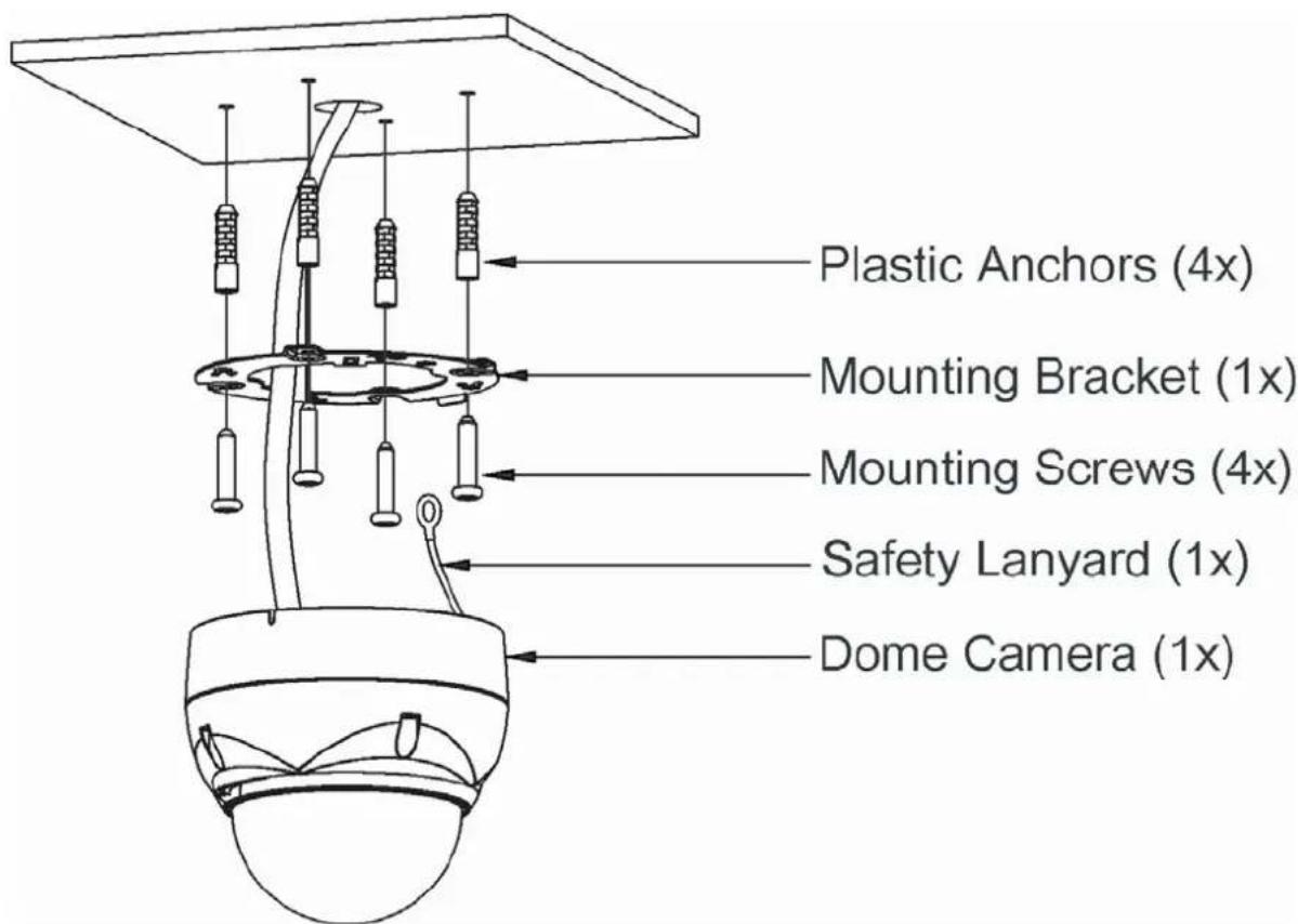
2.1 Package Contents
The dome camera is design to a compact, small size, hard dome camera housing.
The housing is constructed of aluminum, steel and plastic. The housing is designed to be mounted both wall and ceiling type.
The housing meets the Protection Classification IP66 standards for dust and moisture resistance.
* Dome Camera 1
* Installation Guide/CD 1
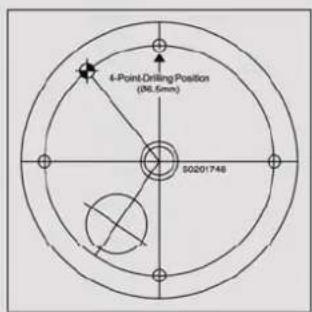
* Template Sheet 1
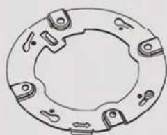
* Mounting ....Bracket....1
* Safety Lanyard 1
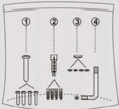
* Accessory Kit 1
1) Mounting screws (PH6 x 35.0) ____ (4)
2) Plastic anchors (4)
3) O-Rings (4)
4) Torx wrench (1)
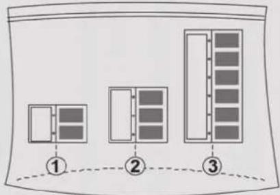
* Accessory Connector 1
1) 2Pin Terminal Block ____ (1)
2) 3Pin Terminal Block ____ (1)
3) 6Pin Terminal Block ..... (1)
natural_image
Simple line drawing of a bowl with a lid and cup (no text or symbols)Dome Camera

text_image
GuideInstallation Guide/CD
text_image
Diagram showing three labeled panels (①, ②, ③) with different panel sizes and shading patterns, likely illustrating a layout or design concept.Accessory connector
natural_image
Circular mechanical component diagram with six evenly spaced notches and a central hole (no text or symbols)Mounting Bracket

Safety Lanyard
text_image
4-Point-Drilling Position (96.5mm) 50201748Template sheet
text_image
Diagram showing four labeled parts of a medical or laboratory procedure with pipettes and tubing, likely for surgical or laboratory procedures.Accessory kit
2.2 Installation
The dome camera is for use in surface or pendent mounting applications and the mounting member must be capable of supporting loads of up to 3.5lb (1.6kg). (Pendent mounting must use pendent mount accessory.)
The dome camera's mounting bracket should be attached to a structural object, such as hard wood, wall stud or ceiling rafter that supports the weight of the dome camera.
text_image
Plastic Anchors (4x) Mounting Bracket (1x) Mounting Screws (4x) Safety Lanyard (1x) Dome Camera (1x)CAUTION: A silicone rubber sealant must be applied to seal the housing to secure waterproofing.
2.2.1 Locking Dome Camera
A. Make screw holes on the ceiling using the supplied mounting Template Sheet (Figure A).
B. Fix the Mounting Bracket using Anchors(4x) and Mounting Screws(4x) to the ceiling (Figure B).
C. Hook up the Safety Lanyard to the Safety Lanyard Hook of the Mounting Bracket (Figure C).
D. Align the locking tap on the bracket and the locking slot on the base of the dome (Figure D).
E. Turn the dome to the counterclockwise about 10 degree to the locked position (Figure E).
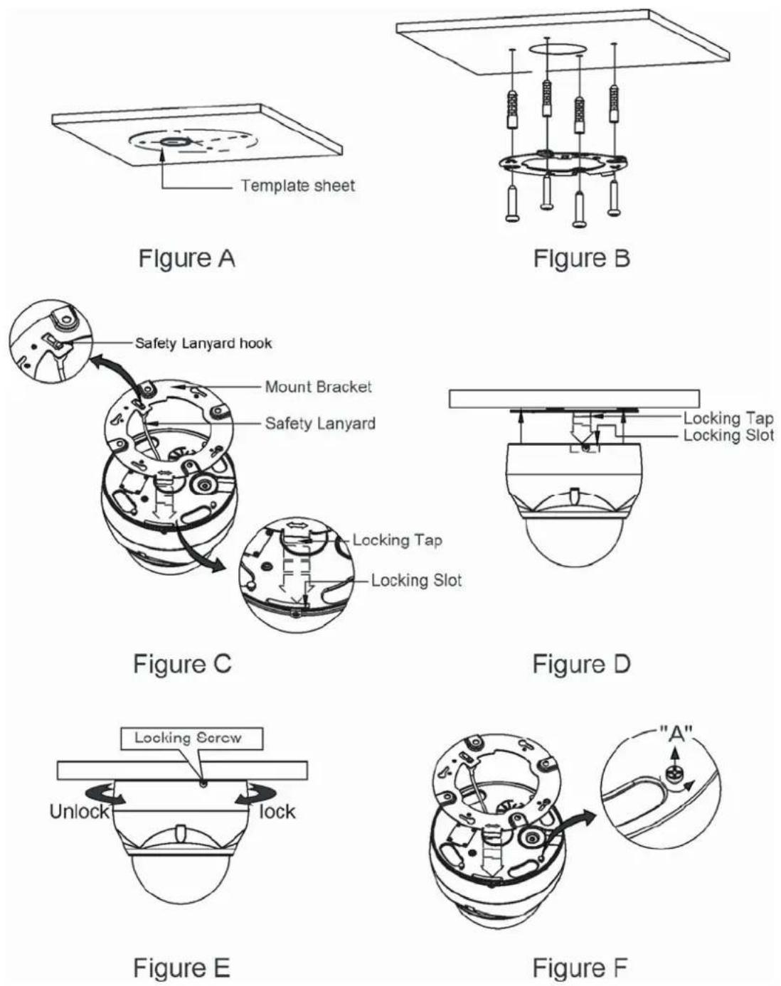
CAUTION: Before installing mounting bracket to surface pre-adjust the four mounting screws "A" on the base of the dome camera to best match the mounting bracket locked position. Unscrew the locking screw on the side of the dome's base and fit the tab of the mounting bracket into the locking slot. Screws "A" should not be too tight or too loose when the dome is in the locked position. After setting the proper positions of screws "A" remove the mounting bracket and install it to the proper surface. If it is too difficult to lock the dome in position after the mounting bracket has been installed readjust the screws "A" by unscrewing them a small amount and try to install dome camera again.
2.3 Basic Configuration of Dome Camera System
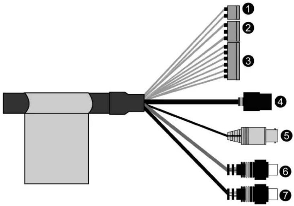
text_image
Diagram showing connector wiring with numbered pins from pin 1 to pin 7, illustrating cable connection and connector layout.| No. | Wire Color Description | |
| 1 | Red: 12VDC+White: 12VDC- | Main Power: 2pin terminal |
| 2 | Pink, Brown Heater Power(Option): 3pin terminal | |
| 3 | Black: GNDGray: Alarm InputYellow: GNDBlack&White: Alarm OutputGreen: RS485+Blue: RS485- | Alarm Input/Output, RS485: 6pin terminal |
| 4 | Black Ethernet: RJ45 Modular Jack | |
| 5 | Yellow Video Composite Output: BNC Jack | |
| 6 | Red Audio line output: RCA Jack | |
| 7 | White Audio line input: RCA Jack | |
The dome camera must be installed by qualified service personnel in accordance with all local and federal electrical and building codes.
2.4 Setting Dome Camera Address (ID)
To prevent damage, each dome camera must have a unique address (ID).
When installing multiple dome cameras using a multiplexer, it is suggested that the dome camera address match the multiplexer port number.
The factory default setting is 1.
Refer to '3.13 Dome Communication' section for detailed information.
2.5 Connections
- Connecting to the RJ-45
Connect a standard RJ-45 cable to the network port of the dome camera. Generally a cross-over cable is used for directly connection to PC, while a direct cable is used for connection to a hub.
- Connecting Alarms
AI (Alarm Input)
You can use external devices to signal the dome camera to react on events. Mechanical or electrical switches can be wired to the AI (Alarm Input) and G (Ground) connectors.
Please see "4.5.4 Event > 1) Event-In > ② Alarm In" for configuring alarm input.
G (Ground)
NOTE: All the connectors marked G or GND are common.
Connect the ground side of the alarm input and/or alarm output to the G (Ground) connector.
AO (Alarm Output)
The dome camera can activate external devices such as buzzers or lights. Connect the device to the AO (Alarm Output) and G (Ground) connectors.
Please see "4.5.4 Event > 2) Event-Out > ④ Alarm Out" for configuring alarm output.
- Connecting to the RS485
The dome camera can be controlled remotely by an external device or control system, such as a control keyboard, using RS485 half-duplex serial communications signals.
- Connecting Video out connector
Connect the video out (BNC) connector to the monitor or video input.
- Connecting the Power
Connect the power of 12VDC 1.0A for the dome camera.
When using a 12VDC adapter, connector the positive(+) pole to the '+' position and the negative(-) pole to the '-' position.
Use satisfy clause 2.5 of IEC60950-1/UL60950-1 or Certified/Listed Class 2 power source only.
2.6 IP Assignment
When the dome camera, encoder or decoder is first connected to the network it has no IP address. So, it is necessary to allocate an IP address to the device with the "SmartManager" utility on the CD.
-
Connect the dome camera / device to the network and power up.
-
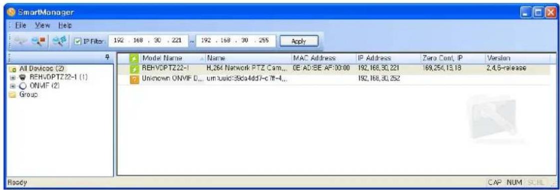
Start SmartManager utility (Start>All programs>SmartManager>SmartManager), the main window will be displayed, after a short while any network devices connected to the network will be displayed in the list.
text_image
SmartManager File View Help IP Filter 192 . 168 . 30 . 221 192 . 158 . 30 . 255 Apply All Devices (2) REHVDPTZ22-1 (1) ONVIF (2) Group Model Name Name MAC Address IP Address Zero Cont, IP Version REHVDPTZ22-1 H,264 Network PTZ Cam... GE:AD:BE:AF:00:00 192,168,30,221 169,256,13,18 2,4,5-release Unknown ONVIF D... um build:39da4dd7-c If-4... 192,168,30,252 Ready CAP NUM SCHL- Select the dome camera on the list and click right button of the mouse.
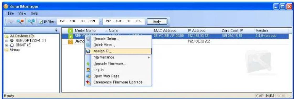
You can see the pop-up menu as below.
text_image
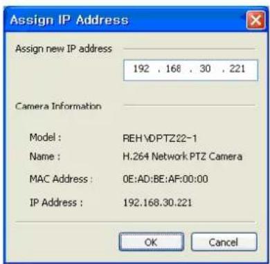
SmartManager File View Help IP Filter: 192 . 168 . 30 . 221 .. 192 . 168 . 30 . 255 Apply All Devices (2) REHVDPTZ22-1 (1) ONVF (2) Group Model Name Name MAC Address IP Address Zero Cont, IP Version REHVDPTZ22-1 (1) Unlnd Remote Setup... CE AD/EE AF:00:00 192,168,30,221 169,254,13,18 2,4,5-release Quick View... 192,168,30,252 Assign IP... Maintenance Upgrade Firmware... Log In Open Web Page Emergency Firmware Upgrade Ready CAP NUM SCHL- Select Assign IP Address. You can see Assign IP window. Enter the required IP address.
text_image
Assign IP Address Assign new IP address 192 , 168 , 30 , 221 Camera Information Model : REH\DPZ22-1 Name : H.264 Network PTZ Camera MAC Address : 0E:AD:BE:AF:00:00 IP Address : 192.168.30.221 OK CancelNote: For more information, refer to the SmartManager User's Manual.
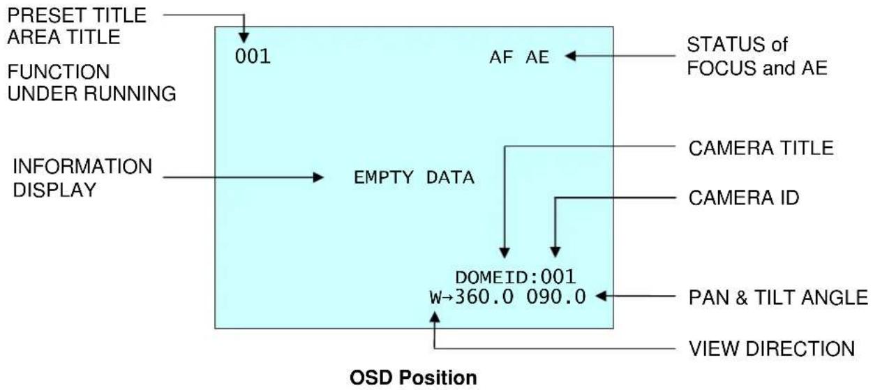
2.7 Getting Started
Once installed apply power to the dome camera. The dome camera will start a configuration sequence.
flowchart
graph TD
    A["001"] --> B["PRESENT TITLE AREA TITLE FUNCTION UNDER RUNNING"]
    B --> C["INFORMATION DISPLAY"]
    C --> D["EMPTY DATA"]
    D --> E["AF AE"]
    E --> F["STATUS of FOCUS and AE"]
    D --> G["CAMERA ID"]
    D --> H["CAMERA TITLE"]
    D --> I["DOMEID:001 w→360.0 090.0"]
    I --> J["PAN & TILT ANGLE"]
    I --> K["VIEW DIRECTION"]
    style A fill:#cce5ff,stroke:#333
    style B fill:#cce5ff,stroke:#333
    style C fill:#cce5ff,stroke:#333
    style D fill:#cce5ff,stroke:#333
    style E fill:#cce5ff,stroke:#333
    style F fill:#cce5ff,stroke:#333
    style G fill:#cce5ff,stroke:#333
    style H fill:#cce5ff,stroke:#333
    style I fill:#cce5ff,stroke:#333
    style J fill:#cce5ff,stroke:#333
    style K fill:#cce5ff,stroke:#333
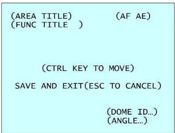
The dome can move the OSD position in the OSD position setup.
text_image
(AREA TITLE) (AF AE) (FUNC TITLE ) (CTRL KEY TO MOVE) SAVE AND EXIT(ESC TO CANCEL) (DOME ID...) (ANGLE...)OSD Position Setup
Chapter 3 — Program and Operation
3.1 Dome Camera Selection
Before you program or operate a dome camera, you must select the dome camera by pressing No. + CAM keys.
Example: Pressing 1, 0 + CAM keys sequentially will select dome camera 10. The selected dome camera ID will be displayed on the LCD monitor of the keyboard controller.
3.2 Accessing the On-Screen Menu Utility
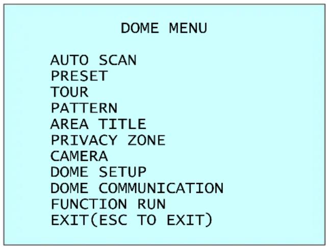
You can call up the On-screen menu utility on your monitor by pressing the MENU key on the keyboard controller, the following On-screen menu utility will appear:
text_image
DOME MENU AUTO SCAN PRESET TOUR PATTERN AREA TITLE PRIVACY ZONE CAMERA DOME SETUP DOME COMMUNICATION FUNCTION RUN EXIT(ESC TO EXIT)3.3 How to control the On-Screen Menu Utility
| Function Button | |
| Call the On-screen menu utility. | MENU |
| Navigate through the menu items. | Joystick up or down |
| Go into the sub-menu items. | Joystick left or right or IRIS Open |
| Change value.Enter the editing title mode. | Joystick left or right or Zoom handle twist or Tele, Wide |
| Change value of angle. | CTRL + Joystick |
| Enter the changing angle mode. | IRIS Open |
| Exit the changing angle mode. | IRIS Close |
| Escape (EXIT) | ESC |
3.4 Auto Scan (Shortcut: SCAN)
The Auto Scan supports up to 5 programmed angles at user-programmable speeds. Follow these steps to program Auto Scan:

text_image
AUTO SCAN SETUP NUMBER : 01 TITLE : A01 MODE : NORMAL SPEED : 5 STEP START ANGLE : ---- -- END ANGLE : ---- -- SCAN DIR : CCW SWAP : OFF DWELL : 03 SEC SAVE AND EXIT(ESC TO CANCEL)NUMBER : 01 \~ 04, 09:AUTO PAN mode.
TITLE : up to 12 characters.
MODE : NORMAL, VECTOR, RANDOM (AUTO PAN mode: NORMAL, RANDOM only).
NORMAL : Move from start point to end point in panning only.
VECTOR : Move from start point to end point including tilt and zoom simultaneously and linearly.
RANDOM : Move randomly between the start point and the end point.
SPEED : 01 \~ 13 step, the lower number means the slower speed.
SCAN DIR : Set the Scan direction, CCW(Counter Clock Wise), CW(Clock Wise).
SWAP : Swap the start point for the end point.
DWELL : Set the dwell time at the both end, 01 \~ 99 seconds.
-
Press the SCAN key to enter the Auto Scan menu directly. Or press the MENU key to display the main menu on the monitor. Scroll to Auto Scan and push the Joystick to the right.
-
Select "NUMBER" and set the desired number by pushing the Joystick to the left or right.
-
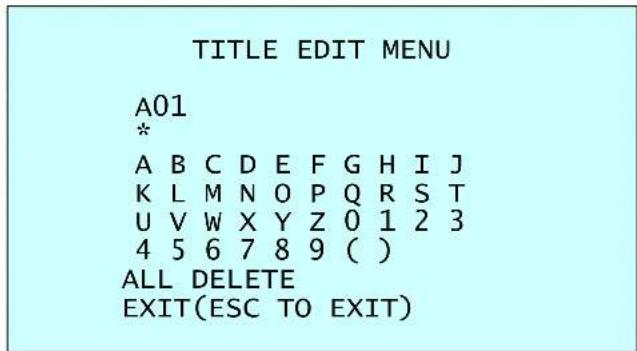
Select "TITLE" and twist the Joystick to enter the title edit mode.
-
Twist the Joystick by changing the alphanumeric characters and move the next position. Or move down to the character table and press the CTRL or IRIS Open key at the desired character then the cursor position moves to the next position automatically. Push the Joystick to the left or right at the "ALL DELETE" field to delete all characters. Push the Joystick to the left or right at the "EXIT" field to finish title edit menu.
text_image
TITLE EDIT MENU A01 * A B C D E F G H I J K L M N O P Q R S T U V W X Y Z 0 1 2 3 4 5 6 7 8 9 ( ) ALL DELETE EXIT(ESC TO EXIT)-
Select "MODE" and "SPEED".
-
Select "START ANGLE". Hold down the CTRL key while selecting the start position using the Joystick. Current panning position will be displayed. Release the CTRL key to complete the selection of the start position. Or press the IRIS Open key then the "CTRL" displays. Move the desired position and the zoom position. Press the IRIS Close key then the "CTRL" disappears. To adjust at the 0.1 degree interval, twist the Joystick at the pan field and the tilt field. To adjust at the one zoom interval, twist the Joystick at the zoom field.
-
Select "END ANGLE". Hold down the CTRL key while moving the Joystick to select the end position. The end position angle should be larger than start position. Release the CTRL key to complete the selection of the end position. Or press the IRIS Open key then the "CTRL" displays. Move the desired position and the zoom position. Press the IRIS Close key then the "CTRL" disappears. To adjust at the 0.1 degree interval, twist the Joystick at the pan field and the tilt field. To adjust at the one zoom interval, twist the Joystick at the zoom field.
-
Set "SCAN DIR" to CCW or CW.
-
Select "SWAP", Set to ON, to exchange the start angle and the end angle.
-
Set "DWELL TIME".
-
Select "SAVE AND EXIT" and push the Joystick to the right or press the IRIS Open key. Press the ESC or IRIS Close key to exit the program without saving.
NOTE: Pressing the HOME key delete stored data at the angle field.
To set the position using the Preset position:
a. Before entering the Auto Scan menu, select a Preset position as a starting point for Auto Scan.
Example: 2 + PRST keys and do step 1 to 5. In step 6, just press the Ctrl key at the start angle position, the current position will be displayed as a start position.
b. Save and exit from the menu.
c. In normal mode, call a Preset to be the end point of Scan. Press 3 + PRST keys then press the SCAN key to enter the Auto Scan menu. Move the cursor position to END ANGLE. Just press the CTRL key at the end angle position. Save and exit from the menu.
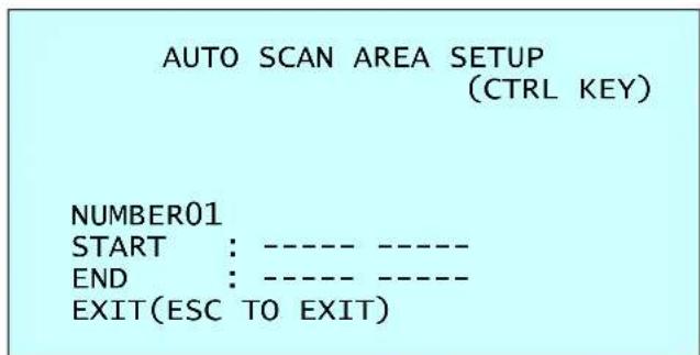
Press the SCAN key on the angle field to display with the small OSD. Then the screen will show as below.
text_image
AUTO SCAN AREA SETUP (CTRL KEY) NUMBER01 START : ---- ---- END : ---- ---- EXIT(ESC TO EXIT)The setting procedure is the same as above.
NOTE: 09: AUTO-PAN mode (Endless panning)
3.5 Preset (Shortcut: PRST)
If you need to view specific places routinely, you should program Presets. A Preset is a programmed video scene with automatic pan, tilt, zoom, focus and AE settings. Once programmed, placing the number position and pressing the PRST key on your controller calls up that Preset automatically. In addition, Presets may be assigned to alarm action or as the "home" position for the dome camera. As many as 120 Presets, whose positions are saved in the dome's firmware, may be programmed.
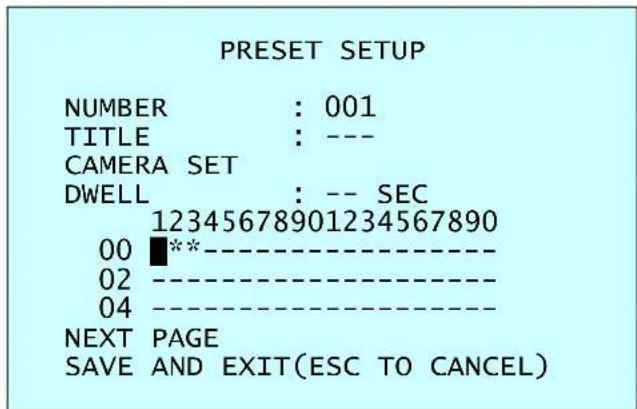
There are two pages of Preset menu. Each page has 60 Presets. Pages can be scrolled by pushing the Joystick to the left or right on the first or last No. of Preset.
text_image
PRESET SETUP NUMBER : 001 TITLE : --- CAMERA SET DWELL : -- SEC 12345678901234567890 00 ****** 02 ----** 04 ----** NEXT PAGE SAVE AND EXIT(ESC TO CANCEL)- : blank Preset position
* : position has the Preset
■ : current cursor position
Follow steps below to store the Preset positions:
- Press the PRST key to enter the Preset menu directly. Or press the MENU key to display the main menu on the monitor. Scroll to Preset and push the Joystick to the right.
- Select the blank Preset position to be stored by pushing the Joystick up, down, right, or left.
- After selecting a blank position, press and hold the CTRL key. Use the Joystick to control the direction of the camera and lens.
- After aiming the camera (view direction and lens control), release the CTRL key. The cursor will be on the "TITLE" after saving data then twist the Joystick or press the Tele or Wide key to edit the Preset title. Follow the procedure of the Auto Scan above to edit titles.
- Select "CAMERA SET" and pushing the Joystick to the left or right. Then the Preset camera setup displays.
PRESET CAMERA SETUP
FOCUS : AUTO AE SETUP SAVE AND EXIT(ESC TO CANCEL)
Set FOCUS : AUTO, MANUAL, ONE PUSH
Select "AE SETUP" and pushing the Joystick to the left or right. Then the AE setup displays. Refer to the AE SETUP in the camera setup.
- Set "DWELL TIME". (03 \~ 99 seconds)
- To select the next page of Presets, scroll the page by pushing the Joystick to the left on the first and last columns of the menu.
- Repeat step 2 through 7 for each additional Preset position.
- Select "SAVE AND EXIT" and push the Joystick to the right or press the IRIS Open key. Press the ESC or IRIS Close key to exit the program without saving.
NOTE: Press the HOME key at programmed Preset position(*) to delete a programmed Preset view.
The position, which is marked with the *, already has the Preset view assigned. To review the stored Preset, press the PRST key on the *. The camera will show the stored Preset scene.
PRESET AREA SETUP
(CTRL KEY)
NUMBER 001
PAN TILT
000.0 000.0
EXIT(ESC TO EXIT)
Hold down the CTRL key while selecting the desired scene using the Joystick. Current position will be displayed. Release the CTRL key to complete. Or Press the IRIS Open key then the "CTRL" displays. Move the desired position and the zoom position. Press the IRIS Close key then the "CTRL" disappears. Select "EXIT" and push the Joystick to the right.
3.6 Shortcut of Preset Program
After selecting the desired scene, press No. (1 to 120), and press the CTRL and PRST keys subsequently. The current view will be stored to the selected Preset number if the Preset number is empty. If selected Preset number is not empty, "OVER WRITE" message will be displayed on the monitor and select the "OK" and push the Joystick to the right to overwrite.
Example: 1, 0, 1 + CTRL + PRST keys will store current view as Preset no. 101. In this case, focus will be programmed as Auto, dwell time will be set to 3 second, and the current AE mode will be programmed.
3.7 Tour (Shortcut: TOUR)
There are 4 programmable Tours. Each Tour consists of up to 42 Preset positions, Patterns, Scans or other Tours (second-level). Using second-level Tours, it can be expanded to over 150 functions in a single Tour.
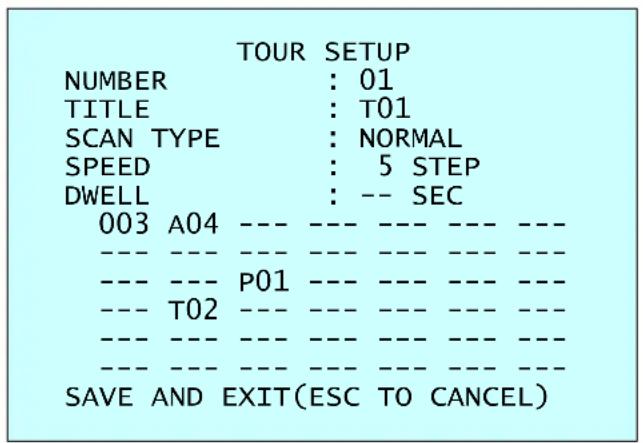
text_image
TOUR SETUP NUMBER : 01 TITLE : T01 SCAN TYPE : NORMAL SPEED : 5 STEP DWELL : -- SEC 003 A04 --- --- --- --- --- --- --- --- --- --- --- --- --- --- P01 --- --- --- --- --- --- T02 --- --- --- --- --- --- --- --- --- --- --- --- --- --- --- --- --- --- --- SAVE AND EXIT(ESC TO CANCEL)--- : blank position
SCAN TYPE : NORMAL, VECTOR
DWELL : 03 \~ 99 SEC
003 : Preset (1 \~ 120)
A04 : Auto Scan (1 \~ 4)
P01 : Pattern (1 \~ 4)
T02 : Tour (1 \~ 4)
Follow the steps below to program the Tours:
- Press the MENU key to display the main menu on the monitor. Scroll to Tour and push the Joystick to the right to enter the Tour menu. Or just press the TOUR key on the keyboard.
- Select "NUMBER" and set the desired number by pushing the Joystick to the left or right.
- Choose a blank position to be programmed by pushing the Joystick up, down, right, or left.
- To add a stored Preset, twist the Joystick then the stored Preset number displays.
- To place functions other than Preset, press the TOUR, PTRN, or SCAN keys for Tour, Pattern or Auto Scan respectively.
- You can also overwrite the programmed number and to remove a stored number from the Tour, press the HOME key on the stored number, a blank position mark (---) will be displayed.
- Repeat step 2 through 6 for each desired position. Each title will be displayed on top of the line.
- To edit the "TITLE", follow the procedure of the Auto Scan above to edit titles.
- Select "SAVE AND EXIT" and push the Joystick to the right or press the IRIS Open key. Press the ESC or IRIS Close key to exit the program without saving.
You can expand the Tour sequence by calling other programmed Tours.
NOTE: The speed applies in the vector mode only.
NOTE: In the Tour mode, in conjunction with Preset and Auto Scan, you can make the camera travel from a Preset position to another Preset position at a specific speed.
Example: Preset 001>002>003>004>005>006, Auto Scan 01 starts at Preset 002, ends at Preset 003, Auto Scan 02 starts at Preset 005, ends at Preset 006; Tour 001, 002, A01, 004, A02.
1 → 2 2\~3 → 4 → 5\~6, repeat
where → : Quick move, \~ : Programmed speed
To change the dwell time of the Preset in the Tour:
Use the Joystick to move the cursor to a stored Preset position.
By pressing the PRST key, the camera will move to the stored Preset view and the cursor moves to the dwell time field.
After changing the dwell time, press the PRST key and the cursor moves to the Preset number.
To assign the functions other than Preset in the Tour when the function key is not existed:
Use the Joystick to move the cursor to a stored Preset position.
Pressing the CTRL or IRIS Open key will change the Preset number to other function (Auto Scan, Pattern, Tour, Preset) with the first programmed number.
To change the number, twist the Joystick or press the Tele or Wide key.
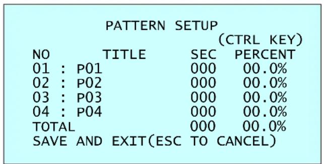
3.8 Pattern (Shortcut: PTRN)
The Pattern feature records user control of the selected dome camera. Up to 4 Patterns can be stored and played back by pressing No. + PTRN keys subsequently.
text_image
PATTERN SETUP (CTRL KEY) NO TITLE SEC PERCENT 01 : P01 000 00.0% 02 : P02 000 00.0% 03 : P03 000 00.0% 04 : P04 000 00.0% TOTAL 000 00.0% SAVE AND EXIT(ESC TO CANCEL)Follow steps below to program the Pattern:
- Press the MENU key to display the main menu on the monitor. Scroll to Pattern and push the Joystick to the right to enter the Pattern menu. Or just press the PTRN key on the keyboard.
- Select the desired Pattern to be programmed by pushing the Joystick up or down. If the Pattern is not 000, a Pattern has already been recorded. Patterns can be overwritten.
- Press and hold down the CTRL key while controlling the camera direction and zoom with the Joystick. The dome will be automatically recorded until you release the CTRL key. Or press the IRIS Open key then the "CTRL" displays. Move the position and the zoom position. Press the IRIS Close key then the "CTRL" disappears.
- To edit the "TITLE", follow the procedure of the Auto Scan above to edit titles.
- Select "SAVE AND EXIT" and push the Joystick to the right or press the IRIS Open key. Press the ESC or IRIS Close key to exit the program without saving.
NOTE: Press the HOME key at any programmed position to delete the Pattern.
NOTE: If Pattern recording time reaches 200 seconds, it will automatically stop for a moment.
Press the PTRN key on the title field to display with the small OSD. Then the screen will show as below.
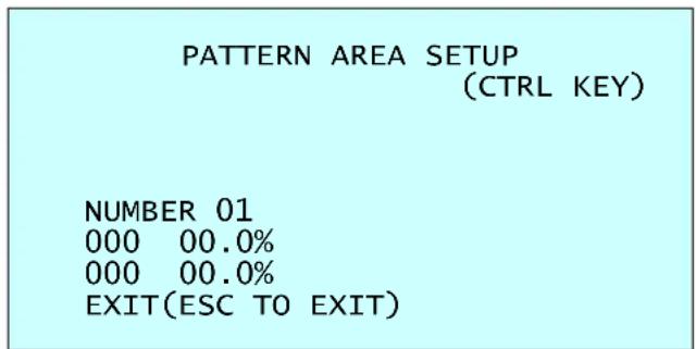
text_image
PATTERN AREA SETUP (CTRL KEY) NUMBER 01 000 00.0% 000 00.0% EXIT(ESC TO EXIT)The setting procedure is the same as above.
3.9 Area Title
Enter a specific name on programmed angle between START and END. For the screen below, when the camera points at an angle between 124.3° (PAN), 30.7° (TILT) to 359.5° (PAN), 45.4° (TILT), ABC will be displayed on the screen.
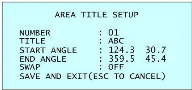
text_image
AREA TITLE SETUP NUMBER : 01 TITLE : ABC START ANGLE : 124.3 30.7 END ANGLE : 359.5 45.4 SWAP : OFF SAVE AND EXIT(ESC TO CANCEL)NUMBER : 01 \~ 08
TITLE : up to 12 characters.
SWAP : Swap the start point for the end point.
- Select "NUMBER" and set the desired number by pushing the Joystick to the left or right.
- To edit the "TITLE", follow the procedure of the Auto Scan above to edit titles.
- Select "START ANGLE". Hold down the CTRL key while selecting the start position using the Joystick. Current panning position will be displayed. Release the CTRL key to complete the selection of the start position. Or press the IRIS Open key then the "CTRL" displays. Move the desired position. Press the IRIS Close key then the "CTRL" disappears. To adjust at the 0.1 degree interval, twist the Joystick at the pan field and the tilt field.
- Select "END ANGLE". Hold down the CTRL key while moving the Joystick to select the end position. Release the CTRL key to complete the selection of the end position. Or press the IRIS Open key then the "CTRL" displays. Move the desired position. Press the IRIS Close key then the "CTRL" disappears. To adjust at the 0.1 degree interval, twist the Joystick at the pan field and the tilt field.
- Select "SWAP". Set to ON, to exchange the start angle and the end angle.
- Select "SAVE AND EXIT" and push the Joystick to the right or press the IRIS Open key. Press the ESC or IRIS Close key to exit the program without saving.
3.10 Privacy Zone
Hide up to 4 unwanted scenes in a camera.
| PRIVACY ZONE SETUP | ||
| (CTRL KEY) | ||
| NO | TITLE | METHOD |
| 01 | ABC | ON BLOCK |
| 02 | DEF | ON V.OFF |
| 03 | OFF ---- | |
| 04 | OFF ---- | |
| SAVE AND EXIT(ESC TO CANCEL) | ||
-
Place the cursor at the title field.
-
Hold down the CTRL key displays the privacy area menu while selecting the position using the Joystick. Current position will be displayed. Release the CTRL key to complete the selection of the position.
Or press the IRIS Open key then the privacy area menu displays. Move the desired position. Press the IRIS Close key then the "CTRL" disappears and returns to the previous menu.
PRIVACY AREA MENU
(CTRL KEY)
CONTROL
NUMBER 001
354.8 344.8
-
Place the cursor at the "TITLE" field. Twist the Joystick to enter the title edit mode. Follow the procedure of the Auto Scan above to edit titles.
-
To turn the stored zone On or Off, twist the Joystick or press the Tele or Wide key.
-
Set the "METHOD", "BLOCK" or "V.OFF(video off)".
-
Select "SAVE AND EXIT" and push the Joystick to the right or press the IRIS Open key. Press the ESC or IRIS Close key to exit the program without saving.
NOTE: Press the HOME key to delete programmed Privacy Zone at the title field.
3.11 Camera Menu
CAMERA SETUP
FOCUS CONTROL
WB CONTROL
AE CONTROL
DNR CONTROL
SHARPNESS : 07
RESOLUTION : MID
DIGITAL ZOOM : OFF
IMAGE FLIP : OFF
PRESET FREEZE : OFF
SAVE AND EXIT(ESC TO CANCEL)
SHARPNESS The higher the value, the more edges in the picture will be enhanced. (0 \~ 15)
RESOLUTION Select high resolution mode. (LOW / MID / HIGH)
DIGITAL ZOOM OFF: Zoom range is limited to the optical.
2X: Zoom is extendable up to 2X of digital range.
4X: Zoom is extendable up to 4X of digital range.
8X: Zoom is extendable up to 8X of digital range.
MAX: Zoom is extendable Max digital zoom range.
IMAGE FLIP This function turns the video output from the camera upside down and reverses it horizontally.
This option is helpful to install in the opposite side.
PRESET FREEZE ON: the image is frozen during calling Preset.
- FOCUS CONTROL
FOCUS SETUP
MODE : AUTO
FOCUS LIMIT : 1.0M
SAVE AND EXIT(ESC TO CANCEL)
MODE AUTO / MANUAL / ONE PUSH / CONSTANT MANUAL
Use manual mode in normal use.
FOCUS LIMIT This distance is approximate value and the focus operate from the setting value.
CAUTION: Avoid continuous, 24-hour use of the auto focus. This will shorten the lifespan of the lens.
• WB (White Balance) CONTROL
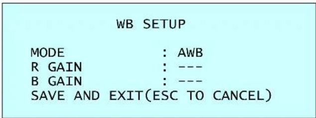
text_image
WB SETUP MODE : AWB R GAIN : --- B GAIN : --- SAVE AND EXIT(ESC TO CANCEL)MODE AWB / WAWB / INDOOR / OUTDOOR / MANUAL
AWB Computes the white balance value output using color information from the entire screen automatically. (2500 to 9500 °K)
WAWB Wide range auto white balance mode (1800 to 10500 °K)
INDOOR Indoor white balance mode
OUTDOOR Outdoor white balance mode
MANUAL Manual mode, you can change R and B Gain manually.
RGAIN 0 \~ 255
BGAIN 0 \~ 255
RGAIN / BGAIN modes are controllable only in MANUAL Mode.
- AE CONTROL
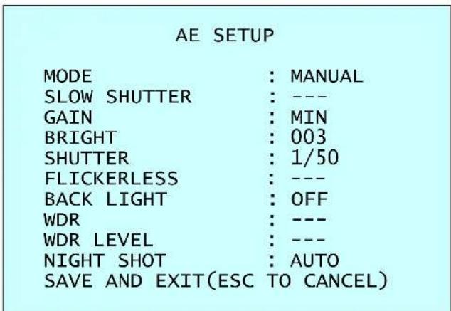
text_image
AE SETUP MODE : MANUAL SLOW SHUTTER : --- GAIN : MIN BRIGHT : 003 SHUTTER : 1/50 FLICKERLESS : --- BACK LIGHT : OFF WDR : --- WDR LEVEL : --- NIGHT SHOT : AUTO SAVE AND EXIT(ESC TO CANCEL)MODE AE1 / AE2 / SHUTTER PRIO / MANUAL
AE1 Auto exposure mode1 (Use to normal surroundings: indoor)
AE2 Auto exposure mode2 (Use to high brightness surroundings: outdoor)
SHUTTER PRIO Variable Shutter speed, Auto Gain
MANUAL Variable Shutter speed, Gain
SLOW SHUTTER ON / OFF
GAIN MIN / LOW / MID / HIGH
BRIGHT 1 \~ 15
SHUTTER 1/50(60), 1/120(100), ..., 1/2000, 1/10000, 1/100000
FLICKERLESS ON / OFF
BACK LIGHT ON / OFF (NOTE: When ON, WDR will be disabled.)
WDR ON / OFF (NOTE: When ON, BACKLIGHT will be disabled.)
WDR LEVEL 10 \~ 50
NOTE: Values in ( ) are for NTSC Camera. The WDR operates in AE1 mode only.
NOTE: When BACKLIGHT set ON, focus issues may occur in certain lighting conditions.
The NIGHT SHOT option removes the IR cutoff filter of the camera and makes the camera sensitive to near infrared.
AUTO Camera goes in to B&W mode at low light.
GLOBAL Controlled by the keyboard
(NOTE: GLOBAL function operates F2E protocol only)
The operator can enable NIGHT SHOT for all dome cameras at the same time.
If the NIGHT SHOT mode is set to GLOBAL, "999" + ENTER will turn Off the NIGHT
SHOT mode and "888" + ENTER will turn On the NIGHT SHOT mode.
ON B/W mode
OFF Color mode
NOTE: AUTO in NIGHT SHOT function is not applied in "MANUAL" mode of AE Control.
• DNR CONTROL
DNR SETUP
2DNR(1), 2DNR(2) Select 2D noise reduction level (OFF / 1 \~ 7)
3DNR(1), 3DNR(2) Select 3D noise reduction level (OFF / 1 \~ 31)
NOTE: DNR(1) applied when motor stopped. DNR(2) applied when motor moving.
3.12 Dome Setup
CONFIGURATION MENU
LANGUAGE : ENGLISH
HOME FUNCTION SETUP
OSD DISPLAY
VIEW ANGLE SETUP
INITIALIZE DATA
ORIGIN OFFSET
DOME RESET
SYSTEM MENU
SYSTEM INFORMATION
SAVE AND EXIT(ESC TO CANCEL)
- LANGUAGE SETUP
LANGUAGE : Select the language you want.
• HOME FUNCTION SETUP
HOME FUNCTION SETUP
HOME FUNCTION : NONE
FUNCTION NUMBER : ---
WAITING TIME : 120 SEC
FUNCTION ENABLE : OFF
SAVE AND EXIT(ESC TO CANCEL)
HOME FUNCTION : None / Tour / Pattern / Auto Scan / Preset
FUNCTION NUMBER : ---
WAITING TIME : 10 \~ 240 seconds
FUNCTION ENABLE : ON / OFF
The Home function can be set so that the camera automatically goes to Tour, Pattern, Auto Scan or Preset after the keyboard controller has been idle for a amount of time. For example, if the controller is idle for 120 seconds, the camera goes to Preset 1.
Follow these steps to program the Home position:
- Select "HOME FUNCTION" by pushing the Joystick to the left or right to scroll through the None, Tour, Pattern, Auto Scan or Preset functions.
- Select "FUNCTION NUMBER" and push the Joystick to the left or right. The recorded function number will scroll.
- Select "WAITING TIME" and push the Joystick to the left or right to select from 10 to 240 seconds.
- Select "FUNCTION ENABLE" and turn to ON or OFF by pushing the Joystick to the left or right.
- OSD DISPLAY
OSD DISPLAY SETUP
| CAMERA TITLE | : DOMEID |
| VIEW DIRECTION | : OFF |
| DOME OSD | : ON |
| AREA TITLE | : OFF |
| PRESET TITLE | : CONSTANT |
| FOCUS EXPOSURE | : ON |
| OSD POSITION SETUP |
SAVE AND EXIT(ESC TO CANCEL)
CAMERA TITLE : up to 6 characters.
VIEW DIRECTION : ON / OFF
"ON" sets current direction as N(North) and the coordinate angle to 000. "OFF" hides the directional title. Every 90 degrees of clockwise rotation will change the title to E(East), S(South), W(West). If using the ON/OFF option frequently, it is recommended that you set "North" as a Preset. Recall the "North" Preset before enabling the directional title.
DOME OSD : ON / OFF
All display or title will disappear when DOME OSD DISPLAY sets OFF.
AREA TITLE : ON / OFF
If this option is enabled, the area title displays when the camera moves.
NOTE: The DOME OSD DISPLAY must be enabled.
PRESET TITLE : CONSTANT / OFF / 3, 30, 60, 120, 180 seconds Set the Preset title display time.
FOCUS EXPOSURE : ON / OFF
ON: FOCUS and EXPOSURE displays. (AF AE)
OSD POSITION SETUP
Select the OSD option with the Joystick up and down, press the CTRL key and adjust the position by the Joystick.
(AREA TITLE) (AF AE) (FUNC TITLE )
(CTRL KEY TO MOVE)
SAVE AND EXIT(ESC TO CANCEL)
DOMEID:XXX XXX.X XXX.X
• VIEW ANGLE SETUP
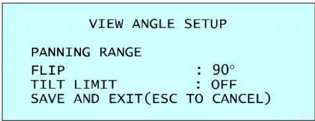
text_image
VIEW ANGLE SETUP PANNING RANGE FLIP : 90° TILT LIMIT : OFF SAVE AND EXIT(ESC TO CANCEL)FLIP: OFF, AUTO, 90°, 100°, 110°, 120°,
OFF: the dome camera moves until 90° vertically.
AUTO: When the camera reaches the floor directly above the moving object, it will stop. At that time, release the Joystick instantly and pull it down again to run the auto-flip function. When you use the panning range, we recommend using the flip mode to AUTO.
90°, 100°, 110°, 120°: allows the image to flip digitally when the camera moves over the setting angle vertically.
TILT LIMIT:
This option has been designed to limit the view angle as there is some obstruction in zooming out on specific area of the tilt angle.
ON: When this option is enabled, the range of the tilt angle will be limited to 10 degree.
This can prevent from obstruction or bad focus problem caused by the horizontal line of the semi sphere in the bubble.
OFF: When this option is disabled, the range of the tilt angle will not be limited.
When you zoom out within the range of the tilt angle, you will see the horizontal line of the semi sphere in the bubble. Focus issues may occur in certain lighting conditions.
PANNING RANGE
When the dome camera is installed near a wall, panning range can be limited by user.
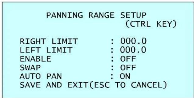
text_image
PANNING RANGE SETUP (CTRL KEY) RIGHT LIMIT : 000.0 LEFT LIMIT : 000.0 ENABLE : OFF SWAP : OFF AUTO PAN : ON SAVE AND EXIT(ESC TO CANCEL)- Place the dome camera under 90 degree vertically.
- Set "RIGHT LIMIT" by pushing the Joystick to the right.
- Set "LEFT LIMIT" by pushing the Joystick to the left.
- Set "ENABLE" to ON to use.
To exchange the right and the left limit, set "SWAP" to ON.
To apply limits on the auto pan (endless panning), set "AUTO PAN" to ON.
NOTE: When the flip mode is 90^ , 100^ , 110^ or 120^ and you moves over 90^ vertically, the panning range operates in opposite side.
- INITIALIZE DATA
INITIALIZE DATA
FACTORY DEFAULT
ERASE PROGRAMMED DATA
PRESET FOCUS DEFAULT
EXIT(ESC TO EXIT)
FACTORY DEFAULT
Select "FACTORY DEFAULT" to initialize the Data.
FACTORY DEFAULT
ARE YOU SURE?
CANCEL OK
ERASE PROGRAMMED DATA
Erase all stored data from the Flash-ROM of the selected dome camera. You will be asked to enter ON or OFF. If you desire to erase all data then select "ERASE" run, otherwise press the ESC key to exit without erasing. The erased data includes all stored data (Auto Scan, Preset, and Tour...) except origin offset.
The offset value is still valid after all data is erased. The offset value can be zero with default set of Offset origin menu.
ERASE PROGRAMMED DATA
| AUTO SCAN | : ON |
| PRESET | : ON |
| TOUR | : ON |
| PATTERN | : ON |
| AREA TITLE | : ON |
| PRIVACY ZONE | : ON |
| CAMERA | : ON |
| DOME SETUP | : ON |
| ERASE | |
| SAVE AND EXIT(ESC TO | |
PRESET FOCUS DEFAULT
This menu set the default mode of the focus when you save the Preset.
PRESET FOCUS DEFAULT
FOCUS : AUTO
SAVE AND EXIT(ESC TO CANCEL)
FOCUS : AUTO / MANUAL / ONE PUSH
- ORIGIN OFFSET
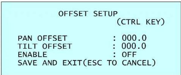
text_image
OFFSET SETUP (CTRL KEY) PAN OFFSET : 000.0 TILT OFFSET : 000.0 ENABLE : OFF SAVE AND EXIT(ESC TO CANCEL)This feature is useful to align a new dome camera exactly the same as the previously installed dome camera.
Dome camera's origin set and all data initialize option do not override offset values. Only the default set option in this menu will set the offset value to zero. This can be used to avoid ceiling obstructions.
• DOME RESET

text_image
DOME RESET ARE YOU SURE ? CANCEL OKThis feature is used to re-calibrate the orientation of a selected dome camera. Origin offset value is not affected by this function. (Offset is still valid after origin set.)
- SYSTEM MENU
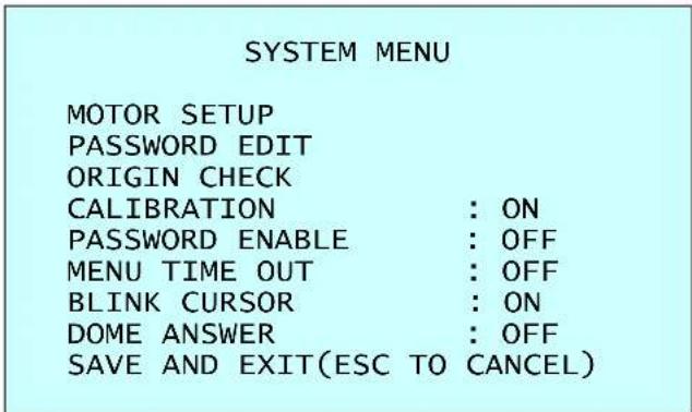
text_image
SYSTEM MENU MOTOR SETUP PASSWORD EDIT ORIGIN CHECK CALIBRATION : ON PASSWORD ENABLE : OFF MENU TIME OUT : OFF BLINK CURSOR : ON DOME ANSWER : OFF SAVE AND EXIT(ESC TO CANCEL)CALIBRATION : ON(Auto origin check) / OFF PASSWORD ENABLE : ON(requires the password to enter menu) / OFF MENU TIME OUT : ON(5mintues) / OFF(always menu display) BLINK CURSOR : ON / OFF(no blinking cursor) DOME ANSWER : ON / OFF(no acknowledge command from the dome) This option is helpful to escape the collision of the command using some DVR.
MOTOR SETUP
Motor Setup menu provides the pan and tilt speed of a camera. User can set the desired speed with pushing the Joystick to the left or right. During operation, pressing 153 + ON keys will change the speed to the SLOW mode and pressing 153 + OFF keys will change the speed to the Normal mode.
Press and hold the CTRL key and moving the Joystick will operate with the TURBO speed mode.
MOTOR SETUP
PROPOTIONAL P/T : ON P/T MODE : NORMAL
SAVE AND EXIT(ESC TO CANCEL)
PROPOTIONAL P/T : ON / OFF
P/T MODE : SLOW / NORMAL / TURBO
SLOW MAXIMUM SPEED : 40° /second
NORMAL MAXIMUM SPEED : 90° /second
TURBO MAXIMUM SPEED : 380° /second
PASSWORD EDIT
PASSWORD EDIT SETUP
(CTRL KEY)
INPUT PASSWORD
PASSWORD :
A B C D E F G H I J K L M N O P Q R S T U V W X Y Z 0 1 2 3 4 5 6 7 8 9 ( )
SAVE AND EXIT(ESC TO CANCEL)
You can change the password with 6-digit character in this menu.
The default password is 555555.
When the password enable is on, the input password window displays to enter the menu. At this time, move the cursor to the desired character by the Joystick and press the CTRL or IRIS Open key.
ORIGIN CHECK
When you find the wrong position of the dome during operation, execute this origin check and the dome camera will arrange the right position after the origin check operation.
ORIGIN CHECK
ARE YOU SURE ?
CANCEL
OK
Pressing 151 + ON keys will execute the origin check.
• SYSTEM INFORMATION
SYSTEM INFORMATION
CAMERA TYPE : xxxxx-Vx.xxxx
H/W VERSION : Vx.xx-xxxx
ROM VERSION : Vx.xxxxx
PROTOCOL : xxxx
BAUDRATE : 9600
EXIT(ESC TO EXIT)
The system information provides essential information about the dome camera if service is required. When you view this screen, you can determine the camera type, ROM version. The information on this screen cannot be modified.
3.13 Dome Communication
DOME COMMUNICATION SETUP
DOME ID : 001
PROTOCOL : AUTO
BAUDRATE : 9600
SAVE AND EXIT(ESC TO CANCEL)
To prevent damage, each dome camera must have a unique address (ID).
When installing multiple dome cameras using a multiplexer, it is suggested that the dome camera address match the multiplexer port number.
The factory default setting is 1.
Example: Port 1 = Dome 1, Port 2 = Dome 2 ... Port 16 = Dome 16. If more than 16 dome cameras are installed using two or more multiplexers, ID of the dome camera should be ID of MUX x No. of camera IN. (e.g. multiplexer ID= n, Camera IN= m then ID of Dome =16x(n-1)+m )
3.14 Function Run
This Function Run menu allows you to execute the function when you use a keyboard or a DVR without the function keys (Preset, Pattern, Tour and Scan).
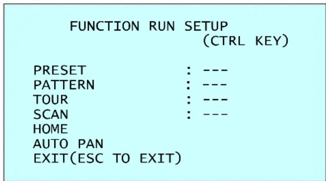
text_image
FUNCTION RUN SETUP (CTRL KEY) PRESET : --- PATTERN : --- TOUR : --- SCAN : --- HOME AUTO PAN EXIT(ESC TO EXIT)- Select the desired Function by pushing the Joystick up or down.
- Select the number by twist the Joystick in PRESET, PATTERN, TOUR, and SCAN.
- Press the CTRL or IRIS Open key to execute.
NOTE: To execute the function, you should save the function (PRESET, PATTERN, TOUR, and SCAN) first.
- HOME
Select "HOME" and press the CTRL key. Then dome camera goes to the default position to which the dome camera returns after an assigned period of inactivity passes. The default position may be a Preset, Tour, Pattern or no action.
- AUTO PAN
You can execute the endless auto pan which is to turn one direction continuously by select the Auto Pan.
3.15 Factory Setup
FACTORY SETUP
TOUR DWELL TIME : 03 SEC
TOUR DWELL TIME means the dwell time between Tours.
ANSWER DELAY means the response time of the dome and you don't need to change in normal condition.
Chapter 4 — Operation by Web Browser
The network camera can be used with Windows operating system and browsers.
The recommended browsers are Internet Explorer, Safari, Firefox, Opera and Google Chrome with Windows.
Note: To view streaming video in Microsoft Internet Explorer, set your browser to allow ActiveX controls.
4.1 Access from a browser
1) Start a browser (Internet Explorer).
2) Enter the IP address or host name of the network camera in the Location/Address field of your browser.
3) You can see a starting page. Click Live View or Setup to enter web page.
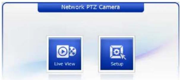
text_image
Network PTZ Camera Live View Setup4) The encoder's Live View page appears in your browser.
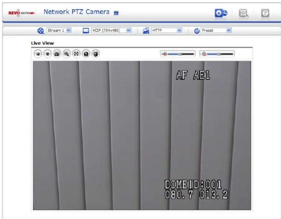
text_image
REVO SLUTEND Network PTZ Camera Stream 1 4CIF (704x480) HTTP Preset Live View AF AE1 DOMEID:001 080.7 013.24.2 Access from the internet
Access from the internet once connected, the network camera is accessible on your local network (LAN). To access the video encoder from the Internet you must configure your broadband router to allow incoming data traffic to the video encoder. To do this, enable the NAT traversal feature, which will attempt to automatically configure the router to allow access to the video encoder. This is enabled from Setup > System > Network > NAT Traversal.
For more information, please see NAT traversal (port mapping) for IPv4, on "4.5.5 System > 4) Network > ⑥ NAT Traversal".
4.3 Setting the admin password over a secure connection
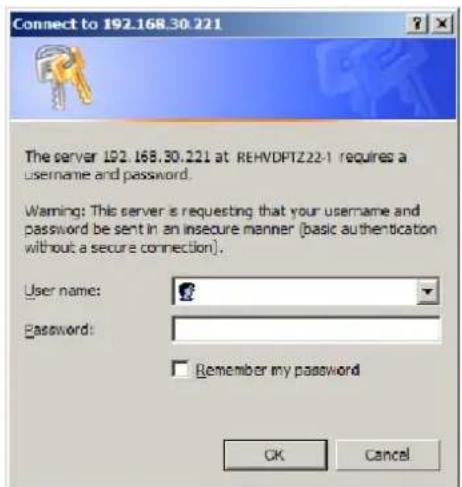
To gain access to the product, the password for the default administrator user must be set. This is done in the "Admin Password" dialog, which is displayed when the network camera is accessed for the setup at the first time. Enter your admin name and password, set by the administrator.
Note: The default administrator username and password is "admin". If the password is lost, the network camera must be reset to the factory default settings. Please see "4.8 Resetting to the factory default settings" for more details.
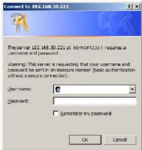
text_image
Connect to 192.168.30.221 The server L92.168.30.221 at REHVDPTZ22-1 requires a username and password. Warning: This server is requesting that your username and password be sent in an insecure manner (basic authentication without a secure connection). User name: Password: Remember my password OK CancelTo prevent network eavesdropping when setting the admin password, this can be done via an encrypted HTTPS connection, which requires an HTTPS certificate (see note below).
To set the password via a standard HTTP connection, enter it directly in the first dialog shown below. To set the password via an encrypted HTTPS connection, please see Setup > System > Security > HTTPS, on "4.5.5 System > 2) Security > ② HTTPS".
Note: HTTPS (Hypertext Transfer Protocol over SSL) is a protocol used to encrypt the traffic between web browsers and servers. The HTTPS certificate controls the encrypted exchange of information.
4.4 Live View Page
The live view page comes in seven screen modes like 704x576(480), 704x288(240), 352x288(240), 176x144(120), 640x480, 320x240 and 160x120. Users are allowed to select the most suitable one out of those modes. Please, adjust the mode in accordance with your PC specifications and monitoring purposes.
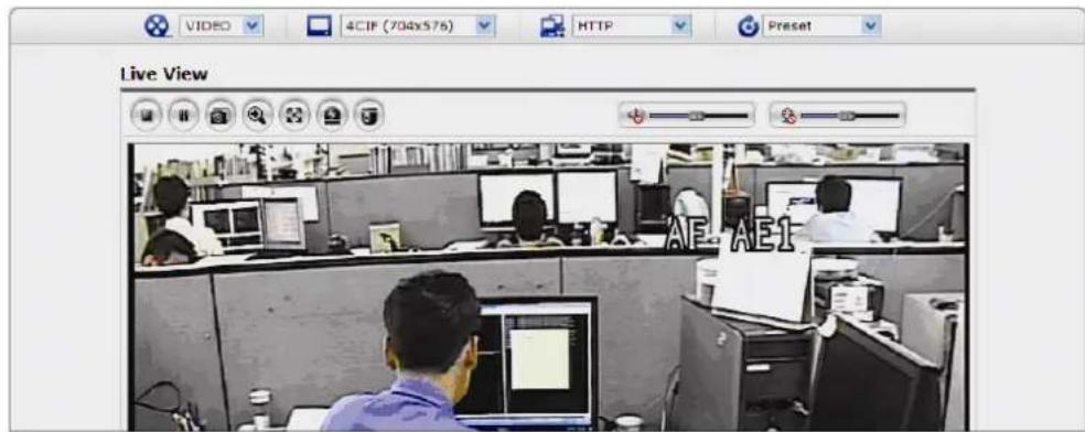
text_image
Live View VIDEO 4CIF (704x576) HTTP Preset AE AE11) General controls
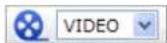
The video drop-down list allows you to select a customized or pre-programmed video stream on the live view page. Stream profiles are configured under Setup > Basic Configuration > Video & Image. Please see "4.5.1 Basic Configuration" for more information.

The resolution drop-down list allows you to select the most suitable one out of video resolutions to be displayed on live view page.
The protocol drop-down list allows you to select which combination of protocols and methods to use depends on your viewing requirements, and on the properties of your network.
The preset drop-down list allows you to select the preset number for the PTZ camera being used. This icon is inactivated if the PTZ settings are not set.
2) Control toolbar
The live viewer toolbar is available in the web browser page only. It displays the following buttons:

The Stop button stops the video stream being played. Pressing the key again toggles the start and stop. The Start button connects to the network camera or start playing a video stream.

The Pause button pause the video stream being played.

The Snapshot button takes a snapshot of the current image. The location where the image is saved can be specified.

The digital zoom activates a zoom-in or zoom-out function for video image on the live screen.

The Full Screen button causes the video image to fill the entire screen area. No other windows will be visible. Press the 'Esc' button on the computer keyboard to cancel full screen view.

The Manual Trigger button activates a pop-up window to manually start or stop the event.

The Camera Menu button activates a pop-up window for camera menu control.

The PTZ button activates a pop-up window for Pan, Tilt and Zoom control.

Use this scale to control the volume of the speakers.

Use this scale to control the volume of the microphone.

Use this scale to control the volume of the speakers and microphones.
3) Camera Menu controls
If the network camera has been appropriately configured, the Live View page displays the controls available for the OSD menu.
For more information, please see "Chapter 3 — Program and Operation".
4) Pan/Tilt/Zoom controls
If the network camera has been appropriately configured, the Live View page displays the controls available for the PTZ (Pan Tilt Zoom) or PT device installed. The administrator can enable/disable the controls for specified users.
Please see "4.6 PTZ Control" for more information.
5) Video and Audio Streams
The network camera provides several images and video stream formats. Your requirements and the properties of your network will determine the type you use.
The Live View page in the network camera provides access to H.264, MPEG-4 and Motion JPEG video streams, and to the list of available video streams. Other applications and clients can also access these video streams/images directly, without going via the Live View page.
4.5 Network Camera Setup
This section describes how to configure the network camera, and is intended for product Administrators, who have unrestricted access to all the Setup tools; and Operators, who have access to the settings for Basic, Live View, Video & Image, Audio, Event, and System Configuration.
You can configure the network camera by clicking Setup in the top right-hand corner of the Live View page. Click on this page to access the online help that explains the setup tools.
text_image
Connect to 192.168.30.221 The server 192.168.30.221 at REHVDPTZ22-1 requires a username and password. Warning: This server is requesting that your username and password be sent in an insecure manner (basic authentication without a secure connection). User name: Password: Remember my password OK CancelWhen accessing the network camera for the first time, the "Admin Password" dialog appears. Enter your admin name and password, set by the administrator.
Note: If the password is lost, the network camera must be reset to the factory default settings. Please see "4.8 Resetting to the Factory Default Settings".
4.5.1 Basic Configuration
1) Users
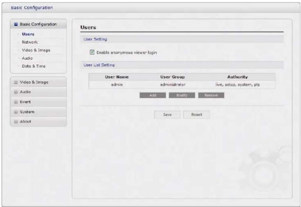
User access control is enabled by default. An administrator can set up other users, by giving these user names and passwords. It is also possible to allow anonymous viewer login, which means that anybody may access the Live View page, as described below:
text_image
Basic Configuration Basic Configuration Users Network Video & Image Audio Data & Time Video & Image Audio Event System About Users User Setting Enable anonymous viewer login User List Setting User Name User Group Authority admin administrator live, setup, system, ptz Add Modify Remove Save RoactThe user list displays the authorized users and user groups (levels):
| User Group Authority | |
| Guest | Provides the lowest level of access, which only allows access to the Live View page. |
| Operator | An operator can view the Live View page, create and modify events, and adjust certain other settings. Operators have no access to System Options. |
| Administrator | An administrator has unrestricted access to the Setup tools and can determine the registration of all other users. |
- Enable anonymous viewer login: Check the box to use the webcasting features. Refer to "4.5.2 Video & Image" for more details.
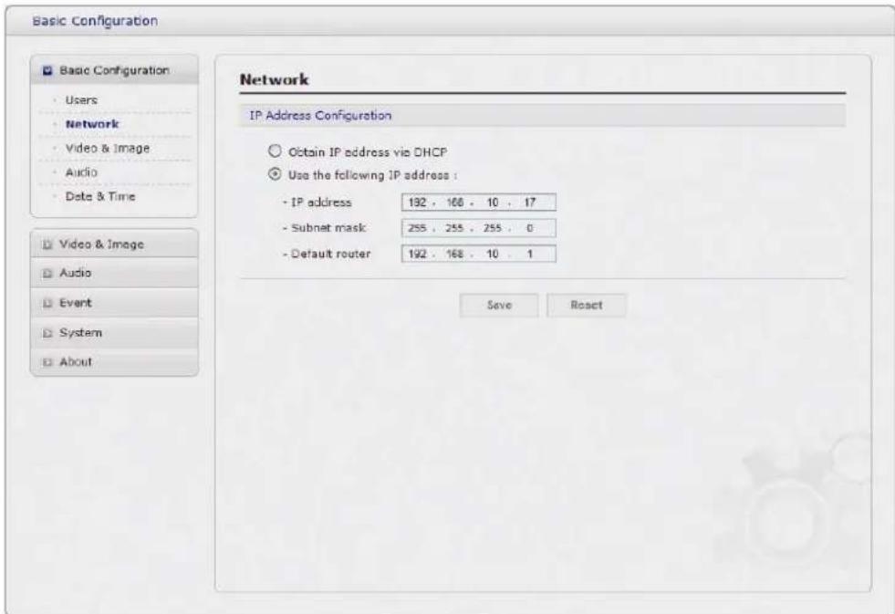
2) Network
The network camera support both IP version 4 and IP version 6. Both versions may be enabled simultaneously, and at least one version must always be enabled. When using IPv4, the IP address for the video encoder can be set automatically via DHCP, or a static IP address can be set manually. If IPv6 is enabled, the video encoders receive an IP address according to the configuration in the network router. There is also the option of using the Internet Dynamic DNS Service. For more information on setting the network, please see Setup > System > Network, on "4.5.5 System > 4) Network".
text_image
Basic Configuration Basic Configuration Users Network Video & Image Audio Date & Time Network IP Address Configuration Obtain IP address via DHCP Use the following IP address : - IP address 192 , 168 , 10 , 17 - Subnet mask 255 , 255 , 255 , 0 - Default router 192 , 168 , 10 , 1 Save Reset- Obtain IP address via DHCP: Dynamic Host Configuration Protocol (DHCP) is a protocol that lets network administrators centrally manage and automate the assignment of IP addresses on a network. DHCP is enabled by default. Although a DHCP server is mostly used to set an IP address dynamically, it is also possible to use it to set a static, known IP address for a particular MAC address.
-
Use the following IP address: To use a static IP address for the network camera, check the radio button and then make the following settings:
-
IP address - Specify a unique IP address for your network camera.
- Subnet mask - Specify the mask for the subnet the network camera is located on.
- Default router - Specify the IP address of the default router (gateway) used for connecting devices attached to different networks and network segments.
Notes:
- DHCP should only be enabled if using dynamic IP address notification, or if your DHCP server can update a DNS server, which then allows you to access the network camera by name (host name). If DHCP is enabled and you cannot access the unit, you may have to reset it to the factory default settings and then perform the installation again.
- The ARP/Ping service is automatically disabled two minutes after the unit is started, or as soon as an IP address is set.
- Pinging the unit is still possible when this service is disabled.
3) Video & Image
text_image
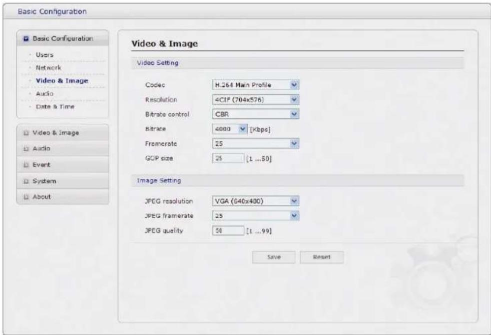
Basic Configuration Basic Configuration Users Network Video & Image Audio Data & Time Video & Image Audio Event System About Video & Image Video Setting Codec H.264 Main Profile Resolution 4CIF (704x576) Bitrate control CBR Bitrate 4000 [Kbps] Fromerate 25 GOP size 25 [1 ...50] Image Setting JPEG resolution VGA (640x400) JPEG framerate 25 JPEG quality 50 [1 ...99] Save Reset- Video Setting:
- Codec: The codec settings are separated into MPEG4 and H.264.
H.264 is also known as MPEG-4 Part 10. This is the new generation compression standard for digital video.
This function offers higher video resolution than Motion JPEG or MPEG-4 at the same bit rate and bandwidth, or the same quality video at a lower bit rate.
- Profile: There are 4 pre-programmed stream profiles available for quick set-up. Choose the form of video encoding you wish to use from the drop-down list:
* H.264 MP(Main Profile): Primarily for low-cost applications that requires additional error robustness, this profile is used rarely in videoconferencing and mobile applications, it does add additional error resilience tools to the Constrained Baseline Profile. The importance of this profile is fading after the Constrained Baseline Profile has been defined.
* H.264 BP(Base Profile): Originally intended as the mainstream consumer profile for broadcast and storage applications, the importance of this profile faded when the High profile was developed for those applications.
* MPEG4 SP(Simple Profile): Mostly aimed for use in situations where low bit rate and low resolution are mandated by other conditions of the applications, like network bandwidth, device size etc.
* MPEG4 ASP(Advanced Simple Profile): Its notable technical features relative to the Simple Profile, which is roughly similar to H.263, including "MPEG"-style quantization, interlaced video, B pictures (also known as B Frames), Quarter Pixel motion compensation (Qpel), Global motion compensation (GMC).
- Resolution: It enables users to determine a basic screen size when having an access through the Web Browser or PC program. The screen size control comes in seven modes like 4CIF(704x576(480)), 2CIF(704x288(240)), CIF(352x288(240)), QCIF(176x144(120)), VGA(640x480), QVGA(320x240), and QQVGA(160x120). Users can reset the selected screen size anytime while monitoring the screen on a real-time basis.
- Bitrate control: Limiting the maximum bit rate helps control the bandwidth used by the H.264 or MPEG-4 video stream. Leaving the Maximum bit rate as unlimited maintains consistently good image quality but increases bandwidth usage when there is more activity in the image. Limiting the bit rate to a defined value prevents excessive bandwidth usage, but images are lost when the limit is exceeded.
Note that the maximum bit rate can be used for both variable and constant bit rates.
The bit rate can be set as Variable Bit Rate (VBR) or Constant Bit Rate (CBR). VBR adjusts the bit rate according to the image complexity, using up bandwidth for increased activity in the image, and less for lower activity in the monitored area.
CBR allows you to set a fixed target bitrate that consumes a predictable amount of bandwidth. As the bit rate would usually need to increase for increased image activity, but in this case cannot, the frame rate and image quality are affected negatively. To partly compensate for this, it is possible to prioritize either the frame rate or the image quality whenever the bit rate needs to be increased. Not setting a priority means the frame rate and image quality are equally affected.
- Compression: When it is necessary to adjust a smooth transmission status according to network situations, users can increase the compressibility to carry out the network transmission stably. On the other hand, when it is necessary to maintain a detailed monitoring screen by enhancing the image quality, users can do so by decreasing the compressibility. In ease case, please adjust this function according to the network status and monitoring purposes. The default is 2000(Kbps).
- Frame rate: Upon the real-time play, users should select a frame refresh rate per second. If the rate is high, the image will become smooth. On the other hand, if the rate is low, the image will not be natural but it can reduce a network load.
- GOP size: Select the GOP(Group of Picture) size. If users want to have a high quality of fast image one by one, please decrease the value. For the purpose of general monitoring, please do not change a basic value. Such act may cause a problem to the system performance. For the details of GOP setting, please contact the service center.
- Image Setting: Sometimes the image size is large due to low light or complex scenery. Adjusting the frame rate and quality helps to control the bandwidth and storage used by the Motion JPEG video stream in these situations. Limiting the frame rate and quality optimizes bandwidth and storage usage, but may give poor image quality. To prevent increased bandwidth and storage usage, the Resolution, Frame rate, and Frame Quality should be set to an optimal value.
- JPEG resolution: Same as the video settings.
- JPEG frame rate: Same as the video settings.
- JPEG quality: Select the picture quality. If users want to have a high quality of fast image one by one, please decrease the value. For the purpose of general monitoring, please do not change a basic value. Such act may cause a problem to the system performance.
When satisfied with the settings, click Save, or click Reset to revert to previously saved settings.
4) Audio
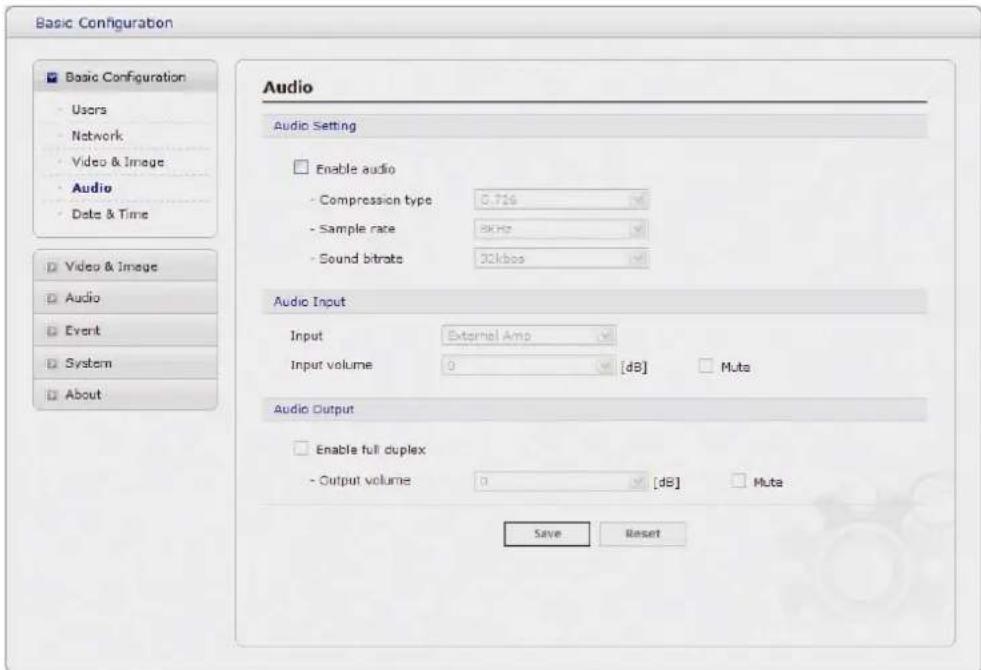
text_image
Basic Configuration Basic Configuration Users Network Video & Image Audio Date & Time Video & Image Audio Event System About Audio Audio Setting Enable audio - Compression type: 0.716 - Sample rate: 8kHz - Sound bitrate: 30kbps Audio Input Input External Amp Input volume 0 [dB] Muts Audio Output Enable full duplex - Output volume: 0 [dB] Muts Save ResetThe network camera can transmit audio to other clients using an external microphone and can play audio received from other clients by attaching a speaker. The Setup page has an additional menu item called Audio, which allows different audio configurations, such as, full duplex, and simplex.
- Audio Setting:
- Enable audio: Check the box to enable audio in the video stream.
- Compression type: Select the desired audio Compression format, G.711.
- Sample rate: Select the required Sample rate (number of times per second the sound is sampled). The higher the sample rate, the better the audio quality and the greater the bandwidth required.
- Sound bitrate: Depending on the selected encoding, set the desired audio quality (bitrate). The settings affect the available bandwidth and the required audio quality.
- Audio Input:
Audio from an external line source can be connected to the RCA Jack I/O of the network camera.
- Input volume: If there are problems with the sound input being too low or high, it is possible to adjust the input gain for the microphone attached to the network camera.
- Audio Output:
- Enable full duplex: Check the box to enable Full Duplex mode. It means that you can transmit and receive audio (talk and listen) at the same time, without having to use any of the controls. This is just like having a telephone conversation.
This mode requires that the client PC has a sound card with support for full-duplex audio.
Uncheck the box enable Simplex mode. The simplex mode only transmits audio from the network camera to any web client. It does not receive audio from other web clients.
- Output volume: If the sound from the speaker is too low or high it is possible to adjust the output gain for the active speaker attached to the network camera.
When satisfied with the settings, click Save, or click Reset to revert to previously saved settings.
5) Date & Time
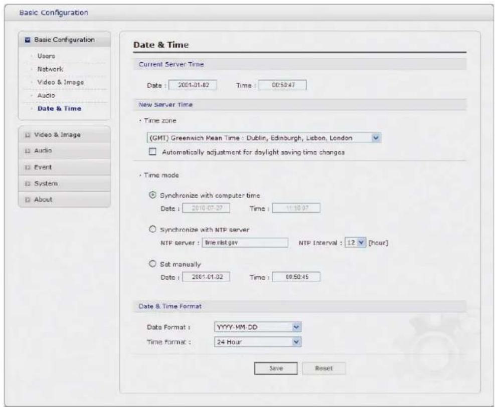
text_image
Basic Configuration Basic Configuration Users Network Video & Image Audio Date & Time Video & Image Audio Event System About Date & Time Current Server Time Date : 2001-01-02 Time : 00:50:47 New Server Time • Time zone (GMT) Greenwich Mean Time : Dublin, Edinburgh, Lisbon, London • Automatically adjustment for daylight saving time changes • Time mode ○ Synchronize with computer time Date : 2010-07-27 Time : 11:30:07 ○ Synchronize with NTP server NTP server : time.nlat.gov NTP Interval : 12 [hour] ○ Sat manually Date : 2001-01-02 Time : 00:50:45 Date & Time Format Data Format : YYYY-MM-DD Time Format : 24 Hour Save Reset- Current Server Time:
It displays the current date and time (24h clock). The time can be displayed in 12h clock format in the overlay (see below).
- New Server Time:
Select your time zone from the drop-down list. If you want the server clock to automatically adjust for daylight savings time, select the "Automatically adjustment for daylight saving time changes".
From the Time Mode section, select the preferred method to use for setting the time:
- Synchronize with computer time: sets the time from the clock on your computer.
- Synchronize with NTP Server: the video encoder will obtain the time from an NTP server every 60 minutes.
- Set manually: this option allows you to manually set the time and date.
4.5.2 Video & Image
1) Basic
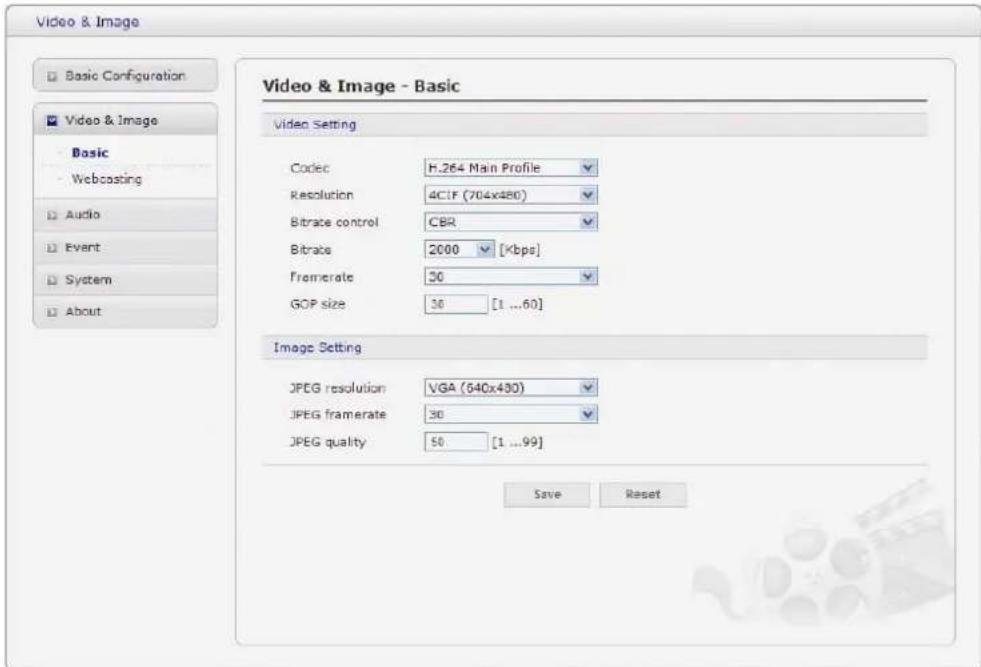
text_image
Video & Image Basic Configuration Video & Image Basic - Webcasting Audio Event System About Video & Image - Basic Video Setting Codec H.264 Main Profile Resolution 4CIF (704x480) Bitrate control CBR Bitrate 2000 [Xbps] Fremerate 30 GOP size 30 [1 ...60] Image Setting JPEG resolution VGA (540x430) JPEG framerate 30 JPEG quality 50 [1 ...99] Save ResetRefer to "4.5.1 Basic Configuration > 3) Video & Image" for more details.
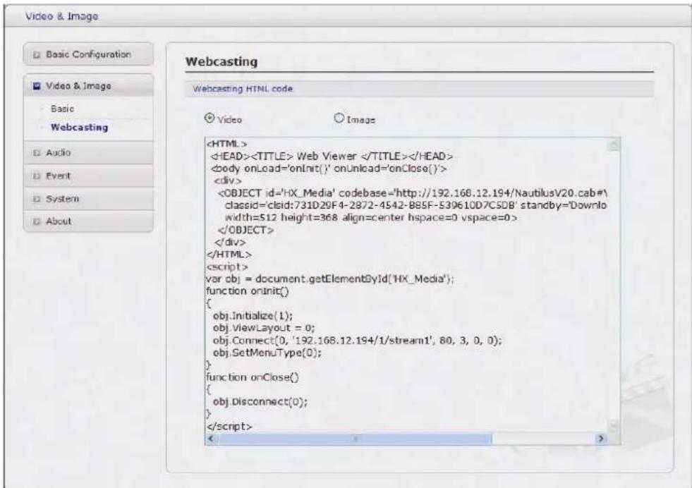
2) Webcasting – Channel1
The network camera can stream live video to a website. Copy the HTML code generated on the screen and paste it in page code of the website you want to display live video.