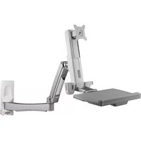
A-STSWW-A - Poste de travail assis-debout mural Atdec - Free user manual and instructions
Find the device manual for free A-STSWW-A Atdec in PDF.


| Product Type | Monitor Arm |
| Brand | Atdec |
| Model | A-STSWW-A |
| VESA Compatibility | 75x75mm, 100x100mm |
| Weight Capacity | 8 kg (17.6 lbs) |
| Tilt Range | -5° to +15° |
| Swivel Range | ±90° |
| Rotation | 360° |
| Material | Aluminum, Steel |
| Color | Black |
| Mounting Options | Desk clamp or grommet mount |
| Height Adjustment | Yes (gas spring) |
| Cable Management | Built-in cable channel |
| Maximum Reach | 480 mm (18.9 in) |
| Product Weight | 2.5 kg (5.5 lbs) |
| Power Supply | Not required (passive) |
| Cleaning Instructions | Wipe with a soft, dry cloth |
| Safety Warning | Do not exceed weight capacity; ensure secure installation |
| Spare Parts Availability | VESA plates, gas springs, and mounting hardware |
| Environment | Indoor use only |
| Warranty | 2 years |
Frequently Asked Questions - A-STSWW-A Atdec
User questions about A-STSWW-A Atdec
0 question about this device. Answer the ones you know or ask your own.
Ask a new question about this device
Download the instructions for your Poste de travail assis-debout mural in PDF format for free! Find your manual A-STSWW-A - Atdec and take your electronic device back in hand. On this page are published all the documents necessary for the use of your device. A-STSWW-A by Atdec.
USER MANUAL A-STSWW-A Atdec
Sit-to-Stand Workstation - Antimicrobial
Wall Mounted

natural_image
Line drawing of a mechanical arm with adjustable legs and a flat base (no text or symbols)Component Checklist

natural_image
Technical line drawing of a mechanical lever assembly (no text or symbols)
Lower Arm Upper Arm
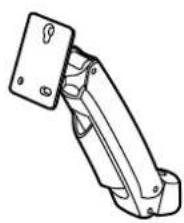
natural_image
Technical line drawing of a mechanical bracket or clamp assembly (no text or symbols)
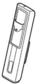

Vertical Screen
Slider

natural_image
Line drawing of a mechanical clamp or bracket device (no text or symbols)Keyboard Tray Tilt Head


Tools Required
- 8mm wrench
- Drill
- 10mm masonry bit
- 4.5mm drill bit
- Ratchet
- Spirit Level
- Stud Finder
- Pencil
Wall Mounting Hardware
F

Coach
Screw (x6)
G

Nylon
Anchor (x6)
Hardware
HJKL

M

5mm Allen 6
N

m = 311

AlkenDrive

Plastic Washer (x1)

Metal Washer (x1)
O

P

QR

M6X10 (x3)
s

M6X8 (x1) M4x10 (x4) M6X12 5x4) M8X20 (x1)
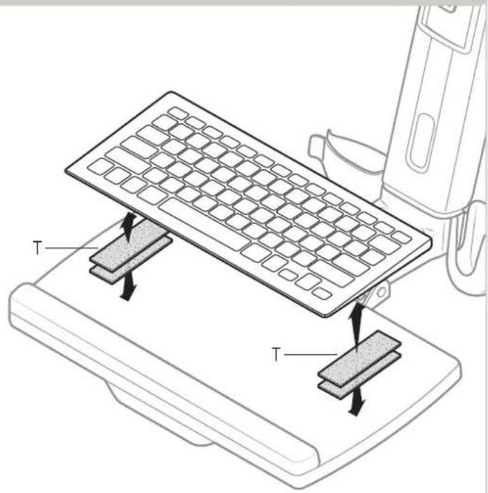
T


Velcro
IMPORTANT INFORMATION
! IMPORTANT - Install as per Installation Instructions
! The manufacturer accepts no responsibility for incorrect installation.
! This product supports a maximum load 8Kg (17.6lbs.)
! The wall mount can be installed on vertical, flat, solid concrete or brick walls, or timber stud walls only.
! Thewallshouldbestrongenoughtosustainaweightofatleastfourtimesthatofthedisplayandwallmountbracketcombined. If in doubt, consult a structural engineer.
! Checkwallanchorsandscrewsevery3monthsfromthe timeofinstallationtoensuretheworkstationisfirmlyfixedtothewall.
! Tighten all screws (do not exert excessive force to avoid breaking the screws or damaging their thread)
Step 1. Check Components
Check that you have received all parts against the Component Checklist.
Step 2. Option A - Masonry or cement wall installation
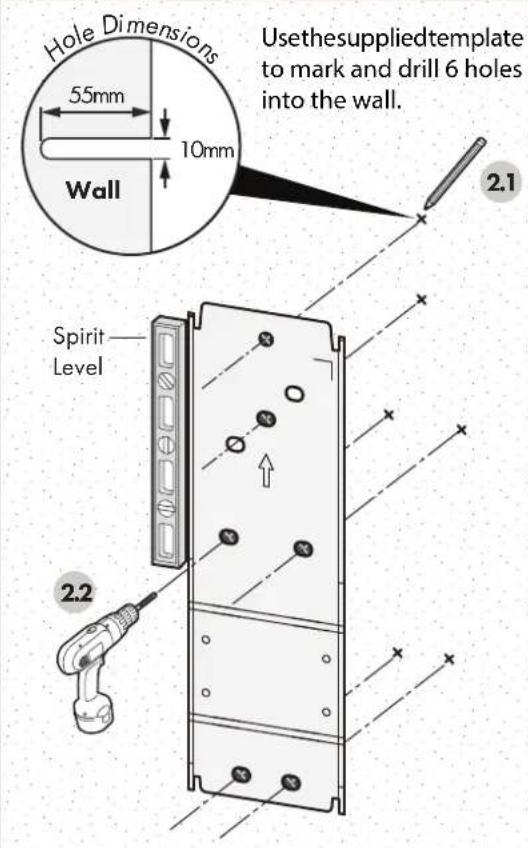
Note: For optimum performance, use a spirit level to ensure straight installation.

Tip: Screw in the top coach screw first.
Step 2. Option B - Stud wall installation
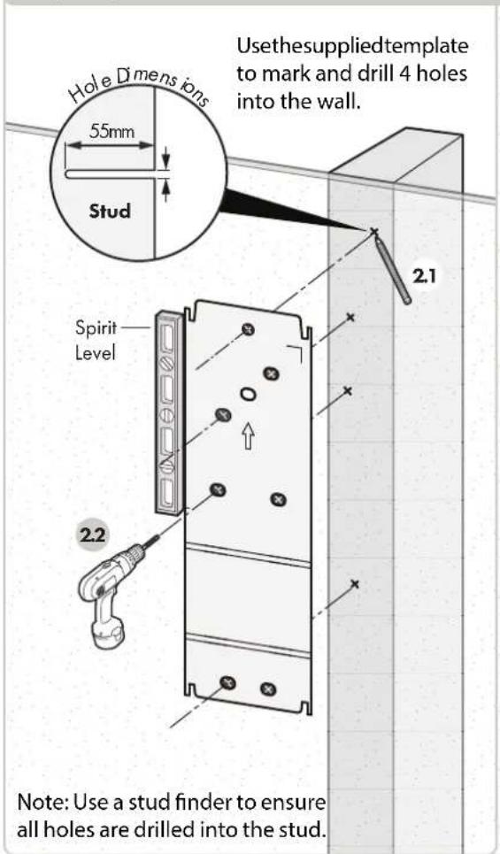


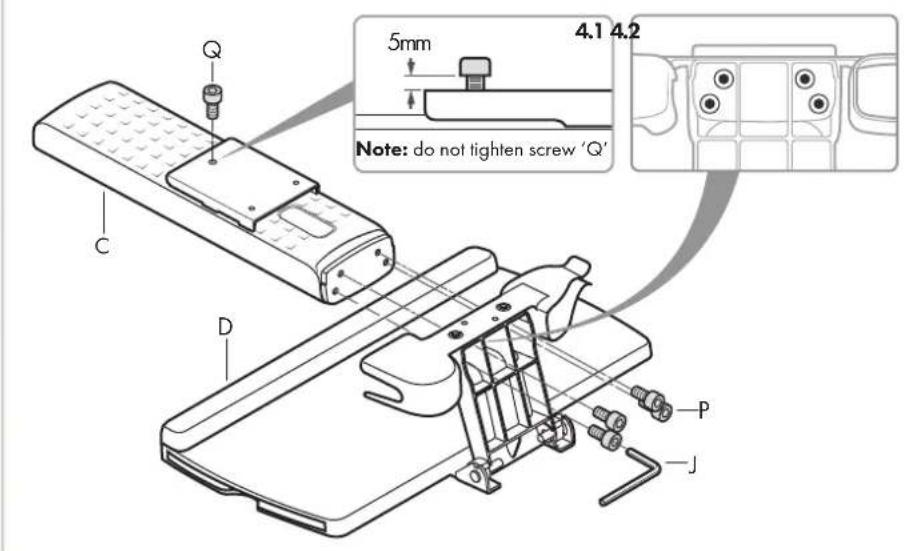
Step 4. Assemble slider to keyboard trayStep 3. Assemble upper arm
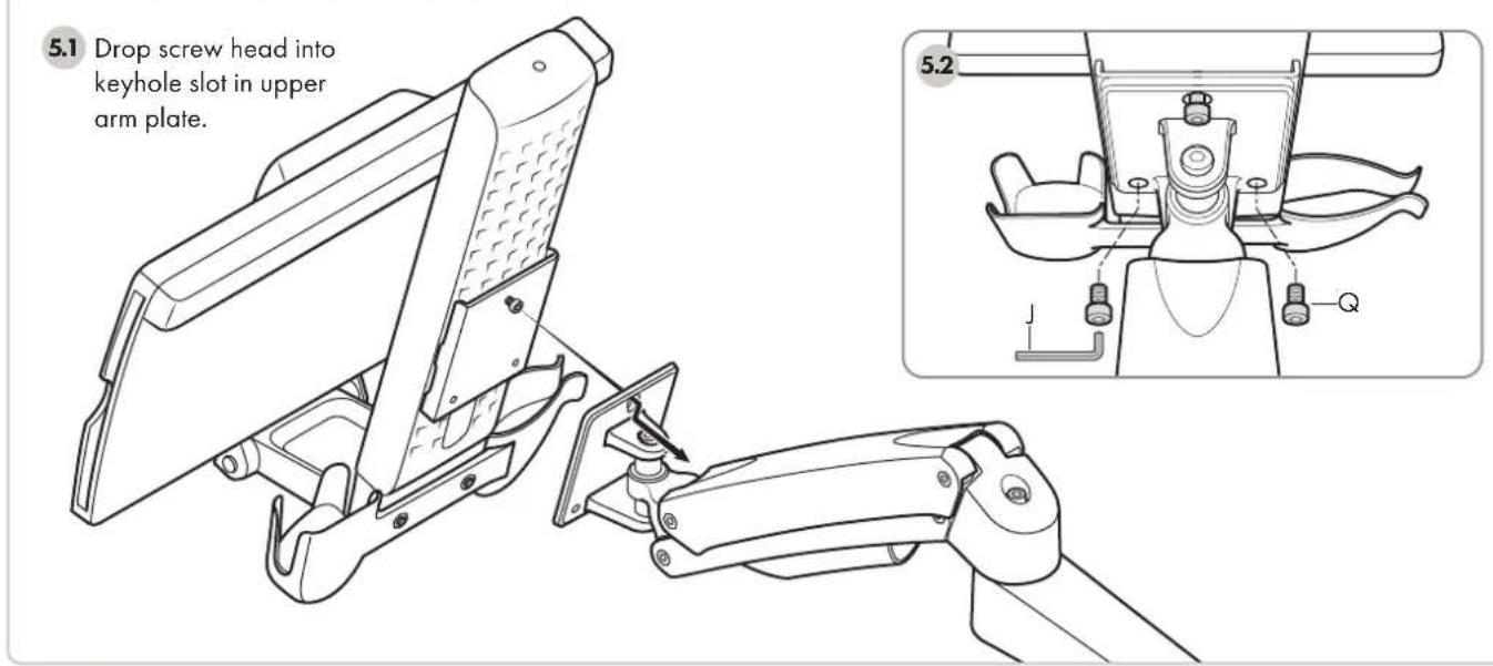
Step 5. Assemble slider to keyboard tray
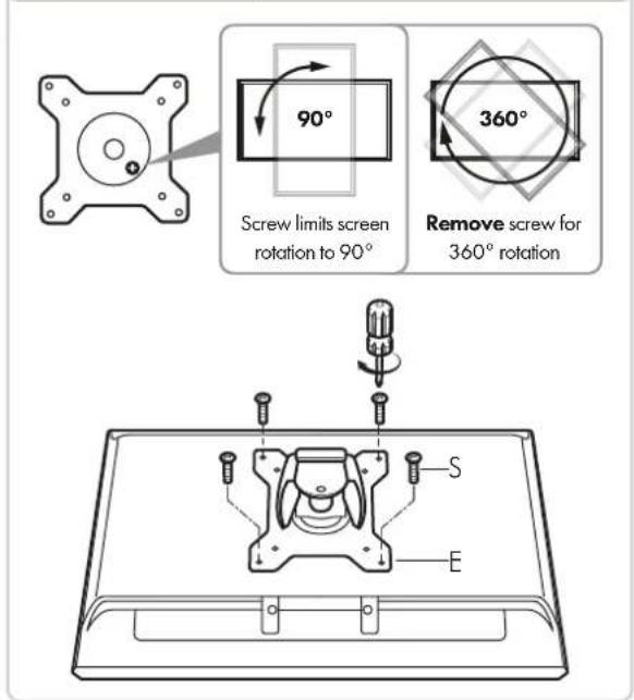
Step 6. Attach tilting head to screen
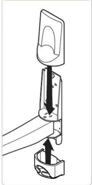
Step 7. Attach screen to arm Step 8. Replace covers

natural_image
Technical line drawing of a mechanical assembly with a lever and base mount (no text or symbols)Adjusting
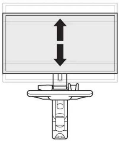
Screen Height Tension
natural_image
Diagram of a mechanical device with two vertical arrows pointing up and down, mounted on a base (no text or symbols)
Tension Adjustment Points

Screen Tilt Tension

Keyboard Tray Storage
The keyboard tray can be folded away for storage.

natural_image
Mechanical assembly diagram showing a 90-degree angle measurement on a bracket (no text or symbols present)Note: Supplied velcro strips secure the keyboard when stowed.
Arm Rotation Joint Tension


Note: Arm must be in highest position to access tension adjustment point.

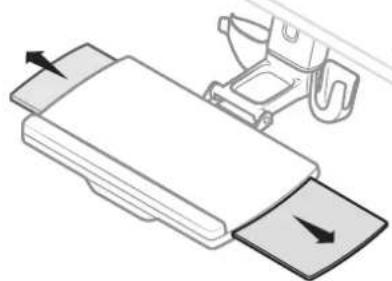
Mouse Tray PositionArm Height Tension
natural_image
Diagram of a mechanical device with a lever and handle, showing no text or symbolsThe mouse tray can be positioned on the left or right of the keyboard tray.
Cable Management. Route cables through arm.
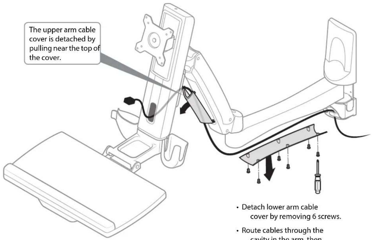
Note: Ensure there is sufficient slack in the cables to accommodate the workstation's range of movement.
- Detach lower arm cable cover by removing 6 screws.
- Route cables through the cavity in the arm, then reattach the cover.
Secure Keyboard Attach velcro to keyboard and tray Cleaning


flowchart
graph TD
    A["OR Gate"] --> B["Down Arrow"]
    B --> C["Up Up"]
    C --> D["Made in Taiwan"]
    E["OR Gate"] --> F["Down Arrow"]
    F --> G["Up Down"]
    H["Stud Wall Drilling Template"] --> I["Only drill holes marked with an 'X'"]
    J["OR Gate"] --> K["Down Arrow"]
    K --> L["Up Up"]

Brand : Atdec
Model : A-STSWW-A
Category : Poste de travail assis-debout mural