OnCell G3150-T - Uncategorized Moxa - Free user manual and instructions
Find the device manual for free OnCell G3150-T Moxa in PDF.


| Product Type | Cellular IP Gateway |
| Model | OnCell G3150-T |
| Brand | Moxa |
| Cellular Standards | Quad-band GSM/GPRS/EDGE 850/900/1800/1900 MHz; Five-band UMTS/HSPA 800/850/AWS/1900/2100 MHz (HSPA models) |
| Serial Interface | 1 RS-232 (DB9 male) + 1 RS-422/485 (5-pin terminal block) |
| Ethernet Interface | 1 RJ45, 10/100 Mbps, auto-negotiation |
| Power Input | Dual DC inputs, 12 to 48 VDC |
| Power Consumption | 585 to 900 mA peak @ 12 VDC |
| Operating Temperature | -30 to 55°C (standard); -30 to 70°C (wide temp models) |
| Storage Temperature | -40 to 75°C |
| Relative Humidity | 5 to 95% (non-condensing) |
| Weight | Approx. 500 g |
| Dimensions (L x W x H) | Approx. 100 x 80 x 30 mm |
| Operation Modes | Real COM, Reverse Real COM, RFC2217, TCP Server, TCP Client, UDP, Ethernet Modem, SMS Tunnel, Virtual Modem |
| Secure Modes | Secure Real COM, Secure Reverse Real COM, Secure TCP Client, Secure TCP Server (SSL) |
| Data Buffering | 256 KB per port, prevents data loss during communication disruption |
| Digital I/O | 2 digital inputs (isolated), 1 relay output (1A @ 24 VDC) |
| SIM Card | 1 slot, 3V SIM, internal installation |
| Warranty | 5 years |
| Regulatory Approvals | CE, FCC Class A, UL60950-1 |
Frequently Asked Questions - OnCell G3150-T Moxa
User questions about OnCell G3150-T Moxa
0 question about this device. Answer the ones you know or ask your own.
Ask a new question about this device
Download the instructions for your Uncategorized in PDF format for free! Find your manual OnCell G3150-T - Moxa and take your electronic device back in hand. On this page are published all the documents necessary for the use of your device. OnCell G3150-T by Moxa.
USER MANUAL OnCell G3150-T Moxa
OnCell G3100 Series User's Manual
Edition 8.1, August 2016
www.moxa.com/product
MOXA®
© 2016 Moxa Inc. All rights reserved.
OnCell G3100 Series User's Manual
The software described in this manual is furnished under a license agreement and may be used only in accordance with the terms of that agreement.
Copyright Notice
© 2016 Moxa Inc. All rights reserved.
Trademarks
The MOXA logo is a registered trademark of Moxa Inc.
All other trademarks or registered marks in this manual belong to their respective manufacturers.
Disclaimer
Information in this document is subject to change without notice and does not represent a commitment on the part of Moxa.
Moxa provides this document as is, without warranty of any kind, either expressed or implied, including, but not limited to, its particular purpose. Moxa reserves the right to make improvements and/or changes to this manual, or to the products and/or the programs described in this manual, at any time.
Information provided in this manual is intended to be accurate and reliable. However, Moxa assumes no responsibility for its use, or for any infringements on the rights of third parties that may result from its use.
This product might include unintentional technical or typographical errors. Changes are periodically made to the information herein to correct such errors, and these changes are incorporated into new editions of the publication.
Technical Support Contact Information
www.moxa.com/support
Moxa Americas
Toll-free: 1-888-669-2872
Tel: +1-714-528-6777
Fax: +1-714-528-6778
Moxa Europe
Tel: +49-89-3 70 03 99-0
Fax: +49-89-3 70 03 99-99
Moxa India
Tel: +91-80-4172-9088
Fax: +91-80-4132-1045
Moxa China (Shanghai office)
Toll-free: 800-820-5036
Tel: +86-21-5258-9955
Fax: +86-21-5258-5505
Moxa Asia-Pacific
Product Features 1-3
Product Specifications 1-3
DoC (Declaration of Conformity)....1-5
Federal Communication Commission Interference Statement 1-5
OnCell G3100 Series Supporting Information 1-5
FCC Radiation Exposure Statement....1-6
2. Getting Started 2-1
Panel Layout 2-2
Connecting the Hardware 2-3
Wiring Requirements 2-4
SIM Card Installation 2-4
Connecting the Power 2-5
Connecting the I/O Port 2-5
Connecting to the Network 2-6
Connecting to a Serial Device 2-6
Connecting to the Ethernet Device....2-6
Adjustable Pull High/Low Resistors for the RS-485 Port (for RS-232/422/485 models) 2-6
LED Indicators 2-8
Reset Button 2-9
3. Initial IP Address Configuration 3-1
Static and Dynamic IP Addresses....3-2
Factory Default IP Address....3-2
Configuration Options....3-2
OnCell Search Utility 3-2
Web Console 3-2
ARP 3-2
Telnet Console 3-3
Serial Console 3-7
4. Introducing Serial Port Operation Modes 4-1
Overview 4-2
Device Control Applications....4-2
Real COM and Secure Real COM Modes 4-2
Types of Real COM Connection 4-3
Reverse Real COM and Secure Reverse Real COM Modes 4-4
Types of Reverse Real COM Connection 4-4
RFC 2217 Mode....4-5
Socket Applications 4-5
TCP Server and Secure TCP Server Modes 4-5
Types of TCP Server Connection 4-6
TCP Client and Secure TCP Client Modes....4-7
Types of TCP Client Connection 4-7
UDP Mode 4-8
Types of UDP Connection....4-8
Ethernet Modem Mode....4-9
SMS Tunnel Mode 4-9
Disabled Mode 4-9
5. Introducing OnCell Central Manager and Ethernet Operation Modes 5-1
OnCell Central Management Software 5-2
OnCell Central Serial Device Connection 5-2
OnCell Central Ethernet Device Connection 5-3
Cellular-Enabling Ethernet Device 5-3
Virtual Modem Mode 5-4
6. Using the Web Console.... 6-1
Using Your Web Browser....6-2
Browser Cookie Settings....6-2
Trusted Site Settings 6-3
Opening the Web Console....6-4
Web Console Navigation 6-5
Basic Settings 6-6
Server Settings 6-6
Time Settings 6-6
Network Settings....6-7
Basic Network Settings 6-7
DNS Settings 6-9
Advanced Network Settings 6-9
Auto IP Report Settings....6-10
GuaranLink Settings....6-11
Overview....6-11
Background 6-11
Common Settings....6-11
GuaranLink Check Settings 6-12
- Cellular Network Settings 7-1
GSM GPRS Settings (For OnCell G3110 and G3150) 7-2
Cellular Setting (OnCell G3110-HSPA and OnCell G3150-HSPA)....7-2
GSM or GSM (CSD) Operation Mode 7-3
GPRS or GPRS/EDGE/UMTS/HSPA Operation Mode 7-4
SMS Operation mode 7-5
Virtual Modem Operation mode....7-6
- Configuring Serial Port Operation Modes 8-1
Port Setting Basics....8-2
Device Control Applications....8-2
Real COM Mode 8-2
Reverse Real COM Mode 8-5
RFC2217 Mode....8-7
Socket Applications 8-9
TCP Server Mode....8-9
TCP Client Mode 8-11
UDP Mode 8-14
Ethernet Modem Mode....8-15
SMS Tunnel Mode 8-18
Disabled Mode 8-20
- Configuring the Cellular-Enabling Ethernet Device 9-1
Host to OnCell via Cellular 9-2
OnCell to Host via Cellular 9-3
- Configuring Virtual Modem Mode 10-1
OnCell G3100 Web Settings 10-2
Installing Windows Driver Manager....10-2
Using Windows Driver Manager 10-5
Using PComm for Data Transmission....10-6
CSD via AT command....10-7
SMS via AT command....10-8
GPRS via AT command 10-9
GPRS via Windows Dial-up Network 10-9
- Understanding and Configuring a VPN 11-1
What Are VPNs? 11-2
OnCell VPN Specifications 11-2
OnCell VPN Web Console Settings 11-3
Manual Key/ESP 11-3
Configuration....11-3
Remote Network 11-3
Local Network....11-4
Incoming Security Settings....11-4
Outgoing Security Settings....11-4
ISAKMP/PSK 11-5
Configuration....11-5
Remote Network 11-5
ISAKMP (Key Management) 11-6
Local Identity 11-6
ISAKMP phase 1....11-6
ISAKMP phase 2....11-6
Advanced settings 11-6
VPN system log events and error codes....11-7
- Additional Serial Port Settings 12-1
Port Communication Parameters....12-2
Serial Parameters 12-2
Port Data Buffering/Log 12-3
Port Chipher Settings 12-3
- System Management Settings 13-1
Misc. Network Settings 13-2
Accessible IP List 13-2
SNMP Agent Settings....13-3
DDNS 13-4
Host Table 13-4
System Log Settings....13-5
Virtual Server Settings....13-6
Auto Warning Settings....13-7
Event Settings 13-7
Serial Event Settings 13-8
E-mail Alert 13-9
SNMP Trap....13-9
SMS Alert 13-10
Customized SMS 13-10
Remote Management 13-10
Remote SMS Control.... 13-10
Manual SMS....13-11
Remote Caller ID....13-12
Maintenance 13-12
Console Settings 13-12
Ping....13-12
Firmware Upgrade.... 13-13
Configuration Import/Export 13-13
Load Factory Defaults 13-14
Change Password 13-14
Certificate....13-15
Ethernet SSL Certificate Import 13-15
Certificate/Key Delete 13-15
System Monitoring 13-15
Serial to Network Connections 13-15
Serial Port Status....13-16
Serial Port Error Count 13-16
Serial Port Settings....13-16
Chipher Usage Status 13-16
System Status....13-17
Serial Data Log 13-17
System Log 13-17
Dout State....13-18
DIN and Power Status....13-18
Network Status 13-19
Network Connections.... 13-19
Network Statistics 13-19
Routing 13-19
DHCP Client List 13-20
Internet Sessions List 13-20
Save Configuration 13-21
Restart 13-21
Restart System 13-21
Restart Ports....13-21
- Software Installation/Configuration 14-1
Overview 14-2
Windows Driver Manager 14-2
Installing Windows Driver Manager....14-2
Using Windows Driver Manager....14-5
OnCell Search Utility 14-13
Installing OnCell Search Utility 14-13
Configuring OnCell Search Utility 14-15
Moxa OnCell Linux Real TTY Driver 14-18
Basic Procedure 14-18
Hardware Setup 14-19
Installing Linux Real TTY Driver Files....14-19
Mapping TTY Ports 14-19
Removing Mapped TTY Ports 14-20
Removing Linux Driver Files.... 14-20
Moxa OnCell UNIX Fixed TTY Driver 14-20
Installing the UNIX Driver....14-20
Configuring the UNIX Driver 14-21
A. Pinouts and Cable Wiring A-1
Port Pinout Diagrams ......A-2
RS-232 (male DB9) Pinouts....A-2
4W/2W RS-485/RS-422 (Terminal Block) Pinouts ......A-2
Power Input and Relay Output Pinouts ......A-2
Cable Wiring Diagrams....A-3
Serial Cables ...... A-3
Pin Assignments for DB9 and DB25 Connectors....A-4
B. RFC2217......B-1
C. Dynamic Domain Name Server ...... C-1
Overview C-1
Configuration C-2
D. Well Known Port Numbers ...... D-1
E. Auto IP Report Protocol ...... E-1
F. GSM Alphabet.... F-1
G. Default Settings ...... G-1
The OnCell G3100 series of cellular IP gateways have many exceptional features. Cellular IP gateways give you an easy way to connect your serial and Ethernet devices to cellular mobile networks. Different models of the OnCell G3100 series differ from their supported cellular standard and serial interface type. For example, OnCell G3110 is a GRPS IP gateway with RS-232 serial interface while OnCell G3150-HSPA is a HSPA IP gateway with RS-232/422/485 serial interface.
The following topics are covered in this chapter:
Overview
□ Package Checklist
□ Product Features
□ Product Specifications
☐ DoC (Declaration of Conformity)
➢ Federal Communication Commission Interference Statement
OnCell G3100 Series Supporting Information
➢ FCC Radiation Exposure Statement
Overview
The OnCell G3100, which can be used to connect any serial device and Ethernet device to a cellular network, supports a number of different operation modes. The OnCell COM driver turns the OnCell G3100's serial ports into virtual COM ports that allow you to communicate with your serial and Ethernet devices remotely over the cellular network. The OnCell G3100 comes pre-installed with the TCP/IP protocol suite to transmit data back and forth between the serial and Ethernet device and GPRS/EDGE or UMTS/HSPA TCP/IP network.
The OnCell G3100 functions as a router to achieve Ethernet to cellular connectivity. All Ethernet devices connected to the OnCell's LAN port are hidden from public view via the OnCell's NAT function.
The OnCell G3100 also supports Secure TCP Server, Secure TCP Client, Secure Real COM, and Secure Reverse Real COM modes for security critical applications, such as access control, and remote site management.
The OnCell G3100 also comes with a built-in relay output that can be configured to indicate the priority of events when notifying or warning engineers in the field, and the two digital inputs allow you to connect basic I/O devices, such as sensors, to the cellular network.
For some applications, serial data must be delivered reliably even if communication is disrupted. The OnCell G3100 provides a powerful function to ensure that serial data is buffered in case of a communication failure. When a communication failure occurs, the serial data is buffered in the OnCell G3100 until communication is resumed, at which point the buffered data is sent to its destination.
Package Checklist
Each OnCell G3100 serial and Ethernet cellular IP gateway is shipped in a separate box with standard accessories. In addition, several optional accessories can be ordered separately. When you receive your shipment, please check the contents of the box carefully, and notify your Moxa sales representative if any of the items are missing or appear to be damaged.
OnCell G3100 Series cellular IP gateways are shipped with the following items:
Standard Accessories
- Rubber SMA antenna (OnCell G3100 model name: ANT-CQB-ASM-1, OnCell G3100-HSPA model name: ANT-WCDMA-ASM-1.5)
- Din-rail kit
• 5-pin terminal block (screw type)
• 10-pin terminal block (screw type)
• Quick installation guide (printed) - Warranty card
Optional Accessories
• Power Adaptor: 1.2 A (or above) @ 12 V
- DC power supply
• Power jack to terminal block cable
- Quad-band GSM/GPRS/EDGE antennas for OnCell G3110/G3150 series (impedance = 50 ohms):
ANT-CQB-AHSM-00-3m: Omni 0dBi/10cm, magnetic SMA antenna, 3 m
ANT-CQB-AHSM-03-3m: Omni 3dBi/25cm, magnetic SMA antenna, 3 m
ANT-CQB-AHSM-05-3m: Omni 5dBi/37cm, magnetic SMA antenna, 3 m
- -Five-band GSM/GPRS/EDGE/HSPA antennas for OnCell G3110/G3150-HSPA series (impedance = 50 ohms):
ANT-WCDMA-AHSM-04-2.5m: Omni directional, 4dBi/11cm, magnetic SMA antenna, 2.5 m
Product Features
All models in the OnCell G3100 series have the following features:
• Quad-band 900/1800, 850/1900 MHz GSM/GPRS/EDGE
• Five-band UMTS/HSPA 800/850/AWS/1900/2100 MHz (OnCell G3100-HSPA only)
• Special design for Japan Softbank (JPS) or NTTDocomo (JPN) operator
- Versatile operation modes, including Real COM, Reverse Real COM, RFC2217, TCP Server, TCP Client, UDP, Ethernet Modem, and SMS Tunnel
• AT command over Ethernet
- Private IP management software
- Port buffering function to prevent loss of serial data when communication is disrupted
- Secure data access modes including Secure Real COM, Secure Reverse Real COM, Secure TCP Client, and Secure TCP Server
- Adjustable baudrate feature for easy configuration of custom baudrates
- Redundant DC power inputs
• LED indicators for status and signal level
• 2 digital inputs and 1 relay output
- GuaranLink for reliable connection
- Remote command by SMS
Product Specifications
Note: The OnCell G3100 series has several hardware revisions. Please check the following table to see which functions are supported by the various revisions.
For Ethernet to Cellular, refer chapter 9 for details. For Virtual Modem Mode, refer chapter 10 for details.
| OnCell Central | Manager | Ethernet Device <-> Cellular | Virtual Modem Mode |
| IP Gateway | |||
| OnCell G3110 Rev 1.2 | √ | -- | |
| OnCell G3150 Rev 1.2 | √ | -- | |
| OnCell G3110 Rev 2.0 | √ √ √ | ||
| OnCell G3150 Rev 2.0 | √ √ √ | ||
| OnCell G3110 Rev 3.0 | √ √ √ | ||
| OnCell G3150 Rev 3.0 | √ √ √ | ||
| OnCell G3110-HSPA Rev 1.0 | √ | √ | - |
| OnCell G3150-HSPA Rev 1.0 | √ √ | - | |
| OnCell | G3110/ G3150 | OnCellG3110/ G3150-HSPA |
| LAN Interface | ||
| Ethernet | 10/100 Mbps, RJ45 connector | |
| Protection | Built-in 1.5 KV magnetic isolation | |
| Cellular Interface | ||
| Standard Compliance | GSM/GPRS/EDGE GSM/GPRS/EDGE/ | UMTS/HSPA |
| Band Selection | Quad-band 850/900/1800/1900 MHz | Five-band 800/850/AWS/1900/2100 MHzQuad-band 850/900/1800/1900 MHz |
| Tx Power 1 watt GSM | 1800/1900,2 watt EGSM850/900 | 1 watt GSM1800,2 watt GSM900,0.25 watt UMTS/HSPA,0.5 watt EDGE900,0.4 watt EDGE1800 |
| GPRS Multi-slot class | 12 12 | |
| GPRS Mobile Station Class | Class B | |
| EDGE Multi-slot class | 12 12 | |
| EDGE Mobile Station Class | Class B | |
| GPRS Coding Schemes | CS1 to CS4 | |
| SIM Control 3V | ||
| Serial Interface | ||
| No. of Ports 1 | ||
| ESD Protection 15 KV | ||
| Serial Standards | G3110/G3110: RS-232 (DB9 male connector)G3150/G3150: RS-232 (DB9 male connector), RS-422/485 (5-pin terminal block connector) | |
| Serial Communication Parameters | ||
| Parity None, Even, Odd, Space, Mark | ||
| Data Bits 5, 6, 7, 8 | ||
| Stop Bit(s) 1, 1.5, 2 | (when parity = None) | |
| Flow Control RTS/CTS, XON/XOFF | ||
| Speed | 50 bps to 921.6 Kbps | |
| Serial Signals | ||
| RS-232 | TxD, RxD, RTS, CTS, DTR, DSR, DCD, GND | |
| RS-422 | Tx+, Tx-, Rx+, Rx-, GND | |
| RS-485-4w | Tx+, Tx-, Rx+, Rx-, GND | |
| RS-485-2w | Data+, Data-, GND | |
| I/O Interface | ||
| Alarm Contact | 1 relay output with current carrying capacity of 1A@24 VDC | |
| Digital Input | 2 inputs electrically isolated from the electronics+13 to +30 V for state "1" (On)+3 to -30 V for state "0" (Off) | |
| Software Features | ||
| Network Protocols | ICMP, TCP/IP, UDP, DHCP, Telnet, DNS, SNMP, HTTP, SMTP, HTTPS, SNTP, ARP, SSL | |
| Operation Modes | Real COM, Reverse Real COM, TCP Server, TCP Client, UDP, RFC2217, Ethernet Modem, SMS Tunnel | |
| Secure Operation Modes | Secure Real COM, Secure Reverse Real COM, Secure TCP Client, Secure TCP Server | |
| Configuration and Management Options | SNMP MIB-II, SNMP Private MIB, SNMPv1/v2c/v3, DDNS, IP Report, Web/Telnet/Serial Console/SSH | |
| Authentication | Local user-name and password | |
| Security | Accessible IP list | |
| Utilities | Provided for Windows 95/98/ME, Windows NT, Windows2000/XP/2003/Vista/Server-2008, Windows XP/2003/Vista/ Server-2008 x64 Edition | |
| Windows Drivers Win | dows 95/98/ME, Windows NT, Windows2000/XP/2003/Vista/Server 2008, WindowsXP/2003/Vista/Server 2008 x64 Edition | |
| Fixed TTY Drivers | SCO Unix, SCO OpenServer 5, SCO OpenServer 6, UnixWare 7, SVR4.2, QNX 4.25, QNX6, Solaris 10, FreeBSD 5, FreeBSD 6 | |
| Real TTY Drivers Linux | kernels 2.2.x, 2.4.x, 2.6.x | |
| Physical Characteristics | ||
| Input Voltage 12 to 48 VDC | ||
| Data Link | 585 to 900 mA (peak) @ 12 V | |
| Power EFT/Surge Protection | 2 KV | |
| Environmental Limits | ||
| Operating temperature | -30 to 55°C (-22 to 131°F), 5 to 95% RH-30 to 70°C (-22 to 158°F), 5 to 95% RH (Wide temperature models only) | |
| Storage temperature | -40 to 75°C (-40 to 167°F) | |
| Regulatory Approvals | ||
| EMC CE: EN55022 C | ass A/EN55024FCC: FCC part 15 subpart B, Class A | |
| Safety UL60950-1 | ||
| Warranty 5 years | ||
DoC (Declaration of Conformity)
Federal Communication Commission Interference Statement
This equipment has been tested and found to comply with the limits for a Class B digital device, pursuant to Part15 of the FCC Rules. These limits are designed to provide reasonable protection against harmful interference in a residential installation. This equipment generates, uses, and can radiate radio frequency energy and, if not installed and used in accordance with the instructions, may cause harmful interference to radio communications. However, there is no guarantee that interference will not occur in a particular installation. If this equipment does cause harmful interference to radio or television reception, which can be determined by turning the equipment off and on, the user is encouraged to try to correct the interference by one of the following measures:
OnCell G3100 Series Supporting Information
- Reorient or relocate the receiving antenna.
- Increase the separation between the equipment and receiver.
- Connect the equipment into an outlet on a circuit different from that to which the receiver is connected.
- Consult the dealer or an experienced radio/TV technician for help.
FCC Caution: To assure continued compliance, (example – use only shielded interface cables when connecting to computer or peripheral devices). Any changes or modifications not expressly approved by the party responsible for compliance could void the user's authority to operate this equipment. This transmitter must not be co-located or operated in conjunction with any other antenna or transmitter.
FCC Radiation Exposure Statement
This equipment complies with FCC radiation exposure limits set forth for an uncontrolled environment. This equipment should be installed and operated with a minimum distance of 20 cm between the radiator & your body.
This device complies with Part 15 of the FCC Rules. Operation is subject to the following two conditions: (1) This device may not cause harmful interference, and (2) this device must accept any interference received, including interference that may cause undesired operation.
This chapter covers the hardware installation of the OnCell G3100. Software installation is covered in the next chapter.
The following topics are covered in this chapter:
□ Panel Layout
□ Connecting the Hardware
Wiring Requirements
SIM Card Installation
Connecting the Power
Connecting the I/O Port
Connecting to the Network
Connecting to a Serial Device
Connecting to the Ethernet Device
Adjustable Pull High/Low Resistors for the RS-485 Port (for RS-232/422/485 models)
LED Indicators
Reset Button
Panel Layout
Front View
OnCell
G3110/G3150
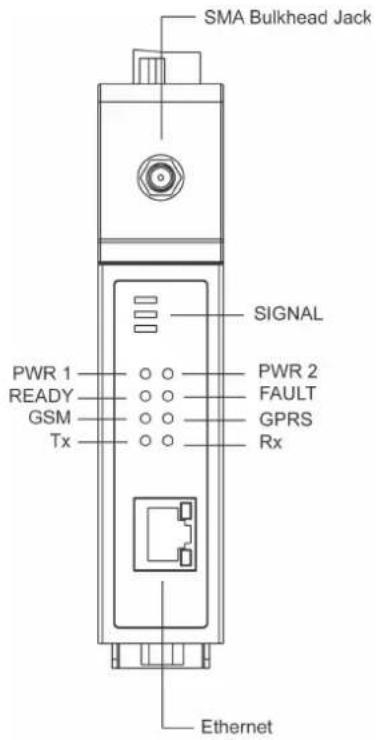
OnCell
G3110-HSPA/
G3150-HSPA
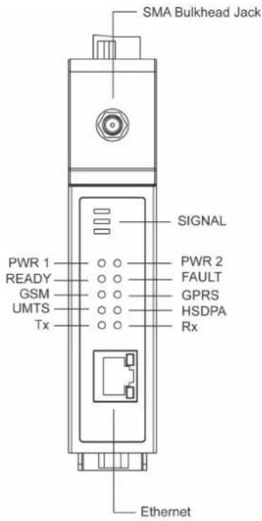
Top View
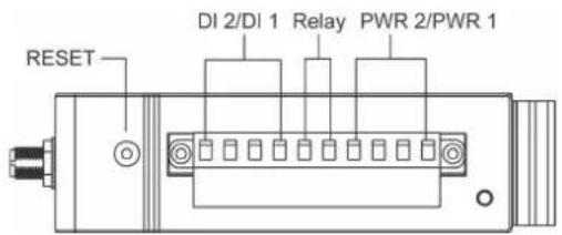
Bottom Views
For RS-232 models
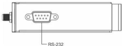
For RS-232/422/485 models
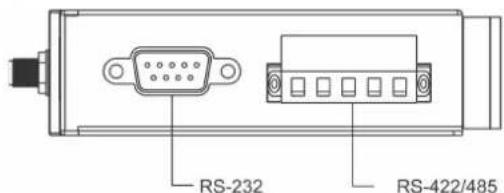
Rear View
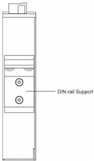
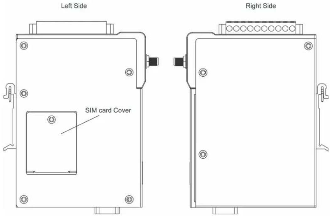
Side Views
Connecting the Hardware
This section describes how to connect the OnCell G3100 cellular IP gateway to a host PC or serial/Ethernet devices for first time testing purposes. We cover topics such as: Wiring Requirements, SIM Installation, DIN-Rail Mounting, Connecting the Power, Connecting to a Serial Device, Connecting to an Ethernet Device, Adjustable Pull High/Low Resistors for the RS-485 Port, and LED Indicators.
Wiring Requirements

ATTENTION
Safety First!
Be sure to disconnect the power cord before installing and/or wiring your device. The OnCell G3100 should be secured at one location.
Wiring Caution!
Calculate the maximum possible current in each power wire and common wire. Observe all electrical codes dictating the maximum current allowable for each wire size. If the current goes above the maximum ratings, the wiring could overheat, causing serious damage to your equipment.
Temperature Caution!
Be careful when handling the device. When plugged in, the device's internal components generate heat, and consequently the casing may feel hot to the touch.
You should also follow the guidelines below:
- Use separate paths to route wiring for power and devices. If power wiring and device wiring paths must cross, make sure the wires are perpendicular at the intersection point.
NOTE: Do not run signal or communication wiring and power wiring in the same wire conduit. To avoid interference, wires with different signal characteristics should be routed separately. - Use the type of signal transmitted through a wire to determine which wires should be kept separate. The rule of thumb is that wiring that shares similar electrical characteristics can be bundled together.
- Keep input wiring and output wiring separate.
• Where necessary, it is advisable to label the wiring to all devices in the system.
SIM Card Installation
In order to protect the SIM card, the SIM card slot is located inside the OnCell G3100's casing. You will need to unscrew and remove the outer SIM card cover before installing or removing the SIM card.
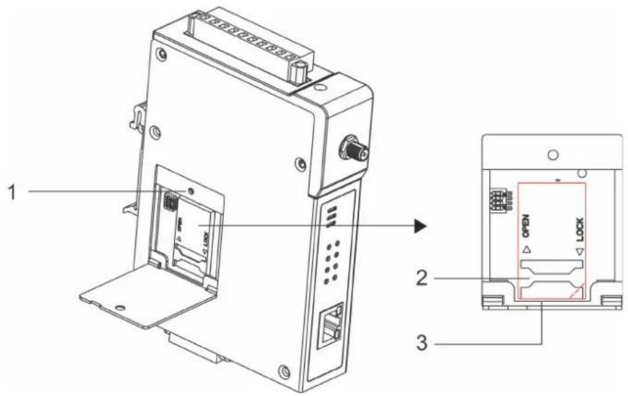
Follow these steps to remove or install the SIM card:
- Remove the screw holding the outer SIM card cover.
- Push the outer SIM card cover to the left to remove it.
- Rotate it upwards to expose the SIM card slot.
(a) Remove the SIM card from the SIM card slot, or
(b) Insert the SIM card into the SIM card slot.
- Reverse the above steps to replace the outer SIM card cover.

ATTENTION
If the IP gateway is in GSM/GPRS mode, SIGNAL LEDs will not be illuminated if the phone number or APN is incorrect. Check the GSM LED if the SIM card is installed correctly.
The GSM LEDs on the front panel provide a convenient way of checking if the SIM card is installed properly. If the antenna is installed and the network is operating normally, then at least one of the three SIGNAL LEDs should be illuminated at all times. If none of the GSM and SIGNAL LEDs are illuminated, then the SIM card may not be installed properly. This is because the PIN code is stored on the SIM card; if the PIN code cannot be accessed, then the IP gateway will not be accessible over the network.
Connecting the Power
The dual power inputs that connect to the 4-pin power terminal block (2 terminals per power input) can be used to connect the OnCell G3100 to a variety of field power sources that support 12 to 48 VDC. After connecting the power wire to the OnCell G3100's terminal block, the "PWR" LED will glow a solid green color to indicate that the system is ready.
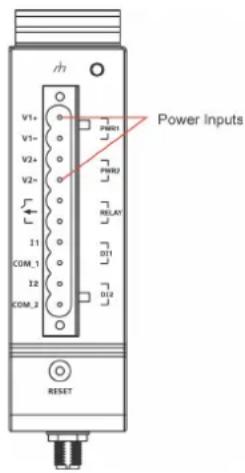
Connecting the I/O Port
Six terminals on the terminal block are reserved for the I/O ports, with 2 terminals used for each input, and 2 terminals used for the output.
Digital Input
Digital ON and OFF determine which of the 2 electrically isolated inputs are used:
• +13 to +30 V for state "1" (On)
• +3 to -30 V for state "0" (Off)
Digital Output: 1 relay output with current carrying capacity of 1A @ 24 VDC
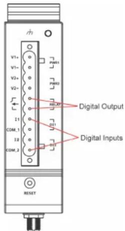
| Power Status Event Relay | ||
| Off No Open | ||
| On Yes Open | ||
| No Short | ||
Connecting to the Network
Connect one end of the Ethernet cable to the OnCell G3100's 10/100M Ethernet port and the other end of the cable to the Ethernet network.
If the cable is properly connected, the OnCell G3100 will indicate a valid connection to the Ethernet as follows:
• The Ethernet LED glows a solid green when connected to a 100 Mbps Ethernet network.
• The Ethernet LED glows a solid orange when connected to a 10 Mbps Ethernet network.
• The Ethernet LED flashes when Ethernet packets are being transmitted or received.
Connecting to a Serial Device
The OnCell G3110/G3110-HSPA supports one RS-232 port that connects through a DB9 male connector on the bottom panel.
The OnCell G3150/G3110-HSPA supports one RS-232 port that connects through a DB9 male connector on the bottom panel, and one RS-422/RS-485-4w/RS-485-2w that connects through a 5-pin terminal block on the bottom panel.
Connecting to the Ethernet Device
Connect one end of the Ethernet cable to the OnCell G3100's 10/100M Ethernet port and the other end of the cable to the Ethernet device.
If the cable is properly connected, the OnCell G3100 will indicate a valid Ethernet connection as follows:
• The Ethernet LED glows a solid green when connected to a 100 Mbps Ethernet device.
• The Ethernet LED glows a solid orange when connected to a 10 Mbps Ethernet device.
• The Ethernet LED flashes when Ethernet packets are being transmitted or received.
Adjustable Pull High/ Low Resistors for the RS-485 Port (for RS-232/ 422/ 485 models)
In some critical environments, you may need to add termination resistors to prevent the reflection of serial signals. When using termination resistors, it is important to set the pull high/low resistors correctly so that the electrical signal is not corrupted. Since a particular pull high/low resistor value cannot fit all environments, the OnCell uses DIP switches to set the pull high/low resistor values for the serial port.
- To set the termination resistor to 150 KΩ, make sure both of the assigned DIP switches are in the OFF position. This is the default setting.
- To set the termination resistor to 1K , make sure both of the assigned DIP switches are in the ON position.

ATTENTION
Do not use the 1 KΩ setting on the OnCell when using the RS-232 interface. Doing so will degrade the RS-232 signals and shorten the maximum allowed communication distance.
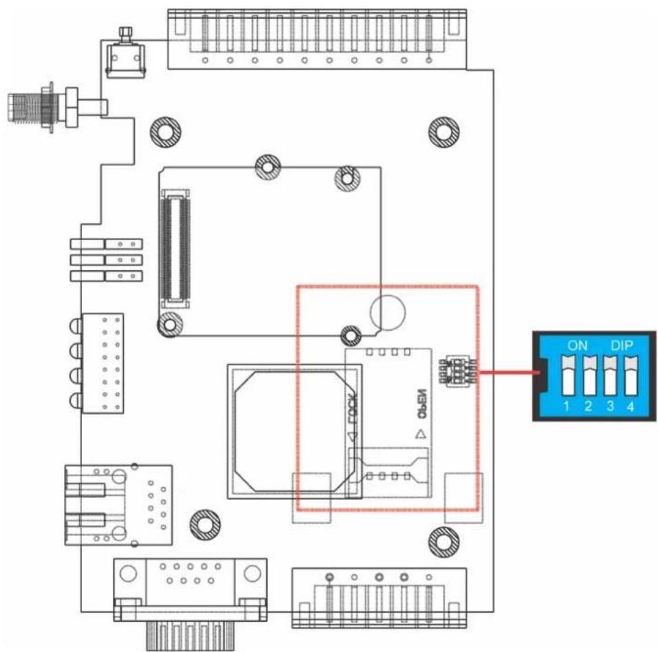
| SW 1 2 3 | |||
| Pull High Pull Low Terminator | |||
| ON | 1 KΩ | 1 KΩ | 120 KΩ |
| OFF | 150 KΩ | 150 KΩ | - |
LED Indicators
The LED indicators on the front panel of the OnCell series are described in the following table.
| LED Name | LED Color | LED Function |
| PWR | Green DC | Power is active. |
| off | Power is off, or power error condition exists. | |
| Tx | Green | The serial port is transmitting data. |
| Off | No data is being transmitted or received through the serial port. | |
| Rx | Amber | The serial port is receiving data. |
| off No data is being received through the serial port. | ||
| REG | Amber | Registered with cellular provider (only for -JPS/JPN model) |
| off | SIM slot not in used (only for -JPS/JPN model) | |
| GSM | Amber GSM is connected. | |
| off GSM is disconnected. | ||
| GRPS | Amber GPRS is connected | |
| off GPRS is disconnected. | ||
| UMTS | Amber UMTS is connected. | |
| off UMTS is disconnected. | ||
| HSPA | Amber HSPA is connected. | |
| off HSPA is disconnected. | ||
| Ready | Green | Steady on: Software Ready.Blinking slowly (1 sec): The OnCell has been located by the OnCell Search Utility. |
| off | Power is off, or is booting up. | |
| Fault | Red | Steady on: Booting up, or IP fault.Blinking slowly (1 sec): Cannot get an IP address from the DHCP server |
| off | Power is off, or there is no error condition. | |
| Signal (3 LEDs) | Green | Signal Level(at least 2 LEDs must illuminated for data transmission) |

ATTENTION
GSM LED:
OFF: Cannot register with cellular providers using GSM mode, due to the wrong PIN code, or no cellular provider available. Signal LEDs will also be off.
ON: Registered with cellular provider. Signal LEDs will be on.
GPRS LED:
OFF: Ca nnot register with cellular providers using GPRS mode, due to wrong PIN code (GSM/signal LEDs off), no cellular provider available (GSM/signal LEDs off), wrong APN (GSM on/signal LEDs off), or wrong username/password (GSM on/signal LEDs off).
ON: Registered with cellular provider using GPRS mode. GSM/Signal LEDs will be on.
UMTS/ HSPA LED:
OFF: Cannot register with cellular providers using UMTS/HSPA mode due to the wrong PIN code (UMTS or HSPA/signal LEDs off), no cellular provider available (UMTS or HSPA/signal LEDs off), wrong APN (UMTS or HSPA on/signal LEDs off), or wrong username/password (UMTS or HSPA on/signal LEDs off).
ON: Registered with cellular provider using UMTS/HSPA mode. UMTS or HSPA/Signal LEDs will be on.
Reset Button
Press the Rest button continuously for 5 sec to load factory defaults: Use a pointed object, such as a straightened paper clip or toothpick, to press the reset button. This will cause the Ready LED to blink on and off. The factory defaults will be loaded once the Ready LED stops blinking (default IP: 192.168.127.254).
When setting up the OnCell G3100 for the first time, the first thing you should do is configure its IP address. This chapter introduces the different methods that can be used. Please refer to Chapter 14: System Management Settings, for more details about network settings.
The following topics are covered in this chapter:
☐ Static and Dynamic IP Addresses
□ Factory Default IP Address
□ Configuration Options
OnCell Search Utility
Web Console
ARP
Telnet Console
Serial Console
Static and Dynamic IP Addresses
Determine whether your OnCell G3100 needs to use a static IP address or dynamic IP address (either DHCP or BOOTP application).
- If your OnCell G3100 is used in a static IP environment, you must assign a specific IP address using one of the tools described in this chapter.
- If your OnCell G3100 is used in a dynamic IP environment, the IP address will be assigned automatically from over the network. In this case, set the IP configuration mode to DHCP or BOOTP.

ATTENTION
Consult your network administrator on how to reserve a fixed IP address for your OnCell G3100 in the MAC-IP mapping table when using a DHCP Server or BOOTP Server. For most applications, you should assign a fixed IP address to your OnCell G3100.
Factory Default IP Address
The OnCell G3100 is configured with the following default private IP address:
192.168.127.254
Note that IP addresses that begin with "192.168" are referred to as private IP addresses. Devices configured with a private IP address are not directly accessible from a public network. For example, you would not be able to ping a device with a private IP address from an outside Internet connection. If your application requires sending data over a public network, such as the Internet, your OnCell G3100 will need a valid public IP address, which can be leased from a local ISP.
Configuration Options
OnCell Search Utility
You may configure your OnCell G3100 with the bundled OnCell Search Utility for Windows. Please refer to Chapter 15, Software Installation/Configuration, for details on how to install and use OnCell Search Utility.
Web Console
You may configure your OnCell G3100 using a standard web browser. Please refer to Chapter 6, Using the Web Console, for details on how to access and use the OnCell G3100 web console.
ARP
You may use the ARP (Address Resolution Protocol) command to set up an IP address for your OnCell G3100. The ARP command tells your computer to associate the OnCell G3100's MAC address with an IP address. Afterwards, use Telnet to access the OnCell G3100 and its IP address will be reconfigured.

ATTENTION
In order to use the ARP setup method, both your computer and the OnCell G3100 must be connected to the same LAN. You may use an Ethernet cable to connect the OnCell G3100 directly to your computer's Ethernet card. Before executing the ARP command, your OnCell G3100 must be configured with the factory default IP address (192.168.127.254) and your computer and the OnCell G3100 must be on the same subnet. In addition, note that ARP command must be issued within 3 minutes after the OnCell is turned. After 3 minutes have elapsed, the OnCell will no longer accept ARP commands.
To use ARP to configure the IP address, complete the following:
- Obtain a valid IP address for your OnCell G3100 from your network administrator.
- Obtain your OnCell G3100's MAC address from the label on the bottom panel.
- Execute the arp -s command from your computer's MS-DOS prompt as follows:
arp -s < IP address> < MAC address>
For example,
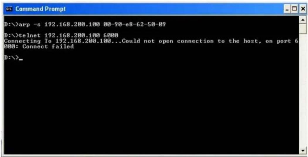
C:> arp -s 192.168.200.100 00-90-E8-04-00-11
- Next, execute a special Telnet command by entering the following exactly:
telnet 192.168.200.100 6000
When you enter this command, a Connect failed message will appear, as shown below.
- After the OnCell G3100 reboots, its IP address will be assigned to the new address and you can reconnect using Telnet to verify that the update was successful.
Telnet Console
Depending on how your computer and network are configured, you may find it convenient to use network access to set up your OnCell G3100's IP address. This can be done using Telnet.

ATTENTION
Figures in this section were taken from the OnCell G3100's Telnet console.
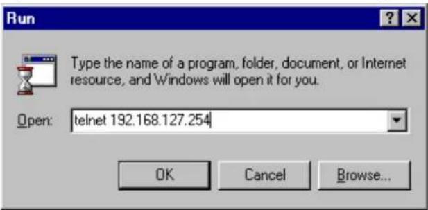
- From the Windows desktop, select Start → Run, and then type the following content in the Run window: telnet 192.168.127.254
If your IP address is different from the default setting, use your IP address instead. Click OK.
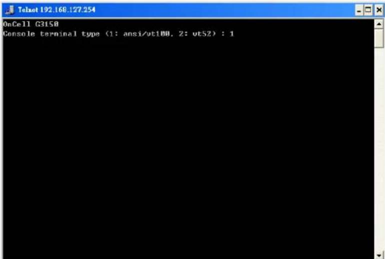
- The console terminal type selection is displayed as shown. Enter 1 for ansi/ vt100, and then press ENTER to continue.
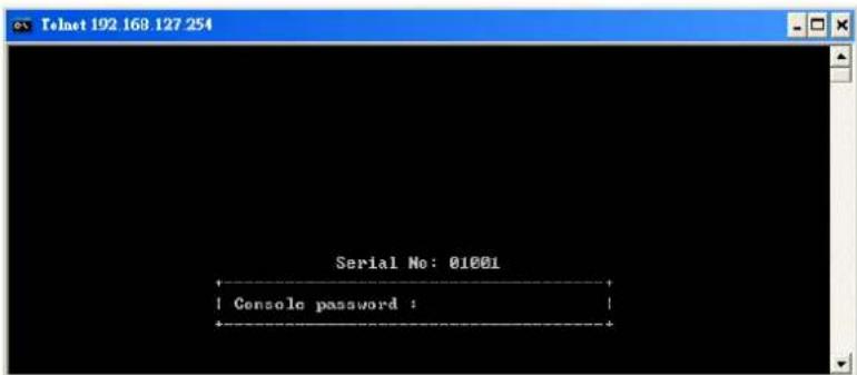
- The following page will only appear if the OnCell G3100 is password protected. Enter the console password if you are prompted to do so, and then press ENTER.
- Press N or use the arrow keys to select Network, and then press ENTER.
![Telnet 192.168.127.254 OnCell G3150 OnCell G3150_2 1.0 Overview Basic [Network] Port System Monitor save Restart Exit Examine/modify the ethernet LAN port settings. Enter: select ESC: previous menu](/content/2026/06/1160625/images/0176296e2ba6d2c4b81743ba6ca2f9c4a7d5806bff0d2641da7e87c2d48e4ea1.jpg)
- Press B or use the arrow keys to select Basic, and then press ENTER.
![Telnet 192.168.40.42 OnCell G3150 OnCell G3150_2 1.0 [Basic] Advanced auto_ip_report Com/Cpro Quit Examine/modify basic network settings. Enter: select ESC: previous menu](/content/2026/06/1160625/images/ce1e4c66082d22de13c01bb9195a61d77b41baf52d6d7b80e13cb901246c3bb4.jpg)
- Use the arrow keys to move the cursor to IP address. Use the DELETE, BACKSPACE, or SPACE keys to erase the current IP address, and then type in the new IP address and press ENTER. Note that if you are using a dynamic IP configuration (BOOTP, DHCP, etc.), you will need to go to the IP configuration field and press ENTER to select the appropriate configuration.
![[Basic] Advanced auto_Ip_report Gsm/Gps Quit Examine/modify basic network settings ESC: back to menu Enter: select IP configuration [Static ] IP address [192.168.127.254] Netmask [255.255.255.0] Gateway [ ] DNS server 1 [ ] DNS server 2 [ ] WINS function [Enable ] WINS server [ ] LAN speed [Auto ]](/content/2026/06/1160625/images/0c1ff04af6c2cc4b898b2b5062e76aeabe7730f2af8c3bb01b5ef9974de8340f.jpg)
- Press ESC twice to return to the previous page. Press Y to confirm.
![[Basic] Advanced auto_Ip_report Gen/Gpro Quit Examine/modify basic network settings Enter: select ESC: previous menu Warning !!! You have modified the configuration without saving. Would you save it now ? 'Y: yes 'N': no_](/content/2026/06/1160625/images/b213499a57841ef612847f7ad666c6bef30d46e8c0cf59406ddf7b95a48c04aa.jpg)
-
Press ESC to return to the previous page.
-
Press A or use the arrow keys to select Save and then press ENTER. Press ENTER again to confirm the save command.
![Telnet 192.168.127 254 OnCell G3150 OnCell G3150_2 1.0 Overview Basic Network Port System Monitor [sAve] Restart Exit Save current configuration to flash ROM ESC: back to menu Enter: select Enter to update, other key to cancel](/content/2026/06/1160625/images/fda4b701e79d14e20bf40fc1bd79d7bba0ffd030e78eac3557109b47cdb8152e.jpg)
- Press R or use the arrow keys to select Restart and then press ENTER.
![OnCell G3150 OnCell G3150_2 1.0 Overview Basic Network Fort System Monitor SAVE [Restart] Exit Restart the whole system or selected serial ports. Enter: select ESC: previous menu](/content/2026/06/1160625/images/fe9348ad6a5c60e6a87d1986a6e501715cbebb7995e2835d321241f56a5cac13.jpg)
- Press S or use the arrow keys to select System and then press ENTER to restart the OnCell G3100.
![[System] Port Quit Restart the server ESC: back to menu Enter: select Warning !!! ! Restart system will disconnect all ports and clear all status value ! Enter: continue ESC: cancel_](/content/2026/06/1160625/images/43ed410bcabde948ad988e5663a0569a74992ee35e785b689fa6225e77b1b86d.jpg)
Serial Console
The OnCell G3100 supports configuration through the serial console, which is the same as the Telnet console but accessed through the RS-232 console port rather than over the network. Once you have entered the serial console, the configuration options and instructions are the same as if you were using the Telnet console.
The following instructions and screenshots show how to enter the serial console using PComm Terminal Emulator, which is available free of charge as part of the PComm Lite suite. You may use a different terminal emulator utility, although your actual screens and procedures may vary slightly from the following instructions.
- Turn off the power to the OnCell G3100. Use a serial cable to connect the OnCell G3100's serial console port to your computer's RS-232 serial port.
- From the Windows desktop select Start → All Programs → PComm Lite → Terminal Emulator.
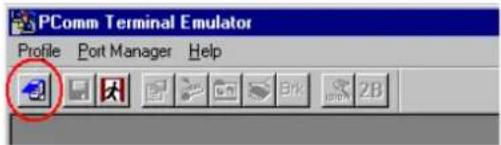
- The PComm Terminal Emulator window should appear. From the Port Manager menu, select Open, or simply click the Open icon as shown below:
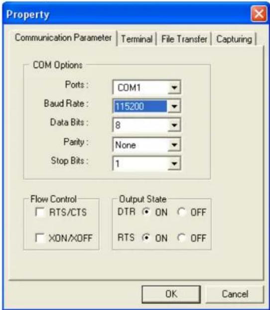
- The Property window opens automatically. Select the Communication Parameter tab, and then select the appropriate COM port for the connection (COM4 in this example). Configure the parameters for 115200, 8, N, 1 (115200 for Baudrate, 8 for Data Bits, None for Parity, and 1 for Stop Bits).
-
From the Property window's Terminal page, select ANSI or VT100 for Terminal Type and then click OK.
-
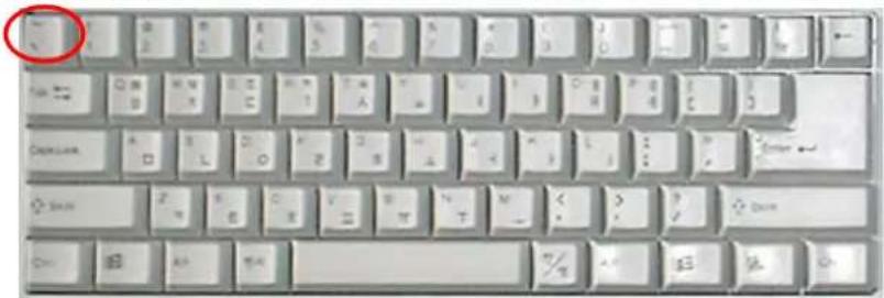
If you are using the OnCell G3100, you may power it up at this point and hold down the "grave accent key" ( ) while powering it up, as shown below. Note that the grave accent key (sometimes called "backwards apostrophe") is NOT the apostrophe key—it is the key usually found next to the number 1 key.
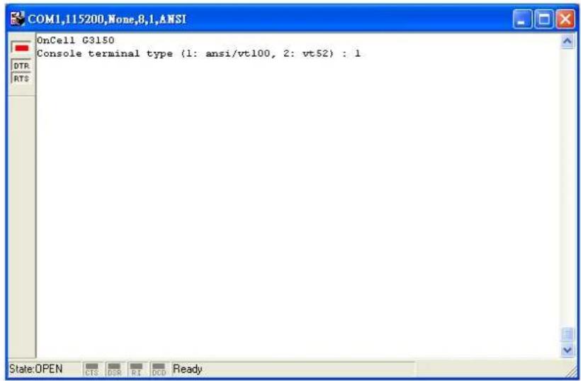
- If the OnCell G3100 has been set up for password protection, you will be prompted to enter the password. After you enter the password, or if password protection was not enabled, you will be prompted to select the terminal mode. Press 1 for ansi/ vt100 and then press ENTER.
- The main menu should appear. Once you are in the console, you may configure the IP address through the Network menu item, just as with the Telnet console. Please refer to steps 4 to 11 in the Telnet Console section to complete the initial IP configuration.
![COM1,115200,None,8,1,ANSI OnCell G3150 OnCell G3150_2 1.0 Overview Basic [Network] Port System Monitor sAve Restart Exit Examine/modify the ethernet LAN port settings Enter: select ESC: previous menu](/content/2026/06/1160625/images/a4d40ede0d9ca65153795944e8a9719d6d656ed7e4d9b88cf3adcb2b1ad21587.jpg)
In this chapter, we describe the various operation modes of the OnCell G3100. The OnCell G3100 modes are grouped by type of application, such as Device Control. The options include an operation mode that relies on a driver installed on the host computer, and operation modes that rely on TCP/IP socket programming concepts. After selecting the proper operation mode, please refer to Chapter 6: Using the Web Console, for detailed information on configuration parameters.
The following topics are covered in this chapter:
Overview
□ Device Control Applications
Real COM and Secure Real COM Modes
Types of Real COM Connection
➢ Reverse Real COM and Secure Reverse Real COM Modes
Types of Reverse Real COM Connection
RFC 2217 Mode
□ Socket Applications
TCP Server and Secure TCP Server Modes
Types of TCP Server Connection
TCP Client and Secure TCP Client Modes
Types of TCP Client Connection
▶ UDP Mode
Types of UDP Connection
☐ Ethernet Modem Mode
□ SMS Tunnel Mode
□ Disabled Mode
Overview
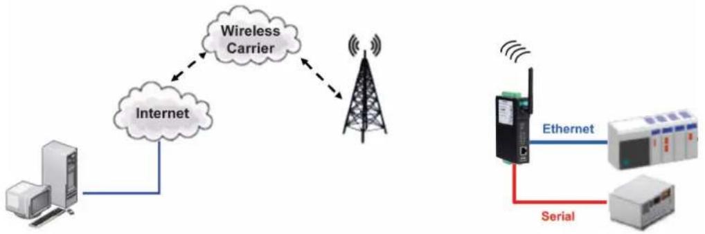
The OnCell G3100 IP gateway can cellular network-enable a serial device. OnCell G3100 IP gateway device is assigned an IP address by your service provider (your "cellular ISP"). In addition, the OnCell G3100 IP gateway can cellular network-enable Ethernet devices on the local Ethernet – see chapter 5 for details.
flowchart
graph TD
    A["Server"] --> B["Internet"]
    B --> C["Wireless Carrier"]
    C --> D["Tower Station"]
    D --> E["Ethernet"]
    E --> F["Serial"]
    F --> G["Server"]
    style A fill:#f9f,stroke:#333
    style B fill:#ccf,stroke:#333
    style C fill:#cfc,stroke:#333
    style D fill:#fcc,stroke:#333
    style E fill:#cff,stroke:#333
    style F fill:#ffc,stroke:#333
    style G fill:#fcc,stroke:#333
For Cellular-Enabling Serial Devices, The OnCell G3100 cellular IP gateway enables traditional serial (RS-232/422/485) devices for transmitting data over the cellular network. The IP gateway is a tiny computer equipped with a CPU and TCP/IP protocols that can bi-directionally translate data between the serial and IP formats. With the OnCell G3100, your computer will be able to access, manage, and configure remote facilities and equipment over the cellular network from anywhere in the world.
Traditional SCADA and data collection systems rely on serial ports to collect data from various kinds of instruments. Since the OnCell G3100 cellular IP gateway network-enables instruments equipped with an RS-232, RS-422, or RS-485 communication port, your SCADA and data collection system will be able to access all instruments connected to a standard TCP/IP network, regardless of whether the devices are used locally or at a remote site.
The OnCell G3100 is an external IP-based network device that allows you to expand a serial port for a host computer on demand. As long as your host computer supports the TCP/IP protocol, you will not be limited by the host computer's bus limitation (such as ISA or PCI), nor will you be limited if you do not have drivers for various operating systems.
In addition to providing socket access, the OnCell G3100 also comes with a Real COM/TTY driver and a Reverse Real COM/TTY driver that transmits all serial signals intact. This enables you to preserve your existing COM/TTY-based software without needing to invest in additional software.
Three different socket modes are available: TCP Server, TCP Client, and UDP. The main difference between the TCP and UDP protocols is that TCP guarantees delivery of data by requiring the recipient to send an acknowledgement to the sender. UDP does not require this type of verification, making it possible to offer faster delivery. UDP also allows you to unicast data to one IP, or multicast the data to a group of IP addresses.
The OnCell G3100 supports standard SSL secure data access for Real COM/TTY modes, Reverse Real COM/TTY modes, TCP server mode, and TCP Client mode to protect data transmitted over the cellular network.
Device Control Applications
The OnCell G3100 offers the following modes for device control applications: Real COM/Secure Real COM, Reverse Real COM/Secure Reverse Real COM, and RFC2217 modes.
Real COM and Secure Real COM Modes
The OnCell G3100 comes bundled with Moxa drivers for Windows 98/ME/NT/2000/XP/2003/2008/Vista systems and TTY drivers for Linux and Unix systems. Real COM mode includes optional data encryption using SSL. (For Windows systems, this option is only supported for Windows 2000, XP x86/x64, 2003 x86/x64, Vista x86/x64, and 2008 x86/x64.)
In Real COM mode, the bundled drivers are able to establish a transparent connection between a host and a serial device by mapping the serial port on the OnCell G3100 to a local COM/TTY port on the host computer. Real COM mode supports up to 2 simultaneous connections that enable 2 hosts to simultaneously collect data from the same serial device.
One of the major conveniences of using Real COM mode is that it allows you to use software that was written for pure serial communication applications. The OnCell COM driver intercepts data sent to the host's COM port, packs it into a TCP/IP packet, and then redirects it through the host's Ethernet card to the Internet. At the other end of the connection, the OnCell G3100 accepts the IP frame from the cellular network, unpacks the TCP/IP packet, and then transparently sends the data through the serial port to the attached serial device.
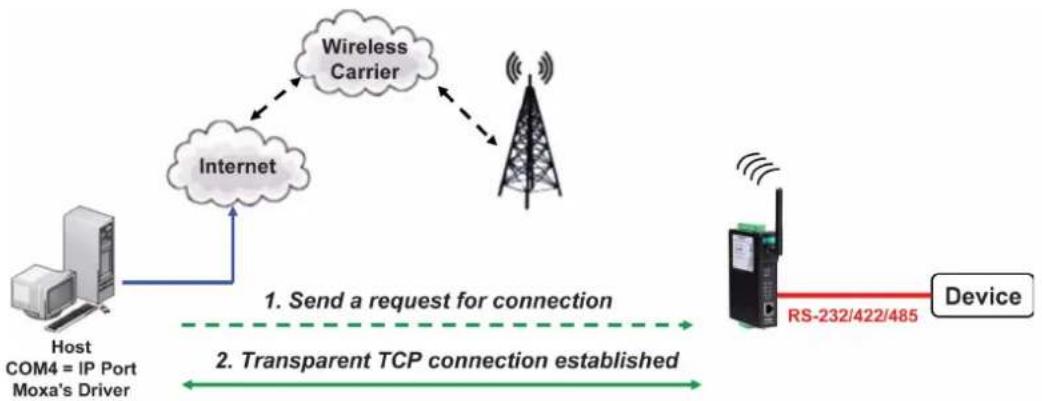
flowchart
graph TD
    A["Host COM4 = IP Port Moxa's Driver"] --> B["Internet"]
    B --> C["Wireless Carrier"]
    C --> D["Device"]
    D --> E["RS-232/422/485"]
    style A fill:#f9f,stroke:#333
    style B fill:#ccf,stroke:#333
    style C fill:#cfc,stroke:#333
    style D fill:#fcc,stroke:#333
    style E fill:#cff,stroke:#333
Types of Real COM Connection
This section illustrates the types of RealCOM connections you can use, depending on the service you obtain from your local cellular service provider.
Fixed Public IP for OnCell
If your cellular service provider offers a fixed public IP address after you connect to the cellular network, you can access the OnCell G3100 via a host PC using either a private IP or public IP.
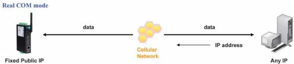
flowchart
graph LR
    A["Real COM mode"] -->|data| B["Cellular Network"]
    B -->|data| C["Any IP"]
    B -->|IP address| C
    style A fill:#f9f,stroke:#333
    style B fill:#ccf,stroke:#333
    style C fill:#cfc,stroke:#333
Utilize Auto IP report
If your cellular service provider offers a dynamic public IP address after you connect to the cellular network, you can access the OnCell G3100 via a host PC using a fixed public IP. Since the IP address of the OnCell G3100 is changed each time it is connected to the cellular network, the host IP can be notified of the change by an Auto IP Report message sent from the OnCell G3100. Please refer to Appendix E to see the format of the Auto IP Report Protocol.
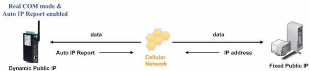
flowchart
graph LR
    A["Dynamic Public IP"] -->|data| B["Cellular Network"]
    B -->|data| C["Fixed Public IP"]
    D["Real COM mode & Auto IP Report enabled"] -->|Auto IP Report| B
    B -->|IP address| C
Domain name with DDNS
If your cellular service provider offers a public IP address after you connect to the cellular network, you can also access the OnCell G3100 using the domain name. To do this, you will need to register with a DDNS service provider and then enable the DDNS function in the OnCell G3100. Please refer to Appendix C for more information.
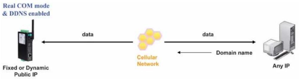
flowchart
graph LR
    A["Fixed or Dynamic Public IP"] <-->|data| B["Cellular Network"]
    B <-->|data| C["Any IP"]
    B -->|Domain name| C
    style A fill:#f9f,stroke:#333
    style B fill:#ccf,stroke:#333
    style C fill:#cfc,stroke:#333
Reverse Real COM and Secure Reverse Real COM Modes
The OnCell G3100 comes bundled with Moxa drivers for Windows 98/ME/NT/2000/XP/2003/2008/Vista systems and TTY drivers for Linux and Unix systems. Reverse Real COM mode includes optional data encryption using SSL. (For Windows systems, this option is only supported for Windows 2000, XP x86/x64, 2003 x86/x64, Vista x86/x64, and 2008 x86/x64.)
Reverse Real COM mode uses a mechanism similar to port mapping to enable your remote device that is using a private IP address to remain accessible to external hosts. When this mode is enabled, the Moxa driver that comes with the device establishes a transparent connection from the device to the remote host by mapping the device's serial port to a local COM port on the remote host. Reverse Real COM mode supports up to 2 simultaneous connections that enable serial devices to send data to 2 hosts simultaneously.
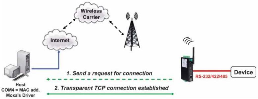
flowchart
graph TD
    A["Host COM4 = MAC add. Moxa's Driver"] --> B["Internet"]
    B --> C["Wireless Carrier"]
    C --> D["Device"]
    D --> E["RS-232/422/485"]
    style A fill:#f9f,stroke:#333
    style B fill:#ccf,stroke:#333
    style C fill:#cfc,stroke:#333
    style D fill:#fcc,stroke:#333
    style E fill:#cff,stroke:#333
Types of Reverse Real COM Connection
Reverse RealCOM to PC's IP address
Most cellular service providers only provide customers with a dynamic private IP address, which means that the OnCell G3100 will only obtain an IP address once it is connected to the cellular network. Reverse RealCOM is a great feature that allows a PC host to access an OnCell G3100 configured with private IP address.
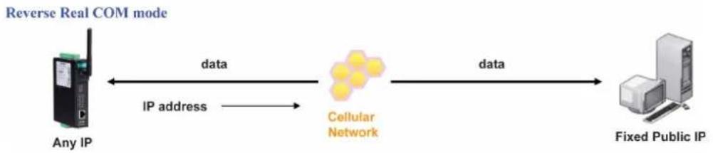
flowchart
graph LR
    A["Any IP"] -->|IP address| B["Cellular Network"]
    B -->|data| C["Fixed Public IP"]
    style A fill:#f9f,stroke:#333
    style C fill:#ccf,stroke:#333
Reverse RealCOM to PC's domain name
With Reverse RealCOM mode, you can connect to a PC host using the PC's IP address. You can also connect to your PC host with the PC's domain name, if you have one. Please refer to Appendix C for more information.
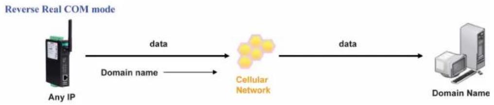
flowchart
graph LR
    A["Any IP"] -->|data| B["Cellular Network"]
    B -->|data| C["Domain Name"]
    style A fill:#f9f,stroke:#333
    style B fill:#ccf,stroke:#333
    style C fill:#cfc,stroke:#333
RFC 2217 Mode
RFC-2217 mode is similar to Real COM mode in that a driver is used to establish a transparent connection between a host computer and a serial device by mapping the serial port on the OnCell G3100 to a local COM port on the host computer. RFC2217 defines general COM port control options based on the Telnet protocol. Third party drivers supporting RFC-2217 are widely available on the Internet and can be used to implement virtual COM mapping to your OnCell G3100's serial port. Please refer to Appendix B for more information.
Socket Applications
The OnCell G3100 offers the following modes for socket applications: TCP Server and Secure TCP Server, TCP Client and Secure TCP Client, and UDP.
TCP Server and Secure TCP Server Modes
In TCP Server mode, the serial port on the OnCell G3100 is assigned a port number. The host computer initiates contact with the OnCell G3100, establishes the connection, and receives data from the serial device. This operation mode also supports up to 2 simultaneous connections, enabling multiple hosts to collect data from the same serial device at the same time.
As illustrated in the figure, data transmission proceeds as follows: The host requests a connection from the OnCell G3100, which is configured for TCP Server mode. Once the connection is established, data can be transmitted in both directions between the host and the OnCell G3100.
TCP Server mode includes optional data encryption using SSL
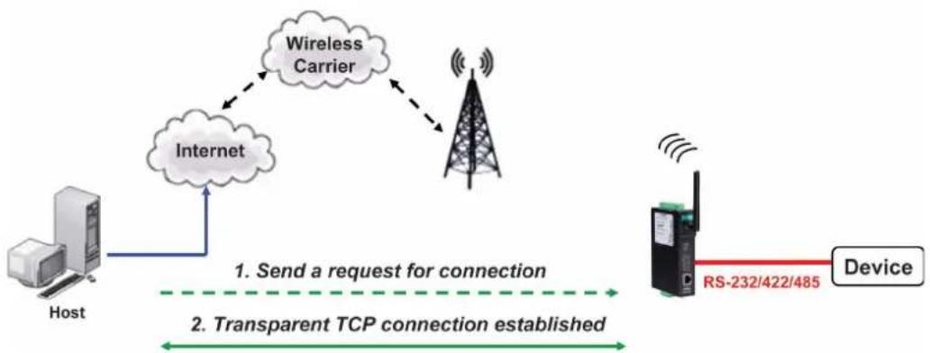
flowchart
graph TD
    A["Host"] --> B["Internet"]
    B --> C["Wireless Carrier"]
    C --> D["Device"]
    D --> E["RS-232/422/485"]
    style A fill:#f9f,stroke:#333
    style B fill:#ccf,stroke:#333
    style C fill:#cfc,stroke:#333
    style D fill:#fcc,stroke:#333
    style E fill:#cff,stroke:#333
Types of TCP Server Connection
Fixed Public IP for the OnCell
If your cellular service provider offers a fixed public IP address after you connect to the cellular network, you can access the OnCell G3100 from a host PC using either a private IP or public IP.
TCP Server mode

flowchart
graph LR
    A["Fixed Public IP"] <-->|data| B["Cellular Network"]
    B <-->|data| C["Any IP"]
    B -->|IP address| C
Using Auto IP report
If your cellular service provider offers a dynamic public IP address after you connect to the cellular network, you can access the OnCell G3100 from a host PC using a fixed public IP. Since the IP address of the OnCell G3100 is changed every time it is connected to the cellular network, the host IP can be aware of the change by the Auto IP Report message sent from the OnCell G3100. Please refer to Appendix E for the format of the Auto IP Report Protocol.
TCP Server mode & Auto IP Report enabled

flowchart
graph LR
    A["Dynamic Public IP"] <-->|data| B["Cellular Network"]
    B <-->|data| C["Fixed Public IP"]
    A <-->|Auto IP Report| B
    B <-->|IP address| C
Domain name with DDNS
If your cellular service provider offers a public IP address after you connect to the cellular network, you can also use the domain name to access the OnCell G3100. You would need to register with a DDNS service provider and then enable the DDNS function in the OnCell G3100. Please refer to Appendix C for more information.
TCP Server mode & DDNS enabled
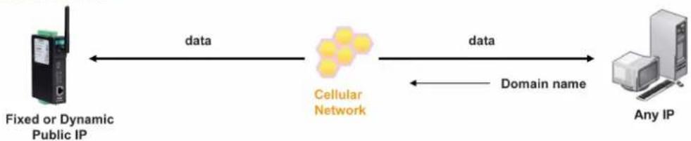
flowchart
graph LR
    A["Fixed or Dynamic Public IP"] <-->|data| B["Cellular Network"]
    B <-->|data| C["Any IP"]
    B -->|Domain name| C
Connecting TCP client and TCP server within the same cellular service provider
In order to connect properly, the IP addresses of the two OnCell devices must belong to the same subnetwork. To ensure that this is the case, use the same cellular service provider to connect the devices to the network. In addition, you will need to request that the cellular service provider provide you with two private IP addresses (e.g., 192.168.1.1 and 192.168.1.2).
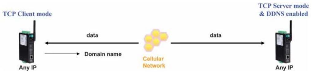
flowchart
graph LR
    A["TCP Client mode"] -->|data| B["Cellular Network"]
    B -->|data| C["Any IP"]
    A <-->|Domain name| B
    D["TCP Server mode & DDNS enabled"] --> C
TCP Client and Secure TCP Client Modes
In TCP Client mode, the OnCell G3100 can actively establish a TCP connection to a pre-defined host computer when serial data arrives. After the data has been transferred, the OnCell G3100 can automatically disconnect from the host computer by using the Inactivity time settings.
As illustrated in the figure below, data transmission proceeds as follows:
- The OnCell G3100, configured for TCP Client mode, requests a connection to the host.
- Once the connection is established, data can be transmitted in both directions between the host and the OnCell G3100.
TCP Client mode includes optional data encryption using SSL.
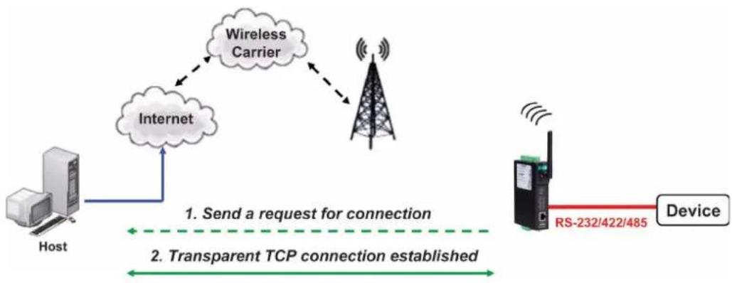
flowchart
graph TD
    A["Host"] --> B["Internet"]
    B --> C["Wireless Carrier"]
    C --> D["Device"]
    D --> E["RS-232/422/485"]
    style A fill:#f9f,stroke:#333
    style B fill:#ccf,stroke:#333
    style C fill:#cfc,stroke:#333
    style D fill:#fcc,stroke:#333
    style E fill:#cff,stroke:#333
Types of TCP Client Connection
TCP Client to PC's IP address
The OnCell G3100 will only be able to connect to a host PC if the PC is using a public IP address.
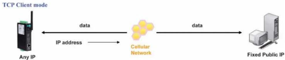
flowchart
graph LR
    A["Any IP"] -->|IP address| B["Cellular Network"]
    B -->|data| C["Fixed Public IP"]
    style A fill:#f9f,stroke:#333
    style B fill:#ccf,stroke:#333
    style C fill:#dfd,stroke:#333
TCP Client to PC's domain name
To connect to a host PC, the host PC must be configured with public IP address. If it is using a dynamic public IP, then the OnCell G3100 can connect to it using the host's domain name. Please refer to Appendix C for more information.
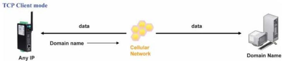
flowchart
graph LR
    A["Any IP"] -->|data| B["Cellular Network"]
    B -->|data| C["Domain Name"]
    style A fill:#99ccff,stroke:#333
    style B fill:#ffcccc,stroke:#333
    style C fill:#ffffff,stroke:#333
Connecting TCP client and TCP server within the same cellular service provider
In order to connect properly, the IP addresses of the two OnCell devices must belong to the same subnetwork. To ensure that this is the case, use the same cellular service provider to connect the devices to the network. In addition, you will need to request that the cellular service provider provide you with two private IP addresses (e.g., 192.168.1.1 and 192.168.1.2).
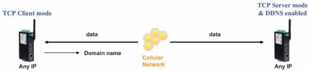
flowchart
graph LR
    A["TCP Client mode"] -->|data| B["Cellular Network"]
    B -->|data| C["TCP Server mode & DDNS enabled"]
    A -->|Domain name| B
    B -->|Domain name| C
UDP Mode
Compared to TCP communication, UDP is faster and more efficient. In UDP mode, you can unicast to one host or multicast to multiple hosts and the serial device can receive data from one or multiple host computers. These traits make UDP mode especially well suited for message display applications.
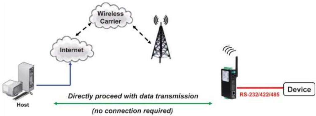
flowchart
graph LR
    A["Host"] --> B["Internet"]
    B --> C["Wireless Carrier"]
    C --> D["Device"]
    D --> E["RS-232/422/485"]
    style A fill:#f9f,stroke:#333
    style B fill:#ccf,stroke:#333
    style C fill:#cfc,stroke:#333
    style D fill:#fcc,stroke:#333
    style E fill:#cff,stroke:#333
Types of UDP Connection
Fixed Public IPs for both OnCell and Host PC
If your cellular service provider offers a fixed public IP address after you connect to the cellular network, you can access the OnCell G3100 from a host PC that has a fixed public IP.
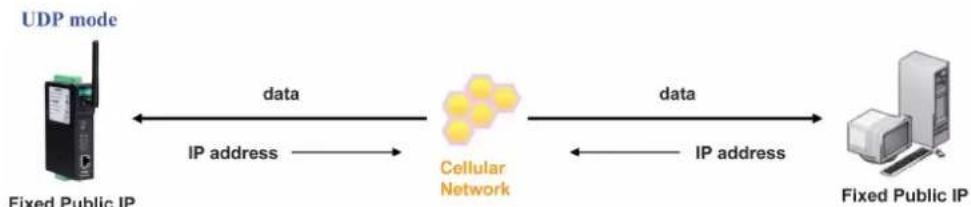
flowchart
graph LR
    A["Fixed Public IP"] -->|data| B["Cellular Network"]
    B -->|data| C["Fixed Public IP"]
    A <-->|IP address| B
    C <-->|IP address| B
Domain name with DDNS
If your cellular service provider assigns a public IP address after you connect to the cellular network, you can also access the OnCell G3100 using the domain name. If your service provider assigns a public IP address (either fixed or dynamic) to your cellular device and your control center is the side that initiates the connection, you can enable the DDNS function and UDP mode to allow other devices on the Internet to connect to your device using its domain name. This will ensure that your device will remain reachable even when its public IP address is updated. Note that you will need to register your device with a DDNS server. Please refer to Appendix C for more information.
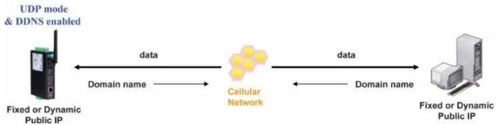
flowchart
graph LR
    A["Fixed or Dynamic Public IP"] -->|data| B["Cellular Network"]
    B -->|data| C["Fixed or Dynamic Public IP"]
    A <-->|Domain name| B
    C <-->|Domain name| B
    D["UDP mode & DDNS enabled"] --> A
    D --> C
Ethernet Modem Mode
Ethernet Modem mode is designed for use with legacy operating systems, such as MS-DOS, that do not support TCP/IP networks. By connecting a properly configured OnCell G3100 serial port to the MS-DOS computer's serial port, it is possible to use legacy software to transmit data over the cellular network, even if the software was originally designed to transmit data through a modem. In this case, the AT commands are converted into IP format.
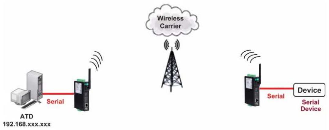
flowchart
graph TD
    A["ATD 192.168.xxx.xxx"] -->|Serial| B["Antenna"]
    B -->|Signal| C["Wireless Carrier"]
    C --> D["Device"]
    D -->|Serial| E["Antenna"]
    E -->|Signal| F["Device"]
SMS Tunnel Mode
A major benefit of GSM technology is that it supports short messages (SMS) for easy communication over the mobile network. Moxa's proprietary SMS Tunnel Mode allows you to expand your applications and reduce cost. For example, SMS Tunnel Mode can be used to update the message on a highway display panel, place refill orders for vending machines, handle maintenance for remote rental equipment, or even help create an SMS alarm by directly transforming text, binary, or unicode data from a legacy device to short messages. SMS Tunnel Mode is particularly suitable for devices that communicate infrequently, or lack access to the local network. SMS Tunnel Mode converts ASCII, binary code, and UCS2 data to short messages transparently (both back and forth). In addition, the caller ID (phone number) identification can be used to block messages sent from uncertified users, broadcast messages, and unwanted SMS advertisements.
Moxa's proprietary SMS Tunnel Mode has the following features:
- Transparently converts serial data to short message, and vise versa.
- Text, binary, and Unicode formats are supported.
- Verification of Incoming Caller ID calls is implemented to block uncertified users.
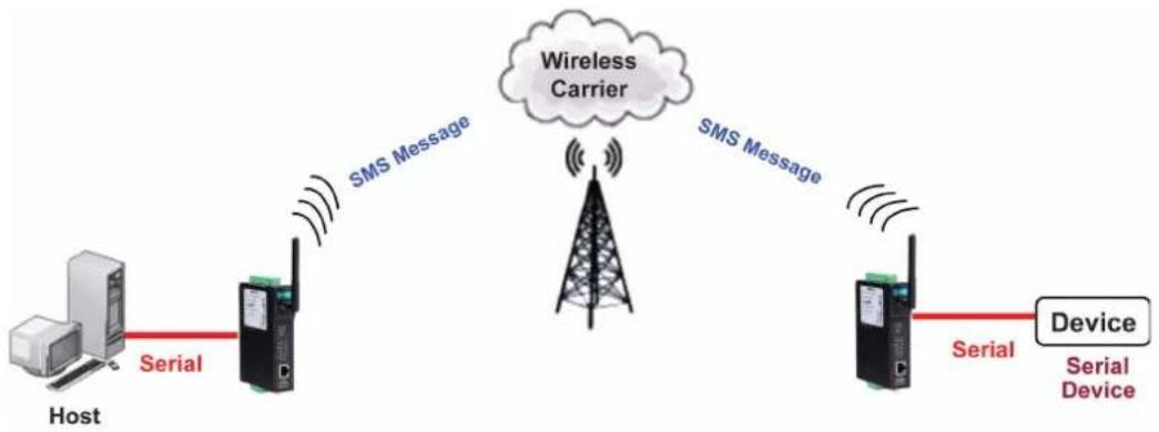
flowchart
graph LR
    Host["Host"] -->|Serial| Carrier1["Carrier"]
    Carrier1 -->|SMS Message| WirelessCarrier["Wireless Carrier"]
    WirelessCarrier -->|SMS Message| Device["Device"]
    Device -->|Serial| SerialDevice["Serial Device"]
Disabled Mode
You can disable any port on the OnCell G3100 by setting the operation mode to Disabled.
Introducing OnCell Central Manager and Ethernet Operation Modes
In this chapter, we introduce OnCell Central Management Software for host and device sites in the private IP domain. We also describe the Ethernet operation modes of the OnCell G3100. The OnCell G3100 not only connects serial devices to cellular networks, but Ethernet devices as well. After selecting the proper operation mode, please refer to Chapters 9, 10, 11, and 13 for detailed information on configuration.
The following topics are covered in this chapter:
□ OnCell Central Management Software
OnCell Central Serial Device Connection
OnCell Central Ethernet Device Connection
☐ Cellular-Enabling Ethernet Device
□ Virtual Modem Mode
OnCell Central Management Software
In the cellular world, most service providers only offer private IP addresses to mobile devices due to the limited availability of public addresses. Mobile devices configured with a private IP address can access resources on the Internet, but the mobile devices cannot be managed or accessed directly from the Internet since the private IP address is hidden. The mechanism we developed uses an OnCell server configured with a public IP address to solve this private IP problem. The OnCell server accepts connections from both Ethernet and serial mobile devices and remote hosts. Once a connection is established, the mobile device and remote host can communicate with each other over the pre-established connection. This software can be installed by a customer or hosted by Moxa (for demonstration or testing purposes only) and can be accessed from anywhere across an IP network, including the Internet.
To illustrate, the following network configuration example shows several OnCell devices, labeled as "OnCell G3100." These OnCell devices are all connected to the OnCell Central Server. The host device is located in the same control center as the OnCell Central Server. Please refer to the OnCell Central Manager User's Manual for more information on how to configure the OnCell Central Management Software. The user's manual can be downloaded from www.moxa.com.
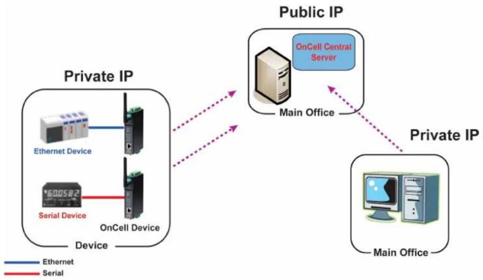
flowchart
graph TD
    A["Private IP"] -->|Ethernet Device| B["OnCell Device"]
    A -->|Serial Device| C["OnCell Device"]
    B --> D["Public IP"]
    C --> D
    D -->|OnCell Central Server| E["Main Office"]
    D -->|Main Office| F["Private IP"]
    style A fill:#f9f,stroke:#333
    style B fill:#ccf,stroke:#333
    style C fill:#cfc,stroke:#333
    style D fill:#fcc,stroke:#333
    style E fill:#cff,stroke:#333
    style F fill:#ffc,stroke:#333
OnCell Central Serial Device Connection
If your device is serial interface, and your cellular service provider assigns you a private IP address after you connect to the cellular network, Real COM, RFC2217, or TCP Server mode allow you to access the OnCell G3100 via an OnCell Central Server from host PC.
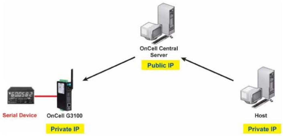
flowchart
graph TD
    A["Serial Device"] --> B["OnCell G3100"]
    B --> C["OnCell Central Server"]
    C --> D["Host"]
    B -->|Private IP| C
    B -->|Private IP| D
OnCell Central Ethernet Device Connection
If your device is Ethernet interface, and your cellular service provider assigns you a private IP address after you connect to the cellular network, service forwarding allows you to access the OnCell G3100 via an OnCell Central Server from any host PC using either a private IP or public IP address.
Service forwarding, sometimes referred to as port mapping, is the act of forwarding a network port from one network node to another. This technique can allow an external user to reach a port on a private IP address (inside a LAN) from the outside via a NAT-enabled IP gateway (OnCell G3100's NAT original is enabled).
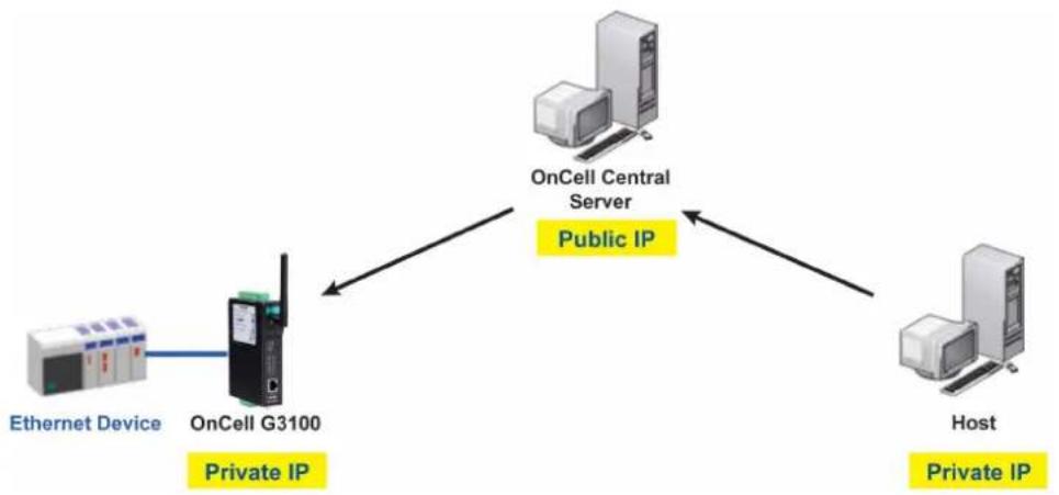
flowchart
graph TD
    A["Ethernet Device"] -->|Private IP| B["OnCell G3100"]
    B --> C["OnCell Central Server"]
    C --> D["Host"]
    B -->|Public IP| C
    D -->|Private IP| C
Cellular-Enabling Ethernet Device
The OnCell G3100 IP gateway works like a router. All Ethernet devices connected to the OnCell's LAN port are hidden via the OnCell's NAT function. This allows any number of local Ethernet devices to access the Internet using the OnCell as a gateway. However, the OnCell G3100 appears as just a single IP address on the Internet. Therefore, incoming connections must be manually forwarded from the OnCell's public TCP port number to the internal ports of the local Ethernet devices. Please refer to Chapter 9, Configuring Cellular-Enabling Ethernet Device.
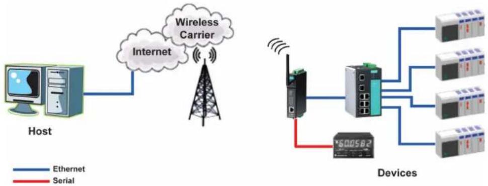
flowchart
graph TD
    A["Host"] --> B["Internet"]
    B --> C["Wireless Carrier"]
    C --> D["Device 1"]
    C --> E["Device 2"]
    C --> F["Device 3"]
    C --> G["Device 4"]
    C --> H["Device 5"]
    C --> I["Device 6"]
    style A fill:#f9f,stroke:#333
    style B fill:#ccf,stroke:#333
    style C fill:#cfc,stroke:#333
    style D fill:#fcc,stroke:#333
    style E fill:#cff,stroke:#333
    style F fill:#ffc,stroke:#333
    style G fill:#cfc,stroke:#333
    style H fill:#fcc,stroke:#333
    style I fill:#ffc,stroke:#333
Virtual Modem Mode
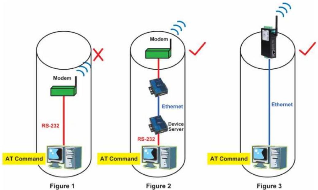
Note: This function is only supported by the OnCell G3100 HW Rev. 2.0 and Rev. 3.0. Please refer to the Specifications section of Chapter 1 (page 1-3) for more information.
Virtual Modem mode is designed for AT command operating system devices. Its purpose is to extend the limited RS-232 cabling distance between computers and modems (Figure 1). The setup in Figure 2 is not an efficient architecture because we need to deploy extra devices to bridge the gap. A more efficient solution is provided in Figure 3. By taking advantage of the cable length of Ethernet cables, connecting a properly configured OnCell IP gateway's Ethernet port to the device computer's Ethernet port and installing the Moxa driver, users can transmit data over a cellular network with software originally designed to transmit data through a modem. Please refer to Chapter 10, Configuring Virtual Modem Mode.
The web console is the most user-friendly method available to configure the OnCell G3100. With a standard web browser, you have easy and intuitive access to all settings and options. In this chapter, we introduce the web console and go through the basic configuration options. The same configuration options are also available through the Telnet and serial console.
The following topics are covered in this chapter:
□ Using Your Web Browser
▶ Browser Cookie Settings
Trusted Site Settings
Opening the Web Console
□ Web Console Navigation
□ Basic Settings
Server Settings
Time Settings
□ Network Settings
Basic Network Settings
DNS Settings
▶ Advanced Network Settings
▶ Auto IP Report Settings
□ GuaranLink Settings
Overview
Background
Common Settings
▶ GuaranLink Check Settings
Using Your Web Browser
Browser Cookie Settings
Verify that cookies are enabled for your browser. If the cookies are disabled, you will not be able to use the web console. (Cookies are only used for password transmission.)
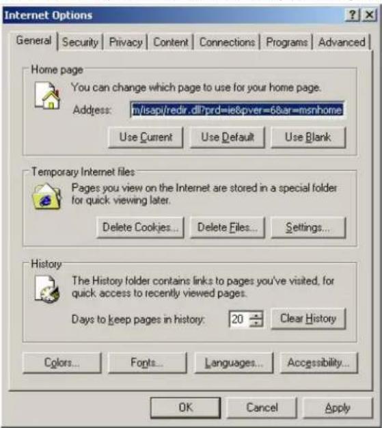
- For Internet Explorer, enable cookies by selecting Internet Options from the Tools menu:
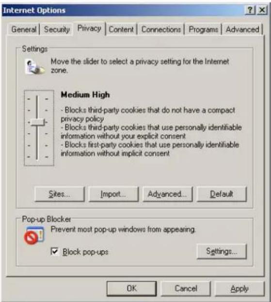
- Select the Privacy tab. There are six levels of privacy setting: Block All Cookies, High, Medium High, Medium, Low, and Accept All Cookies. Users must select Medium High (as the image shows) or below to access the OnCell G3100 web console.

ATTENTION
If you are not using Internet Explorer, cookies are usually enabled through a web browser setting such as "allow cookies that are stored on your computer" or "allow per-session cookies."
Trusted Site Settings
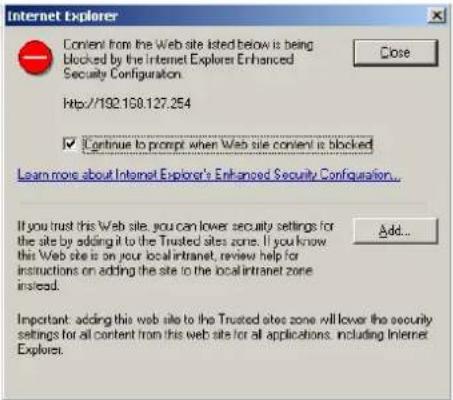
Windows 2003 users may need to add the OnCell G3100's IP address to their browser's list of trusted sites.
- If you see the following window while attempting to view the web console, click on Add to modify the list of trusted sites.
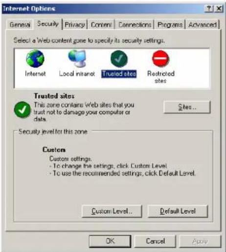
You may also access the list of trusted sites directly through Internet Options in the Tools menu of Internet Explorer. Select the Security tab, click on the Trusted Sites icon, and then select the Sites button.
- In either case, the window below should appear, showing the list of sites that you have configured Internet Explorer to trust. Add the IP address of your OnCell G3100 here (the factory default IP address is 192.168.127.254).
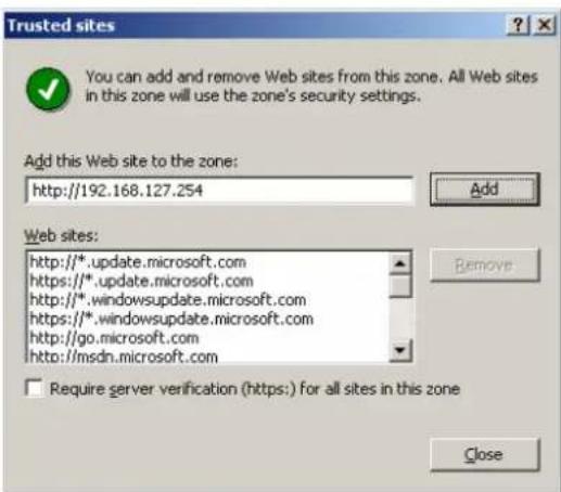
After adding the OnCell G3100's IP address as a trusted site, you should be able to view the web console by entering the OnCell G3100's IP address in your browser's address bar.
Opening the Web Console
Open your web browser and enter 192.168.127.254 in the website address line. This is the default IP address for the OnCell G3100—if a new address has been assigned, enter the new address instead. Press ENTER to load the page.

ATTENTION
The examples and figures in this chapter use the OnCell G3100 factory default IP address of 192.168.127.254. If you have assigned a different IP address to your OnCell G3100, be sure to adjust accordingly when following these directions. Please refer to Chapter 3, Initial IP Address Configuration, for details on how to configure the IP address.
Enter the console password if prompted. (This will not apply if you did not enable password protection for your OnCell G3100.) The password will be transmitted with MD5 encryption over the Internet.
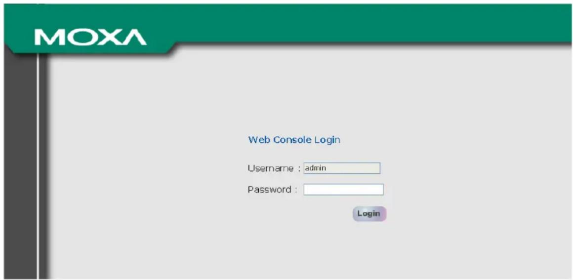

ATTENTION
If you forget your password, the ONLY way to configure the OnCell G3100 is by using the reset button to reset all settings and load the factory defaults. If you have disabled the reset button in your OnCell G3100 configuration, you may still use it to load the factory defaults within the first 60 seconds that the OnCell G3100 is powered on.
Remember to back up your configuration by exporting it to a file. Your configuration can be easily restored by importing the file to the OnCell G3100. This will save time if you have forgotten the password and need to reload the factory defaults.
The OnCell G3100's web console will appear.
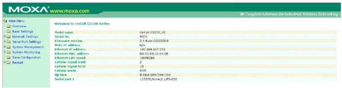

ATTENTION
In the Overview page you will find general information about the device such as firmware version, IP address and signal RSSI. In particular, the RSSI value displayed here can be mapped to the dBm value specific to the cellular module used for the OnCell:
| RSSI | dBm | RSSI | dBm | |
| 0 | -113 dBm or less | 16 | -81 dBm | |
| 1 | -111 dBm | 17 | -79 dBm | |
| 2 | -109 dBm | 18 | -77 dBm | |
| 3 | -107 dBm | 19 | -75 dBm | |
| 4 | -105 dBm | 20 | -73 dBm | |
| 5 | -103 dBm | 21 | -71 dBm | |
| 6 | -101 dBm | 22 | -69 dBm | |
| 7 | -99 dBm | 23 | -67 dBm | |
| 8 | -97 dBm | 24 | -65 dBm | |
| 9 | -95 dBm | 25 | -63 dBm | |
| 10 | -93 dBm | 26 | -61 dBm | |
| 11 | -91 dBm | 27 | -59 dBm | |
| 12 | -89 dBm | 28 | -57 dBm | |
| 13 | -87 dBm | 29 | -55 dBm | |
| 14 | -85 dBm | 30 | -53 dBm | |
| 15 | -83 dBm | 31 | -51 dBm or greater |
Web Console Navigation
The left panel of the OnCell G3100's web console is the navigation panel, and contains an expandable menu tree for navigating among the various settings and categories. When you click on a menu item in the navigation panel, the main window will display the corresponding options for that item. Configuration changes can then be made in the main window. For example, if you click on Basic Settings in the navigation panel, the main window will show a page of basic settings that you can configure.
You must click on the Submit button to keep your configuration changes. The Submit button will be located at the bottom of every page that has configurable settings. If you navigate to another page without clicking the Submit button, your settings will not be retained.
Changes will not take effect until they are saved and the OnCell is restarted! You may complete this in one step by clicking on the Save/Restart option after you submit a change. If you need to make several changes before restarting, you may save your changes without restarting by selecting Save Configuration in the navigation panel. If you restart the OnCell G3100 without saving your configuration, the OnCell G3100 will discard all submitted changes.
Basic Settings
The Basic Settings screen can be accessed from the navigation panel.
Server Settings
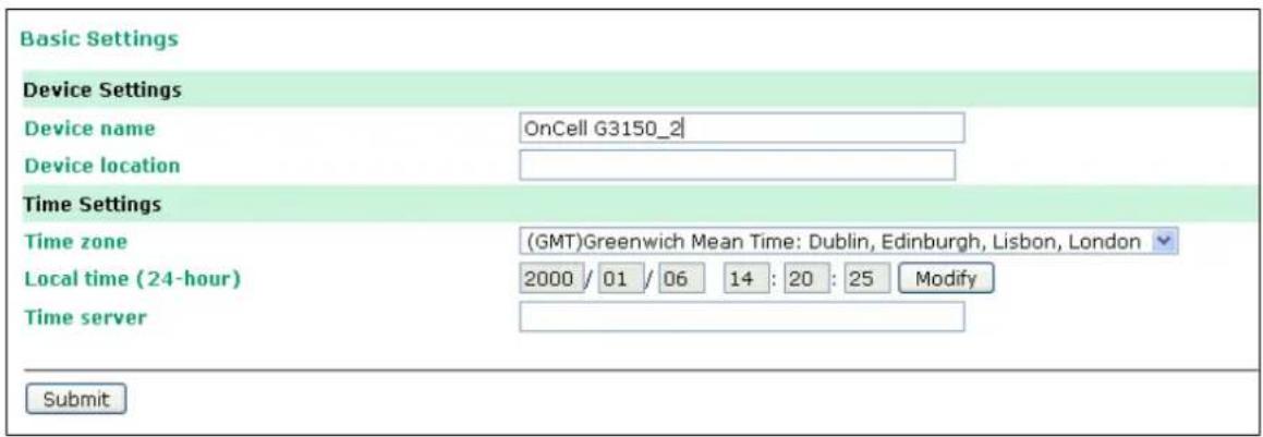
Device name: This is an optional free text field for your own use; it does not affect the operation of the OnCell G3100, and can be used to help differentiate one OnCell G3100 server from another.
Device location: This is an optional free text field for your own use; it does not affect the operation of the OnCell G3100, and is useful for assigning or describing the location of an OnCell G3100. In a network environment of multiple servers, this can be a valuable aid when doing maintenance.
Time Settings
The OnCell G3100 has a built-in Real-Time Clock for time calibration functions. Functions such as Auto Warning Email or SNMP Trap can add real-time information to messages.
Before making any adjustments to the time, first select the correct time zone and submit the change. The console will display the real time according to the time zone. To modify the real time clock, click on Modify next to the Local time field. Once you submit the new time, the OnCell G3100's firmware will modify the GMT time according to your time zone and local time settings.

ATTENTION
There is a risk of explosion if the real-time clock battery is replaced with the wrong type! The OnCell G3100's real time clock is powered by a lithium battery. We strongly recommend that you do not attempt to replace the lithium battery without help from a qualified Moxa support engineer. If you need to change the battery, please contact the Moxa RMA service team.
Time zone (default= GMT Greenwich Mean Time): This field shows the currently selected time zone and allows you to select a different time zone.
Local time: This field shows the time that you last opened or refreshed the browser. To set the local time for the OnCell G3100, click on the Modify button, update the date and time, and then click on submit.
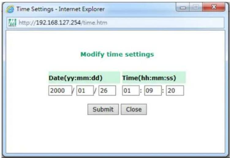
Time server: The OnCell G3100 uses SNTP (RFC-1769) for auto time calibration. You may enter a time server IP address or domain name in this optional field. Once the OnCell G3100 is configured with the correct time server address, it will request time information from the time server every 10 minutes.
Network Settings
Basic Network Settings
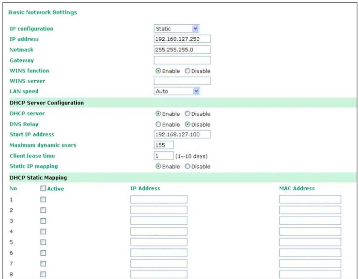
You can access Basic Network Settings by expanding the Network Settings item in the navigation panel. Basic Network Settings is where you assign the OnCell G3100's IP address, netmask, Gateway, and other parameters for the Ethernet interface.
NOTE
You must assign a valid IP address to your OnCell G3100 before it will work in your network environment. Your network system administrator should provide you with a unique IP address and related settings for your network. First-time users can refer to Chapter 3: Initial IP Address Configuration, for more information.
IP configuration (default=Static): You can choose from four possible IP configuration modes.
| Option Description | |
| Static | User-defined IP address, netmask, and gateway. |
| DHCP | DHCP server-assigned IP address, netmask, gateway, and DNS |
| DHCP/BOOTP | DHCP server-assigned IP address, netmask, gateway, and DNS, or BOOTP server-assigned IP address (if the DHCP server does not respond) |
| BOOTP | BOOTP server-assigned IP address |
IP Address (default=192.168.127.254): Enter the IP address that will be assigned to your OnCell G3100. All ports on the OnCell G3100 will share this IP address. An IP address is a number assigned to a network device (such as a computer) as a permanent address on the network. Computers use the IP address to identify and talk to each other over the network. Choose a proper IP address that is unique and valid for your network environment.
Netmask (default=255.255.255.0): Enter the subnet mask. A subnet mask represents all of the network hosts at one geographic location, in one building, or on the same local area network. When a packet is sent out over the network, the OnCell G3100 will use the subnet mask to check whether the desired TCP/IP host specified in the packet is on the local network segment. If the address is on the same network segment as the OnCell G3100, a connection is established directly from the OnCell G3100. Otherwise, the connection is established through the given default gateway.
Gateway: Enter the IP address of the gateway if applicable. A gateway is a network computer that acts as an entrance to another network. Usually, the computers that control traffic within the network or at the local Internet service provider are gateway nodes. The OnCell G3100 needs to know the IP address of the default gateway computer in order to communicate with the hosts outside the local network environment. For correct gateway IP address information, consult the network administrator.

ATTENTION
In dynamic IP environments, the firmware will try to get the network settings from the DHCP or BOOTP server 3 times every 30 seconds until network settings are assigned by the DHCP or BOOTP server. The first try times out after 1 second, the second after 3 seconds, and the third after 5 seconds.
If the DHCP/BOOTP server is unavailable, the firmware will use the default IP address (192.168.127.254), netmask, and gateway settings.
WINS function (default=enable): Enable or disable the WINS (Windows Internet Naming Service) server.
WINS Server: If a WINS Server is connected to the network, enter the WINS Server IP address in this field. TCP/IP uses IP addresses to identify hosts, but users often use symbolic names, such as computer names. The WINS Server, which uses NetBIOS over TCP/IP, contains a dynamic database to map computer names to IP addresses.
LAN speed (default=Auto): You may configure the network speed for the built-in Ethernet connection on the OnCell G3100. IEEE802.3 Ethernet supports auto negotiation of transfer speed. However, some switches/hubs require that the communication speed be fixed at 100 Mbps or 10 Mbps.
DHCP (default=Enable): DHCP stands for Dynamic Host Control Protocol. When you enable the DHCP Server, it will automatically assign an IP address to the computers on the LAN or private network. Be sure to set your computers to be DHCP clients by setting their TCP/IP settings to "Obtain an IP Address Automatically." When you turn your computers on, they will automatically load the proper TCP/IP settings provided by the OnCell 5000. The DHCP Server will automatically allocate an unused IP address from the IP address pool to the requesting computer. You must specify the starting and ending address of the IP address pool.
DNS relay (default=Enable): If you enable DNS relay, your computers will use the router as a DNS server. If you disable DNS relay, transfer the DNS server information from your ISP to your computers.
Start IP address: Enter the starting IP addresses for the DHCP server's IP assignment.
Maximum dynamic users: Enter the number of dynamic users. The maximum users you can enter may not exceed 253, if your dynamic IP address begins with 192.168.127.1
Note: If you statically (manually) assign IP addresses to your computers or devices, make sure the IP addresses are outside of this range or you may have an IP conflict.
Client lease time: The length of time for the IP address lease. Enter the Lease time in minutes.
Static IP mapping: If enabled, the mapping list allows you to assign the DHCP IP within the range to your specific device from MAC address.
DNS Settings
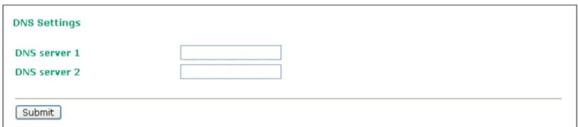
DNS server 1: This is an optional field. If your network has access to a DNS server, you may enter the DNS server's IP address in this field. This allows the OnCell 5000 to use domain names instead of IP addresses to access hosts.
The Domain Name System (DNS) is used to identify Internet domain names, and translate the names into IP addresses. A domain name is an alphanumeric name, such as www.moxa.com, that it is usually easier to remember than the numeric IP address. A DNS server is a host that translates this kind of text-based domain name into the actual IP address used to establish a TCP/IP connection.
When the user wants to visit a particular website, the user's computer sends the domain name (e.g., www.moxa.com) to a DNS server to request that website's numeric IP address. When the IP address is received from the DNS server, the user's computer uses that information to connect to the website's web server. The OnCell 5000 plays the role of a DNS client, in the sense that it actively queries the DNS server for the IP address associated with a particular domain name. The following functions in the OnCell 5000's web console support the use of domain names in place of IP addresses: Time Server, Destination IP Address (in TCP Client mode), Mail Server, SNMP Trap Server, and SMTP Server.
DNS server 2: This is an optional field. The IP address of another DNS server may be entered in this field for times when DNS server 1 is unavailable.
Advanced Network Settings
Access Advanced Network Settings by expanding the Network Settings item in the navigation panel. Advanced Network Settings is where the gratuitous ARP is configured.

Gratuitous ARP: In some applications, you may need the OnCell G3100 to send broadcast packets to update the ARP table on the server. If you enable this function and set the send period, the OnCell G3100 will periodically send broadcast packets at the specified time interval.
Auto IP Report Settings
Access Auto IP Report Settings by expanding the Network Settings item in the navigation panel.
When the OnCell G3100 products are used in a dynamic IP environment, users must spend more time with IP management tasks. For example, if the OnCell works as a server (TCP or UDP), then the host, which acts as a client, must know the IP address of the server. If the DHCP server assigns a new IP address to OnCell, the host must have some way of determining OnCell's new IP address.
OnCell G3100 products help out by periodically reporting their IP address to the IP location server, in case the dynamic IP has changed. The parameters shown below are used to configure the Auto IP report function. There are two ways to develop an "Auto IP report Server" to receive the OnCell's Auto IP report.
Use the OnCell Search Utility's IP Address Report function. Please refer to OnCell Search Utility Configuration in Chapter 15.
"Auto IP report protocol," which can automatically receive the Auto IP report on a regular basis, is also available to help you develop your own software. Refer to Appendix E for the "Auto IP report protocol."
Network Settings - Auto IP Report
Configuration
Auto IP report to host
Report to UDP port
Report period
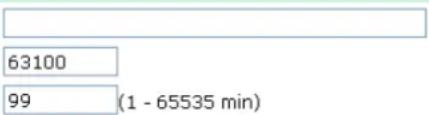
Submit
Auto IP report to host: Reports generated by the Auto report function will be sent automatically to this IP address or host name.
Report to UDP port (default=63100): This is the UDP port number assignment for the serial port on the OnCell G3100.
Report period (default=99): You can use this option to set how often the IP address is automatically reported.

ATTENTION
To use the OnCell Search Utility to receive the auto IP report message sent from the OnCell G3100, please also install Windows Driver Manager. Windows Driver Manger helps dispatch messages to the OnCell Search Utility.
GuaranLink Settings
Overview
Connection failures of wireless connections can be caused by a number of different factors, including loss of cellular signal, interference, or termination by the operator for unknown reasons. Typically, cellular routers will not be alerted when a connection is terminated due to inactivity. Since maintaining a stable cellular connection is important for a number of obvious reasons, OnCell cellular routers offer the GuaranLink function, which ensures that your wireless connection will be there whenever you need it.
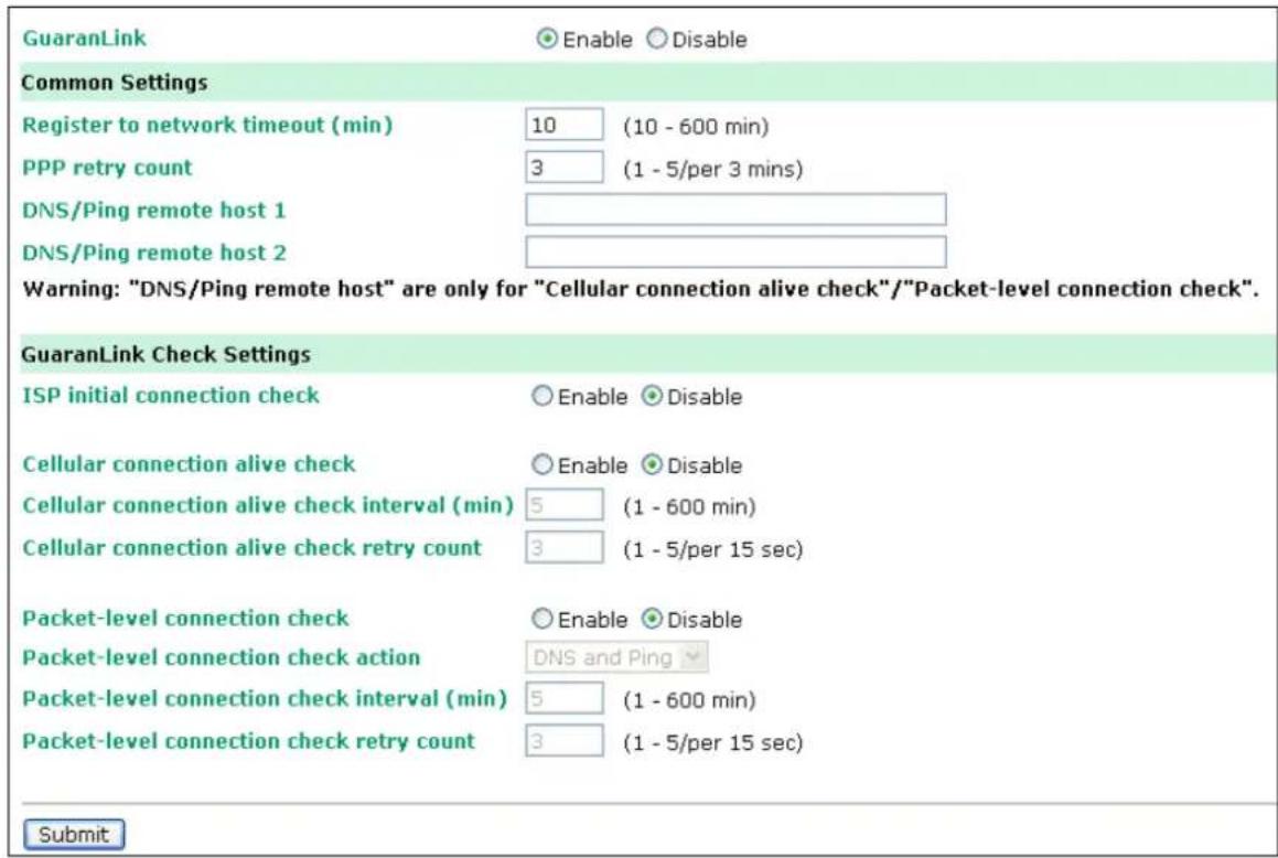
Background
"Register to network" and "Establish PPP with ISP" are two steps for establishing connection with the ISP.
If GuaranLink determines that the OnCell cannot establish a connection with the ISP, it reboots the OnCell in order to allow the OnCell to retry the connection once it reboots.
Common Settings
GuaranLink (default=Disable): Enable this setting to start the GuaranLink function.
Register to network timeout (min) (default=10): This setting specifies how long GuaranLink should wait to register to the network before the OnCell reboots itself.
PPP retry count (default=3 mins) This setting specifies how many times GuaranLink should retry establishing PPP with the ISP before OnCell reboots itself.
DNS/ Ping remote host 1 and DNS/ Ping remote host 2: This setting is for "Cellular connection alive check" and "Packet-level connection check." It specifies the target host of the DNS lookup and Ping action. Can be either a domain name or an IP address.
GuaranLink Check Settings
ISP initial connection check (default=Disable): This function ensures that the OnCell can establish a connection with an ISP after it reboots.
Cellular connection alive check (default=Disable): Some ISPs may disable the connection if no data is transmitted in a specific period of time. This function ensures that the cellular connection will be kept alive even if no data is transmitted for a period of time by performing the check action of DNS lookup or ping action of DNS/Ping remote host 1 or DNS/Ping remote host 2. If the check action fails after the retry count number specified in "Cellular connection alive check retry count", the OnCell will re-establish a connection with the ISP.
Cellular connection alive check interval (min) (default=5 min): This setting specifies the idle time before GuaranLink performs the check action.
Cellular connection alive check retry count (default=3 sec): This setting specifies the number of attempts to reach the remote target(s) before the OnCell re-establishes a connection.
Packet-level connection check (default=Disable): This function checks if the cellular network can be accessed by performing the check action of lookup DNS or ping action of DNS/Ping remote host 1 or DNS/Ping remote host 2. If the check action fails after the retry count number specified in "Packet-level connection check retry count." the OnCell will re-establish a connection with ISP.
Packet-level connection check action (default=DNS and PING): This setting specifies whether the check action is successful when both of the DNS lookup and the ping action succeed, or if it is successful even if only one of them succeed.
Packet-level connection check interval (min) (default=5 min): This setting specifies the interval between two check actions.
Packet-level connection check retry count (default=3 sec): This setting specifies the number of attempts to reach the remote target(s) before the OnCell re-establishes a connection.
In this chapter, we describe how to set up cellular networks, including GSM, GPRS, EDGE, UMTS, HSPA and SMS. The configuration options discussed here are also available from the Telnet and serial consoles.
The following topics are covered in this chapter:
☐ GSM GPRS Settings (For OnCell G3110 and G3150)
☐ Cellular Setting (OnCell G3110-HSPA and OnCell G3150-HSPA)
➢ GSM or GSM (CSD) Operation Mode
➢ GPRS or GPRS/EDGE/UMTS/HSPA Operation Mode
➢ SMS Operation mode
➢ Virtual Modem Operation mode
GSM GPRS Settings (For OnCell G3110 and G3150)
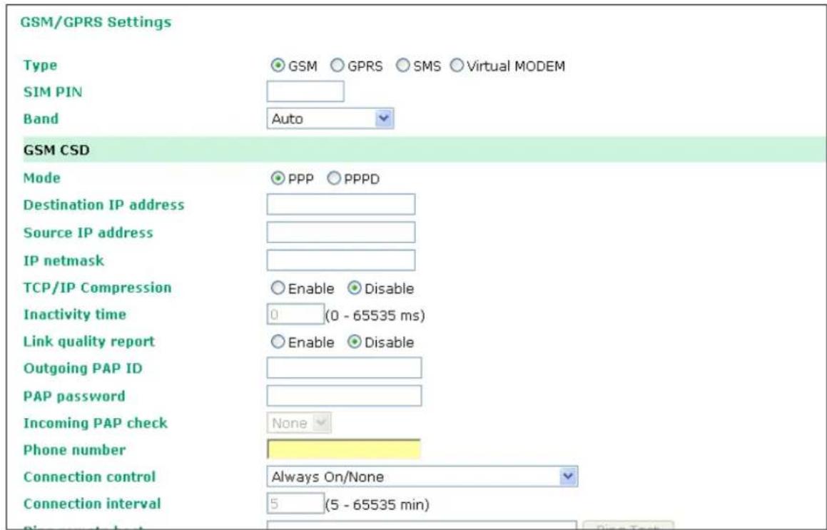
From the left navigation panel, click Network Settings → GSM GPRS Settings to configure the GSM/GPRS/SMS Settings. The various configuration items are described below:
Type: The OnCell G3100 supports 3 types of operation modes. You may choose from GSM, GPRS, and SMS.
SIM PIN: This is a pin code that locks the SIM card until you enter the correct code. Use the pin to protect your account. The default code is set by the Service Provider. Note that a cell phone must be used to change the PIN.
Selecting the Radio Band: Although GSM-900 and GSM-1800 are used in most parts of the world, operators in United States, Canada, and many other countries in the Americas use GSM-850 or GSM-1900. The GSM/GPRS band of GSM/GPRS/EDGE module is configured to auto by default.
Additional settings for each of the three modes are described in the following subsections.
Cellular Setting (OnCell G3110-HSPA and OnCell G3150-HSPA)

From the left navigation panel, click Network Settings → Cellular Settings to configure the GSM/GPRS/EDGE/UMTS/HSPA/SMS Settings. The various configuration items are described below:
Type: The OnCell G3100 supports 3 types of operation mode. You may choose from GSM (CSD), GPRS/EDGE/UMTS/HSPA, and SMS.
SIM PIN: This is a pin code that locks the SIM card until you enter the correct code. Use the pin to protect your account. The default code is set by the Service Provider. Note that a cell phone must be used to change the PIN.
Selecting the Radio Band: Although GSM-900 and GSM-1800 are used in most parts of the world, operators in United States, Canada, and many other countries in the Americas use GSM-800, GSM-850, GSM-1900, AWS 1700, or GSM-2100. The GSM/GPRS/EDGE/UMTS/HSPA band for the module is configured to auto by default.
GSM or GSM (CSD) Operation Mode
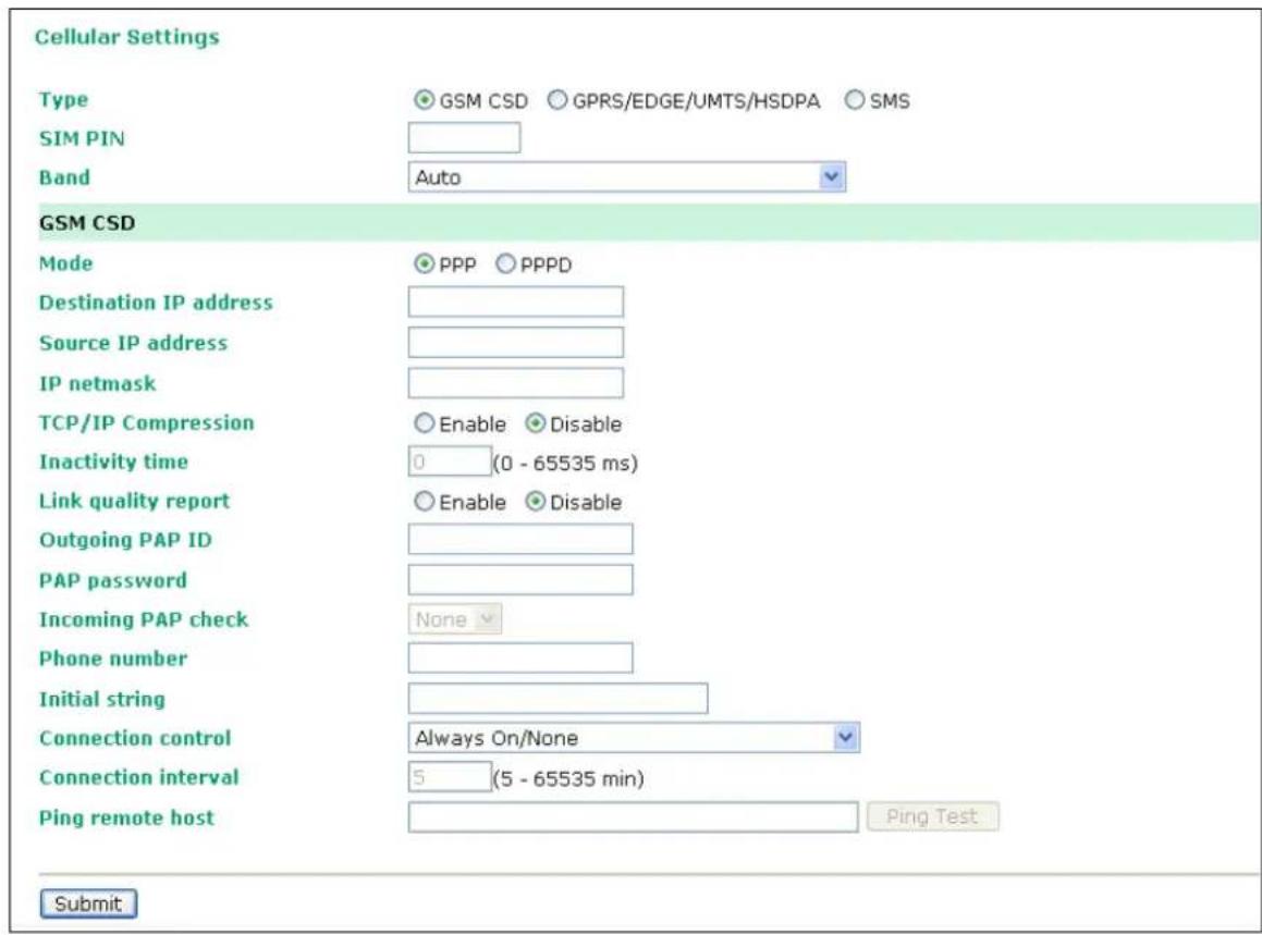
PPP Mode: PPP provides standard PPP dial-out service.
PPPD Mode: PPPD (PPP Daemon) is used for dial-in services, since it provides PPP services only when receiving a request from a remote PC.
Destination IP address, Source IP address, IP netmask: If you do not configure these three parameters, they will be filled in automatically by the remote side of the connection.
TCP/IP compression (default=Disable): The setting of this field depends on whether the remote user's application requests compression.
Inactivity time (default=0 ms): This field specifies the idle time setting for auto-disconnection. A setting of 0 ms will cause the port to remain connected even if idle.
Link quality report (default=Disable): Setting this field to Enable allows the OnCell G3100 to disconnect a connection if the link noise exceeds a certain threshold.
Outgoing PAP ID: This is the dial-out user ID account.
PAP password: This is the dial-out user password.
Incoming PAP check (default=None): This field allows you to configure the method used, if any, to verify a user's ID and authorization.
| Option Description | |
| Local | Verify the ID against the OnCell G3100 password. The user name for the OnCell G3100 is fixed to “admin.” |
| None | Authentication is not required. |
Phone number: Use this field to configure the number used to dial out.
Initial string: Use this field to configure the initial string that the IP gateway will use to establish the connection.
| Connection control | Connect Rule | Disconnect Rule | GSM |
| Always on/None | Always on after power on | None | Trunk |
| Periodically connect/inactivity time | Periodically connect (based on the connection interval setting) to GSM after power on. | Inactivity time is up Trunk | |
| Remote host fail/remote host recovered | Remote Ethernet host has failed. The OnCell G3100 will keep pinging the remote host over the Ethernet every 3 seconds after powering on. After failing to connect 5 times in a row, the data from the serial device will be sent through the GSM connection. | When the remote Ethernet host returns to normal, data will revert to being sent over Ethernet after 5 continuous successful pings. | Backup |
Connection interval (default= 5 min): The time interval of the periodically connect function.
Ping remote host: Key in the IP address or Domain name of the remote host.
GPRS or GPRS/ EDGE/ UMTS/ HSPA Operation Mode
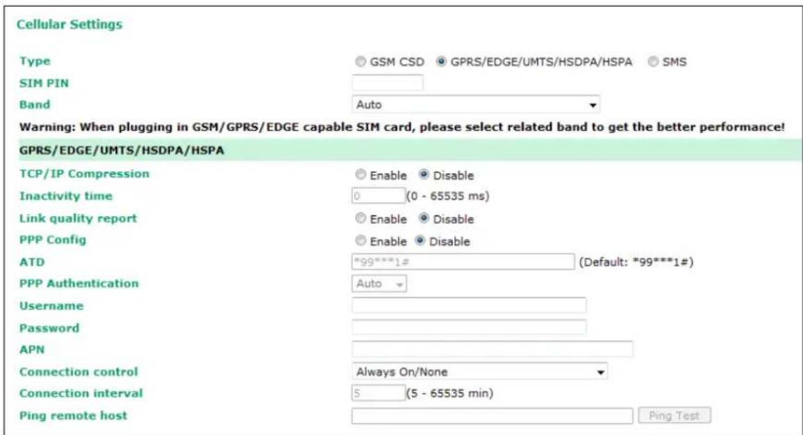
TCP/IP compression (default=Disable): The setting of this field depend on whether or not the remote user's application requests compression.
Inactivity time (default=0 ms): This field specifies the idle time setting for auto-disconnection. A setting of 0 ms will cause the port to remain connected even if idle.
Link quality report (default=Disable): Setting this field to Enable allows the OnCell G3100 to disconnect a connection if the link noise exceeds a certain threshold.
PPP Config: This option allows the user to manually configure PPP authentication methods. Some cellular providers may require users specify the dial-up number or PPP authentication method.
ATD: This is the number that the OnCell uses to dial onto the data network. Different countries may require different dial-up numbers (default: *99***1#).
PPP Authentication: manually select PAP or CHAP authentication methods or use AUTO for auto selection.
Username: This is the user ID account.
Password: This is the user password.
APN: Before using the GPRS/UMTS/HSPA also need APN (Access Point Name) must be added as an IP gateway initialization command. Detailed instructions are shown below.
| Connection control | Connect Rule | Disconnect Rule | GPRS |
| Always on/None | Always on after power on | None | Trunk |
| Periodically connect/inactivity time | Periodically connect (based on the connection interval setting) attempt to connect to UMTS/HSPA first then GPRS after powering on. | Inactivity time is up Trunk | |
| Remote host fail/remote host recovered | Remote Ethernet host has failed. The OnCell G3100 will keep pinging the remote host over the Ethernet every 3 seconds after powering on. After failing to connect 5 times in a row, the data from the serial device will be sent through the UMTS/HSPA first then GPRS connection. | When the remote Ethernet host returns to normal, data will revert to being sent over Ethernet after 5 continuous successful pings. | Backup |
Connection interval (default = 5 min): The time interval of the periodic connect function.
Ping remote host: Key in the IP address of the remote host.
SMS Operation mode
Short Message Service (SMS) is a telecommunications protocol that allows sending “short” (160 characters or less) text messages. It is available on most digital mobile phones and some personal digital assistants with built-in wireless capability.
GSM technology offers the benefit of using SMS (short message service) as an easy way to communicate over the mobile network. In the next chapter, we explain how to use SMS with the OnCell G3100.
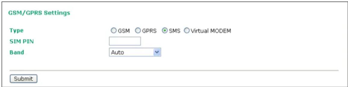
Virtual Modem Operation mode
Virtual Modem mode (only available for OnCell G3110/G3150) is designed for AT command operating system devices. For more details, please refer to Chapter 5 for an introduction and Chapter 10 for configuration settings.
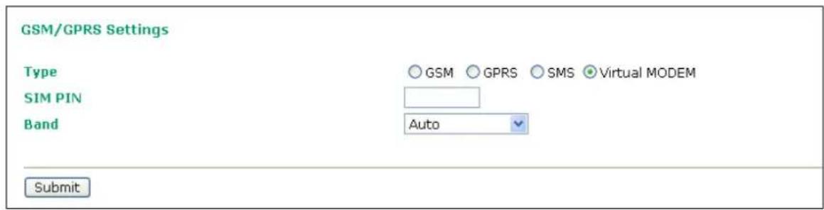
In this chapter, we explain how to configure the individual serial port modes.
The following topics are covered in this chapter:
□ Port Setting Basics
□ Device Control Applications
Real COM Mode
➢ Reverse Real COM Mode
RFC2217 Mode
□ Socket Applications
▶ TCP Server Mode
▶ TCP Client Mode
▶ UDP Mode
☐ Ethernet Modem Mode
□ SMS Tunnel Mode
□ Disabled Mode
Port Setting Basics
To configure the operation mode and settings for a port, expand Serial Port Settings in the navigation panel, and then expand the port that you would like to configure. Individual port settings are grouped into three categories in the navigation panel: Operation Modes, Communication Parameters, and Data Buffering/Log.
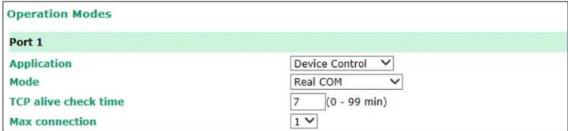
Select Operation Modes in the navigation panel to select and configure the mode for each serial port.
Application: Select an application for the serial port from among the choices. Your application will determine the modes that are available.
Mode: Once you have chosen an application, select the mode. The available configuration settings will vary depending on the mode that you have selected.
Device Control Applications
Real COM Mode
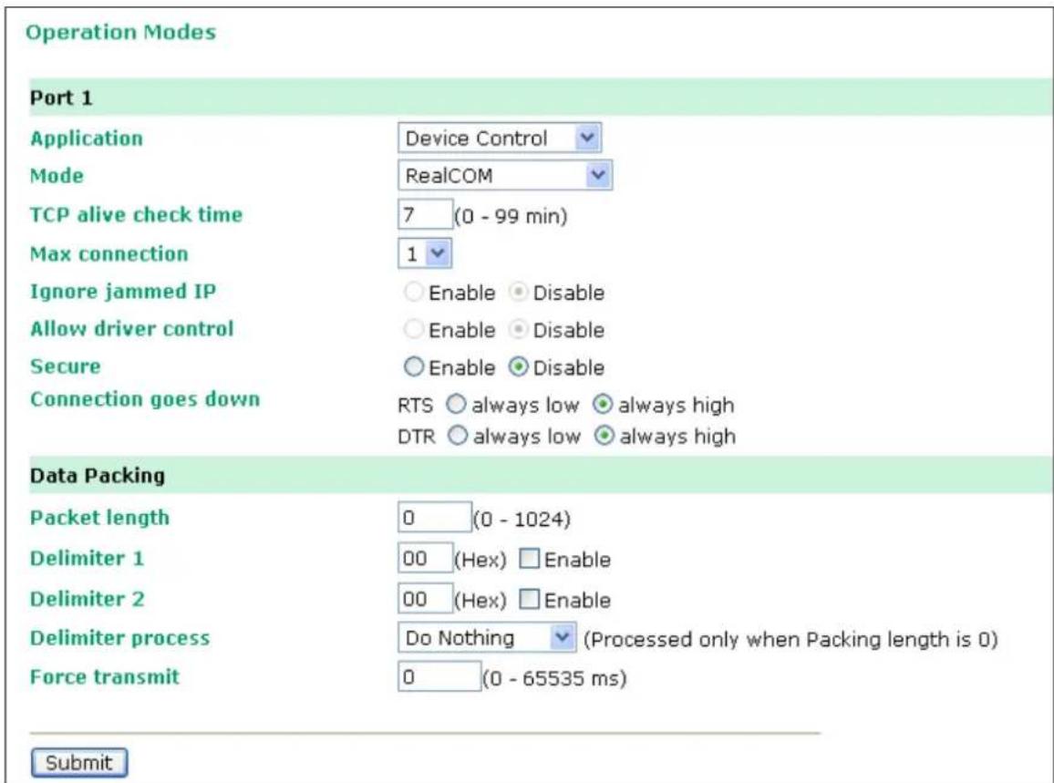
TCP alive check time (default=7 min): This field specifies how long the OnCell G3100 will wait for a response to "keep alive" packets before closing the TCP connection. The OnCell G3100 checks connection status by sending periodic "keep alive" packets. If the remote host does not respond to the packet within the time specified in this field, the OnCell G3100 will force the existing TCP connection to close. For socket and device control modes, the OnCell G3100 will listen for another TCP connection from another host after closing the connection. If TCP alive check time is set to 0, the TCP connection will remain open and will not send any "keep alive" packets.
Max connection (default=1): This field is used if you need to receive data from different hosts simultaneously. When set to 1, only one specific host can access this port of the OnCell G3100, and the OnCell COM driver on that host will have full control over the port. When set to 2, the specified number of hosts' OnCell COM driver may open this port at the same time. When multiple hosts' OnCell COM driver open the port at the same time, the COM driver only provides a pure data tunnel --no control ability unless "Allow Driver Control" is enabled. The serial port parameters will use firmware settings instead of depending on your application program (AP).
Application software that is based on the COM driver will receive a driver response of "success" when the software uses any of the Win32 API functions. The firmware will only send data back to the driver on the host.
Data will be sent first-in-first-out when data comes into the OnCell G3100 from the Cellular or Ethernet interface.

ATTENTION
When Max connection is greater than 1, the OnCell G3100 will use a multi connection application (i.e., 2 hosts are allowed access to the port at the same time). When using a multi connection application, the OnCell G3100 will use the serial communication parameters as defined here in the web console, and all hosts connected to the port must use identical serial settings. If one of the hosts opens the COM port with different serial settings, data will not be transmitted properly.
Ignore jammed IP (default=Disable): This option determines how the port will proceed if multiple hosts are connected and one or more of the hosts stops responding as the port is transmitting data. If you select Disable, the port will wait until the data has been transmitted successfully to all hosts before transmitting the next group of data. If you select Enable, the port will ignore the host that stopped responding and continue data transmission to the other hosts.
Allow driver control (default=Disable): This option determines how the port will proceed if driver control commands are received from multiple hosts that are connected to the port. If Disable is selected, driver control commands will be ignored. If Enable is selected, control commands will be accepted, with the most recent command received taking precedence.
Secure (default=Disable): If you select Enable, data sent through the Ethernet will be encrypted with SSL.

ATTENTION
If your OnCell G3100 serial port is in Real COM or Reverse Real COM mode and is configured for SSL encryption, make sure the COM driver is configured the same way. This is done with Windows Driver Manager, which is installed with the driver. Please refer to Chapter 14, Software Installation/Configuration, for more information.
Connection goes down (default=always high): You can configure what happens to the RTS and DTR signals when the Cellular or Ethernet connection goes down. For some applications, serial devices need to know the Cellular or Ethernet link status through RTS or DTR signals sent through the serial port. Use “always low” if you want the RTS and DTR signal to change their state to low when the Cellular or Ethernet connection gets disconnected. Use “always high” if you do not want the cellular or Ethernet connection status to affect the RTS or DTR signals.
Packet length (default=0): The Packet length setting refers to the maximum amount of data that is allowed to accumulate in the serial port buffer before sending. At the default of 0 for packet length, no maximum amount is specified and data in the buffer will be sent as specified by the delimiter settings or when the buffer is full. When a packet length between 1 and 1024 bytes is specified, data in the buffer will be sent as soon it reaches the specified length.
Delimiter 1 and Delimiter 2 (default=None): When Delimiter 1 is enabled, the serial port will queue the data in the buffer and send the data to the Cellular or Ethernet port when a specific character, entered in hex format, is received. A second delimiter character may be enabled and specified in the Delimiter 2 field, so that both characters act as the delimiter to control when data should be sent.

ATTENTION
In order to enable a delimiter, packet length must be set to 0. Delimiter 2 should only be enabled in conjunction with Delimiter 1 and never on its own; otherwise there may be data errors. Even when a delimiter is enabled, the OnCell G3100 will still pack and send the data when the amount of data exceeds 1 KB.
Delimiter process (default=Do Nothing): The Delimiter process field determines how the data is handled when a delimiter is received. Delimiter 1 must be enabled for this field to have effect. If Delimiters 1 and 2 are both enabled, both characters must be received for the delimiter process to take place.
- Do Nothing: Data in the buffer will be transmitted when the delimiter is received.
- Delimiter + 1: Data in the buffer will be transmitted after 1 additional byte is received following the delimiter.
- Delimiter + 2: Data in the buffer will be transmitted after 2 additional bytes are received following the delimiter.
- Strip Delimiter: Data in the buffer is first stripped of the delimiter before being transmitted.
Force transmit (default=0 ms): This parameter defines how large a gap in serial communication the OnCell G3100 will allow before packing the serial data in its internal buffer for network transmission.
As data is received through the serial port, it is stored by the OnCell G3100 in the internal buffer. The OnCell G3100 transmits data stored in the buffer via TCP/IP, but only when the internal buffer is full or as specified by the force transmit time. When set to 0, the force transmit time is disabled, and transmission is determined solely by the data in the internal buffer. At 1 to 65535, the TCP/IP protocol software will pack the serial data received after there is a gap in serial communication that exceeds the specified force transmit time.
The optimal force transmit time depends on your application, but it must be at least larger than one character interval within the specified baudrate. For example, assume that the serial port is set to 1200 bps, 8 data bits, 1 stop bit, and no parity. In this case, the total number of bits needed to send a character is 10 bits, and the time required to transfer one character is
$$ (1 0 (\text { bits }) / 1 2 0 0 (\text { bits } / \text { s })) \times 1 0 0 0 (\text { ms } / \text { s }) = 8. 3 \text { ms }. $$
Therefore, you should set the force transmit time to be greater than 8.3 ms, so in this case, it must be greater than or equal to 10 ms.
If it is necessary to send a series of characters in the same packet, the serial device will need to send that series of characters within the specified force transmit time, and the total length of data must be less than or equal to the OnCell G3100's internal buffer size (1 KB per port).
Reverse Real COM Mode
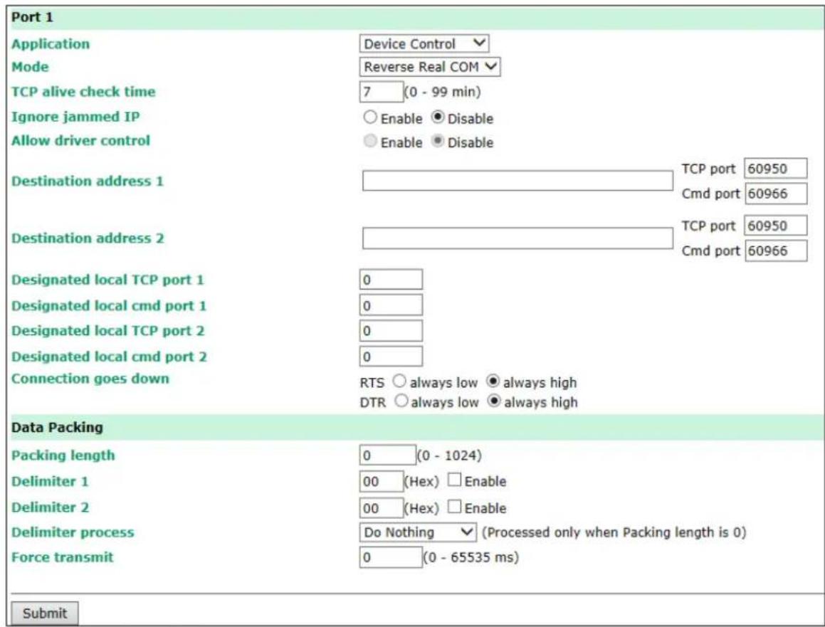
TCP alive check time (default=7 min): This field specifies how long the OnCell G3100 will wait for a response to "keep alive" packets before closing the TCP connection. The OnCell G3100 checks the connection status by sending periodic "keep alive" packets. If the remote host does not respond to the packet within the time specified in this field, the OnCell G3100 will force the existing TCP connection to close. For socket and device control modes, the OnCell G3100 will listen for another TCP connection from another host after closing the connection. If TCP alive check time is set to 0, the TCP connection will remain open and will not send any "keep alive" packets.
Ignore jammed IP (default=Disable): This option determines how the port will proceed if multiple hosts are connected and one or more of the hosts stops responding as the port is transmitting data. If you select Disable, the port will wait until the data has been transmitted successfully to all hosts before transmitting the next group of data. If you select Enable, the port will ignore the host that stopped responding and continue data transmission to the other hosts.
Allow driver control (default=Disable): This option determines how the port will proceed if driver control commands are received from multiple hosts that are connected to the port. If Disable is selected, driver control commands will be ignored. If Enable is selected, control commands will be accepted, with the most recent command received taking precedence.
Secure (default=No): If you select Yes, data sent through the Ethernet will be encrypted with SSL.

ATTENTION
If your OnCell G3100 serial port is in Reverse Real COM mode and is configured for SSL encryption, make sure the OnCell COM driver is configured the same way. Please refer to Chapter 14, Software Installation/Configuration, for more information.
Destination address 1 through 2 (default=None): Specifying an IP address allows the OnCell G3100 to connect actively to the remote host. At least one destination must be provided.
TCP port (default=60950): This is the TCP port number assignment for the remote host/server. It is the port number that the OnCell G3100's serial port uses to establish connections with a remote host/server. To avoid conflicts with well known TCP ports, the default is set to 60950.
Command port (default=60966): The Command port is the COM port for listening to SSDK commands from the host. In order to prevent a COM port conflict with other applications, the user can set the Command port to another port if needed.

ATTENTION
Up to 2 connections can be established between OnCell G3100 hosts.
Port 60950 might be blocked by a firewall. You should make sure the port is NOT blocked before you start using it.

ATTENTION
The destination IP address parameter can be the IP address, domain name, or the name defined in the host table.
Designated local port 1 through 2 (default=7010 through 7320): Use these fields to specify the designated local ports.
Connection goes down (default=always high): You can configure what happens to the RTS and DTR signals when the Cellular or Ethernet connection goes down. For some applications, serial devices need to know the Cellular or Ethernet link status through RTS or DTR signals sent through the serial port. Use “always low” if you want the RTS and DTR signal to change their state to low when the Cellular or Ethernet connection gets disconnected. Use “always high” if you do not want the cellular or Ethernet connection status to affect the RTS or DTR signals.
Packet length (default=0): The Packet length setting refers to the maximum amount of data that is allowed to accumulate in the serial port buffer before sending. At the default of 0 for packet length, no maximum amount is specified and data in the buffer will be sent as specified by the delimiter settings or when the buffer is full. When a packet length between 1 and 1024 bytes is specified, data in the buffer will be sent as soon it reaches the specified length.
Delimiter 1 and Delimiter 2 (default=None): When Delimiter 1 is enabled, the serial port will queue the data in the buffer and send the data to the Cellular or Ethernet port when a specific character, entered in hex format, is received. A second delimiter character may be enabled and specified in the Delimiter 2 field, so that both characters act as the delimiter to control when data should be sent.

ATTENTION
In order to enable a delimiter, packet length must be set to 0. Delimiter 2 should only be enabled in conjunction with Delimiter 1 and never on its own; otherwise there may be data errors. Even when a delimiter is enabled, the OnCell G3100 will still pack and send the data when the amount of data exceeds 1 KB.
Delimiter process (default=Do Nothing): The Delimiter process field determines how the data is handled when a delimiter is received. Delimiter 1 must be enabled for this field to have effect. If Delimiters 1 and 2 are both enabled, both characters must be received for the delimiter process to take place.
- Do Nothing: Data in the buffer will be transmitted when the delimiter is received.
- Delimiter + 1: Data in the buffer will be transmitted after 1 additional byte is received following the delimiter.
- Delimiter + 2: Data in the buffer will be transmitted after 2 additional bytes are received following the delimiter.
- Strip Delimiter: Data in the buffer is first stripped of the delimiter before being transmitted.
Force transmit (default=0 ms): This parameter defines how large a gap in serial communication the OnCell G3100 will allow before packing the serial data in its internal buffer for network transmission.
As data is received through the serial port, it is stored by the OnCell G3100 in the internal buffer. The OnCell G3100 transmits data stored in the buffer via TCP/IP, but only when the internal buffer is full or as specified by the force transmit time. When set to 0, the force transmit time is disabled, and transmission is determined solely by the data in the internal buffer. At 1 to 65535, the TCP/IP protocol software will pack the serial data received after there is a gap in serial communication that exceeds the specified force transmit time.
The optimal force transmit time depends on your application, but it must be at least larger than one character interval within the specified baudrate. For example, assume that the serial port is set to 1200 bps, 8 data bits, 1 stop bit, and no parity. In this case, the total number of bits needed to send a character is 10 bits, and the time required to transfer one character is
(10 (bits) / 1200 (bits/s)) × 1000 (ms/s) = 8.3 ms.
Therefore, you should set the force transmit time to be greater than 8.3 ms, so in this case, it must be greater than or equal to 10 ms.
If it is necessary to send a series of characters in the same packet, the serial device will need to send that series of characters within the specified force transmit time, and the total length of data must be less than or equal to the OnCell G3100's internal buffer size (1 KB per port).
RFC2217 Mode
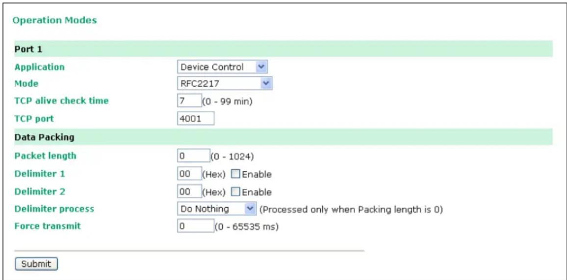
TCP alive check time (default=7 min): This field specifies how long the OnCell G3100 will wait for a response to "keep alive" packets before closing the TCP connection. The OnCell G3100 checks connection status by sending periodic "keep alive" packets. If the remote host does not respond to the packet within the time specified in this field, the OnCell G3100 will force the existing TCP connection to close. For socket and device control modes, the OnCell G3100 will listen for another TCP connection from another host after closing the connection. If TCP alive check time is set to 0, the TCP connection will remain open even if there is no response to the "keep alive" packets.
TCP port (default=4001): This is the TCP port number assignment for the serial port on the OnCell G3100. It is the port number that the serial port uses to listen to connections, and that other devices must use to contact the serial port. To avoid conflicts with well known TCP ports, the default is set to 4001.
Packet length (default=0): The Packet length setting refers to the maximum amount of data that is allowed to accumulate in the serial port buffer before sending. At the default of 0 for packet length, no maximum amount is specified and data in the buffer will be sent as specified by the delimiter settings or when the buffer is full. When a packet length between 1 and 1024 bytes is specified, data in the buffer will be sent as soon it reaches the specified length.
Delimiter 1 and Delimiter 2 (default=None): When Delimiter 1 is enabled, the serial port will clear the buffer and send the data to the Ethernet port when a specific character, entered in hex format, is received. A second delimiter character may be enabled and specified in the Delimiter 2 field, so that both characters act as the delimiter to indicate when data should be sent.

ATTENTION
In order to enable a delimiter, packet length must be set to 0. Delimiter 2 should only be enabled in conjunction with Delimiter 1 and never on its own; otherwise there may be data errors. Even when a delimiter is enabled, the OnCell G3100 will still pack and send the data when the amount of data exceeds 1 KB.
Delimiter process (default=Do Nothing): The Delimiter process field determines how the data is handled when a delimiter is received. Delimiter 1 must be enabled for this field to have effect. If Delimiters 1 and 2 are both enabled, both characters must be received for the delimiter process to take place.
- Do Nothing: Data in the buffer will be transmitted when the delimiter is received.
- Delimiter + 1: Data in the buffer will be transmitted after 1 additional byte is received following the delimiter.
- Delimiter + 2: Data in the buffer will be transmitted after 2 additional bytes are received following the delimiter.
- Strip Delimiter: Data in the buffer is first stripped of the delimiter before being transmitted.
Force transmit (default=0 ms): This parameter defines how large a gap in serial communication the OnCell G3100 will allow before packing the serial data in its internal buffer for network transmission.
As data is received through the serial port, it is stored by the OnCell G3100 in the internal buffer. The OnCell G3100 transmits data stored in the buffer via TCP/IP, but only when the internal buffer is full or as specified by the force transmit time. When set to 0, the force transmit time is disabled, and transmission is determined solely by the data in the internal buffer. At 1 to 65535, the TCP/IP protocol software will pack the serial data received after there is a gap in serial communication that exceeds the specified force transmit time.
The optimal force transmit time depends on your application, but it must be at least larger than one character interval within the specified baudrate. For example, assume that the serial port is set to 1200 bps, 8 data bits, 1 stop bit, and no parity. In this case, the total number of bits needed to send a character is 10 bits, and the time required to transfer one character is
(10 (bits) / 1200 (bits/s)) × 1000 (ms/s) = 8.3 ms.
Therefore, you should set the force transmit time to be larger than 8.3 ms, so in this case, it must be greater than or equal to 10 ms.
If it is necessary to send a series of characters in the same packet, the serial device will need to send that series of characters within the specified force transmit time, and the total length of data must be less than or equal to the OnCell G3100's internal buffer size (1 KB per port).
Socket Applications
TCP Server Mode
Operation Modes
Port 1
| Application | Socket |
| Mode | TCP Server |
| TCP alive check time | 7 (0 - 99 min) |
| Inactivity time | 0 (0 - 65535 ms) |
| Max connection | 1 |
| Ignore jammed IP | Enable Disable |
| Allow driver control | Enable Disable |
| Secure | Enable Disable |
| TCP port | 4001 |
| Cmd port | 966 |
| Connection goes down | RTS always low always highDTR always low always high |
| Data Packing | |
| Packet length | 0 (0 - 1024) |
| Delimiter 1 | 00 (Hex) Enable |
| Delimiter 2 | 00 (Hex) Enable |
| Delimiter process | Do Nothing (Processed only |
| Force transmit | 0 (0 - 65535 ms) |
TCP alive check time (default=7 min): This field specifies how long the OnCell G3100 will wait for a response to "keep alive" packets before closing the TCP connection. The OnCell G3100 checks connection status by sending periodic "keep alive" packets. If the remote host does not respond to the packet within the time specified in this field, the OnCell G3100 will force the existing TCP connection to close. For socket and device control modes, the OnCell G3100 will listen for another TCP connection from another host after closing the connection. If TCP alive check time is set to 0, the TCP connection will remain open even if there is no response to the "keep alive" packets.

ATTENTION
You should make sure the inactivity time value used here is less than the inactivity time value on the GSM/GPRS configuration page. The GSM/GPRS connection must be maintained in order to achieve the inactivity time behavior of the TCP connection.
Inactivity time (default=0 ms): This field specifies how long the OnCell G3100 will wait for incoming and outgoing data through the serial port before closing the TCP connection. The TCP connection is closed if there is no incoming or outgoing data through the serial port for the specified Inactivity time. If this field is set to 0, the TCP connection is kept active until a connection close request is received.

ATTENTION
If used, the Inactivity time setting should be greater than the Force transmit time. To prevent the unintended loss of data due to the session being disconnected, it is highly recommended that this value is set large enough so that the intended data transfer is completed.
Max connection (default=1): This field is used if you need to receive data from different hosts simultaneously. When set to 1, only a single host may open the TCP connection to the serial port. When set to 2, the specified number of hosts may open this port at the same time. When multiple hosts establish a TCP connection to the serial port at the same time, the OnCell G3100 will duplicate the serial data and transmit it to all the hosts. Cellular or Ethernet data is sent on a first-in first-out basis to the serial port when data comes into the OnCell G3100 from the Cellular or Ethernet interface.
Ignore jammed IP (default=Disable): This option determines how the port will proceed if multiple hosts are connected and one or more of the hosts stops responding as the port is transmitting data. If you select Disable, the port will wait until the data has been transmitted successfully to all hosts before transmitting the next group of data. If you select Enable, the port will ignore the host that stopped responding and continue data transmission to the other hosts.
Allow driver control (default=Disable): This option determines how the port will proceed if driver control commands are received from multiple hosts that are connected to the port. If Disable is selected, driver control commands will be ignored. If Enable is selected, control commands will be accepted, with the most recent command received taking precedence.
Secure (default=Disable): If you select Enable, data sent through the Ethernet will be encrypted with SSL.
TCP port (default=4001): This is the TCP port number assignment for the serial port on the OnCell G3100. It is the port number that the serial port uses to listen to connections, and that other devices must use to contact the serial port. To avoid conflicts with well known TCP ports, the default is set to 4001.
Command port (default=966): The Command port is the TCP port for listening to SSDK commands from the host. In order to prevent a TCP port conflict with other applications, the user can set the Command port to another port if needed.
Packet length (default=0): The Packet length setting refers to the maximum amount of data that is allowed to accumulate in the serial port buffer before sending. At the default of 0 for packet length, no maximum amount is specified and data in the buffer will be sent as specified by the delimiter settings or when the buffer is full. When a packet length between 1 and 1024 bytes is specified, data in the buffer will be sent as soon it reaches the specified length.
Delimiter 1 and Delimiter 2 (default=None): When Delimiter 1 is enabled, the serial port will clear the buffer and send the data to the Ethernet port when a specific character, entered in hex format, is received. A second delimiter character may be enabled and specified in the Delimiter 2 field, so that both characters act as the delimiter to indicate when data should be sent.

ATTENTION
In order to enable a delimiter, packet length must be set to 0. Delimiter 2 should only be enabled in conjunction with Delimiter 1 and never on its own; otherwise there may be data errors. Even when a delimiter is enabled, the OnCell G3100 will still pack and send the data when the amount of data exceeds 1 KB.
Delimiter process (default=Do Nothing): The Delimiter process field determines how the data is handled when a delimiter is received. Delimiter 1 must be enabled for this field to have effect. If Delimiters 1 and 2 are both enabled, both characters must be received for the delimiter process to take place.
- Do Nothing: Data in the buffer will be transmitted when the delimiter is received.
- Delimiter + 1: Data in the buffer will be transmitted after 1 additional byte is received following the delimiter.
- Delimiter + 2: Data in the buffer will be transmitted after 2 additional bytes are received following the delimiter.
- Strip Delimiter: Data in the buffer is first stripped of the delimiter before being transmitted.
Force transmit (default=0 ms): This parameter defines how large a gap in serial communication the OnCell G3100 will allow before packing the serial data in its internal buffer for network transmission.
As data is received through the serial port, it is stored by the OnCell G3100 in the internal buffer. The OnCell G3100 transmits data stored in the buffer via TCP/IP, but only when the internal buffer is full or as specified by the force transmit time. When set to 0, the force transmit time is disabled, and transmission is determined solely by the data in the internal buffer. At 1 to 65535, the TCP/IP protocol software will pack the serial data received after there is a gap in serial communication that exceeds the specified force transmit time.
The optimal force transmit time depends on your application, but it must be at least larger than one character interval within the specified baudrate. For example, assume that the serial port is set to 1200 bps, 8 data bits, 1 stop bit, and no parity. In this case, the total number of bits needed to send a character is 10 bits, and the time required to transfer one character is
(10 (bits) / 1200 (bits/s)) × 1000 (ms/s) = 8.3 ms.
Therefore, you should set the force transmit time to be larger than 8.3 ms, so in this case, it must be greater than or equal to 10 ms.
If it is necessary to send a series of characters in the same packet, the serial device will need to send that series of characters within the specified force transmit time, and the total length of data must be less than or equal to the OnCell G3100's internal buffer size (1 KB per port).
TCP Client Mode
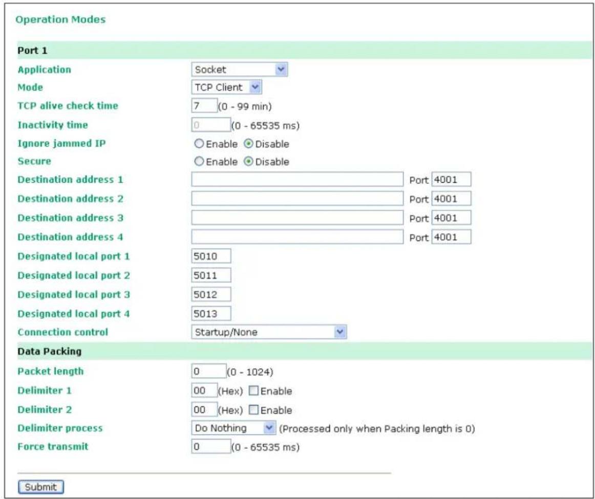
TCP alive check time (default=7 min): This field specifies how long the OnCell G3100 will wait for a response to "keep alive" packets before closing the TCP connection. The OnCell G3100 checks connection status by sending periodic "keep alive" packets. If the remote host does not respond to the packet within the time specified in this field, the OnCell G3100 will force the existing TCP connection to close. For socket and device control modes, the OnCell G3100 will listen for another TCP connection from another host after closing the connection. If TCP alive check time is set to 0, the TCP connection will remain open even if there is no response to the "keep alive" packets.

ATTENTION
You should make sure the inactivity time value used here is less than the inactivity time value on the GSM/GPRS configuration page. The GSM/GPRS connection must be maintained in order to achieve the inactivity time behavior of the TCP connection.
Inactivity time (default=0 ms): This field specifies how long the OnCell G3100 will wait for incoming and outgoing data through the serial port before closing the TCP connection. The TCP connection is closed if there is no incoming or outgoing data through the serial port for the specified Inactivity time. If this field is set to 0, the TCP connection is kept active until a connection close request is received.

ATTENTION
If used, the Inactivity time setting should be greater than the Force transmit time. To prevent the unintended loss of data due to the session being disconnected, it is highly recommended that this value is set large enough so that the intended data transfer is completed.

ATTENTION
Inactivity time is ONLY active when Connection Control (see below) is set to Any character/ Inactivity time.
Ignore jammed IP (default=Disable): This option determines how the port will proceed if multiple hosts are connected and one or more of the hosts stops responding as the port is transmitting data. If you select Disable, the port will wait until the data has been transmitted successfully to all hosts before transmitting the next group of data. If you select Enable, the port will ignore the host that stopped responding and continue data transmission to the other hosts.
Secure (default=Disable): If you select Enable, data sent through the Ethernet will be encrypted with SSL.
Destination address 1 through 4 (default=None): Specifying an IP address allows the OnCell G3100 to connect actively to the remote host. At least one destination must be provided.
TCP port (default=4001): This is the TCP port number assignment for the serial port on the OnCell G3100. It is the port number that the serial port uses to make a connection, and that serial port must use to contact the other devices. To avoid conflicts with well known TCP ports, the default is set to 4001.

ATTENTION
Up to 4 connections can be established between the OnCell G3100 and hosts. The connection speed or throughput may be low if any one of the four connections is slow, since the one slow connection will slow down the other 3 connections.

ATTENTION
The Destination IP address parameter can be the IP address, domain name, or the name defined in the host table. For some applications, the user may need to send the data actively to the remote destination domain name.
Designated local port 1 through 4 (default=5010 through 5013): Use these fields to specify the designated local ports.
Connection control (default= Startup/None): This setting determines the parameters under which a TCP connection is established or disconnected. The different options are given in the following table. In general, both the Connect condition and Disconnect conditions are given.
| Option Description | |
| Startup/None (default) | A TCP connection will be established on startup, and will remain active indefinitely. |
| Any Character/None | A TCP connection will be established when any character is received from the serial interface, and will remain active indefinitely. |
| Any Character/Inactivity Time | A TCP connection will be established when any character is received from the serial interface, and will be disconnected when Inactivity time is reached. |
| DSR On/DSR Off | A TCP connection will be established when a DSR signal of OnCell is “On”, and will remain active indefinitely. |
| DSR On/None | A TCP connection will be established when a DSR “On” signal is received, and will remain active indefinitely. |
| DCD On/DCD Off | A TCP connection will be established when a DCD signal of OnCell is “On”, and will remain active indefinitely. |
| DCD On/None | A TCP connection will be established when a DCD “On” signal is received, and will remain active indefinitely. |
Packet length (default=0): This field refers to the maximum amount of data that is allowed to accumulate in the serial port buffer before sending. At the default of 0 for packet length, no maximum amount is specified and data in the buffer will be sent as specified by the delimiter settings or when the buffer is full. When a packet length between 1 and 1024 bytes is specified, data in the buffer will be sent as soon it reaches the specified length.
Delimiter 1 and Delimiter 2 (default=None): When Delimiter 1 is enabled, the serial port will clear the buffer and send the data to the Ethernet port when a specific character, entered in hex format, is received. A second delimiter character may be enabled and specified in the Delimiter 2 field, so that both characters act as the delimiter to indicate when data should be sent.

ATTENTION
In order to enable a delimiter, packet length must be set to 0. Delimiter 2 should only be enabled in conjunction with Delimiter 1 and never on its own; otherwise there may be data errors. Even when a delimiter is enabled, the OnCell G3100 will still pack and send the data when the amount of data exceeds 1 KB.
Delimiter process (default=Do Nothing): The Delimiter process field determines how the data is handled when a delimiter is received. Delimiter 1 must be enabled for this field to have effect. If Delimiters 1 and 2 are both enabled, both characters must be received for the delimiter process to take place.
- Do Nothing: Data in the buffer will be transmitted when the delimiter is received.
- Delimiter + 1: Data in the buffer will be transmitted after 1 additional byte is received following the delimiter.
- Delimiter + 2: Data in the buffer will be transmitted after 2 additional bytes are received following the delimiter.
- Strip Delimiter: Data in the buffer is first stripped of the delimiter before being transmitted.
Force transmit (default=0 ms): This parameter defines how large a gap in serial communication the OnCell G3100 will allow before packing the serial data in its internal buffer for network transmission.
As data is received through the serial port, it is stored by the OnCell G3100 in the internal buffer. The OnCell G3100 transmits data stored in the buffer via TCP/IP, but only when the internal buffer is full or as specified by the force transmit time. When set to 0, the force transmit time is disabled, and transmission is determined solely by the data in the internal buffer. At 1 to 65535, the TCP/IP protocol software will pack the serial data received after there is a gap in serial communication that exceeds the specified force transmit time.
The optimal force transmit time depends on your application, but it must be at least larger than one character interval within the specified baudrate. For example, assume that the serial port is set to 1200 bps, 8 data bits, 1 stop bit, and no parity. In this case, the total number of bits needed to send a character is 10 bits, and the time required to transfer one character is
(10 (bits) / 1200 (bits/s)) × 1000 (ms/s) = 8.3 ms.
Therefore, you should set the force transmit time to be larger than 8.3 ms, so in this case, it must be greater than or equal to 10 ms.
If it is necessary to send a series of characters in the same packet, the serial device will need to send that series of characters within the specified force transmit time, and the total length of data must be less than or equal to the OnCell G3100's internal buffer size (1 KB per port).
UDP Mode
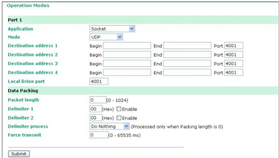
Destination address 1 through 4 (default=None): In UDP mode, you may specify up to 4 ranges of IP addresses for the serial port to connect to. At least one destination range must be provided.

ATTENTION
The maximum selectable IP address range is 64 addresses. However, when using multicast, you may enter IP addresses of the form xxx.xxx.xxx.255 in the Begin field. For example, enter 192.168.127.255 to allow the OnCell G3100 to broadcast UDP packets to all hosts with IP addresses between 192.168.127.1 and 192.168.127.254.
Local listen port (default=4001): This is the UDP port that the OnCell G3100 listens to and that other devices must use to contact the OnCell G3100. To avoid conflicts with well known UDP ports, the default is set to 4001.
Packet length (default=0): The Packet length setting refers to the maximum amount of data that is allowed to accumulate in the serial port buffer before sending. At the default of 0 for packet length, no maximum amount is specified and data in the buffer will be sent as specified by the delimiter settings or when the buffer is full. When a packet length between 1 and 1024 bytes is specified, data in the buffer will be sent as soon it reaches the specified length.
Delimiter 1 and Delimiter 2 (default=None): When Delimiter 1 is enabled, the serial port will clear the buffer and send the data to the Ethernet port when a specific character, entered in hex format, is received. A second delimiter character may be enabled and specified in the Delimiter 2 field, so that both characters act as the delimiter to indicate when data should be sent.

ATTENTION
In order to enable a delimiter, packet length must be set to 0. Delimiter 2 should only be enabled in conjunction with Delimiter 1 and never on its own; otherwise there may be data errors. Even when a delimiter is enabled, the OnCell G3100 will still pack and send the data when the amount of data exceeds 1 KB.
Delimiter process (default=Do Nothing): The Delimiter process field determines how the data is handled when a delimiter is received. Delimiter 1 must be enabled for this field to have effect. If Delimiters 1 and 2 are both enabled, both characters must be received for the delimiter process to take place.
- Do Nothing: Data in the buffer will be transmitted when the delimiter is received.
- Delimiter + 1: Data in the buffer will be transmitted after 1 additional byte is received following the delimiter.
- Delimiter + 2: Data in the buffer will be transmitted after 2 additional bytes are received following the delimiter.
- Strip Delimiter: Data in the buffer is first stripped of the delimiter before being transmitted.
Force transmit (default=0 ms): This parameter defines how large a gap in serial communication the OnCell G3100 will allow before packing the serial data in its internal buffer for network transmission.
As data is received through the serial port, it is stored by the OnCell G3100 in the internal buffer. The OnCell G3100 transmits data stored in the buffer via TCP/IP, but only when the internal buffer is full or as specified by the force transmit time. When set to 0, the force transmit time is disabled, and transmission is determined solely by the data in the internal buffer. At 1 to 65535, the TCP/IP protocol software will pack the serial data received after there is a gap in serial communication that exceeds the specified force transmit time.
The optimal force transmit time depends on your application, but it must be at least larger than one character interval within the specified baudrate. For example, assume that the serial port is set to 1200 bps, 8 data bits, 1 stop bit, and no parity. In this case, the total number of bits needed to send a character is 10 bits, and the time required to transfer one character is
(10 (bits) / 1200 (bits/s)) × 1000 (ms/s) = 8.3 ms.
Therefore, you should set the force transmit time to be larger than 8.3 ms, so in this case, it must be greater than or equal to 10 ms.
If it is necessary to send a series of characters in the same packet, the serial device will need to send that series of characters within the specified force transmit time, and the total length of data must be less than or equal to the OnCell G3100's internal buffer size (1 KB per port).
Ethernet Modem Mode
Operation Modes
Port 1
Application
TCP alive check time
TCP port
Ethernet Modem
7 (0 - 99 min)
4001
Please note that in Ethernet Modem mode, DTR, RTS, and DCD signals are disabled for ports that are using RS-422 or RS-485.
Submit
The OnCell G3100 accepts the AT command ATD IP address: TCP port (for example, ATD
192.168.127.1:4001) from the serial port and then requests a TCP connection from the remote Ethernet Modem or PC. Here IP address is the IP address of the remote Ethernet modem or PC, and TCP port is the TCP port number of the remote Ethernet modem or PC. Once the remote unit accepts this TCP connection, the OnCell G3100 will send out the "CONNECT baud" signal via the serial port and then enter data mode.
TCP alive check time (default=7 min): This field specifies how long the OnCell G3100 will wait for a response to "keep alive" packets before closing the TCP connection. The OnCell G3100 checks connection status by sending periodic "keep alive" packets. If the remote host does not respond to the packet within the time specified in this field, the OnCell G3100 will force the existing TCP connection to close. For socket and device control modes, the OnCell G3100 will listen for another TCP connection from another host after closing the connection. If TCP alive check time is set to 0, the TCP connection will remain open even if there is no response to the "keep alive" packets.
TCP port (default=4001): This is the TCP port number assignment for the serial port on the OnCell G3100. It is the port number that the serial port uses to listen to connections, and that other devices must use to contact the serial port. To avoid conflicts with well known TCP ports, the default is set to 4001.
Dial-in
The OnCell G3100 listens for a TCP/IP connection request from the remote Ethernet modem or host. The OnCell G3100's response depends on the ATS0 value, as follows.
ATS0 = 0 :
The OnCell G3100 will temporarily accept the TCP connection and then send the RING signal out through the serial port. The serial controller must reply with ATA within 2.5 seconds to accept the connection request, after which the OnCell G3100 enters data mode. If no ATA command is received, the OnCell G3100 will disconnect after sending three RING signals.
ATS0 ≥1 :
The OnCell G3100 will accept the TCP connection immediately and then send the "CONNECT baud" command to the serial port, in which baud represents the baudrate of the OnCell G3100's serial port. After that, the OnCell G3100 immediately enters data mode.
Dial-out
The OnCell G3100 accepts the AT command "ATD IP: TCP port" from the serial port and then requests a TCP connection from the remote Ethernet Modem or PC. Here IP is the IP address of the remote Ethernet modem or PC, and TCP port is the TCP port number of the remote Ethernet modem or PC. Once the remote unit accepts this TCP connection, the OnCell G3100 will send out the CONNECT baud" signal via the serial port and then enter data mode.
Disconnection request from local site
When the OnCell G3100 is in data mode, the user can initiate disconnection by sending “+++” from the local serial port to the OnCell G3100. Some applications allow you to set the DTR signal to off, which will also initiate disconnection. The OnCell G3100 will enter command mode, and after 1 second, you can then enter ATH to shut down the TCP connection. The OnCell G3100 will return a NO CARRIER via the serial port.
NOTE
The “++” command cannot be divided. The “+” character can be changed in register S2, and the guard time, which prefixes and suffixes the “+++” in order to protect the raw data, can be changed in register S12.
Disconnection request from remote site
After the TCP connection has been shut down by the remote Ethernet modem or PC, the OnCell G3100 will send the NO CARRIER signal via the serial port and then return to command mode.
AT Commands
The OnCell G3100 supports the following common AT commands as used with a typical modem:
| No. | AT command | Description | Remarks |
| 1 ATA | Answer manually | ||
| 2 | ATD: | Dial up the IP address : Port No. | |
| 3 ATE | ATE0= Echo OFF | ATE1= Echo ON (default) | |
| 4 ATH | ATH0= On-hook (default) | ATH1= Off-hook | |
| 5 | ATI, ATI0, ATI1, ATI2 | Modem version | reply “OK” only |
| 6 | ATL | Speaker volume option | reply “OK” only |
| 7 | ATM | Speaker control option | reply “OK” only |
| 8 ATO | On line command | ||
| 9 | ATP, ATT | Set Pulse/ Tone Dialing mode | reply “OK” only |
| 10 | ATQ0, ATQ1 | Quiet command (default= ATQ0) | |
| 11 | ATSr=n | Change the contents of S register | See “S registers” |
| 12 | ATSr? | Read the contents of S register | See “S registers” |
| 13 | ATV Result code type | ATV0 for digit code,ATV1 for text code (default)0= OK1= connect2= ring3= No carrier4= error | |
| 14 | ATZ | Reset (disconnect, enter command mode and restore the flash settings) | |
| 15 | AT&C | Serial port DCD controlAT&C0= DCD always onAT&C1= DTE detects connection by DCD on/off (default) | |
| 16 | AT&F | Restore manufacturer's settings | |
| 17 | AT&G | Select guard time | reply “OK” only |
| 18 | AT&R | Serial port RTS option command | reply “OK” only |
| 19 | AT&S | Serial port DSR control | reply “OK” only |
| 20 | AT&V | View settings | |
| 21 | AT&W | Write current settings to flash for next boot up | |
S Registers
| No. | S Register | Description & default value | Remarks |
| 1 | S0 | Ring to auto-answer (default=0) | |
| 2 | S1 | Ring counter (always=0) | no action applied |
| 3 S2 | Escape code character (default=43 ASCII “+”) | ||
| 4 S3 | Return character (default=13 ASCII) | ||
| 5 S4 | Line feed character (default=10 ASCII) | ||
| 6 S5 | Backspace character (default=8 ASCII) | ||
| 7 | S6 | Wait time for dial tone (always=2, unit=sec) | no action applied |
| 8 | S7 | Wait time for carrier (default=3, unit=sec) | |
| 9 | S8 | Pause time for dial delay (always=2, unit=sec) | no action applied |
| 10 | S9 | Carrier detect response time (always=6, unit 1/10 sec) | no action applied |
| 11 | S10 | Delay for hang up after carrier (always=14, unit 1/10 sec) | no action applied |
| 12 | S11 | DTMF duration and spacing (always=100 ms) | no action applied |
| 13 | S12 | Escape code guard time (default=50, unit 1/50 sec) to control the idle time for “+++” | |
SMS Tunnel Mode
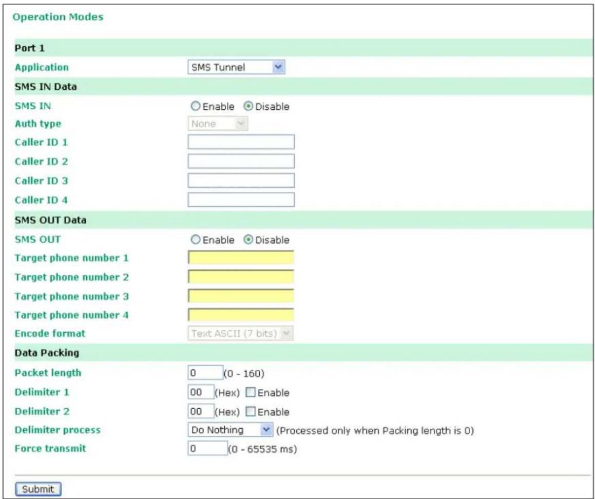
SMS IN enable (default=Disable): To allow forwarding incoming short message to the OnCell G3100's serial port as data.
Auth type (default=none): To allow Caller ID Authentication
Caller ID (1 through 4): Phone number should be specified.
SMS OUT enable (default=Disable): To allow data received from the attached serial devices to be transmitted as short messages.
Target Phone Number (1 through 4): Phone number should be specified.
Encode Format
| SMS Data Format | |
| Text ASCII (7 bits) (default) | 7-bit text format (160 bytes per packet) |
| Binary | 8-bit binary (140 bytes per packet) |
| Unicode | 16-bit Unicode (UCS2) format (70 bytes per packet) |

ATTENTION
The Target Phone Number must be specified if SMS-OUT is activated.
The Target Phone Number and Caller ID can be written in either international format, starting with “+” followed by the country code, or local format, starting with local area code.
If you don't use Caller ID authentication, the OnCell G3100 will allow all incoming short messages as serial data to be forwarded to its serial port. This includes system broadcasts and advertisements.
Packet length (default=0): The Packet length setting refers to the maximum amount of data that is allowed to accumulate in the serial port buffer before sending. At the default of 0 for packet length, no maximum amount is specified and data in the buffer will be sent as specified by the delimiter settings or when the buffer is full. When a packet length between 1 and 160 bytes is specified, data in the buffer will be sent as soon it reaches the specified length.
Delimiter 1 and Delimiter 2 (default= None): When Delimiter 1 is enabled, the serial port will queue the data in the buffer and send the data to the Cellular or Ethernet port when a specific character, entered in hex format, is received. A second delimiter character may be enabled and specified in the Delimiter 2 field, so that both characters act as the delimiter to control when data should be sent.

ATTENTION
In order to enable a delimiter, packet length must be set to 0. Delimiter 2 should only be enabled in conjunction with Delimiter 1 and never on its own; otherwise there may be data errors. Even when a delimiter is enabled, the OnCell G3100 will still pack and send the data when the amount of data exceeds 1 KB.
Delimiter process (default= Do Nothing): The Delimiter process field determines how the data is handled when a delimiter is received. Delimiter 1 must be enabled for this field to have effect. If Delimiters 1 and 2 are both enabled, both characters must be received for the delimiter process to take place.
- Do Nothing: Data in the buffer will be transmitted when the delimiter is received.
- Delimiter + 1: Data in the buffer will be transmitted after 1 additional byte is received following the delimiter.
- Delimiter + 2: Data in the buffer will be transmitted after 2 additional bytes are received following the delimiter.
- Strip Delimiter: Data in the buffer is first stripped of the delimiter before being transmitted.
Force transmit (default=0 ms): This parameter defines how large a gap in serial communication the OnCell G3100 will allow before packing the serial data in its internal buffer for network transmission.
As data is received through the serial port, it is stored by the OnCell G3100 in the internal buffer. The OnCell G3100 transmits data stored in the buffer via SMS, but only when the internal buffer is full or as specified by the force transmit time. When set to 0, the force transmit time is disabled, and transmission is determined solely by the data in the internal buffer. At 1 to 65535, the SMS protocol software will pack the serial data received after there is a gap in serial communication that exceeds the specified force transmit time.
The optimal force transmit time depends on your application, but it must be at least larger than one character interval within the specified baudrate. For example, assume that the serial port is set to 1200 bps, 8 data bits, 1 stop bit, and no parity. In this case, the total number of bits needed to send a character is 10 bits, and the time required to transfer one character is
(10 (bits) / 1200 (bits/ s)) × 1000 (ms/ s) = 8.3 ms.
Therefore, you should set the force transmit time to be larger than 8.3 ms, so in this case, it must be greater than or equal to 10 ms.
If it is necessary to send a series of characters in the same packet, the serial device will need to send that series of characters within the specified force transmit time, and the total length of data must be less than or equal to the OnCell G3100's internal buffer size.
Disabled Mode

When the Application is set to Disable, the relevant port will be disabled.
Configuring the Cellular-Enabling Ethernet Device
In this chapter, we explain how to configure the Cellular-enabling Ethernet device.
The following topics are covered in this chapter:
□ Host to OnCell via Cellular
☐ OnCell to Host via Cellular
Host to OnCell via Cellular
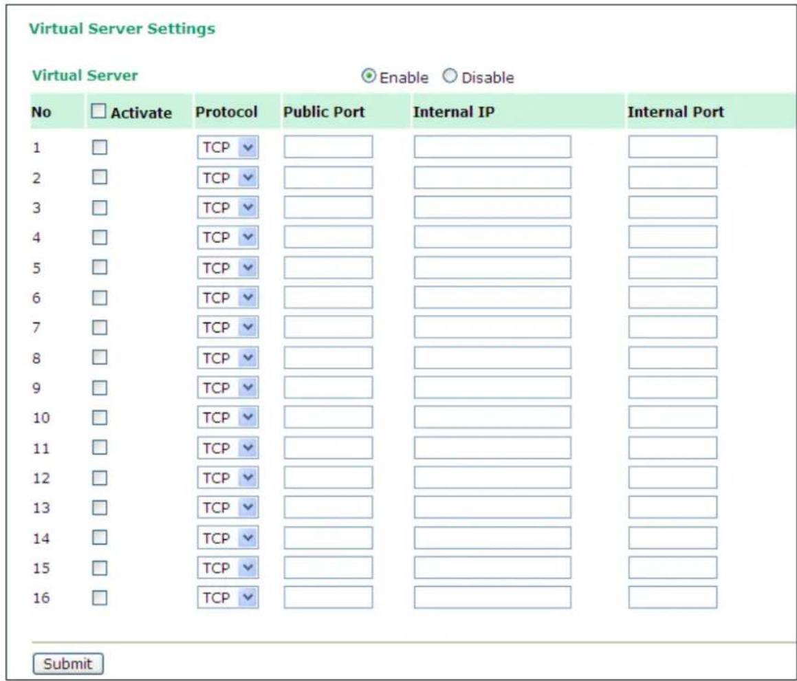
Go to System Management → Misc. Network Settings → Virtual Server Settings (default=Disable): This function allows remote users to access the Host or FTP services via a public IP address, and automatically redirects them to local servers in the LAN (Local Area Network).
The OnCell firewall feature filters out unrecognized packets to protect your LAN network when computers networked with the OnCell are hidden from public view. If you wish, you can make some of the LAN computers accessible from the Internet by enabling Virtual Server. Depending on the requested service, the OnCell redirects the external service request to the appropriate server within the LAN network.
The OnCell is also capable of port-redirection meaning incoming traffic to a particular port may be redirected to a different port on the server computer.
Public Port: The public port is the port seen from the Internet side. Public ports cannot be set to ports used by OP modes (950, 966, 4001, ...)
Internal IP: Enter the IP address of the host on your local network that you want to link the incoming service to.
Internal Port: The internal port is the port being used by the application on the host within your local network.
OnCell to Host via Cellular
This section explains the configuration for when the Ethernet device acts as the Client. In order for the Ethernet device to send data to the host, it must set the OnCell as a gateway. This function will automatically detect the OnCell's IP address by DHCP enable (default=enable) Please refer page 58 for DHCP function explanation. Alternatively, you can manually enter the Internet Protocol (TCP/IP) properties, and DNS server addresses in the Ethernet device.
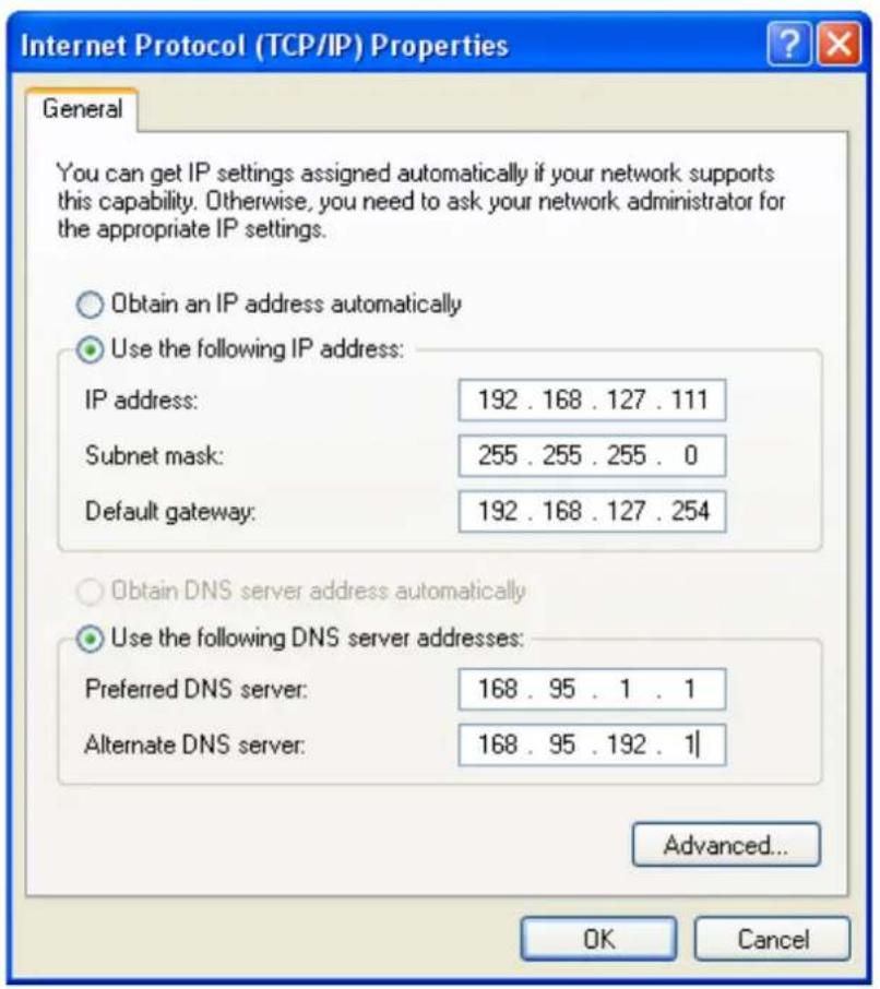
In this chapter, we explain how to configure Virtual Modem Mode for running AT command operating system devices. This operation mode is available for CSD, SMS and GPRS cellular services. Before starting configuration, you will need to select the appropriate cellular service because different cellular services have different software installation methods.
Note: This function is only supported by the OnCell G3100 Rev. 2.0 and Rev. 3.0. Please refer to the Specifications section of Chapter 1 (page 1-3) for more information.
The following topics are covered in this chapter:
☐ OnCell G3100 Web Settings
Installing Windows Driver Manager
➢ Using Windows Driver Manager
➢ Using PComm for Data Transmission
□ CSD via AT command
☐ SMS via AT command
□ GPRS via AT command
☐ GPRS via Windows Dial-up Network
OnCell G3100 Web Settings
From the left navigation panel, click Network Settings → GSM GPRS Settings to enable Virtual Modem Settings. The configuration items are described below:
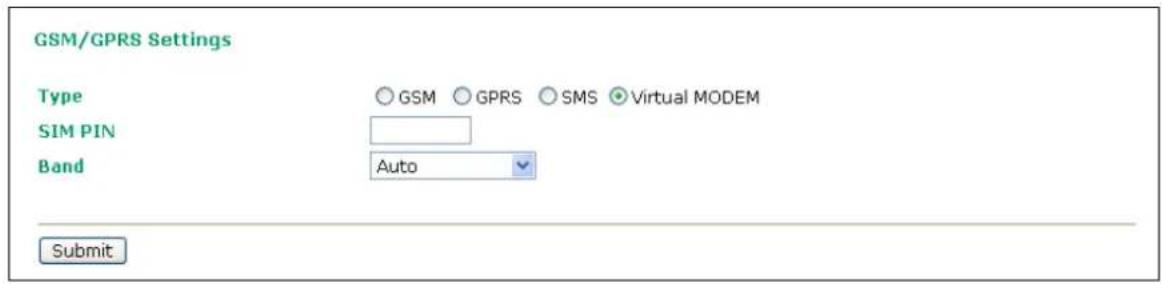
Installing Windows Driver Manager
Windows Driver Manager should be installed for all cellular connections.
- Download Windows Driver Manager from www.moxa.com, and then click the INSTALL COM Driver button to install the Windows Driver. Once the installation program starts running, click Yes to proceed.
- Click Next when the Welcome screen opens to proceed with the installation.
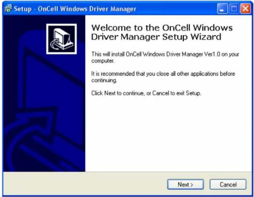
- Click Next to install program files to the default directory, or click Browse to select an alternate location.
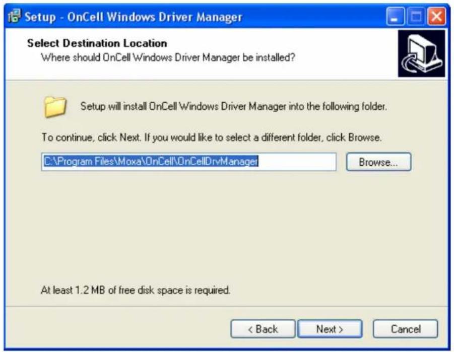
- The Setup window will display a summary of the installation options. Click Install to begin the installation.
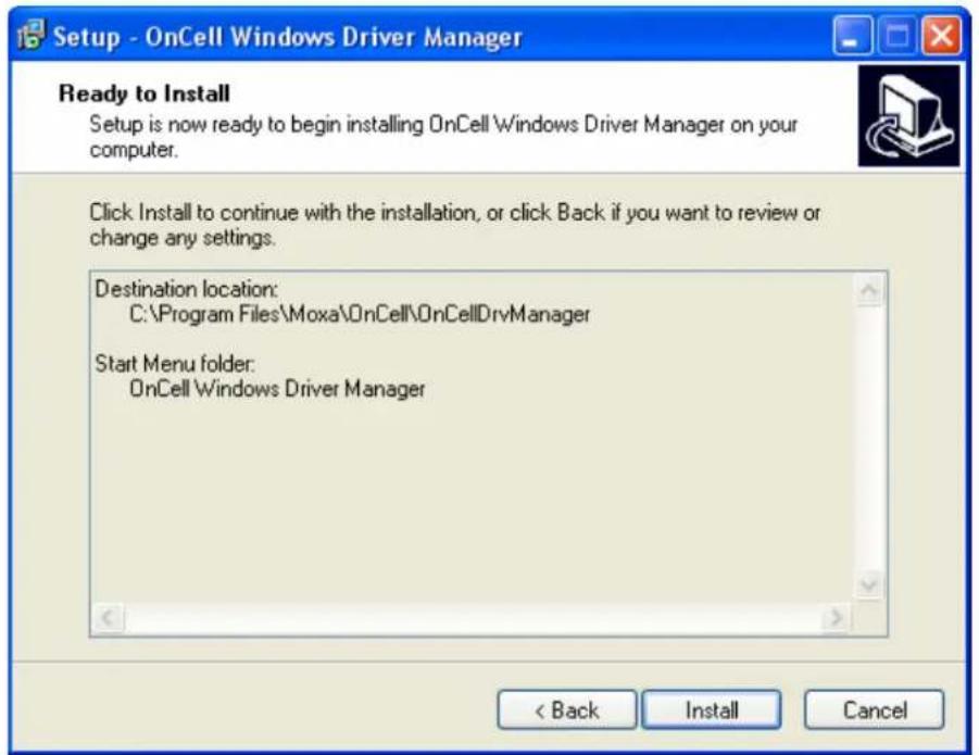
- The setup window will report the progress of the installation. To change the installation settings, click Back and navigate to the previous screen. On Windows XP, the installer will display a message that the software has not passed Windows Logo testing, as shown below. Click Continue Anyway to finish the installation.
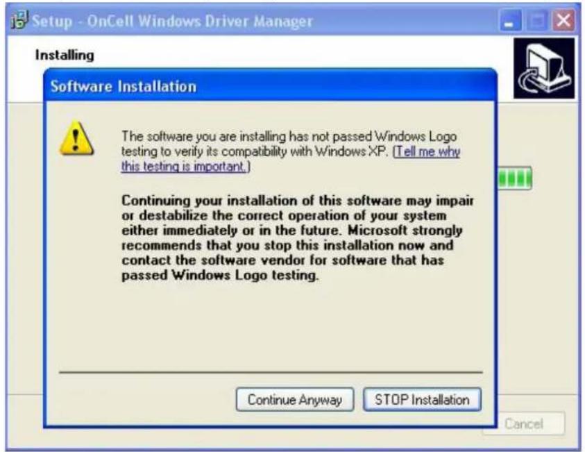
- Click Finish to complete the installation of the Windows Driver Manager.
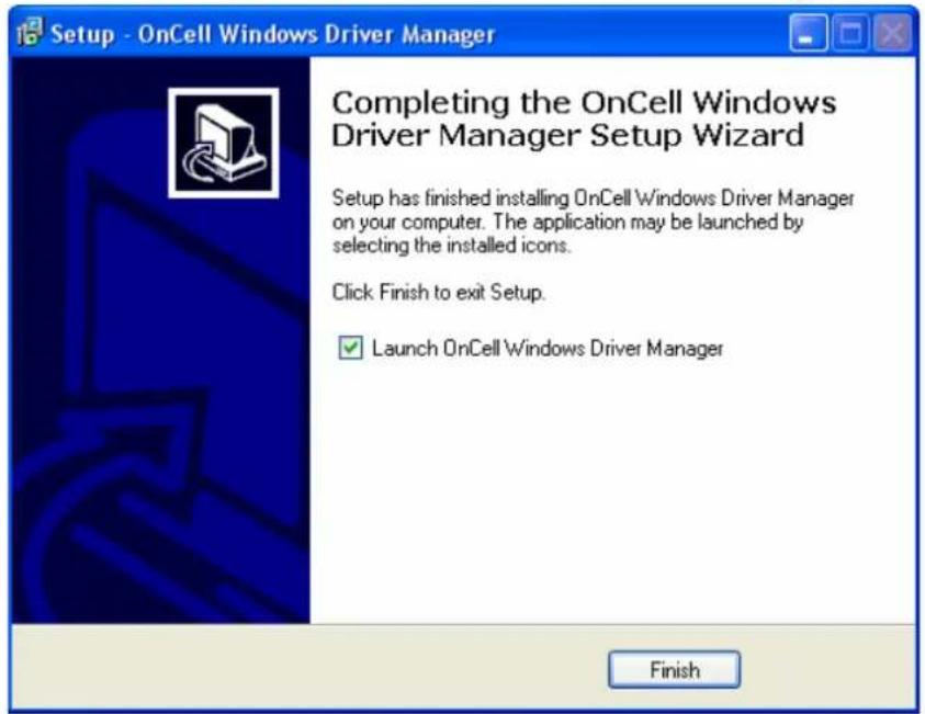
Using Windows Driver Manager
After you install Windows Driver Manager, you can set up the OnCell G3100's serial ports as remote COM ports for your PC host. Make sure that the serial port(s) on your OnCell G3100 are set to Real COM mode when mapping COM ports with Windows Driver Manager.
- Go to Start → Windows Driver Manager → Windows Driver Manager to start the COM mapping utility. Click the Add icon.
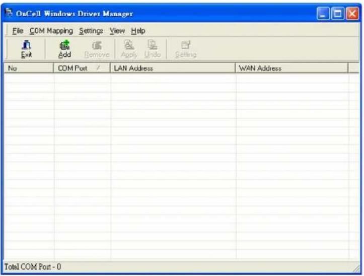
- Click Rescan to search for OnCell IP gateways. From the list that is generated, select the server that you will map COM ports to, and then click OK.
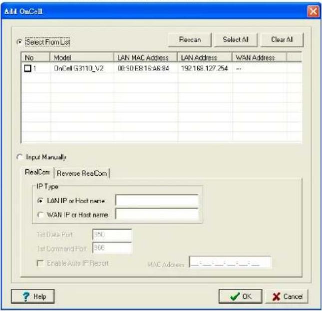
- COM ports and their mappings will appear in blue until they are activated. Activating the COM ports saves the information in the host system registry and makes the COM port available for use. The host computer will not have the ability to use the COM port until the COM ports are activated. Click Yes to activate the COM ports at this time, or click No to activate the COM ports later.
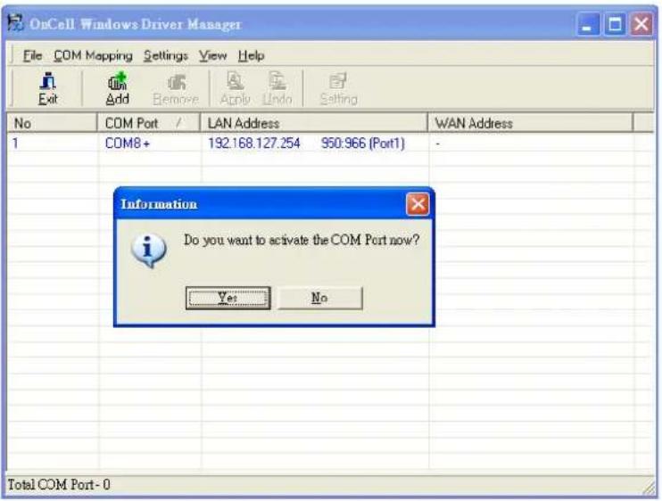
Using PComm for Data Transmission
The following instructions and screenshots show how to data transmit using PComm Terminal Emulator, which is available free of charge as part of the PComm Lite suite. You may use a different terminal emulator utility, although your actual screens and procedures may vary slightly from the following instructions.
- From the Windows desktop select Start → All Programs → PComm Lite → Terminal Emulator.
- The PComm Terminal Emulator window should appear. From the Port Manager menu, select Open, or simply click the Open icon as shown below:
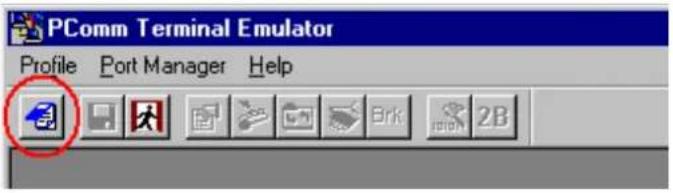
- The Property window opens automatically. Select the Communication Parameter tab, and then select the appropriate COM port for the connection (COM8 in this example). Configure the parameters for 115200, 8, N, 1 (115200 for Baudrate, 8 for Data Bits, None for Parity, and 1 for Stop Bits).
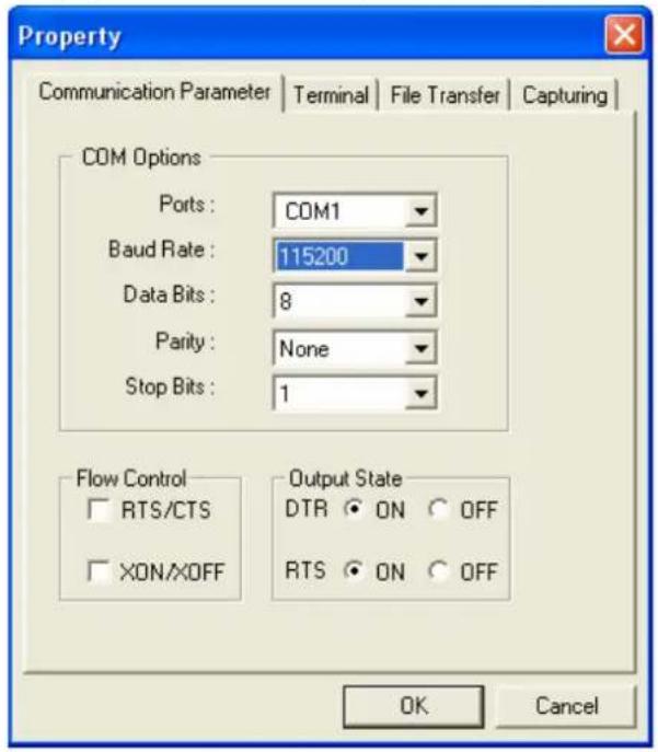
CSD via AT command
Caller dialing out
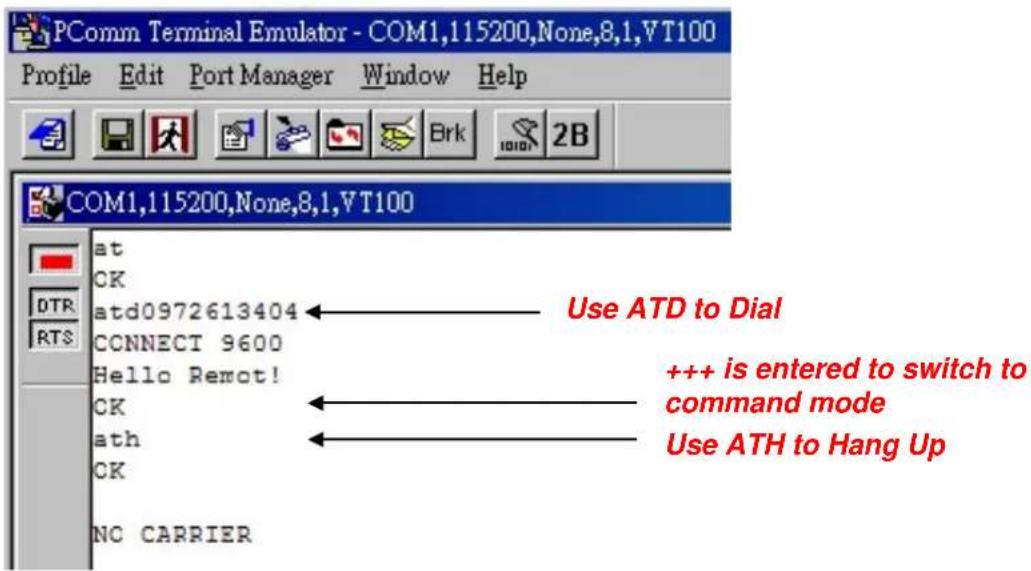
Receiver answering a dial-in
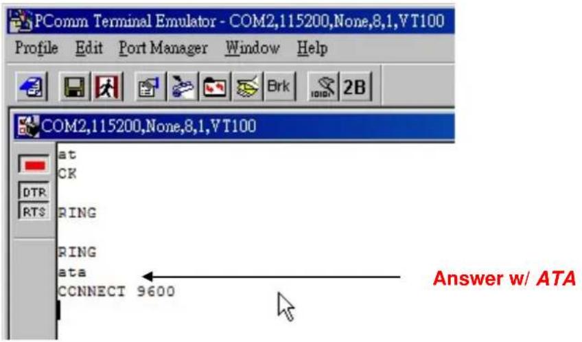
SMS via AT command
Illustrating of uUser sending a message
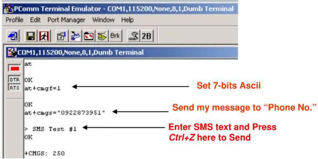
Receiver getting a message
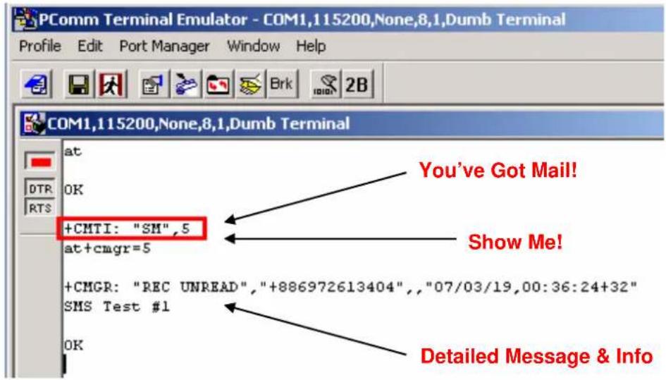
GPRS via AT command
You can connect to the Internet (GPRS) via AT command. There are two commands you need to know:
APN: AT+CGDCONT=1, "IP", "
Dial: ATD*99****1#
GPRS via Windows Dial-up Network
- Go to Start → Settings → Control Panel → Phone and Modem Options.
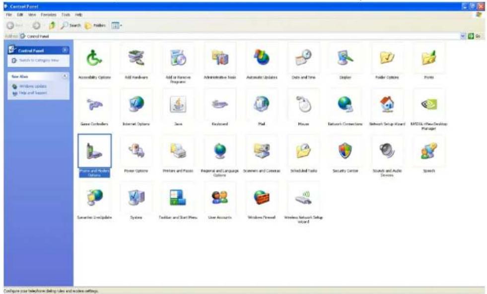
- Click on Add button.
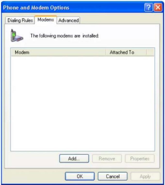
- Checkmark the box for Don't detect my modem; I will select it from a list. Click Next to continue.
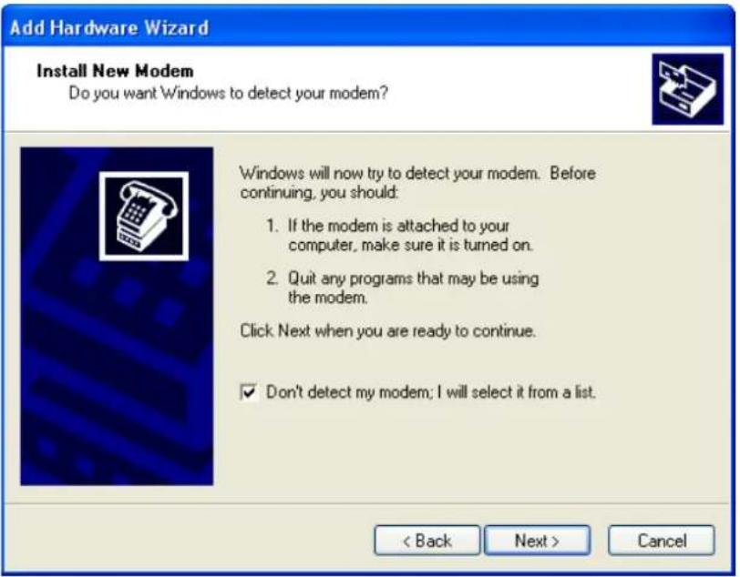
- When the Add Hardware Wizard page appears, select Have Disk.
![Add Hardware Wizard Install New Modem Select the manufacturer and model of your modem. If your modem is not listed, or if you have an installation disk, click Have Disk. Manufacturer [Standard Modem Types] Models Communications cable between two computers Parallel cable between two computers Standard 300 bps Modem Standard 1200 bps Modem This driver is digitally signed. Tell me why driver signing is important Have Disk... < Back Next > Cancel](/content/2026/06/1160625/images/90dcb1bab237fd199419904089c92a63d6ca57d9ba7f3fb4b4555423b06871bb.jpg)
- Browse the Windows Driver Manager folder and select the vmodem_v1.0.2.inf file. Click OK to continue.
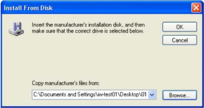
- The OnCell G3100 Modem (GPRS) model has been added to the list. Select it and then click Next.
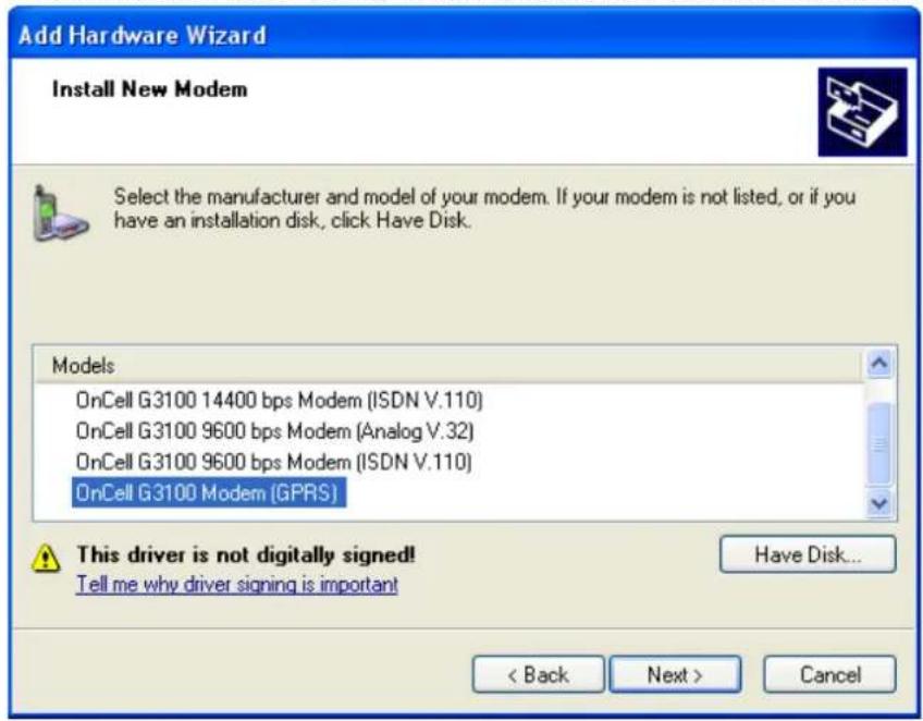
- Click on Selected ports. This COM port needs to be the COM port number mapped by Windows Driver Manager (not necessarily COM 1). Choose the COM port created by Windows Driver Manager to proceed, click Next to continue.
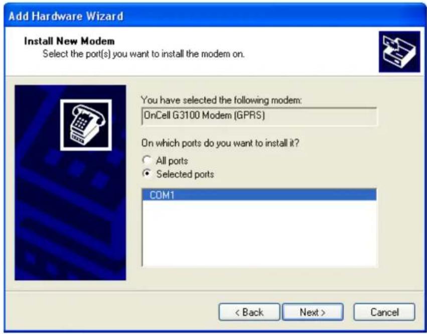
- A setup window will pop up for hardware installation. To change the installation settings, click Back and navigate to the previous screen. In Windows XP, Setup will display the following message indicating that the software has not passed Windows Logo testing. Click Continue Anyway to finish the installation.
![Add Hardware Wizard Install New Modem Windows is installing the modem(s) Hardware Installation The software you are installing for this hardware: OnCell G3100 Modem (GPRS) has not passed Windows Logo testing to verify its compatibility with Windows XP. [Tell me why this testing is important.] Continuing your installation of this software may impair or destabilize the correct operation of your system either immediately or in the future. Microsoft strongly recommends that you stop this installation now and contact the hardware vendor for software that has passed Windows Logo testing. Continue Anyway STOP Installation](/content/2026/06/1160625/images/d2fa04e9709e0164863ca83eb2d90fa269f4d8dc8c40883d302f4403e83cb545.jpg)
- Click Finish to complete the installation of the new modem.
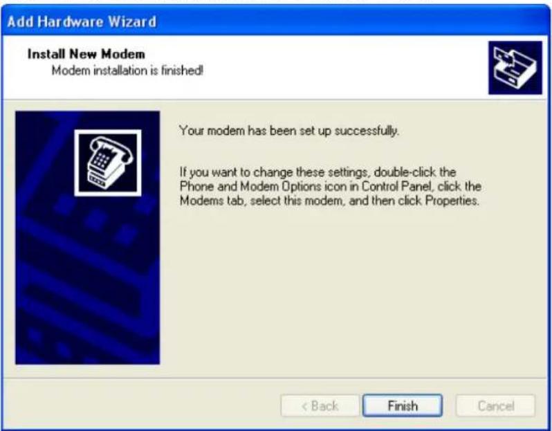
- The Phone and Modem Options page will show up. Select and double click on the modem attached to the COM port (not necessarily COM 1) mapped by Window Driver Manager.
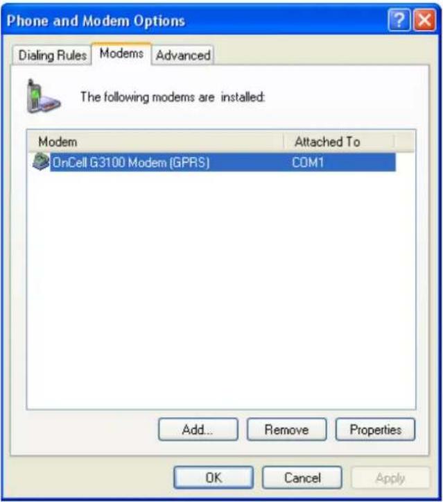
- Click on the Advanced tab. Under Extra initialization commands, enter AT+CGDCONT=1, "IP", "INTERNET" and click OK to continue.
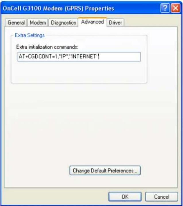
- Click OK to close the page. The COM port number will be whichever one was mapped by Windows Driver Manager.
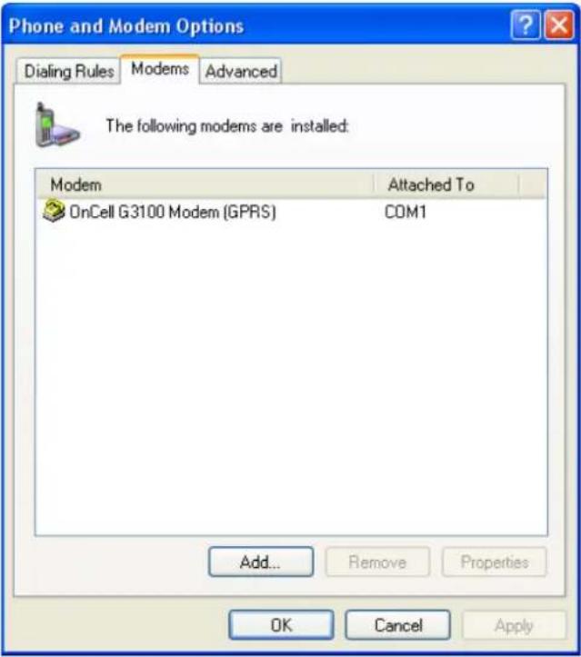
- Go to Start → Settings → Network Connections → Create a new connection.
14. Click on Next.
15. Select Connect to the Internet, and then click Next.
- Select Set up my connection manually, and then click Next.
- Create your own ISP name.
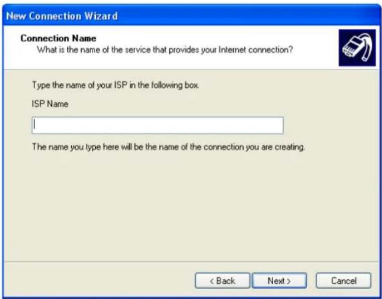
- You must enter *99***1# as a phone number, and click Next.
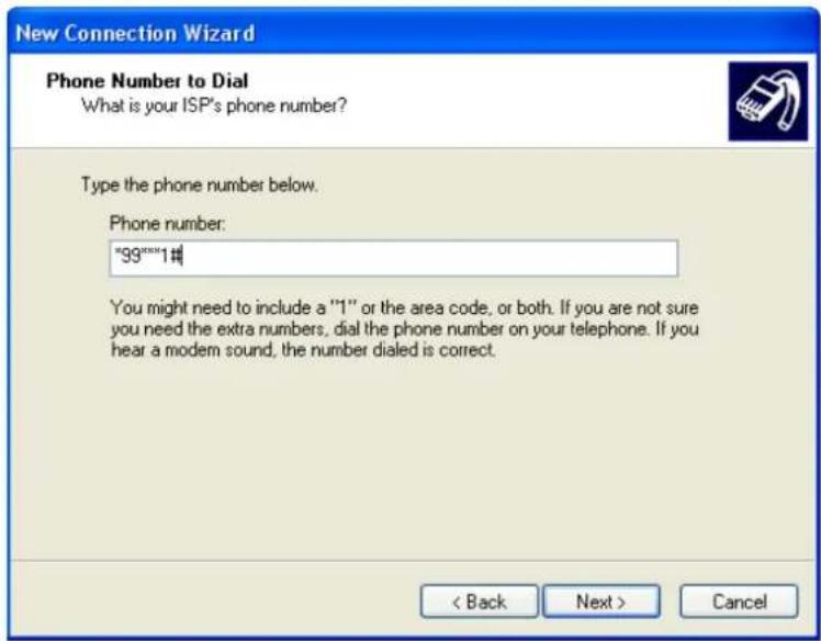
- Type the Internet Account Information. The information must match ISP Settings. Click Next to continue.
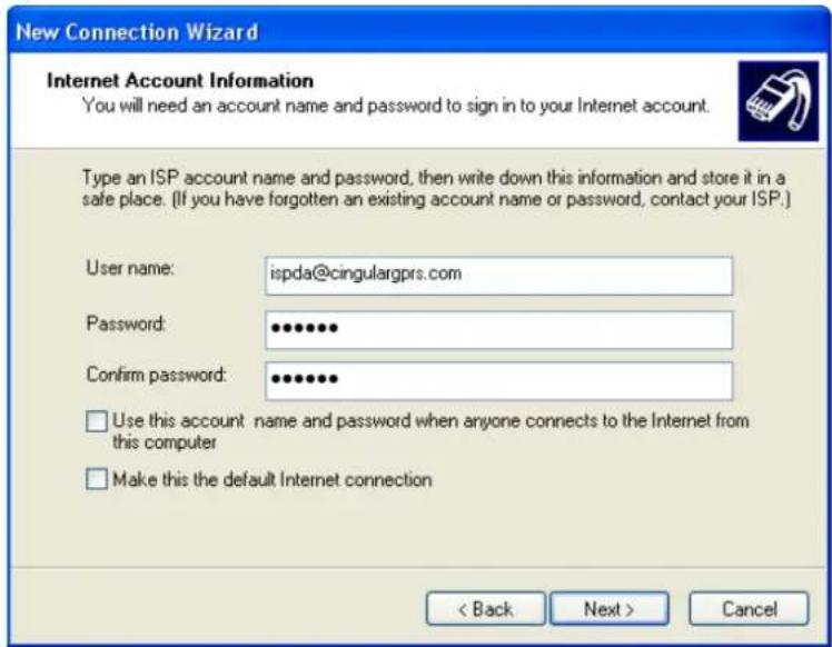
- Click Finish to complete the new connection.
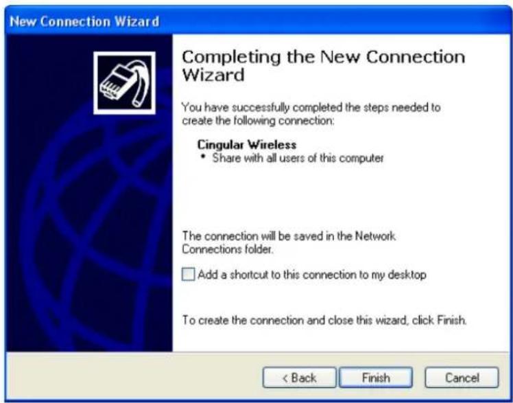
- Click Dial to connect to a cellular network.
![Connect Cingular Wireless User name: ispda@cingularqprs.com Password: [To change the saved password, click here] ✓ Save this user name and password for the following users: ○ Me only ○ Anyone who uses this computer Dial: "99"***1# Dial Cancel Properties Help](/content/2026/06/1160625/images/ce51e26fb9c7a038111d7da50a2defc464496e484a4bb071536ef2d180f3f28f.jpg)
In this chapter, we explain how to configure a VPN with the OnCell 5000 web console.
The following topics are covered in this chapter:
□ What Are VPNs?
□ OnCell VPN Specifications
☐ OnCell VPN Web Console Settings
□ Manual Key/ ESP
Configuration
Remote Network
Local Network
- Incoming Security Settings
➢ Outgoing Security Settings
□ ISAKMP/PSK
Configuration
Remote Network
➢ ISAKMP (Key Management)
Local Identity
ISAKMP phase 1
ISAKMP phase 2
▶ Advanced settings
☐ VPN system log events and error codes
What Are VPNs?
Computers that are part of a VPN use a second, "virtual" IP address to connect to the Internet. Instead of running across a single private network, some of the links between nodes that are part of a VPN use open network connections or virtual circuits on a larger network, such as the Internet. With the help of VPNs, cellular devices acting as a VPN client can initiate a connection with a VPN server. Once the connection is established, cellular devices can communicate with other network devices on the same private network.
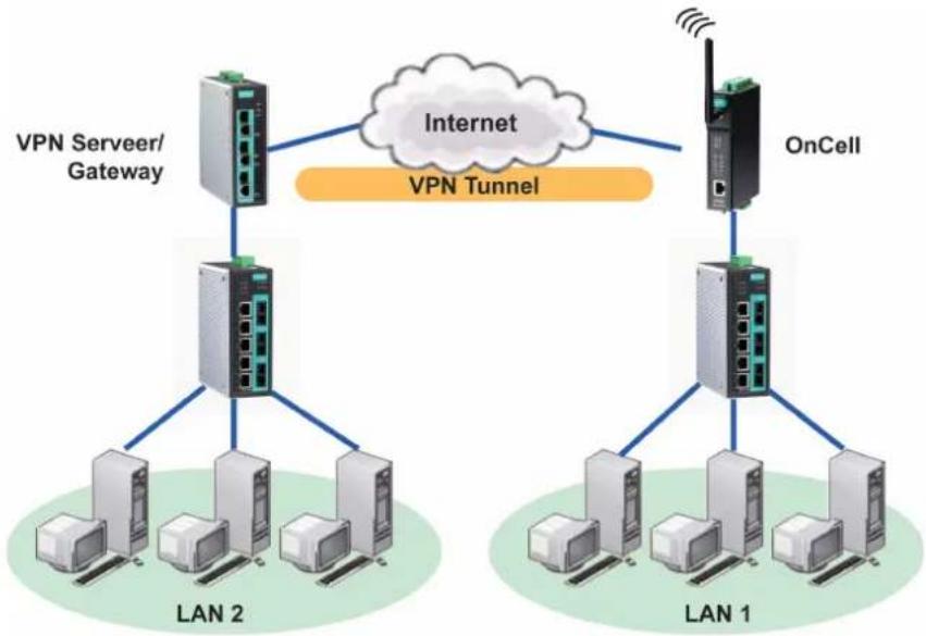
flowchart
graph TD
    subgraph LAN 1
        A["OnCell"] --> B["Internet"]
        B --> C["OnCell"]
        D["LAN 1"] --> E["LAN 2"]
        F["LAN 2"] --> G["Internet"]
        H["LAN 2"] --> I["Internet"]
        J["LAN 2"] --> K["Internet"]
        L["LAN 1"] --> M["OnCell"]
        N["Internet"] --> O["OnCell"]
    end
    subgraph LAN 2
        P["LAN 2"] --> Q["Internet"]
        R["LAN 2"] --> S["Internet"]
        T["LAN 2"] --> U["Internet"]
        V["LAN 2"] --> W["Internet"]
        X["LAN 2"] --> Y["Internet"]
        Z["LAN 2"] --> AA["Internet"]
        AB["Internet"] --> AC["Internet"]
    end
    subgraph LAN 1
        AD["OnCell"] --> AE["Internet"]
        AF["OnCell"] --> AG["Internet"]
        AH["OnCell"] --> AI["Internet"]
        AJ["OnCell"] --> AK["Internet"]
        AL["OnCell"] --> AM["Internet"]
        AN["OnCell"] --> AO["Internet"]
    end
    subgraph LAN 2
        AP["OnCell"] --> AQ["Internet"]
        AR["OnCell"] --> AS["Internet"]
        AT["OnCell"] --> AU["Internet"]
        AV["OnCell"] --> AW["Internet"]
        AX["OnCell"] --> AY["Internet"]
        AZ["OnCell"] --> BA["Internet"]
    end
    subgraph LAN 1
        BB["OnCell"] --> BC["Internet"]
        BD["OnCell"] --> BE["Internet"]
        BF["OnCell"] --> BG["Internet"]
        BH["OnCell"] --> BI["Internet"]
        BJ["OnCell"] --> BK["Internet"]
    end
    subgraph LAN 2
        BL["OnCell"] --> BM["Internet"]
        BN["OnCell"] --> BO["Internet"]
        BP["OnCell"] --> BQ["Internet"]
        BR["OnCell"] --> BS["Internet"]
    end
    subgraph LAN 1
        BT["OnCell"] --> BU["Internet"]
        BV["OnCell"] --> BW["Internet"]
        BX["OnCell"] --> BY["BHQ"]
    end
    subgraph LAN 2
        BZ["OnCell"] --> CA["Internet"]
        CB["OnCell"] --> CD["Internet"]
        CE["OnCell"] --> CF["Internet"]
    end
OnCell VPN Specifications
- OnCell IPSec provides security in one scenario with Gateway-to-gateway topology
- OnCell initiates VPN connection to VPN Server
- OnCell IPSec operates in Tunnel mode with IPsec VPN tunnel
➢ Manual Key/ESP, IKE/PSK
DES/3DES/AES128/AES192/AES256 encryption
MD5/SHA1 authentication
• IPsec NAT traversal, Anti-Replay, and PFS (Perfect Forwarding Secrecy).
Example: Gateway to gateway connection between OnCell and IPSec server
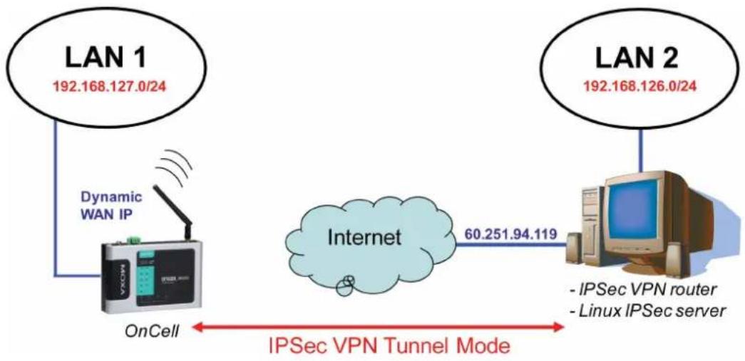
flowchart
graph LR
    A["LAN 1<br>192.168.127.0/24"] --> B["OnCell"]
    C["LAN 2<br>192.168.126.0/24"] --> D["Internet<br>60.251.94.119"]
    B --> E["IPSec VPN Tunnel Mode"]
    D --> F["- IPSec VPN router<br>- Linux IPSec server"]
    style A fill:#f9f,stroke:#333
    style C fill:#f9f,stroke:#333
    style B fill:#ccf,stroke:#333
    style D fill:#ccf,stroke:#333
    style E fill:#dfd,stroke:#333
    style F fill:#dfd,stroke:#333
OnCell VPN Web Console Settings
From the left navigation panel, click Network Advanced Network Settings VPN to configure the OnCell VPN Settings. The configuration items are shown below:
Manual Key/ ESP
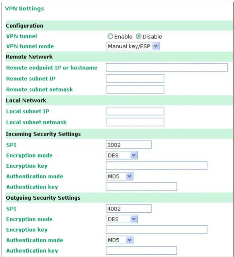
Configuration
VPN tunnel (default = Disable): Enable or disable the VPN tunnel function.
VPN tunnel mode: The type of VPN tunnel policy to be used; either manual key IPsec or ISAKMP with Pre-shared Keys (PSK).
Remote Network
Remote endpoint IP or hostname: Enter the WAN IP or hostname of the remote VPN server endpoint.
Remote subnet IP: Enter the remote VPN server subnet IP of the remote network.
Remote subnet netmask: Enter the remote VPN server subnet netmask of the remote network.
Local Network
Local subnet IP: Enter the local OnCell LAN subnet IP.
Local subnet netmask: Enter the local OnCell LAN subnet netmask.
Incoming Security Settings
SPI: This sets the VPN manual key incoming SPI between 257 and 4294967295.
Encryption mode: Select the incoming encryption mode.
Encryption key: Enter the incoming encryption key.
| Encryption mode Length (Bytes) | |
| DES 8 | |
| 3DES 24 | |
| AES 128bit 16 | |
| AES 192bit 24 | |
| AES 256bit 32 | |
Authentication mode: Select the incoming authentication mode.
Authentication key: Enter the incoming authentication key.
| Authentication mode Length (Bytes) | |
| MD5 16 | |
| SHA1 20 | |
Outgoing Security Settings
SPI: This sets the VPN manual key outgoing SPI between 257 and 4294967295.
Encryption mode: Select the outgoing encryption mode.
Encryption key: Enter the outgoing encryption key.
| Encryption mode Length (Bytes) | |
| DES 8 | |
| 3DES 24 | |
| AES 128bit 16 | |
| AES 192bit 24 | |
| AES 256bit 32 | |
Authentication mode: Select the outgoing authentication mode.
Authentication key: Enter the outgoing authentication key.
| Authentication mode Length (Bytes) | |
| MD5 16 | |
| SHA1 20 | |
ISAKMP/PSK
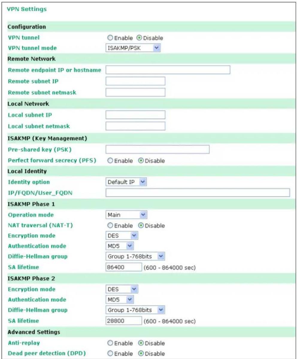
Configuration
VPN tunnel (default = Disable): Enable or disable the VPN tunnel function.
VPN tunnel mode: The type of VPN tunnel policy to be used; either manual key IPsec or ISAKMP with Pre-shared Keys (PSK).
Remote Network
Remote endpoint IP or hostname: Enter the WAN IP or hostname of the remote VPN server endpoint.
Remote subnet IP: Enter the remote VPN server subnet IP of the remote network.
Remote subnet netmask: Enter the remote VPN server subnet netmask of the remote network.
ISAKMP (Key Management)
Pre-shared key (PSK): This sets the VPN ISAKMP Pre-Shared key settings.
Perfect forward secrecy (PFS) (default = Disable): Enable or disable the Perfect Forward Secrecy. PFS is an additional security protocol.
Local Identity
Identity option: Select additional ID authentication requirements for the VPN using a specific IP Address, FQDN, or User FQDN settings.
IP/ FQDN/ User_FQDN: Enter an ID (IP/FQDN/User_FQDN) to identify and authenticate the local VPN endpoint.
ISAKMP phase 1
Operation mode: Select main mode or aggressive mode to configure the standard negotiation parameters for IKE Phase 1 of the VPN Tunnel.
NAT-T (default = Disable): Enabling this option will allow IPSec traffic from this endpoint to traverse through the translation process during NAT. The remote VPN endpoint must also support this feature and it must be enabled to function properly over the VPN.
Encryption mode: Select the VPN ISAKMP phase 1 encryption mode.
Authentication mode: Select the VPN ISAKMP phase 1 authentication mode.
Diffie-Hellman group: Select the VPN ISAKMP phase 1 DH group. As the DH Group number increases, the higher the level of encryption implemented for PFS
SA life time (default = 86400): Enter the number of seconds for the VPN ISAKMP phase 1 Lifetime. This is the period of time to pass before establishing a new IPSec security association (SA) with the remote endpoint.
ISAKMP phase 2
Encryption mode: Select the VPN ISAKMP phase 2 encryption mode.
Authentication mode: Select the VPN ISAKMP phase 2 authentication mode.
Diffie-Hellman group: Select the VPN ISAKMP phase 2 DH group. As the DH Group number increases, the higher the level of encryption implemented for PFS
SA life time (default = 28800): Enter the number of seconds for the VPN ISAKMP phase 2 Lifetime. This is the period of time to pass before establishing a new IPSec security association (SA) with the remote endpoint.
Advanced settings
Anti-replay (default = Disable): Anti-replay is the method of not allowing an intercepted packet message to be sent to the recipient multiple times without the original sender knowing.
Dead Peer Detection (DPD) (default = Disable): Enable or disable the Dead Peer Detection. DPD is a method of detecting a dead Internet Key Exchange (IKE) peer. It sends a DPD packet to the peer every 60 seconds under no traffic and attempt to connect normally. If the DPD packet fails 5 times the VPN will continuously re-establish a connection.
VPN system log events and error codes
| VPN system log Description | |
| VPN init. VPN tunnel initial | |
| VPN init. by packet VPN tunnel initial by packet | driven |
| VPN stop VPN tunnel stop | |
| VPN phase2 SA time out | VPN tunnel phase 2 security association time out |
| VPN time out | VPN tunnel connect time out |
| VPN has mismatched proposal VPN tunnel proposal not match | |
| VPN disconnected by change WAN IP | VPN tunnel disconnected by change WAN IP |
| VPN disconnected by DPD | VPN disconnected by Dead peer detection |
| VPN start phase1 main mode connect | VPN tunnel start phase 1 main mode connect |
| VPN start phase1 aggr. mode connect | VPN tunnel start phase1 aggressive mode connect |
| VPN start encryption VPN tunnel start encryption | |
| VPN phase1 pass | VPN tunnel phase 1 pass |
| VPN phase2 pass | VPN tunnel phase 2 pass |
| VPN Error Code 0001 ~ 0030 | VPN tunnel others error codeNote: For details refer to "Notify Messages - Error Types" in http://docbox.etsi.org/Reference/IETF/RFC/RFC2408.pdf |
| VPN phase2 renew key | VPN tunnel phase 2 renew key |
| VPN phase2 renew key success | VPN tunnel phase 2 renew key success |
| VPN phase1 SA time out | VPN tunnel phase 1 security association time out |
| VPN phase1 key(ISAKMP) deleted by remote | VPN tunnel phase 1 key(ISAKMP) deleted by remote |
| VPN phase2 key(ESP) deleted by remote | VPN tunnel phase 2 key(ESP) deleted by remote |
In this chapter, we describe additional serial port settings for the OnCell G3100. The same configuration options are also available through the Telnet and serial consoles.
The following topics are covered in this chapter:
□ Port Communication Parameters
Serial Parameters
□ Port Data Buffering/ Log
□ Port Chipher Settings
Port Communication Parameters
![Communication Parameters Port 1 Port alias Serial Parameters Baud rate [Hint] 115200 Data bits 8 Stop bits 1 Parity None Flow control RTS/CTS FIFO Enable Disable Interface RS-232 Submit](/content/2026/06/1160625/images/8167b102ba506f88b5f4b060a20084109782d62cce6a03e31e47557ea82e6daa.jpg)
Port alias: This optional field allows you to assign an alias to a port for easier identification.
Serial Parameters

ATTENTION
The serial parameters for the each serial port on the OnCell G3100 should match the parameters used by the connected serial device. You may need to refer to your serial device's user's manual to determine the appropriate serial communication parameters.
Baudrate (default=115200 bps): This field configures the port's baudrate. Select one of the standard baudrates from the dropdown box, or select Other and then type the desired baudrate in the input box.

ATTENTION
If the port requires a special baudrate that is not listed, such as 500000 bps, you may can select the Other option and enter the desired baudrate into the text box. The OnCell G3100 will automatically calculate the closest supported baudrate. The margin for error will be less than 1.7% for all baudrates under 921600 bps.
Data bits (default=8): This field configures the data bits parameter. Note: If data bits is set to 5 bits, stop bits will automatically be set to 2 bits.
Stop bits (default=1): This field configures the stop bits parameter. Note: If data bits is set to 5 bits, stop bits will automatically be set to 1.5 bits.
Parity (default=None): This field configures the parity parameter.
Flow control (default=RTS/CTS): This field configures the flow control type.
FIFO (default=Enable): This field enables or disables the 128-byte FIFO buffer. The OnCell G3100 provides FIFO buffers for each serial port, for both the Tx and Rx signals. Note, however, that you should disable the port's FIFO setting if the attached serial device does not have a FIFO buffer of its own. This is because a serial device that does not have its own buffer may not be able to keep up with data sent from the OnCell's FIFO buffer.
Interface (default=RS-232): You may configure the serial interface to RS-232, RS-422, RS-485 2-wire, or RS-485 4-wire.
Port Data Buffering/ Log
Data Buffering/Log
Port 1
Port buffering (256K)
Enable
Disable
Serial data logging (256K)
Enable
Disable
Submit
The OnCell G3100 supports port buffering to prevent the loss of serial data when the Cellular or Ethernet connection is down. Port buffering can be used in Real COM, Secure Real COM, Reverse Real COM, Secure Reverse Real COM, RFC2217, TCP Server, Secure TCP Server, TCP Client, Secure TCP Client, and SMS Tunnel modes. For other modes, the port buffering settings will have no effect.
Port buffering (default=Disable): You may enable port buffering by setting this field to Enable.
Serial data logging (default=Disable): If this field is set to Yes, the OnCell G3100 will store data logs on the system RAM for all serial ports. Note that this data is not saved when the OnCell G3100 is powered off.
Port Chipher Settings
Click Serial Port Settings → Chipher Settings to set the port chipher settings.
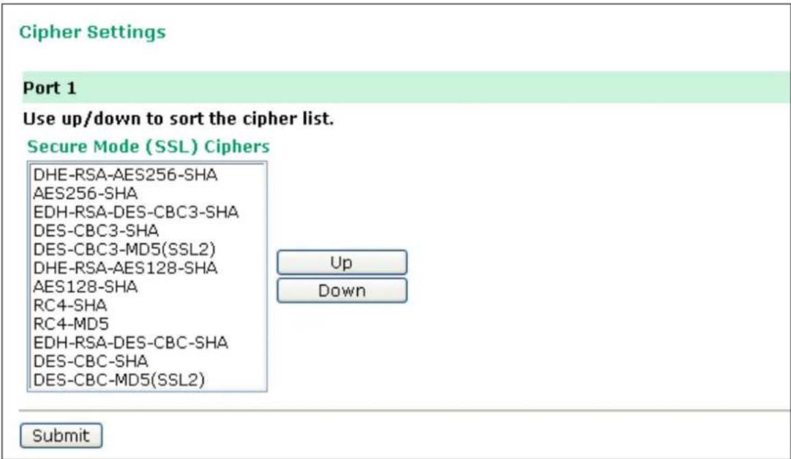
In this chapter, we describe additional server settings on the OnCell G3100. The same configuration options are also available through the Telnet and serial console.
The following topics are covered in this chapter:
□ Misc. Network Settings
Accessible IP List
SNMP Agent Settings
DDNS
Host Table
System Log Settings
▶ Virtual Server Settings
□ Auto Warning Settings
Event Settings
Serial Event Settings
E-mail Alert
SNMP Trap
SMS Alert
□ Maintenance
Console Setting
Ping
Manual SMS
Firmware Upgrade
Configuration Import/Export
Load Factory Defaults
Change Password
Remote SMS Control
□ Certificate
Ethernet SSL Certificate Import
▶ Certificate/Key Delete
□ System Monitoring
Serial to Network Connections
Serial Port Status
Serial Port Error Count
Serial Port Settings
▶ Chipher Usage Status
□ System Status
Serial Data Log
System Log
Dout State
▶ DIN and Power Status
□ Network Status
▶ Network Connections
Network Statistics
Routing
DHCP Client List
▶ Internet Sessions List
□ Save Configuration
□ Restart
▶ Restart System
Restart Ports
Misc. Network Settings
Accessible IP List
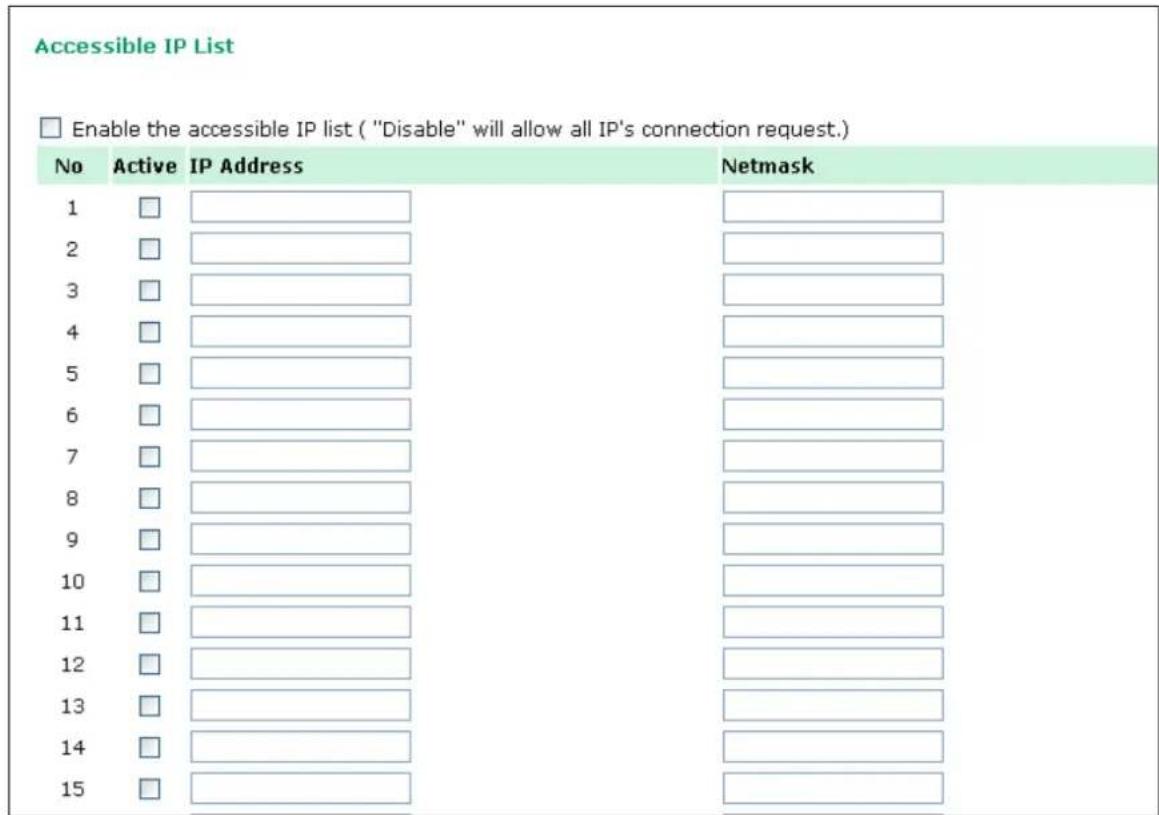
The OnCell G3100 uses an IP address-based filtering method to control access to its serial ports.
The Accessible IP list allows you restrict network access to the OnCell G3100. Access is controlled by IP address. When the accessible IP list is enabled, a host's IP address must be listed in order to gain access to the OnCell G3100. You may add a specific address or range of addresses by using a combination of IP address and netmask, as follows:
To allow access to a specific IP address
Enter the IP address in the corresponding field; enter 255.255.255.255 for the netmask.
To allow access to hosts on a specific subnet
For both the IP address and netmask, use 0 for the last digit (e.g., 192.168.1.0 and 255.255.255.0).
To allow unrestricted access
Deselect the Enable the accessible IP list option.
Refer to the following table for more configuration examples.
| Allowed hosts Entered IP address/ Netmask | |
| Any host Disable | |
| 192.168.1.120 | 192.168.1.120 / 255.255.255.255 |
| 192.168.1.1 to 192.168.1.254 | 192.168.1.0 / 255.255.255.0 |
| 192.168.0.1 to 192.168.255.254 | 192.168.0.0 / 255.255.0.0 |
| 192.168.1.1 to 192.168.1.126 | 192.168.1.0 / 255.255.255.128 |
| 192.168.1.129 to 192.168.1.254 | 192.168.1.128 / 255.255.255.128 |
SNMP Agent Settings
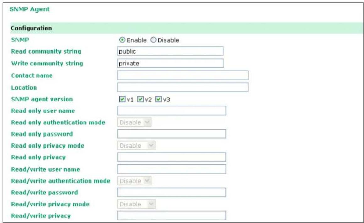
SNMP: To enable the SNMP Agent function, select the Enable option, and enter a community name (e.g., public).
Read community string (default=public): This is a text password mechanism that is used to weakly authenticate queries to agents of managed network devices.
Write community string (default=private): This is a text password mechanism that is used to weakly authenticate changes to agents of managed network devices.
Contact name: The optional SNMP contact information usually includes an emergency contact name and telephone or pager number.
Location: Use this optional field to specify the location string for SNMP agents such as the OnCell G3100. This string is usually set to the street address where the OnCell G3100 is physically located..
SNMP agent version: The OnCell G3100 supports SNMP V1, V2, and V3.
Read-only and Read/ Write Access Control
The following fields allow you to define user names, passwords, and authentication parameters for two levels of access: read-only and read/write. The name of the field will indicate which level of access it refers to. For example, Read only authentication mode allows you to configure the authentication mode for read-only access, whereas Read/write authentication mode allows you to configure the authentication mode for read/write access. For each level of access, you may configure the following:
User name: Use this optional field to identify the user name for the specified level of access.
Authentication mode (default=Disable): Use this field to select MD5 or SHA as the method of password encryption for the specified level of access, or to disable authentication
Privacy mode (default= Disable): Use this field to enable or disable DES_CBC data encryption for the specified level of access.
Password: Use this field to set the password for the specified level of access.
Privacy: Use this field to define the encryption key for the specified level of access.
DDNS
Please refer to Appendix C, Dynamic Domain Name Server, for information on setting up DDNS on your OnCell G3100.
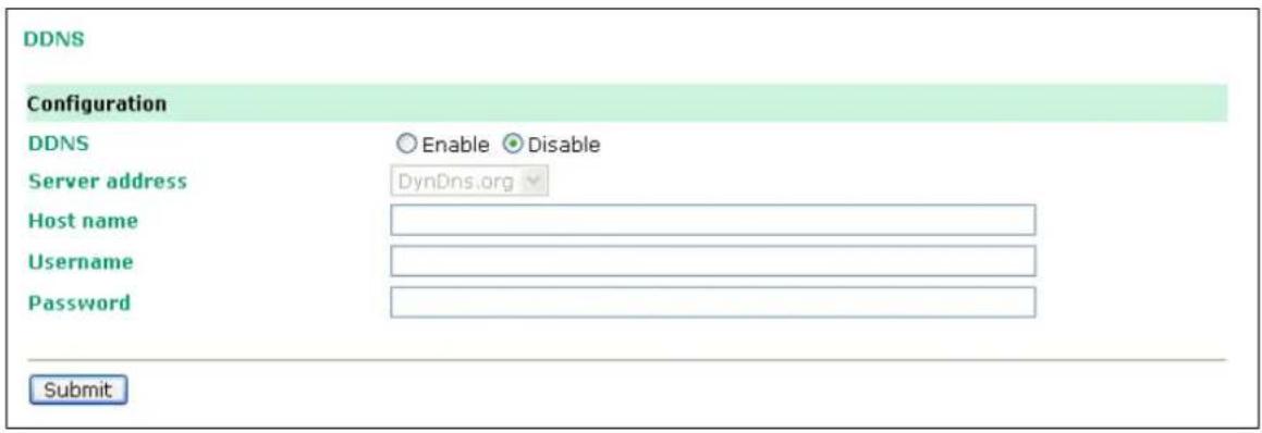
Host Table
| Host Table | ||
| No | Host Name | Host IP Address |
| 1 | ||
| 2 | ||
| 3 | ||
| 4 | ||
| 5 | ||
| 6 | ||
| 7 | ||
| 8 | ||
| 9 | ||
| 10 | ||
| 11 | ||
| 12 | ||
| 13 | ||
| 14 | ||
| 15 | ||
| 16 | ||
The Host Table can be used to simplify IP address entry in the OnCell G3100 console by assigning a Host Name to a Host IP Address. When you assign a Host Name to a Host IP Address, you can then use the Host Name for some fields on the console rather than entering the IP address. Up to 16 entries can be stored in the Host Table.
System Log Settings
| System Log Settings | ||
| Event Group | Local Log | Summary |
| System | System Cold Start, System Warm Start, Power 1 DOWN, Power 2 DOWN, Cell. module awake/fail, Cell. module close/over temperature range | |
| Network | DHCP/BOOTP/PPP Get IP/Renew, NTP, Mail Fail, NTP Connect Fail, IP Conflict, Network Link Down, Cell. moudle get/lost IP | |
| Config | Login Fail, IP Changed, Password Changed, Config Changed, Firmware Upgrade, SSL Certificate Import, Delete SSL Certificate/Key, Config Import, Config Export | |
| OpMode | Connect, Disconnect, Restart | |
| Input | Din 1 turn on, Din 1 turn off, Din 2 turn on, Din 2 turn off | |
| Submit | ||
System Log Settings allows the administrator to customize which network events are logged by the OnCell G3100. Events are grouped into five categories, known as event groups, and the administrator selects which groups to log under Local Log. The actual system events that would be logged for each system group are listed under summary. For example, if System was enabled, then System Cold Start events and System Warm Start events would be logged.
| Group Event | |
| System | System Cold Start, System Warm Start, Power 1 DOWN, Power 2 DOWN, Cell. module awake/fail, Cell. module close/over temperature range |
| Network | DHCP/BOOTP Get IP/Renew, NTP, Mail Fail, NTP Connect Fail, IP Conflict, Network Link Down, Cell. module get/lost IP |
| Config | Login Fail, IP Changed, Password Changed, Config Changed, Firmware Upgrade, SSL Key Import, Config Import, Config Export |
| OpMode Connect, Disconnect, Restart | |
| Input | Din 1 turn on, Din 1 turn off, Din 2 turn on, Din 2 turn off |
Virtual Server Settings
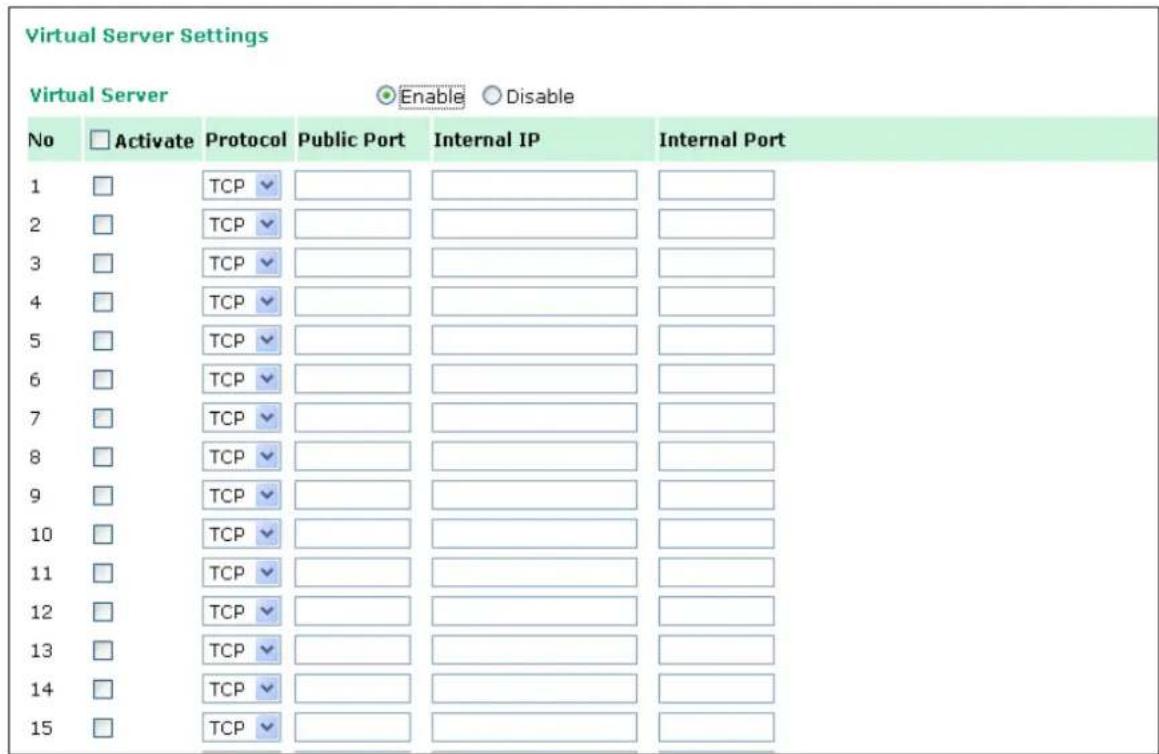
Virtual Server Settings (default=Disable): This function allows remote users to access the Host or FTP services via a public IP address, and automatically redirects them to local servers in the LAN (Local Area Network).
The OnCell firewall feature filters out unrecognized packets to protect your LAN network when computers networked with the OnCell are hidden from public view. If you wish, you can make some of the LAN computers accessible from the Internet by enabling Virtual Server. Depending on the requested service, the OnCell redirects the external service request to the appropriate server within the LAN network.
The OnCell is also capable of port-redirection meaning incoming traffic to a particular port may be redirected to a different port on the server computer.
Public Port: The public port is the port seen from the Internet side. Public ports cannot be set to ports used by OP modes (950, 966, 4001...etc)
Internal IP: Enter the IP address of the host on your local network that you want to allow the incoming service to.
Internal Port: The internal port is the port being used by the application on the host within your local network.
Auto Warning Settings
Event Settings
| Event Settings | ||||
| System Event | ||||
| Cold start | Trap | SMS | ||
| Warm start | Trap | SMS | ||
| Network Event | ||||
| Ethernet link down | Dout | SMS | ||
| Config Event | ||||
| Console(web/text) login auth fail | Trap | SMS | ||
| IP changed | SMS | |||
| Password changed | SMS | |||
| Power Event | ||||
| Power 1 fail | Dout | SMS | ||
| Power 2 fail | Dout | SMS | ||
| Din Event | ||||
| Din 1 turn on (trigger) | Dout | SMS | ||
| Din 1 turn off (trigger) | Dout | SMS | ||
| Din 2 turn on (trigger) | Dout | SMS | ||
| Din 2 turn off (trigger) | Dout | SMS | ||
| Cellular Module Event | ||||
| Cell. module fail | Dout | |||
| Cell. close temperature range | Dout | SMS | ||
| Cell. over temperature range | Dout | |||
On the Event Settings page, you may configure how administrators are notified of certain system, network, configuration, power, Din, and cellular module events. Depending on the event, different options for automatic notification are available, as shown above. Mail refers to sending an e-mail to a specified address. Trap refers to sending an SNMP Trap. Dout is available on the network, power, Din, and cellular module event. SMS refers to sending a message to a specified phone number.
Cold start: This refers to starting the system from a power off state, or after upgrading your firmware
Warm start: This refers to restarting the OnCell G3100 without turning the power off.
Network Event: These settings configure the OnCell to change the status of the relay output and SMS if the specified connection goes down.
Console (web/ text) login auth fail: This field refers to a failed attempt to log in to a password protected OnCell G3100 console.
IP changed: With this IP address change, the OnCell G3100 will send and email or SMS warning after it reboots.
Password changed: With this option selected, the OnCell G3100 will attempt to send an e-mail or SMS warning after it reboots with a new console password. If the OnCell G3100 is unable to send an e-mail or SMS message to the mail server within 15 seconds, it will still reboot without sending the e-mail or SMS.
Power event: The OnCell G3100 provides two DC power inputs for redundancy. If either power fails, the OnCell G3100 will attempt to send an e-mail warning, relay output, or SMS.
Din event: When the status of digital input 1 or 2 is changed, the OnCell G3100 will attempt to send an e-mail, trigger the digital output, or send an SMS.
Cell. module fail: When the cellular module fails to function, the OnCell G3100 will attempt to send an e-mail, or trigger the digital output to inform users.
Cell. close temperature range: When the temperature on the cellular module inside the OnCell G3100 is close to the upper or lower limit, the OnCell G3100 will attempt to send an e-mail, trigger the digital output, or send an SMS message to inform users.
Cell. over temperature range: When the temperature on the cellular module inside the OnCell G3100 is outside the normal temperature range, the OnCell G3100 will attempt to send an e-mail, or trigger the digital output to inform users.
Serial Event Settings
Port Event Settings
| Serial Port Event | DCD changed | DSR changed | ||||||
| Port 1 | □ Trap | □ Dout | □ SMS | □ Trap | □ Dout | □ SMS | ||
| Submit | ||||||||
On the Serial Event Settings page, you may configure how administrators are notified of each serial port's DCD and DSR changes. Mail refers to sending an e-mail to a specified address. Trap refers to sending an SNMP Trap. Dout refers to changing the status of the relay output. SMS refers to sending a message to one or more specified phone numbers.
DCD changed
A change in the DCD (Data Carrier Detect) signal indicates that the modem connection status has changed. For example, if the DCD signal changes to low, it indicates that the connection line is down. When the DCD signal changes to low, the OnCell G3100 will automatically send a warning to the administrator as configured on the Serial Event Settings page.
For relay output function, after the relay output status has been changed, administrators may reset its status by selecting Acknowledge Event from the OnCell G3100 console, or by correcting the DCD signal. Please refer to the section on System Monitoring later in this chapter for more information.
DSR changed
A change in the DSR (Data Set Ready) signal indicates that the data communication equipment is powered off. For example, if the DSR signal changes to low, it indicates that the data communication equipment is powered down. When the DSR signal changes to low, the OnCell G3100 will automatically send a warning to the administrator as configured on the Serial Event Settings page.
For relay output function, after the relay output status has been changed, administrators may reset its status by selecting Acknowledge Event from the OnCell G3100 console, or by correcting the DSR signal. Please refer to the section on System Monitoring later in this chapter for more information.

ATTENTION
SNMP indicates a change in DCD or DSR signals but does not differentiate between the two. A change in either signal from “−” to “+” is indicated by “link up” and a change in either signal from “+” to “−” is indicated by “link down.”
E-mail Alert
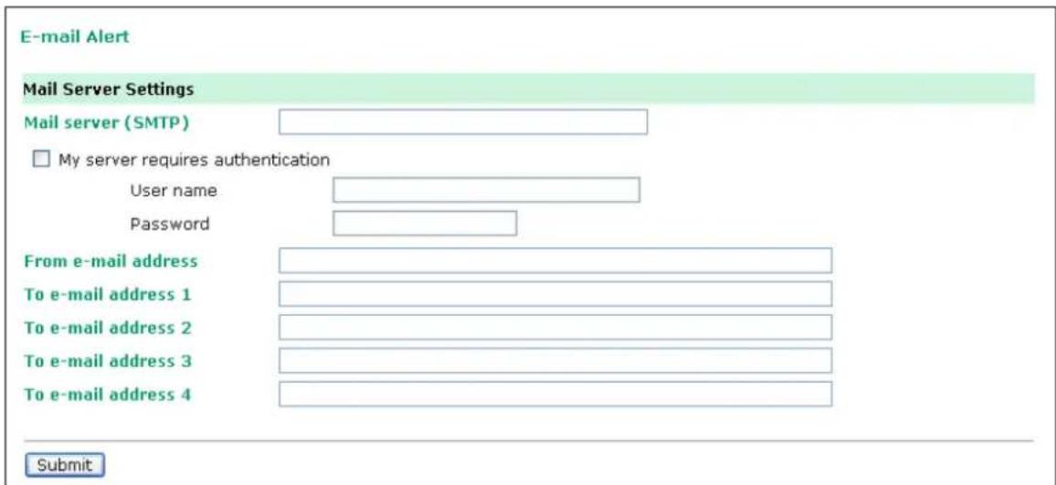
The E-mail Alert settings determine how e-mail warnings are sent for system and serial port events. You may configure up to 4 e-mail addresses to receive automatic warnings.

ATTENTION
Consult your Network Administrator or ISP for the proper mail server settings. The Auto warning function may not work properly if it is not configured correctly. The OnCell G3100's SMTP AUTH supports LOGIN, PLAIN, and CRAM-MD5 (RFC 2554).
Mail server: This field is for your mail server's domain name or IP address.
User name: This field is for your mail server's user name, if required.
Password: This field is for your mail server's password, if required.
From e-mail address: This is the e-mail address from which automatic e-mail warnings will be sent.
To e-mail address 1 to 4: This is the e-mail address or addresses to which the automatic e-mail warnings will be sent.
SNMP Trap
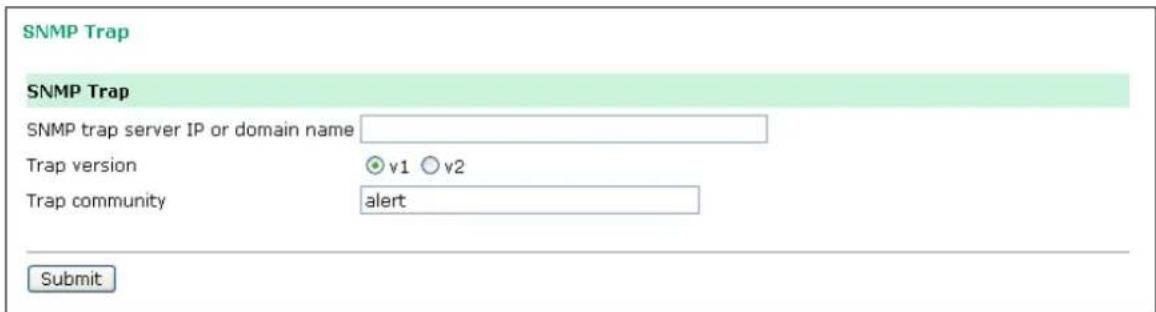
SNMP trap server IP: Use this field to indicate the IP address to use for receiving SNMP traps.
Trap version (default=v1): Use this field to select the SNMP trap version.
Trap community (default=alert): Use this field to designate the SNMP trap community.
SMS Alert
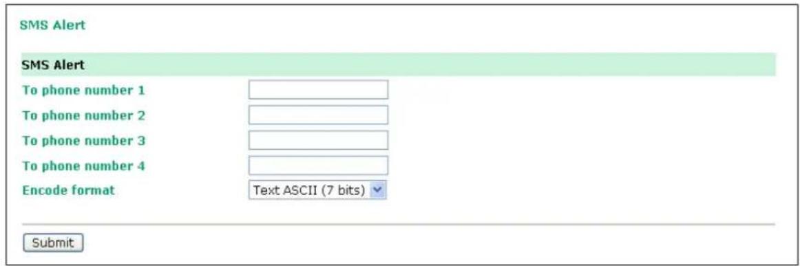
To phone number 1 to 4: This is the phone number to which the automatic warnings message will be sent.
Encode format:
| SMS Data Format | |
| Text ASCII (7 bits) (default) | 7 bits text format (160 bytes per packet) |
| Binary 8 bits binary (140 bytes per packet) | |
| Unicode 16 bits Unicode (UCS2) format (70 bytes per packet) | |
Customized SMS
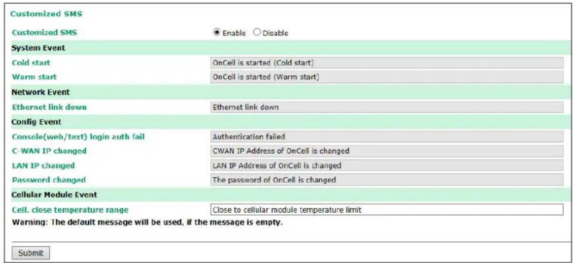
Customized SMS Settings: (default=Disable): Enable this function to allow customized SMS warnings and events to be sent to the phone numbers configured in the SMS Alert section.
Remote Management
Remote SMS Control
Remote SMS Control can be used when your OnCell devices are installed in locations that are not easy to access and where GPRS service is unstable. SMS service is one of the most reliable cellular services. Remote SMS control provides: 1) the ability to report the current status of the OnCell device to your SMS sender; 2) the ability to reboot the device so it can be recovered from any unexpected situation.
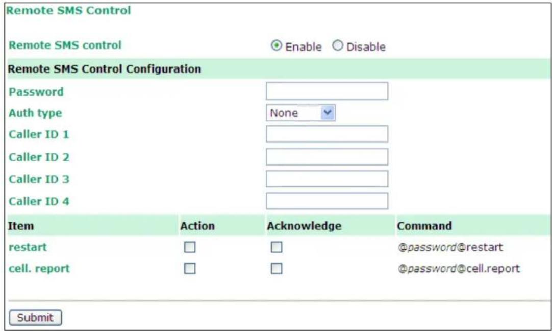
Remote SMS Control: Enable or disable the ability of the OnCell to be controlled by SMS (default: disabled). Password: Set your password (4-16 characters).
Auth type: You can restrict the access by enabling the Caller ID under Auth Type.
Caller ID: Enter Caller ID number so that only SMS from specific senders can trigger Remote SMS control.
restart: When receiving the SMS message [@password@restart], the device will reboot. Ex. If
Password=12345, then sending an SMS notification that reads @12345@restart to the OnCell will reboot the OnCell.
cell. report: When receiving the SMS message [@password@cell.report], the device will reply with the current cellular status.
Action: Execute an operation upon receiving an SMS notification.
Acknowledge: Reply to the SMS sender with an SMS message after the operation is completed.
Example: If Password=12345, then sending an SMS notification that reads @12345@cell.report to the OnCell will cause the OnCell device to send an SMS response detailing its cellular status.
Manual SMS
The manual SMS feature allows you to send text messages through the web console interface. Simply enter the SMS recipient's phone number and the content of your message and click the "Send" button to send your text message. After the SMS is sent, the UI will show the entry number, the time it was sent, the destination phone number and whether the SMS was successfully sent or not.
![Manual SMS Manual Sending SMS Settings Phone number SMS content Max length is 160. The remain length is 160. Warning: For some characters (e.g. '^', '\\', 'I', 'o', '[, ], '.', ('', and '')'), two bytes are required. Send Sending Result No. Time To Result](/content/2026/06/1160625/images/1f9b577b62f52e600fe9d58ac2f8c2f07a8aa14466299eea85ab3ede98670bc9.jpg)
Remote Caller ID
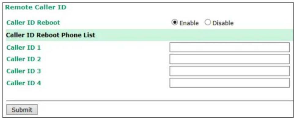
Remote Caller ID can be used to instantly reboot OnCell devices installed in locations that are not easy to access and where GPRS/3G service is unstable. The remote caller ID function allows users to input up to 4 cell phone numbers (Caller ID 1, ...). Only calls from these 4 numbers will cause the OnCell to reboot.
Maintenance
Console Settings
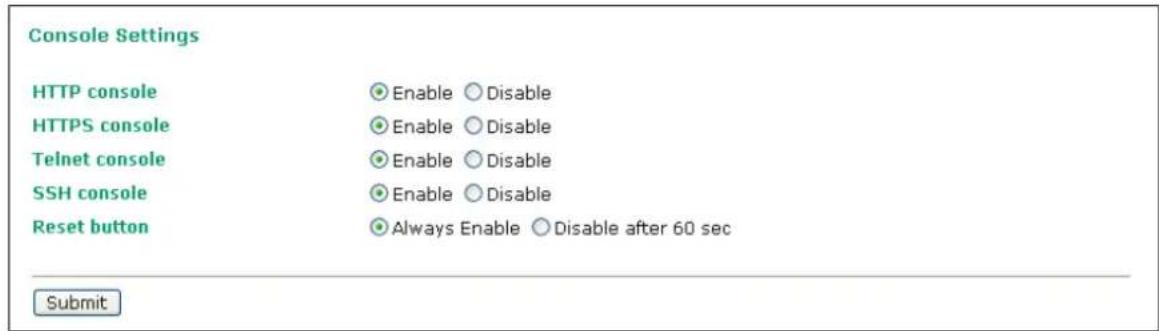
On this screen, access to different OnCell G3100 configuration console options (HTTP, HTTPS, Telnet, SSH) can be enabled or disabled. Please refer to Change Password later in this chapter for more information on passwords. Finally, you may also enable or disable the reset button.
Enable(default): always workable
Disable after 60 sec: Reset button will not workable after 60 sec. This is protect reset button for incidental press
Ping

You can ping an IP address from the OnCell G3100 web console in order to test the Ethernet connection. Enter the IP address or domain name in the Destination field to make sure that the connection is OK.
Firmware Upgrade
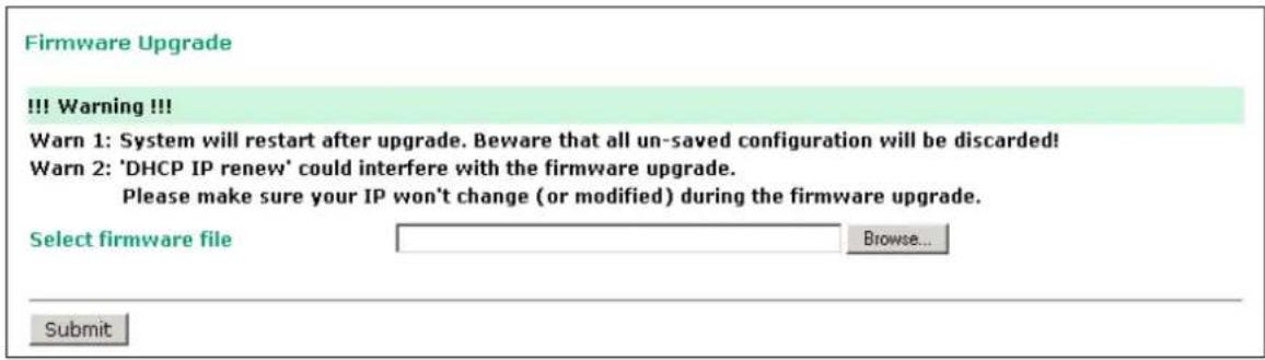
The OnCell G3100's firmware can be upgraded though the web console, serial console, or through OnCell Search Utility. If you have made any changes to your configuration, remember to save the configuration first before upgrading the firmware. Please refer to Save Configuration later in this chapter for more information. Any unsaved changes will be discarded when the firmware is upgraded. To upgrade the firmware, simply enter the file name and click Submit. The latest firmware can be downloaded from www.moxa.com.
Configuration Import/ Export
The OnCell G3100 can share or back up its configuration by exporting all settings to an encrypted file.
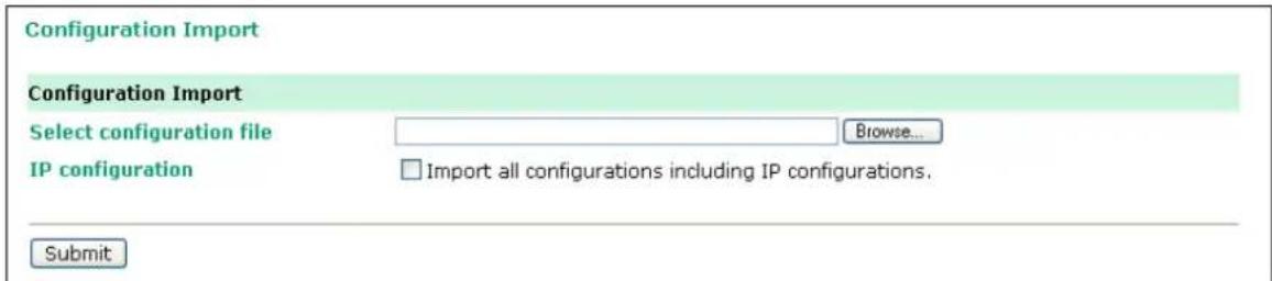
To import a configuration, go to System Management → Maintenance → Configuration Import. Enter the configuration file path/name and click Submit. The OnCell G3100's configuration settings will be updated according to the configuration file. If you also wish to import the IP configuration (i.e., the OnCell G3100's IP address, netmask, gateway, etc.), make sure that Import all configurations including IP configurations is checked on.

To export a configuration, go to System Management → Maintenance → Configuration Export and click Download. A standard download window will appear, and you will be able to download the configuration into a file name and location of your choice.
Load Factory Defaults
Load Factory Default
Click on Submit to reset all settings, including the console password, to the factory default values. To leave the network-related settings unchanged, make sure that Keep IP Settings is enabled.
Reset to Factory Default
√ Keep IP settings
Submit
This function will reset all of OnCell G3100's settings to the factory default values. All previous settings including the console password will be lost. If you wish to keep the OnCell G3100 IP address, netmask, and other IP settings, make sure Keep IP settings is checked off before loading the factory defaults.
Change Password
Change Password
Password
Old password
New password
Confirm password
Submit
For all changes to the OnCell G3100's password protection settings, you will first need to enter the old password. Leave this blank if you are setting up password protection for the first time. To set up a new password or change the existing password, enter your desired password under both New password and Confirm password. To remove password protection, leave the New password and Confirm password boxes blank.

ATTENTION
If you forget the password, the ONLY way to configure the OnCell G3100 is by using the reset button on the OnCell G3100's casing to load the factory defaults.
Before you set a password for the first time, it is a good idea to export the configuration to a file when you have finished setting up your OnCell G3100. Your configuration can then be easily imported back into the OnCell G3100 if you need to reset the OnCell G3100 due to a forgotten password or for other reasons. Please refer to the section on Configuration Import/Export earlier in this chapter for more details.
Certificate
Ethernet SSL Certificate Import
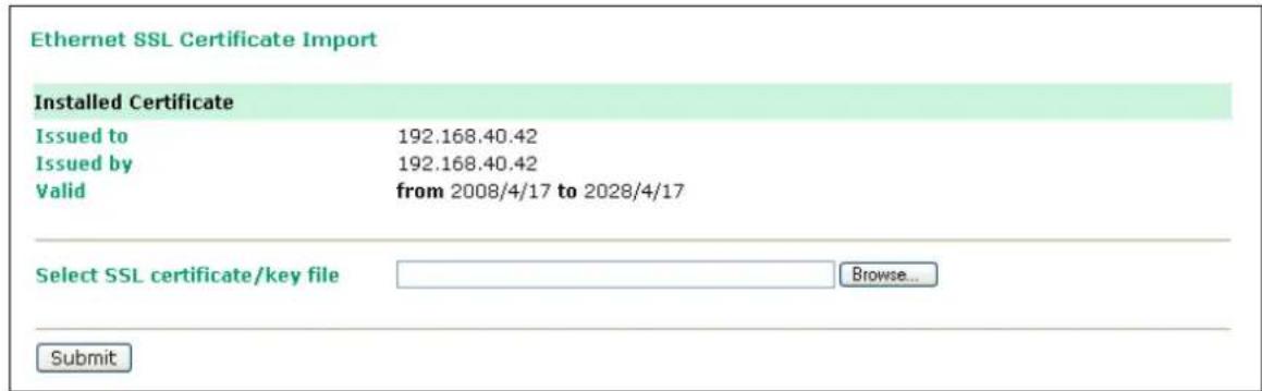
SSL certificate is used to ensure the website you are accessing is the one you trust, and to encrypt the data transmitted between you and the website. The SSL certificate contains unique, authenticated information about the certificate owner. It is issued by a Certificate Authority (CA), such as Verisign, that verifies the identity of the certificate owner.
The OnCell G3100 series will generate a new SSL certificate whenever a new IP is used. However, the SSL certificate is issued by the OnCell itself. If you would like to import an SSL certificate issued by a primary CA, you can do it from the "Ethernet SSL Certificate Import" page.
Certificate/ Key Delete

You can delete an SSL certificate on this page. To do so, select the Delete option and then click on the Submit button.
System Monitoring
Serial to Network Connections
Go to Serial to Network Connections under Serial Status to view the operation mode and status of each connection for each serial port. All monitor functions will refresh automatically every 15 seconds.
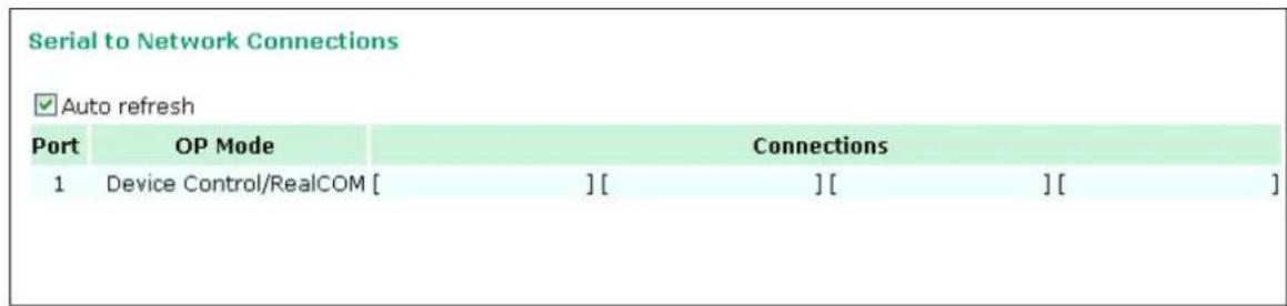
Serial Port Status
Go to Serial Port Status under Serial Status to view the current status of each serial port. Serial Port Status → Buffering monitors port buffering usage (bytes) of the serial port. A green dot indicates active, and a gray dot indicates inactive

Serial Port Error Count
Go to Serial Port Error Count under Serial Status to view the error count for each serial port.
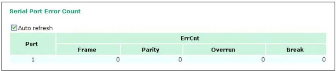
Serial Port Settings
Go to Serial Port Settings under Serial Status to view a summary of the settings for each serial port.
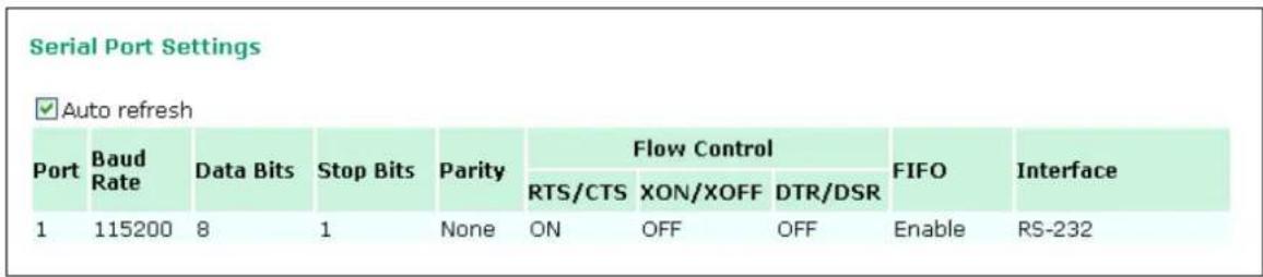
Chipher Usage Status
| Cipher Usage Status | |||
| ✓ Auto refresh | |||
| Port | OP Mode | Connections | Cipher |
| 1 | Device Control/RealCOM | ||
Click Serial Status → Chipher Usage Status to monitor chipher usage and connection status of each serial port. The Cipher Usage Status is dependent on the Chipher Settings.
System Status
Serial Data Log
Data logs for the serial port can be viewed in ASCII or HEX format. After selecting the serial port and format, you may click Select all to select the entire log if you wish to copy and paste the contents into a text file.
![Serial Data Log Data Log - ASCII Select port Port1 [ASCII][HEX] Select all Clear log Refresh](/content/2026/06/1160625/images/9fa6b88d3cb1e58cc4e2a3fc9cc08d29f60eb76fd80c55cc98b42d8dab402bba.jpg)
System Log
This option displays the system log. You may click Select all to select the entire log if you wish to copy and paste the contents into a text file.
![System Log System Log 2000/01/30 17:41:06 [System] System Cold Start 2000/01/30 18:17:19 [Network] Ethernet Link Down 2000/02/02 11:15:12 [Network] Ethernet Link Down 2000/02/03 17:13:06 [System] Power 2 DOWN 2000/02/03 17:13:06 [System] System Cold Start 2000/02/03 17:25:06 [System] Power 2 DOWN 2000/02/03 17:25:06 [System] System Cold Start 2000/02/03 17:25:48 [Network] Cell. module gets an IP 114.137.32.29 2000/02/03 17:25:48 [Config] IP Changed 2000/02/03 17:32:50 [Network] Ethernet Link Down 2000/02/03 17:33:33 [Config] Config Changed 2000/02/03 17:33:42 [System] Power 2 DOWN 2000/02/03 17:33:42 [System] System Warm Start 2000/02/03 17:35:59 [OpMode] PortO2 Connect 192.168.127.31:5448 2000/02/03 17:37:51 [OpMode] PortO2 Disconnect 2000/02/04 15:24:06 [System] Power 2 DOWN 2000/02/04 15:24:06 [System] System Cold Start 2000/02/04 15:27:06 [Network] Ethernet Link Down 2000/02/04 15:27:09 [Network] Ethernet Link Down 2000/02/04 15:27:30 [Config] Delete SSL Certificate/Key Select all Clear log Refresh](/content/2026/06/1160625/images/3d33f27a1406651c4deb15d6eb9c6a56d1db065de5d621748229901d646d6b23.jpg)
Dout State
Dout State refers to the relay output status, which can be configured to change upon the occurrence of certain system events through Auto Warning Settings under System Management. You may click Dout State under System Status to display a list of events that may cause a change to the Dout state. If a configured alarm event occurs, the Dout state changes, and you may come to this screen to determine the specific cause for the alarm. To reset the Dout state, click on Acknowledge Event.
| Dout State | ||
| Auto refresh | ||
| Dout Status | ||
| Ethernet link down | --- | Acknowledge Event |
| Power 1 down | --- | Acknowledge Event |
| Power 2 down | --- | Acknowledge Event |
| Din 1 on | --- | Acknowledge Event |
| Din 1 off | --- | Acknowledge Event |
| Din 2 on | --- | Acknowledge Event |
| Din 2 off | --- | Acknowledge Event |
| Cell. module fail | --- | Acknowledge Event |
| Cell. close temperature range | --- | Acknowledge Event |
| Cell. over temperature range | --- | Acknowledge Event |
| DCD changed (Port 1) | --- | Acknowledge Event |
| DSR changed (Port 1) | --- | Acknowledge Event |
DIN and Power Status
Go to Din and Power status under System Status to display the power and digital input information.
| Din and Power status | |
| Auto refresh | |
| Input Status | ON / OFF |
| Power 1 status | ON |
| Power 2 status | OFF |
| Din 1 status | OFF |
| Din 2 status | OFF |
Network Status
Network Connections
Go to Network Connections under System Status to view network connection information.
Network Connections
Auto refresh
| Protocol | Recv-Q | Send-Q | Local Address | Foreign Address | State |
| TCP | 0 | 0 | 192.168.127.254:8000 | *:* | LISTEN |
| TCP | 0 | 0 | 192.168.127.254:4900 | *:* | LISTEN |
| TCP | 0 | 0 | 192.168.127.254:14900 | *:* | LISTEN |
| TCP | 0 | 0 | 192.168.127.254:80 | *:* | LISTEN |
| TCP | 0 | 0 | 192.168.127.254:443 | *:* | LISTEN |
| TCP | 0 | 0 | 192.168.127.254:23 | *:* | LISTEN |
| TCP | 0 | 0 | 192.168.127.254:22 | *:* | LISTEN |
| TCP | 0 | 0 | 192.168.127.254:950 | *:* | LISTEN |
| TCP | 0 | 0 | 192.168.127.254:966 | *:* | LISTEN |
| TCP | 0 | 0 | 192.168.127.254:80 | 169.254.132.0:3037 | ESTAB |
| TCP | 0 | 0 | 192.168.127.254:80 | 169.254.132.0:3039 | ESTAB |
Network Statistics
Go to Network Statistics under System Status to view network statistics.
Network Statistics
Auto refresh
| ETHERNET | Received | 1372 | Sent | 2688 | ||
| PPP | Received | 0 | Sent | 0 | ||
| RDiscard | 0 | ErrSum | 0 | SDiscard | 0 | |
| Received | 1366 | Sent | 2671 | |||
| IP | RDiscard | 0 | SNoRoute | 0 | SDiscard | 0 |
| ErrHeader | 0 | ErrProto | 0 | ErrAddr | 0 | |
| ICMP | Received | 0 | Sent | 0 | ||
| REchoReq | 0 | SEchoReq | 0 | |||
| REchoRply | 0 | SEchoRply | 0 | |||
| UDP | Received | 26 | Sent | 21 | ||
| ErrHeader | 0 | ErrPorts | 0 | |||
| TCP | Received | 1271 | Sent | 2650 | ||
| ErrHeader | 0 | ErrPorts | 0 | ReSent | 16 | |
| CurrEstab | 2 | Opens | 6 |
Routing
Go to Routing under System Status to display the routing information.
Routing
Auto refresh
Current Routing
| Iface | Destination | Gateway/HA | Netmask | Metric | Flag | Use |
| LAN | 192.168.127.0 | 192.168.127.254 | 255.255.255.0 | 1 | U+ | 2760 |
Possible flags include:
U: route is up
D: route is down
G: use gateway
+: default gateway
T: static route
H: target is a host
\* Client List
The DHCP Client List shows all the clients that require and have successfully received IP assignments. Check the Refresh box to refresh the list.
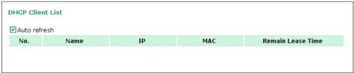
Internet Sessions List
| Internet Sessions | ||||||||
| ✓Auto refresh | ||||||||
| No | Local | NAT Port | Internet | Protocol | State | Direction | Time Out | |
| 1 | 168.1.0.0:33072 | 6 | 152.137.1.0:87 | UDP | NONE | IN | 35s | |
| 2 | 168.1.0.0:33072 | 6 | 152.137.1.0:87 | UDP | NONE | IN | 35s | |
| 3 | 168.1.0.0:33072 | 6 | 152.137.1.0:87 | UDP | NONE | IN | 35s | |
| 4 | 168.1.0.0:33072 | 6 | 152.137.1.0:87 | UDP | NONE | IN | 35s | |
| 5 | 168.1.0.0:33072 | 6 | 152.137.1.0:87 | UDP | NONE | IN | 35s | |
| 6 | 168.1.0.0:33072 | 6 | 152.137.1.0:87 | UDP | NONE | IN | 35s | |
| 7 | 168.1.0.0:33072 | 6 | 152.137.1.0:87 | UDP | NONE | IN | 35s | |
| 8 | 168.1.0.0:33072 | 6 | 152.137.1.0:87 | UDP | NONE | IN | 35s | |
| 9 | 168.1.0.0:33072 | 6 | 152.137.1.0:87 | UDP | NONE | IN | 35s | |
| 10 | 168.1.0.0:33072 | 6 | 152.137.1.0:87 | UDP | NONE | IN | 35s | |
| 11 | 168.1.0.0:33072 | 6 | 152.137.1.0:87 | UDP | NONE | IN | 35s | |
| 12 | 168.1.0.0:33072 | 6 | 152.137.1.0:87 | UDP | NONE | IN | 35s | |
| 13 | 168.1.0.0:33072 | 6 | 152.137.1.0:87 | UDP | NONE | IN | 35s | |
| 14 | 168.1.0.0:33072 | 6 | 152.137.1.0:87 | UDP | NONE | IN | 35s | |
| 15 | 168.1.0.0:33072 | 6 | 152.137.1.0:87 | UDP | NONE | IN | 35s | |
| 16 | 168.1.0.0:33072 | 6 | 152.137.1.0:87 | UDP | NONE | IN | 35s | |
| 17 | 168.1.0.0:33072 | 6 | 152.137.1.0:87 | UDP | NONE | IN | 35s | |
| 18 | 168.1.0.0:33072 | 6 | 152.137.1.0:87 | UDP | NONE | IN | 35s | |
| 19 | 168.1.0.0:33072 | 6 | 152.137.1.0:87 | UDP | NONE | IN | 35s | |
| 20 | 168.1.0.0:33072 | 6 | 152.137.1.0:87 | UDP | NONE | IN | 35s | |
| 21 | 208.7.0.0:4 | OgOgOgOgOgOgOgOgOgOgOgOgOgOgOgOgOgOgOgOgOgOgOgOgOgOgOgOgOgOgOgOgOgOgOgOgOgOgOgOgOgOgOgOgOgOgOgOgOgOgOogOgOgOgOgOgOgOgOgOgOgOgOgOgOgOgOgOgOgOgOgOgOgOgOgOgOgOgOgOgOgOgOgOgOgOgOgOgOgOgOgOgOgOgOgOgOgOgOgOgOc 22 23 24 25 26 27 28 29 30 31 32 33 34 35 36 37 38 39 40 41 42 43 44 45 46 47 48 49 50 51 52 53 54 55 56 57 58 59 60 61 62 63 64 65 66 67 68 69 70 71 72 73 74 75 76 77 78 79 80 81 82 83 84 85 86 87 88 89 90 91 92 93 94 95 96 97 98 99 100 101 102 103 104 105 106 107 108 109 110 111 112 113 114 115 116 117 118 119 120 121 122 123 124 125 126 127 128 129 130 131 132 133 134 135 136 137 138 139 140 141 142 143 144 145 146 147 | ||||||
The Internet Sessions page displays full details of active Internet sessions through your router. An Internet session is a conversation between a program or application on a LAN-side computer and a program or application on a WAN-side computer or device.
Save Configuration
Go to Save Configuration and then click Save to save your submitted configuration changes to the OnCell G3100's flash memory. The configuration changes will be effective when the OnCell G3100 is restarted. If you do not save your changes before restarting, they will be discarded.
Save Configuration
If you have submitted any configuration changes, you must save the changes and restart the server before they take effect. Click Save to save the changes in the OnCell G3100's memory. To restart the server, go to Restart System in the navigation panel.
Save
Restart
Restart System
Go to Restart System under Restart and then click Restart to restart the OnCell G3100. Ensure that you save all of your configuration changes before you restart the system or else these changes will be lost.
Restart System
!!! Warning !!!
Clicking Restart will disconnect all serial and Ethernet connections and reboot the OnCell G3100 server. NOTE: Unsaved configuration changes will be discarded, and data currently in the middle of transmission may be lost.
Restart
Restart Ports
Go to Restart Ports under Restart and then select the ports to be restarted. Click Select All to select all the ports. Click Submit to restart the selected ports.
Restart Ports
Restart the selected serial ports.
Select Ports
□1
Select All
Submit
The following topics are covered in this chapter:
Overview
□ Windows Driver Manager
➢ Installing Windows Driver Manager
➢ Using Windows Driver Manager
□ OnCell Search Utility
Installing OnCell Search Utility
➢ Configuring OnCell Search Utility
□ Moxa OnCell Linux Real TTY Driver
Basic Procedure
Hardware Setup
➢ Installing Linux Real TTY Driver Files
Mapping TTY Ports
Removing Mapped TTY Ports
Removing Linux Driver Files
☐ Moxa OnCell UNIX Fixed TTY Driver
Installing the UNIX Driver
- Configuring the UNIX Driver
Overview
To ensure that installation and configuration are easy and straightforward, download the following software and utilities from www.moxa.com: Windows Driver Manager (for COM mapping), OnCell Search Utility (to broadcast search for all OnCell G3100's accessible over the network), the OnCell G3100 User's Manual, and the OnCell firmware upgrade utility.
Windows Driver Manager
Installing Windows Driver Manager
OnCell Windows Driver Manager is intended for use with OnCell G3100 serial ports that are set to Real COM mode. The software manages the installation of drivers that allow you to map unused COM ports on your PC to serial ports on the OnCell G3100. These drivers are designed for use with Windows
98/ME/NT/2000/XP/2003/Vista/2008/7/8/10. When the drivers are installed and configured, devices that are attached to serial ports on the OnCell G3100 will be treated as if they were attached to your PC's own COM ports.
- Download Windows Driver Manager from www.moxa.com, and then click the INSTALL COM Driver button to install the Windows Driver. Once the installation program starts running, click Yes to proceed.
- Click Next when the Welcome screen opens, to proceed with the installation.
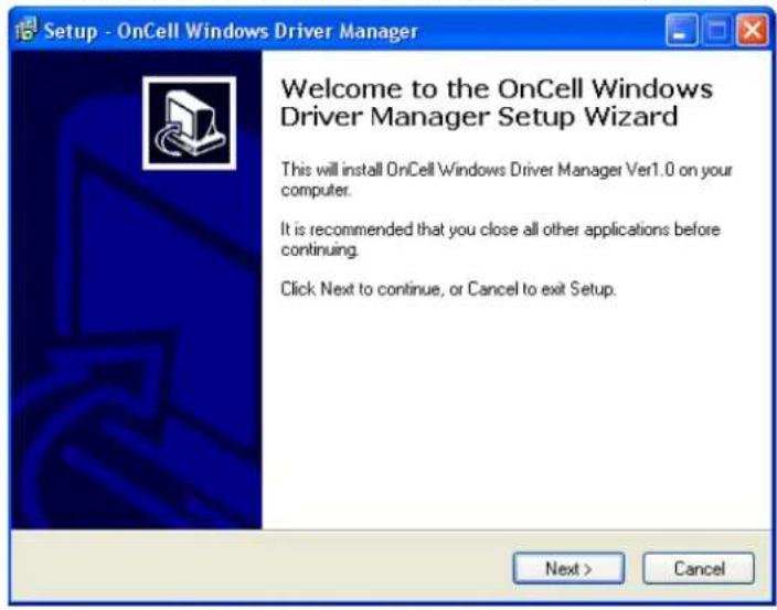
Click Next to install program files to the default directory, or click Browse to select an alternate location.
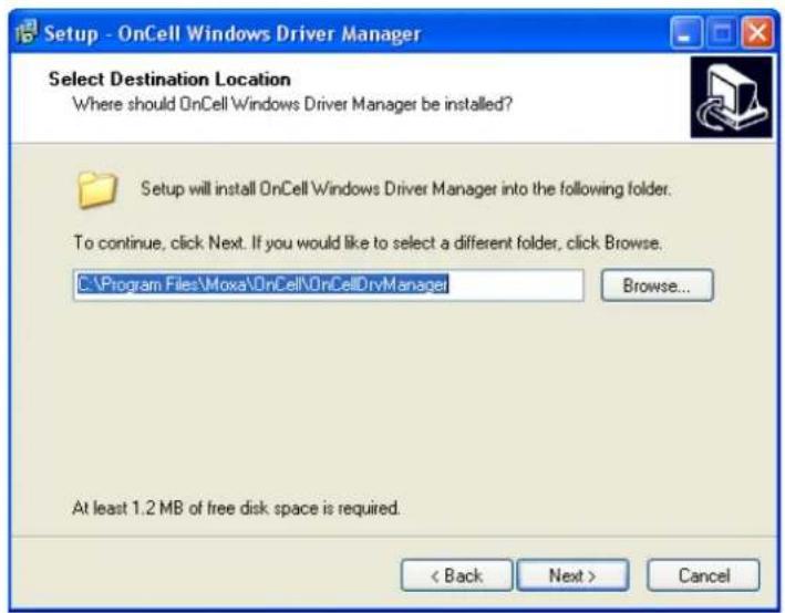
- Click Next to install the program's shortcuts in the appropriate Start Menu folder.
- Click Next to proceed with the installation. The installer then displays a summary of the installation options.
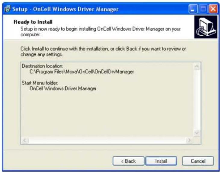
- Click Install to begin the installation. The setup window will report the progress of the installation. To change the installation settings, click Back and navigate to the previous screen. On Windows XP, the installer will display a message that the software has not passed Windows Logo testing. This is shown as follows:
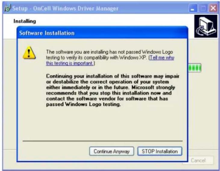
Click Continue Anyway to finish the installation.
- Click Finish to complete the installation of the Windows Driver Manager.
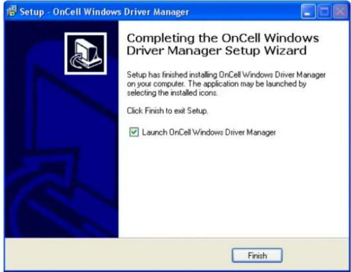
Using Windows Driver Manager
After you install Windows Driver Manager, you can set up the OnCell G3100's serial ports as remote COM ports for your PC host. Make sure that the serial port(s) on your OnCell G3100 are set to Real COM mode when mapping COM ports with Windows Driver Manager.
- Go to Start → Windows Driver Manager → Windows Driver Manager to start the COM mapping utility.
- Click the Add icon.
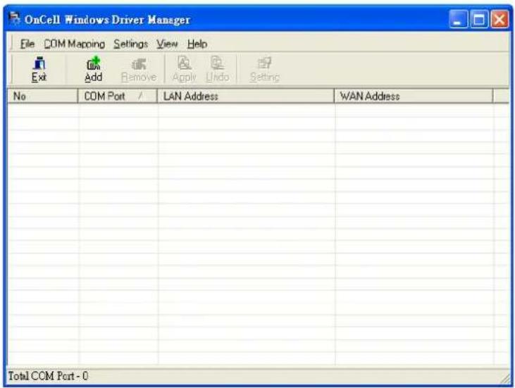
- Click Rescan to search for OnCell IP gateways. From the list that is generated, select the server that you will map COM ports to, and then click OK.
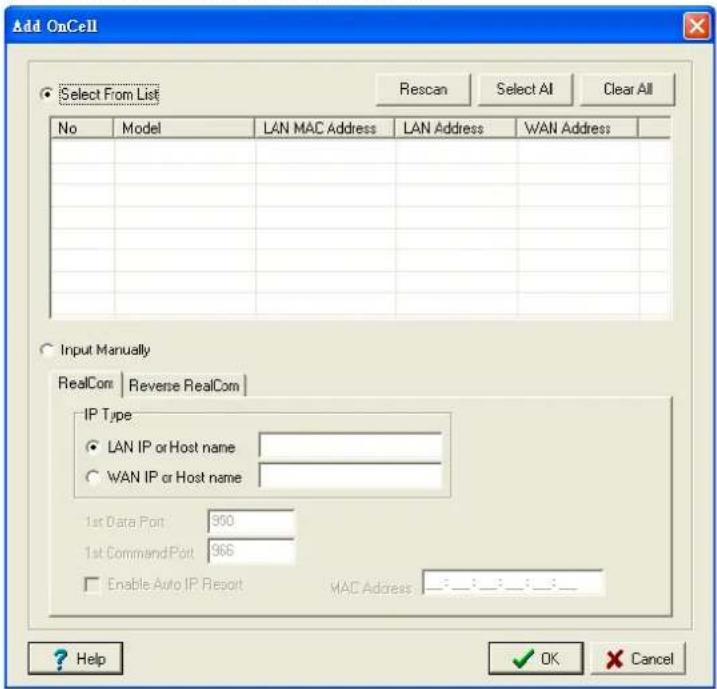
Alternatively, for Real COM mode, you can select Input Manually and then manually enter the OnCell G3100's IP Type. To do this, select LAN type, followed by 1st Data Port, and 1st Command Port for the COM ports that will be mapped to. Click OK to proceed to the next step. Note that the Add OnCell page supports FQDN (Fully Qualified Domain Name), in which case the IP address will be filled in automatically.
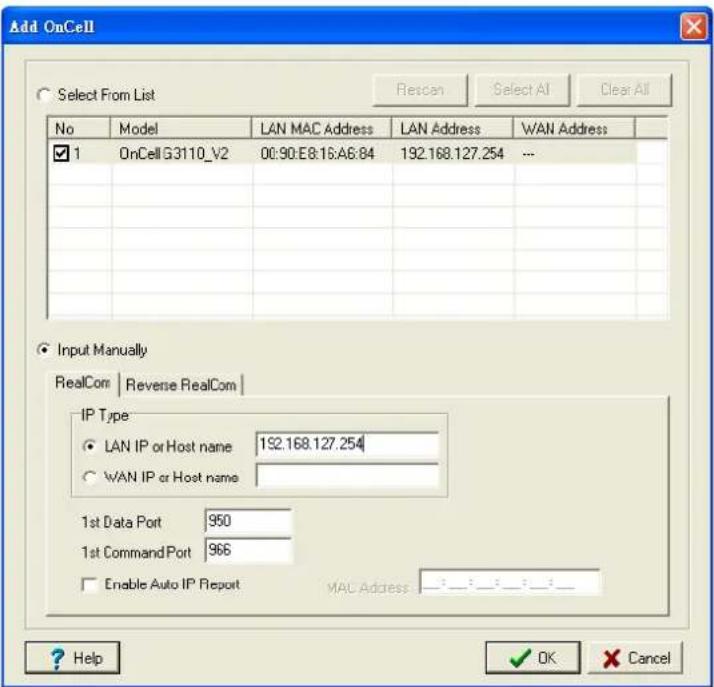
If you select "WAN IP or Host name," you must configure the 1st Data Port, 1st Command Port, and Total Ports for the COM ports that will be mapped to. Click OK to proceed to the next step. Note that the Add OnCell page supports FQDN (Fully Qualified Domain Name), in which case the IP address will be filled in automatically.
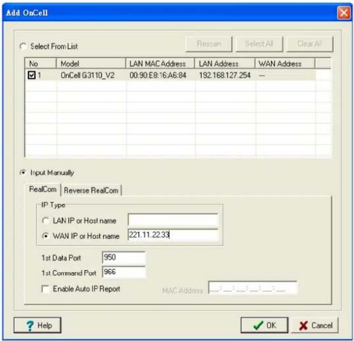
You can also select Enable Auto IP Report. Refer to the MAC address on the device lable and type in the MAC address in the MAC address line to update the IP address for this mapping entry automatically whenever the IP address of the OnCell G3100 is changed. For information on the Auto IP Report function, please refer chapter 6.
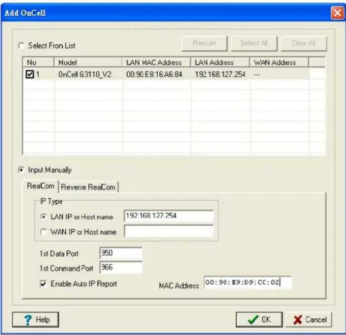
- COM ports and their mappings will appear in blue until they are activated. Activating the COM ports saves the information in the host system registry and makes the COM port available for use. The host computer will not have the ability to use the COM port until the COM ports are activated. Click Yes to activate the COM ports at this time, or click Cancel to activate the COM ports later.
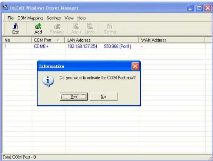
- When using Windows XP, a message is displayed during the activation of each port, indicating that the software has not passed Windows Logo certification. Click Continue Anyway to proceed.
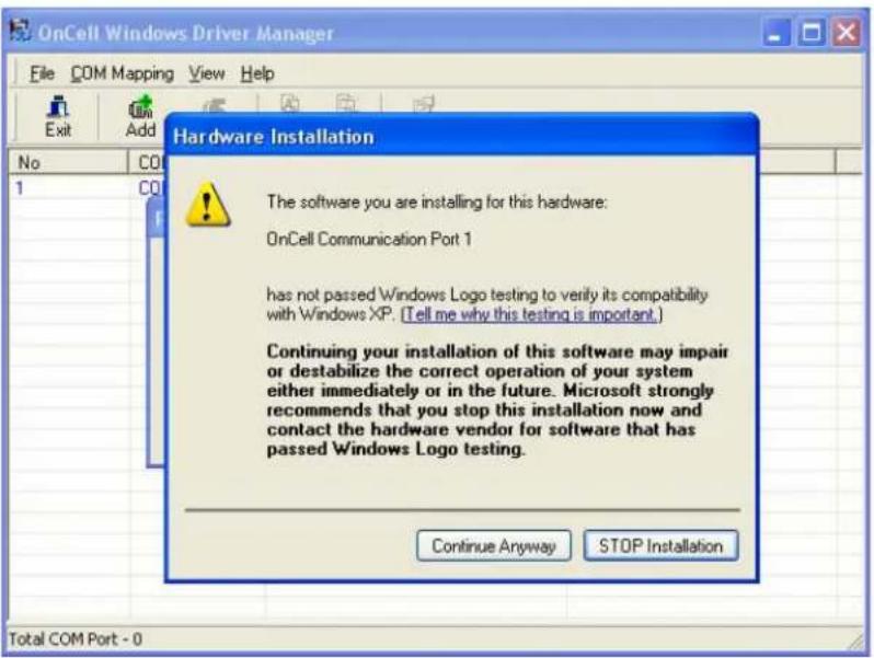
- Ports that have been activated will appear in black.
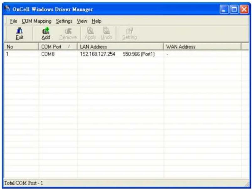
For Reverse Real COM mode, you can select Input Manually and then manually enter the LAN MAC address for OnCell G3100. Click OK to proceed to the next step.
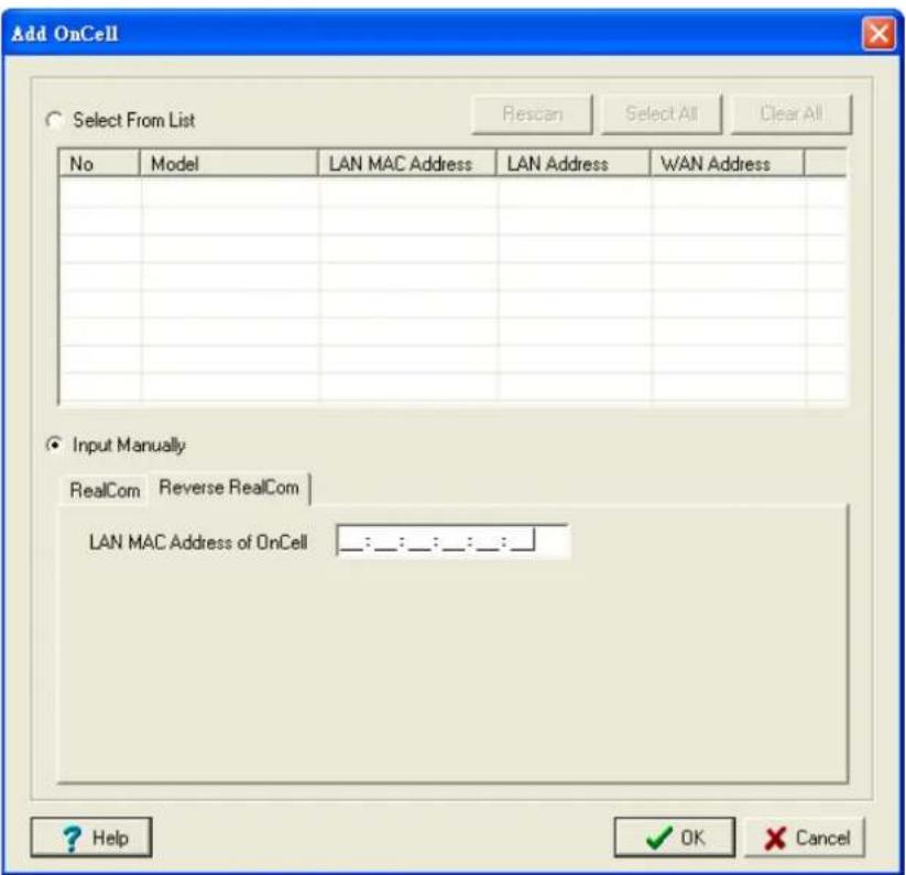
To re-configure the settings for a particular serial port on the OnCell G3100, select the row corresponding to the desired port, and then click the Setting icon.
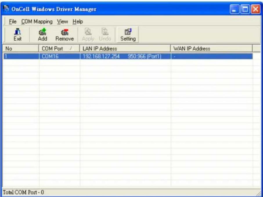
- On the Basic Setting page, use the COM Number drop-down list to select a COM number to be assigned to the OnCell G3100's serial port that is being configured. Note that ports that are "in use" will be labeled accordingly.
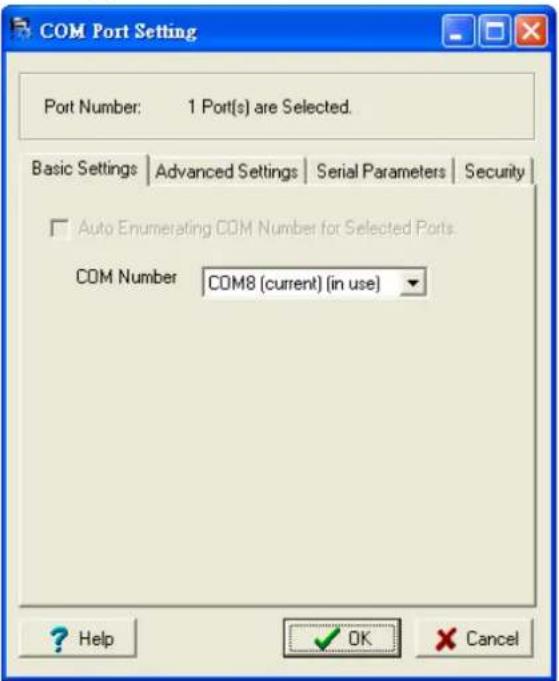
- Click the Advanced Setting tab to modify Tx Mode, FIFO, Fast Flush, and other parameters.
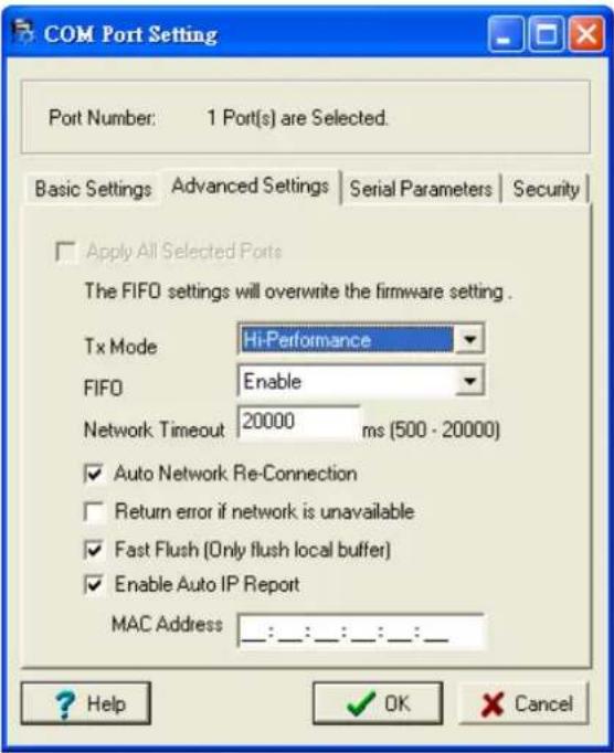
Tx Mode
Hi-Performance is the default for Tx mode. After the driver sends data to the OnCell G3100, the driver immediately issues a "Tx Empty" response to the program. Under Classical mode, the driver will not send the "Tx Empty" response until after confirmation is received from the OnCell G3100's serial port. This causes lower throughput. Classical mode is recommended if you want to ensure that all data is sent out before further processing.
FI FO
If FIFO is Disabled, the OnCell G3100 will transmit one byte each time the Tx FIFO becomes empty, and an Rx interrupt will be generated for each incoming byte. This will result in a faster response and lower throughput.
Network Timeout
You can use this option to prevent blocking if the target OnCell is unavailable.
Auto Network Re-Connection
With this option enabled, the driver will repeatedly attempt to re-establish the TCP connection if the OnCell G3100 does not respond to background "check alive" packets.
Return error if network is unavailable
If this option is disabled, the driver will not return any error even when a connection cannot be established to the OnCell G3100. With this option enabled, calling the Win32 Comm function will result in the error return code "STATUS_NETWORK_UNREACHABLE" when a connection cannot be established to the OnCell G3100. This usually means that your host's network connection is down, perhaps due to a cable being disconnected. However, if you can reach other network devices, it may be that the OnCell G3100 is not powered on or is disconnected. Note that Auto Network Re-Connection must be enabled in order to use this function.
Fast Flush (only flushes the local buffer)
For some applications, the user's program will use the Win32 "PurgeComm()" function before it reads or writes data. After a program uses this PurgeComm() function, the OnCell driver continues to query the OnCell's firmware several times to make sure no data is queued in the OnCell firmware buffer, rather than just flushing the local buffer. This design is used to satisfy some special considerations. However, it may take more time (about several hundred milliseconds) than a native COM1 due to the additional time spent communicating across the Ethernet. This is why PurgeComm() works significantly faster with native COM ports on the PC than with mapped COM ports on the OnCell G3100. In order to accommodate other applications that require a faster response time, the new OnCell driver implements a new Fast Flush option. By default, this function is enabled.
If you have disabled Fast Flush and find that COM ports mapped to the OnCell G3100 perform markedly slower than when using a native COM port, try to verify if "PurgeComm()" functions are used in your application. If so, try enabling the Fast Flush function and see if there is a significant improvement in performance.
Auto IP Report: When OnCell G3100 products are used in a dynamic IP environment, users must spend more time with IP management tasks. For example, if the OnCell works as a server (RealCom mode, TCP Server mode, or UDP mode), then the host, which acts as a client, must know the IP address of the server. If the DHCP server assigns a new IP address to OnCell, the host must have some way of determining OnCell's new IP address.
OnCell G3100 products help out by periodically reporting their IP address to the IP location server, in case the IP has changed. The parameters shown below are used to utilize the Auto IP report function. Once the Windows Driver Manager receives the Auto IP Report message, it will change the IP address of the COM mapping entry for the OnCell G3100 whose LAN MAC address is specified in the following MAC address field.
- The Serial Parameters tab in the following figure show the default settings when the OnCell G3100 is powered on. However, the program can redefine the serial parameters to different values after the program opens the port with Win32 API.
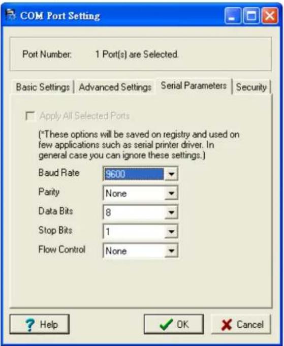
- Click the Security tab to configure security settings. Select the Enable Data Encryption option to enable data to be encrypted when transmitted over the COM ports. After selecting the encryption option, select the Keep connection option to start encrypting COM port communications immediately without restarting the COM ports. (If your application opens and closes COM ports frequently and the OnCell G3100 is only for one host, you can enable this option to speed up the opening/closing time. However, this will result in your host tying up the COM port so that other hosts cannot use it.) Select the Apply All Selected Ports option to enable the security settings to be applied to all COM ports.
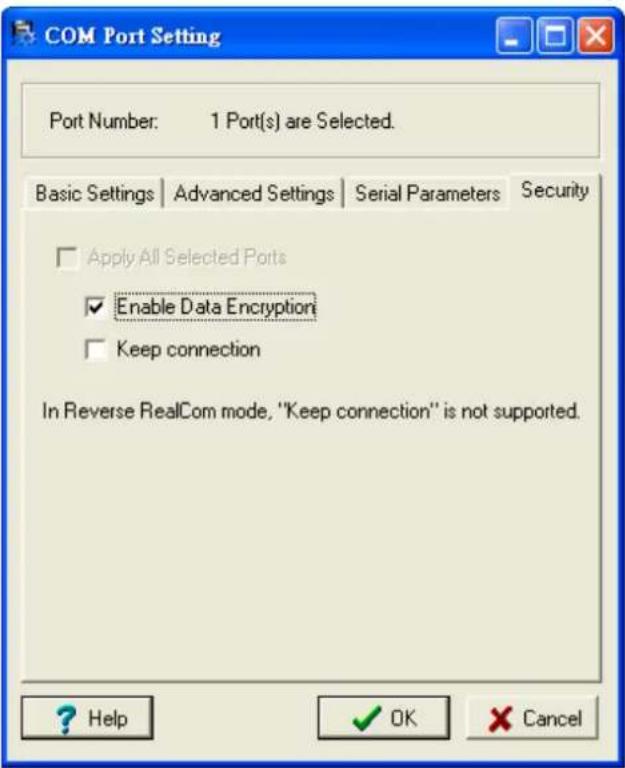
- To save the configuration to a text file, select Export from the COM Mapping menu. You will then be able to import this configuration file to another host and use the same COM Mapping settings in the other host.
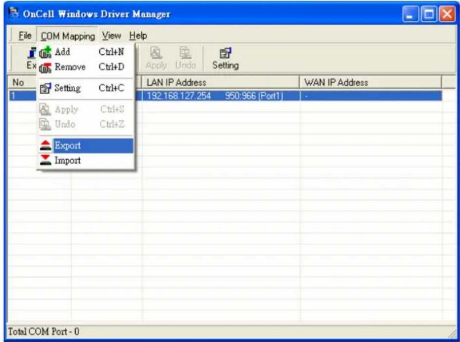
OnCell Search Utility
Installing OnCell Search Utility
- Download Windows Driver Manager from www.moxa.com, and then click the INSTALL COM Driver button to install the Windows Driver. Once the installation program starts running, click Yes to proceed.
- Click Next when the Welcome screen opens to proceed with the installation.
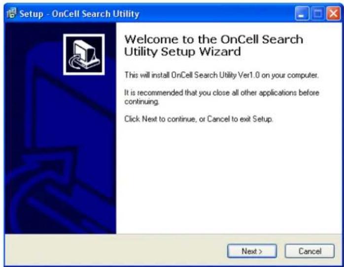
- Click Next to install program files to the default directory, or click Browse to select an alternate location.
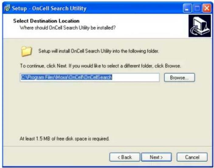
- Click Next to select additional tasks.
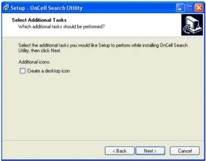
- Click Next to proceed with the installation. The installer then displays a summary of the installation options.
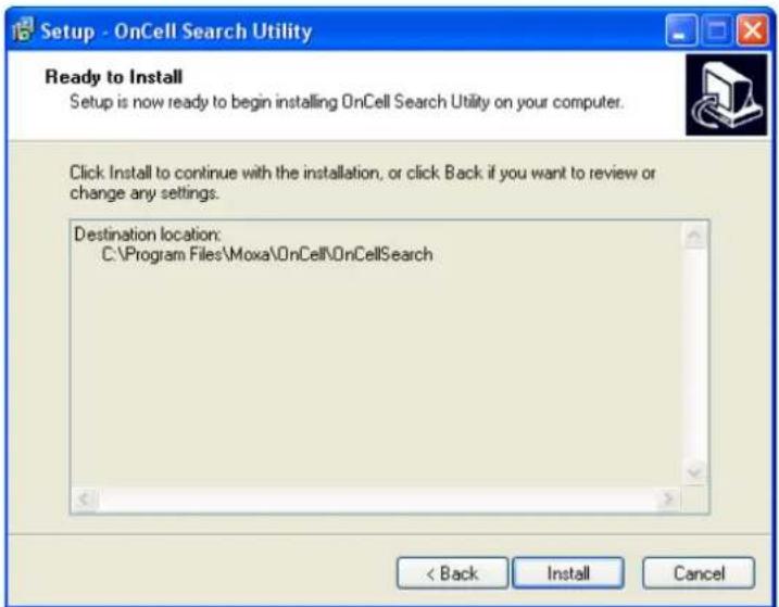
- Click Install to begin the installation. The setup window will report the progress of the installation. To change the installation settings, click Back and navigate to the previous screen.
- Click Finish to complete the installation of OnCell Search Utility.
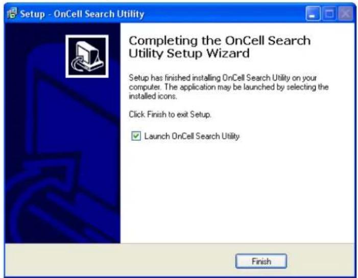
Configuring OnCell Search Utility
The Broadcast Search function is used to locate all OnCell G3100 servers that are connected to the same LAN as your computer. After locating an OnCell G3100, you will be able to change its IP address.
Since the Broadcast Search function searches by MAC address and not IP address, all OnCell G3100 servers connected to the LAN will be located, regardless of whether or not they are part of the same subnet as the host.
- Open OnCell Search Utility and then click the Search icon.
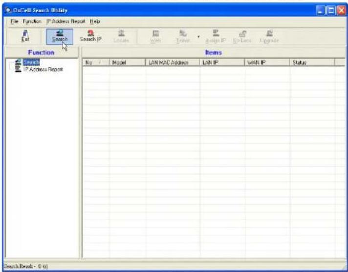
The Searching window indicates the progress of the search.
- When the search is complete, all OnCell G3100 servers that were located will be displayed in the OnCell Search Utility window.
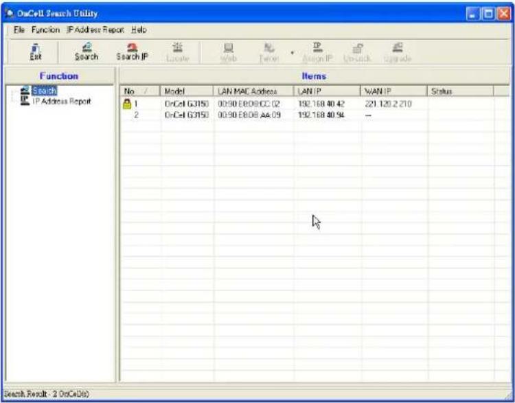
Click Locate to cause the selected device to beep.
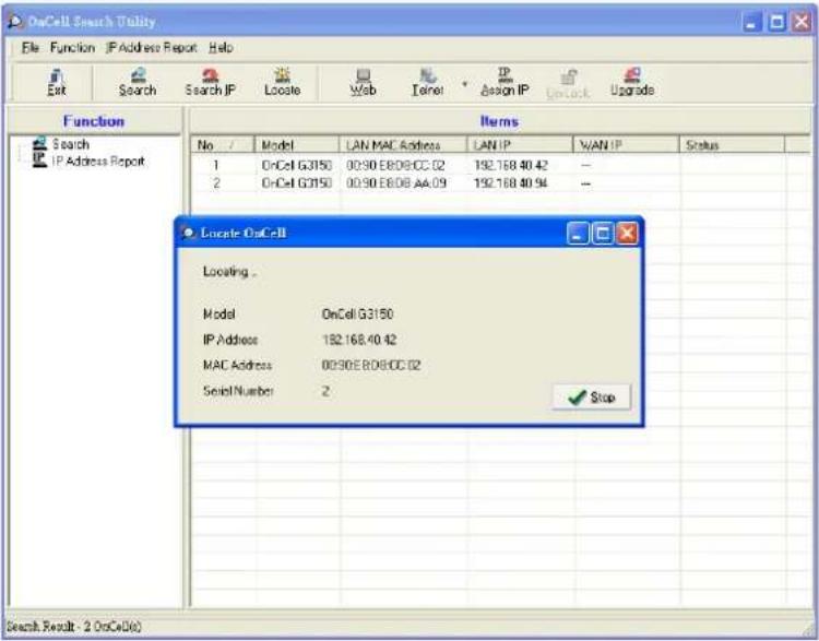
To modify the configuration of the highlighted OnCell G3100, click on the Console icon to open the web console. This will take you to the web console, where you can make all configuration changes. Please refer to Chapter 6, Using the Web Console, for information on how to use the web console.
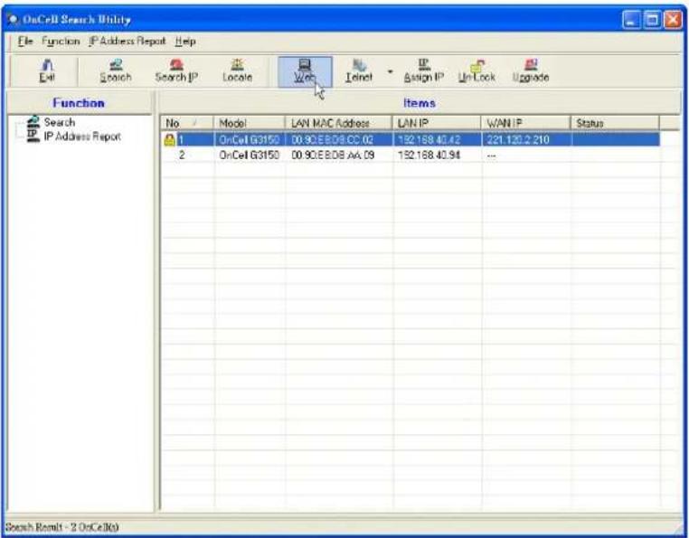
- Select IP Address Report for monitoring the status of IP Address, and click Go.
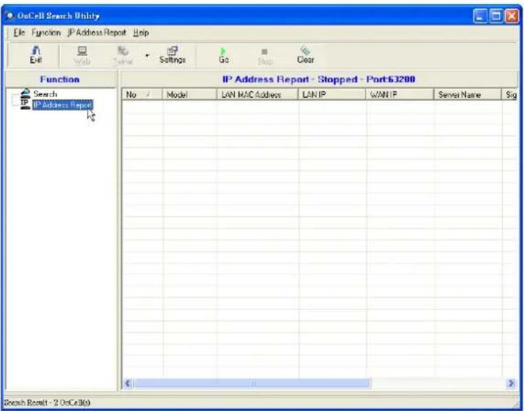
- To change the configuration of the IP Address Report, click on the Settings icon to open the IP Location Settings. The Local UDP listen Port number should match the web console Auto IP Report Settings' port number.
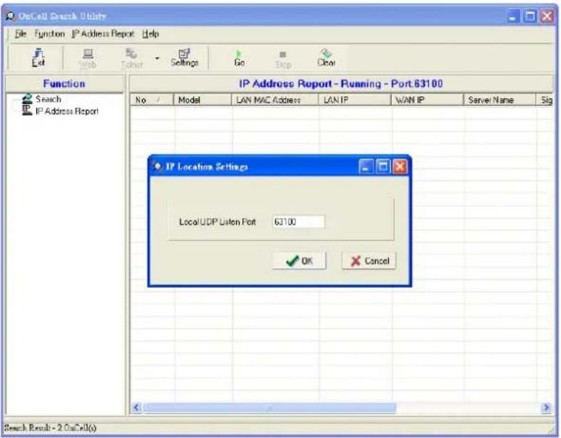
- Click the Go icon to complete the configuration. Please refer to Chapter 6, Using the Web Console, for information on how to use the IP Address Report.
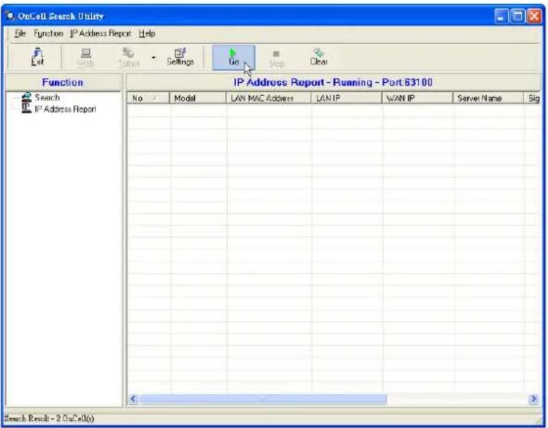
Moxa OnCell Linux Real TTY Driver
Basic Procedure
To map an OnCell G3100 serial port to a Linux host's tty port, follow these instructions:
- Set up the OnCell G3100. After verifying that the IP configuration works and you can access the OnCell G3100 (by using ping, telnet, etc.), configure the desired serial port on the OnCell G3100 to Real COM mode.
- Install the Linux Real TTY driver files on the host.
- Map the OnCell serial port to the host's tty port.
Hardware Setup
Before proceeding with the software installation, make sure you have completed the hardware installation. Note that the default IP address for the LAN interface of OnCell G3100 is 192.168.127.254.
NOTE After installing the hardware, you must configure the operation mode of the serial port on your OnCell G3100 to Real COM mode.
Installing Linux Real TTY Driver Files
- Obtain the driver file from the Moxa website, at http://www.moxa.com.
- Log in to the console as a super user (root).
- Execute cd / to go to the root directory.
- Copy the driver file moxa_oncell_realty.tgz to the / directory.
- Execute tar xvfz moxa_oncell_realty.tgz to extract all files into the system.
- Execute / tmp/ oncell_realty/ mxinst.
For RedHat AS/ES/WS and Fedora Core1, append an extra argument as follows:
# / tmp/ oncell_realty/ mxinst SP1
The shell script will install the driver files automatically.
- After installing the driver, you will be able to see several files in the /usr/lib/oncell_realty/driver folder:
mxaddsvr (Add Server, mapping tty port)
mxdelsvr (Delete Server, un-mapping tty port)
mxloadsvr (Reload Server)
mxmknod (Create device node/tty port)
mxrmnod (Remove device node/tty port)
mxuninst (Remove tty port and driver files)
At this point, you will be ready to map the OnCell serial port to the system tty port.
Mapping TTY Ports
Make sure that you set the operation mode of the desired OnCell G3100 serial port to Real COM mode. After logging in as a super user, enter the directory /usr/lib/oncell_realty/driver and then execute mxaddsvr to map the target OnCell serial port to the host tty ports. The syntax of mxaddsvr is as follows:
mxaddsvr [OnCell IP Address] [Total Ports] ([Data port] [Cmd port])
The mxaddsvr command performs the following actions:
- Modifies oncellreald.cf.
- Creates tty ports in directory /dev with major & minor number configured in oncellreald.cf.
- Restarts the driver.
Mapping tty ports automatically
To map tty ports automatically, you may execute mxaddsvr with just the IP address and number of ports, as in the following example:
<h1 id="cd-usrliboncell_realtydriver">cd /usr/lib/oncell_realty/driver</h1>
<h1 id="mxaddsvr-19216834-1">./mxaddsvr 192.168.3.4 1</h1>
In this example, one tty port will be added, with IP 192.168.3.4, with data port 950 and command port 966.
Mapping tty ports manually
To map tty ports manually, you may execute mxaddsvr and manually specify the data and command ports, as in the following example:
<h1 id="cd-usrliboncell_realtydriver-2">cd /usr/lib/oncell_realty/driver</h1>
<h1 id="mxaddsvr-19216834-1-4001-966">./mxaddsvr 192.168.3.4 1 4001 966</h1>
In this example, one tty port will be added, with IP 192.168.3.4, with data port 4001 and command port 966.
Removing Mapped TTY Ports
After logging in as root, enter the directory / usr/lib/oncell_realty/driver and then execute mxdelsvr to delete a server. The syntax of mxdelsvr is:
mxdelsvr [IP Address]
Example:
<h1 id="cd-usrliboncell_realtydriver-3">cd /usr/lib/oncell_realty/driver</h1>
<h1 id="mxdelsvr-19216834">./mxdelsvr 192.168.3.4</h1>
The following actions are performed when executing mxdelsvr:
- Modify oncellreald.cf.
- Remove the relevant tty ports in directory /dev.
- Restart the driver.
If the IP address is not provided in the command line, the program will list the installed servers and total ports on the screen. You will need to choose a server from the list for deletion.
Removing Linux Driver Files
A utility is included that will remove all driver files, mapped tty ports, and unload the driver. To do this, you only need to enter the directory / usr/ lib/ oncell_realty/ driver, then execute mxuninst to uninstall the driver. This program will perform the following actions:
- Unload the driver.
- Delete all files and directories in /usr/lib/moxa_oncell
- Delete directory / usr/lib/moxa_oncell
- Modify the system initializing script file.
Moxa OnCell UNIX Fixed TTY Driver
Installing the UNIX Driver
- Log in to UNIX and create a directory for the Moxa TTY. To create a directory named /usr/etc, execute the command:
<h1 id="mkdir-p-usretc">mkdir -p /usr/etc</h1>
- Copy moxa_oncell_fixedtty.tar to the directory you created. If you created the /usr/etc directory above, you would execute the following commands:
<h1 id="cp-moxa_oncell_fixedttytar-usretc">cp moxa_oncell_fixedtty.tar /usr/etc</h1>
<h1 id="cd-usretc">cd /usr/etc</h1>
- Extract the source files from the tar file by executing the command:
# tar xvf moxa_oncell_fixedtty.tar
The following files will be extracted:
README.TXT
oncellttyd.c --- source code
oncellttyd.cf --- an empty configuration file
Makefile --- makefile
VERSION.TXT --- fixed tty driver version
FAQ.TXT
- Compile and Link
For SCO UNIX:
# make sco
For UnixWare 7:
# make svr5
For UnixWare 2.1.x, SVR4.2:
# make svr42
Configuring the UNIX Driver
Modify the configuration:
The configuration used by the oncellttyd program is defined in the text file oncellttyd.cf, which is in the same directory that contains the program oncellttyd. You may use vi, or any text editor to modify the file, as follows:
ttyp1 192.168.1.1 950
For more configuration information, view the file oncellttyd.cf, which contains detailed descriptions of the various configuration parameters.
NOTE The "Device Name" depends on the OS. See the Device Naming Rule section in README.TXT for more information.
To start the oncellttyd daemon after system bootup, add an entry into /etc/inittab, with the tty name you configured in oncellttyd.cf, as in the following example:
ts:2:respawn:/usr/etc/oncell_fixedtty/oncellttyd -t 1
Device naming rule
For UnixWare 7, UnixWare 2.1.x, and SVR4.2, use:
pts/[n]
For all other UNIX operating systems, use:
ttyp[n]
Starting moxattyd
Execute the command init q or reboot your UNIX operating system.
Adding an additional server
- Modify the text file oncellttyd.cf to add an additional server. User may use vi or any text editor to modify the file. For more configuration information, look at the file oncellttyd.cf, which contains detailed descriptions of the various configuration parameters.
- Find the process ID (PID) of the program oncellttyd.
# ps -ef | grep oncellttyd
- Update configuration of oncellttyd program.
# kill -USR1 [PID]
(e.g., if oncellttyd PID = 404, kill -USR1 404)
This completes the process of adding an additional server.
The following topics are covered in this appendix:
□ Port Pinout Diagrams
RS-232 (male DB9) Pinouts
4W/2W RS-485/RS-422 (Terminal Block) Pinouts
Power Input and Relay Output Pinouts
□ Cable Wiring Diagrams
Serial Cables
➢ Pin Assignments for DB9 and DB25 Connectors
Port Pinout Diagrams
RS-232 (male DB9) Pinouts
| PIN | RS-232 |
| 1 | DCD |
| 2 | RXD |
| 3 | TXD |
| 4 | DTR |
| 5 | GND |
| 6 | DSR |
| 7 | RTS |
| 8 | CTS |
| 9 | --- |
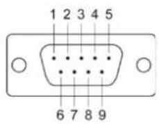
4W/2W RS-485/RS-422 (Terminal Block) Pinouts
| PIN | RS-422/ RS-485 (4W) | RS-485 (2W) |
| 1 TxD+(B) - | ||
| 2 TxD-(A) - | ||
| 3 RxD+(B) Data+ (B) | ||
| 4 | RxD-(A) | Data-(A) |
| 5 | GND GND | |
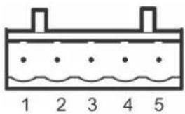
Power Input and Relay Output Pinouts
| PIN | Name | Function |
| 1 | V1+ DC Power Input 1 | |
| 2 | V1- | DC Power Input 1 |
| 3 | V2+ DC Power Input 2 | |
| 4 | V2- | DC Power Input 2 |
| 5 | Relay Output | |
| 6 | Relay Output | |
| 7 | I1 | Digital Input |
| 8 | COM_1 Digital Input GND | |
| 9 | I2 | Digital Input |
| 10 | COM_2 | Digital Input GND |
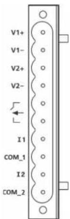
Cable Wiring Diagrams
Serial Cables
Female DB9 to Male DB9
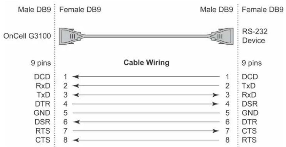
other
| OnCell G3100 | Cable Wiring | | ------------ | ----------- | | DCD | 1 | | RxD | 2 | | TxD | 3 | | DTR | 4 | | GND | 5 | | DSR | 6 | | RTS | 7 | | CTS | 8 |Female DB9 to Male DB25
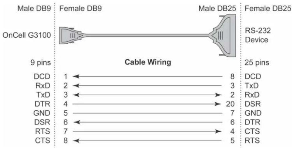
flowchart
graph LR
    A["OnCell G3100"] -->|9 pins| B["Cable Wiring"]
    B --> C["RS-232 Device"]
    B --> D["25 pins"]
    B --> E["8 pins"]
    B --> F["3 pins"]
    B --> G["20 pins"]
    B --> H["7 pins"]
    B --> I["6 pins"]
    B --> J["4 pins"]
    B --> K["5 pins"]
    B --> L["8 pins"]
    style A fill:#f9f,stroke:#333
    style B fill:#ccf,stroke:#333
Pin Assignments for DB9 and DB25 Connectors
Pin Assignments for DB9 Male and Female Connectors
DB9 Male Connector DB9 Female Connector
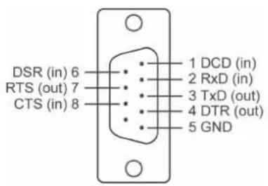
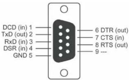
Pin Assignments for DB25 Male and Female Connectors
DB25 Male Connector
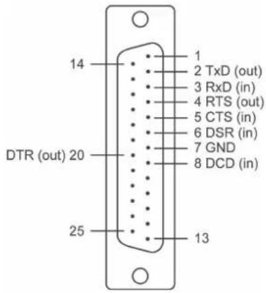
DB25 Female Connector
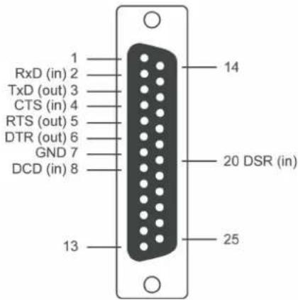
This appendix explains how to set up the environment to use RFC-2217 mode. RFC2217 defines general COM port control options based on the Telnet protocol and is used to allow the mapping of virtual COM ports to network ports. Any third party driver that supports RFC-2217 can be used to implement the virtual COM port on the OnCell G3100. The installation is as follows:
- In the OnCell G3100 console, set up the desired serial port's operation mode as RFC2217 mode. By default, the first serial port on the OnCell G3100 is assigned TCP port 4001, the second serial port is assigned TCP port 4002, and so on.
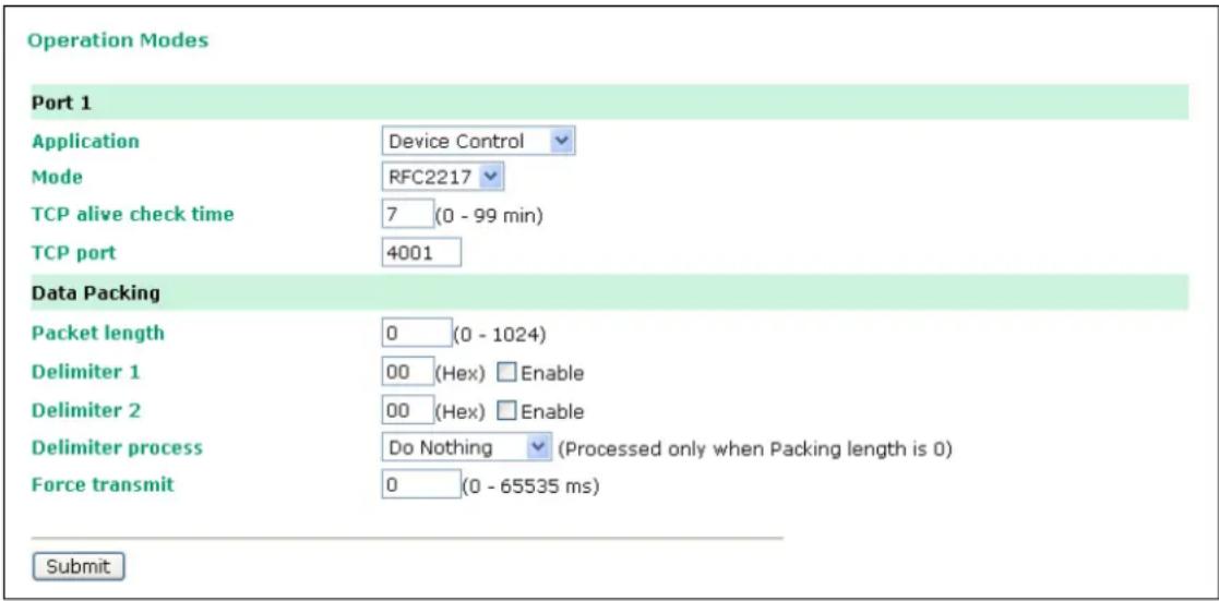
- Download and install a third party driver that supports RFC-2217, such as Serial/IP COM Port Redirector (from Tactical Software).
- Using your third party's configuration program, map a COM port to the OnCell G3100's IP address and the serial port's TCP port.
- Try opening the COM port that you just mapped. If you are able to open it, then the mapping was successful, and devices attached to the serial port on the OnCell G3100 may be treated as if they were attached directly to the host computer.
This appendix explains how to use the OnCell G3100 with DDNS. When the OnCell G3100 receive its IP address from a DHCP (Dynamic Host Configuration Protocol) server, remote servers will be unable to access it using a fixed IP address. With DDNS (Dynamic Domain Name Server), a remote server can access the OnCell G3100 using its domain name instead of its IP address.
Overview
The following is a summary of the process:
- The OnCell G3100 sends a request for an IP address to the DHCP server. At the same time, it notifies the DHCP server of its desired server name ("OC3100" in the illustration) according to the option 12 standard.
-
The DHCP server replies with the IP address that is assigned to the OnCell G3100, along with the domain name ("moxa.com" in the illustration) and the IP addresses for the DNS server and gateway.
-
If the OnCell G3100 has authorization to update the DNS server, it will register its FQDN (Fully Qualified Domain Name) with the DNS server. The OnCell G3100's FQDN will be in the format server name.domain name ("OC3100.moxa.com" in the illustration).
-
If the OnCell G3100 is not authorized to update the DNS server, the DHCP server can be used to update the DNS server. The DHCP server will register the DNS server with the PTR RR (the record of request for a domain name with IP address).
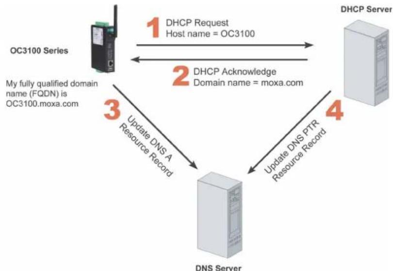
flowchart
graph TD
    A["OC3100 Series"] -->|1 DHCP Request Host name = OC3100| B["DHCP Server"]
    B -->|2 DHCP Acknowledge Domain name = moxa.com| A
    A -->|3 Update DNS A Resource Record| C["DNS Server"]
    C -->|4 Update DNS PTR Resource Record| B
    A -->|My fully qualified domain name (FQDN) is OC3100.moxa.com| C
![DHCP Scope [192.160.20.0] DN.moxa.com.tw Properties Action View Tree DHCP root-5g4g4knd Scope [192 Addres Addres Reserv Scope Server Opt General DNS Advanced You can set up the DHCP server to automatically update name and address information on DNS servers that support dynamic updates. ✓ Automatically update DHCP client information in DNS ● Update DNS only if DHCP client requests ○ Always update DNS □ Discard forward (name-to-address) lookups when lease expires ✓ Enable updates for DNS clients that do not support dynamic update Specifies whether the DHCP server sends dynamic updates to the DNS server for any DHCP clients that do not directly support performing these updates. If selected, clients running under corner versions of Windows are updated by the DHCP server for both their host (A) and pointer (PTR) resource records. By default, Windows 2008 DHCP clients are enabled to send dynamic updates to their configured DNS servers for their host (AI) resource records, but typically do not update pointer (PTR) resource records unless configured to do so. Configured in TCP/IP properties for a server. OK Cancel Apply](/content/2026/06/1160625/images/bdf8445ded7aec3e8729c900d7181024149d12c21011dafeee815df78f5cdbe5.jpg)
The above screenshot shows how DHCP can be set up to update the DNS.
Currently, the OnCell G3100 supports DNS service as provided by DynDNS. For detailed information on this option, please visit https://www.dyndns.com.
Configuration
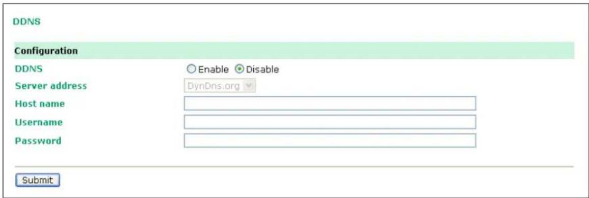
DDNS (default=Disable): Use this field to enable or disable DDNS.
Server address (default=DynDns.org): Currently, DynDns.org is the only option available for Server address.
Host name: In this field, use the name that you created on www.dyndns.com. The OnCell G3100 will update the DynDNS server with this host name.
Username: This is the user name used for update authentication.
Password: This is the password used for update authentication.
In this appendix, we provide a list of well known port numbers that may cause network problems if you set the OnCell G3100 to one of these ports. Refer to RFC 1700 for well known port numbers or to the following introduction from the IANA:
The port numbers are divided into three ranges: the Well Known Ports, the Registered Ports, and the Dynamic and/or Private Ports.
The Well Known Ports range from 0 through 1023.
The Registered Ports range from 1024 through 49151.
The Dynamic and/or Private Ports range from 49152 through 65535.
The Well Known Ports are assigned by the IANA, and on most systems, can only be used by system processes or by programs executed by privileged users. The following table shows famous port numbers among the listed well-known port numbers. For more details, please visit the IANA website at
http://www.iana.org/assignments/port-numbers.
| TCP Socket Application Service | |
| 0 Reserved | |
| 1 TCP Port Service Multiplexer | |
| 2 Management Utility | |
| 7 Echo | |
| 9 Discard | |
| 11 Active Users (systat) | |
| 13 Daytime | |
| 15 Netstat | |
| 20 FTP data port | |
| 21 FTP control port | |
| 23 Telnet | |
| 25 SMTP (Simple Mail Transfer Protocol) | |
| 37 Time (Time Server) | |
| 42 Host name server (names server) | |
| 43 Whois (nickname) | |
| 49 Login Host Protocol (login) | |
| 53 Domain Name Server (domain) | |
| 79 Finger protocol (finger) | |
| 80 World Wide Web (HTTP) | |
| 119 | Network News Transfer Protocol (NNTP) |
| 123 Network Time Protocol | |
| 213 IPX | |
| 160 to 223 Reserved for future use | |
| UDP Socket Application Service | |
| 0 Reserved | |
| 2 Management Utility | |
| 7 Echo | |
| 9 Discard | |
| 11 Active Users (systat) | |
| 13 Daytime | |
| 35 Any private printer server | |
| 39 Resource Location Protocol | |
| 42 Host name server (names server) | |
| 43 Whois (nickname) | |
| 49 Login Host Protocol (login) | |
| 53 Domain Name Server (domain) | |
| 69 Trivial Transfer Protocol (TETP) | |
| 70 Gopher Protocol | |
| 79 Finger Protocol | |
| 80 World Wide Web (HTTP) | |
| 107 Remote Telnet Service | |
| 111 Sun Remote Procedure Call (Sunrpc) | |
| 119 | Network News Transfer Protocol (NNTP) |
| 123 Network Time Protocol (NTP) | |
| 161 SNMP (Simp e Network Mail Protocol) | |
| 162 SNMP Traps | |
| 213 IPX (used for IP Tunneling) | |
OnCell Series provides several ways to configure Ethernet IP addresses. One of them is DHCP Client. When you set up the OnCell to use DHCP Client to configure Ethernet IP addresses, it will automatically send a DHCP request over the Ethernet to find the DHCP Server. And then the DHCP Server will send an available IP address to the OnCell. The OnCell will use this IP address for a period of time after receiving it. But the OnCell will send a DHCP request again to the DHCP Server. Once the DHCP Server realizes that this IP address is to be released to other DHCP Client, the OnCell then will receive a different IP address. For this reason, users sometimes find that the OnCell will use different IP addresses, not a fixed IP address.
In order to know what IP address the OnCell is using, you need to set up parameters in Network Settings via Web browser. The figure below is the OnCell Web console configuration window. Enter the IP address and the Port number of the PC that you want to send this information to.
Network Settings - Auto IP Report
Configuration
Auto IP report to host
Report to UDP port
Report period
Submit

ATTENTION
Search Utility and Driver Manager must be installed before using Auto IP report Format. Without Driver Manager, the Auto IP port cannot be opened.
Auto IP Report Format
| “Moxa”, 4 bytes | Info[0] | Info[1] | ... | Info[n] |
Info [n]
| Field ID Length Data | ||
| Length 1 1 Variable, Length is “Length Field” |
ID List
| ID Value | Description | Length | Note |
| 1 | Server Name | Variable | ASCII char |
| 2 | Hardware ID | 2 | Little-endian |
| 3 | MAC Address | 6 | 6 bytes MAC address. If the MAC address is "00-90-E8-01-02-03", the MAC[0] is 0, MAC[1] is 0x90(hex), MAC[2] is 0xE8(hex), and so on. |
| 4 | Serial Number | 4, DWORD | Little-endian |
| 5 | IP Address | 4, DWORD | Little-endian (LAN IP) |
| 9 | AP ID | 4, DWORD | Little-endian |
| 10 | IP Address2 | 4, DWORD | Little-endian (WAN IP) |
| 11 | Signal Level | 1 | Unsigned char |
| 12 RSSI 1 | Unsigned char |
Standard SMS can contain 160 characters. However, the characters typed must be part of the so-called 7-bit default alphabet as specified by GSM 3.38. As shown in the table below, this alphabet contains all ASCII characters and some accented characters.
For example, u umlaut (ü) and e with grave (è) are in this set. Using any character not in this set will force the SMS to be a Unicode SMS, in which case the length of the SMS will be limited to 70 characters.
Note that the following characters count as two characters: { } [ ] \~ | \ and the Euro symbol €. As you can see in the table below, this is because the codes for these characters must be prefaced by the escape code (0x1B).
The table below shows the 7-bit default alphabet as specified by GSM 03.38. The corresponding ISO-8859-1 decimal codes are shown in the rightmost column. Note that the euro sign (€) is also included.
| Hex | Dec | Character Name | Character | ISO-8859-1 DEC |
| 0x00 0 COMMERCIAL AT @ 64 | ||||
| 0x01 1 POUND SIGN £ 163 | ||||
| 0x02 2 DOLLAR SIGN $ 36 | ||||
| 0x03 | 3 | YEN SIGN | ¥ | 165 |
| 0x04 | 4 | LATIN SMALL LETTER E WITH GRAVE | € | 232 |
| 0x05 5 LATIN SMALL LETTER E WITH ACUTE | € | 233 | ||
| 0x06 6 LATIN SMALL LETTER U WITH GRAVE | ù | 249 | ||
| 0x07 7 LATIN SMALL LETTER I WITH GRAVE | ì | 236 | ||
| 0x08 8 LATIN SMALL LETTER O WITH GRAVE | ò | 242 | ||
| 0x09 | 9 | LATIN CAPITAL LETTER C WITH CEDILLA | Ç | 199 |
| 0x0A | 10 | LINE FEED | 10 | |
| 0x0B | 11 | LATIN CAPITAL LETTER O WITH STROKE | ∅ | 216 |
| 0x0C | 12 | LATIN SMALL LETTER O WITH STROKE | ∅ | 248 |
| 0x0D | 13 | CARRIAGE RETURN | 13 | |
| 0x0E | 14 | LATIN CAPITAL LETTER A WITH RING ABOVE | Å | 197 |
| 0x0F | 15 | LATIN SMALL LETTER A WITH RING ABOVE | Å | 229 |
| 0x10 | 16 | GREEK CAPITAL LETTER DELTA | Δ | |
| 0x11 | 17 | LOW LINE | - | 95 |
| 0x12 | 18 | GREEK CAPITAL LETTER PHI | Φ | |
| 0x13 | 19 | GREEK CAPITAL LETTER GAMMA | Γ | |
| 0x14 | 20 | GREEK CAPITAL LETTER LAMBDA | Λ | |
| 0x15 | 21 | GREEK CAPITAL LETTER OMEGA | Ω | |
| 0x16 | 22 | GREEK CAPITAL LETTER PI | II | |
| 0x17 | 23 | GREEK CAPITAL LETTER PSI | Ψ | |
| 0x18 | 24 | GREEK CAPITAL LETTER SIGMA | Σ | |
| 0x19 | 25 | GREEK CAPITAL LETTER THETA | Θ | |
| 0x20 | 26 | GREEK CAPITAL LETTER XI | Ξ | |
| 0x1B | 27 | ESCAPE TO EXTENSION TABLE | ||
| 0x1B0A | 27 10 | FORM FEED | 12 | |
| 0x1B14 | 27 20 | CIRCUMFLEX ACCENT | ^ | 94 |
| 0x1B28 | 27 40 | LEFT CURLY BRACKET | { | 123 |
| 0x1B29 | 27 41 | RIGHT CURLY BRACKET | } | 125 |
| 0x1B2F | 27 47 | REVERSE SOLIDUS (BACKSLASH) | \ | 92 |
| 0x1B3C | 27 60 | LEFT SQUARE BRACKET | [ | 91 |
| 0x1B3D | 27 61 | TILDE | ~ | 126 |
| 0x1B3E | 27 62 | RIGHT SQUARE BRACKET | ] | 93 |
| 0x1B40 | 27 64 | VERTICAL BAR | | | 124 |
| 0x1B65 | 27 101 | EURO SIGN | € | 164 (ISO-8859-15) |
| 0x1C | 28 | LATIN CAPITAL LETTER AE | Æ | 198 |
| 0x1D | 29 | LATIN SMALL LETTER AE | Æ | 230 |
| 0x1E | 30 | LATIN SMALL LETTER SHARP S (German) | ß | 223 |
| 0x1F | 31 | LATIN CAPITAL LETTER E WITH ACUTE | É | 201 |
| 0x20 | 32 | SPCE | 32 | |
| 0x21 | 33 | EXCLAMATION MARK | ! | 33 |
| 0x22 | 34 | QUOTATION MARK | " | 34 |
| 0x23 | 35 | NUMBER SIGN | # | 35 |
| 0x24 | 36 | CURRENCY SIGN | ¤ | 164 (ISO-8859-1) |
| 0x25 | 37 | PERCENT SIGN | % | 37 |
| 0x26 | 38 | AMPERSAND | & | 38 |
| 0x27 | 39 | APOSTROPHE | ' | 39 |
| 0x28 | 40 | LEFT PARENTHESIS | ( | 40 |
| 0x29 | 41 | RIGHT PARENTHESIS | ) | 41 |
| 0x2A | 42 | ASTERISK | * | 42 |
| 0x2B | 43 | PLUS SIGN | + | 43 |
| 0x2C | 44 | COMMA | , | 44 |
| 0x2D | 45 | HYPHEN-MINUS | - | 45 |
| 0x2E | 46 | FULL STOP | . | 46 |
| 0x2F | 47 | SOLIDUS (SLASH) | / | 47 |
| 0x30 | 48 | DIGIT ZERO | 0 | 48 |
| 0x31 | 49 | DIGIT ONE | 1 | 49 |
| 0x32 | 50 | DIGIT TWO | 2 | 50 |
| 0x33 | 51 | DIGIT THREE | 3 | 51 |
| 0x34 | 52 | DIGIT FOUR | 4 | 52 |
| 0x35 | 53 | DIGIT FIVE | 5 | 53 |
| 0x36 | 54 | DIGIT SIX | 6 | 54 |
| 0x37 | 55 | DIGIT SEVEN | 7 | 55 |
| 0x38 | 56 | DIGIT EIGHT | 8 | 56 |
| 0x39 | 57 | DIGIT NINE | 9 | 57 |
| 0x3A | 58 | COLON | : | 58 |
| 0x3B | 59 | SEMICOLON | : | 59 |
| 0x3C | 60 | LESS-THAN SIGN | < | 60 |
| 0x3D | 61 | EQUALS SIGN | = | 61 |
| 0x3E | 62 | GREATER-THAN SIGN | > | 62 |
| 0x3F | 63 | QUESTION MARK | ? | 63 |
| 0x40 | 64 | INVERTED EXCLAMATION MARK | i | 161 |
| 0x41 | 65 | LATIN CAPITAL LETTER A | A | 65 |
| 0x42 | 66 | LATIN CAPITAL LETTER B | B | 66 |
| 0x43 | 67 | LATIN CAPITAL LETTER C | C | 67 |
| 0x44 | 68 | LATIN CAPITAL LETTER D | D | 68 |
| 0x45 | 69 | LATIN CAPITAL LETTER E | E | 69 |
| 0x46 | 70 | LATIN CAPITAL LETTER F | F | 70 |
| 0x47 | 71 | LATIN CAPITAL LETTER G | G | 71 |
| 0x48 | 72 | LATIN CAPITAL LETTER H | H | 72 |
| 0x49 | 73 | LATIN CAPITAL LETTER I | I | 73 |
| 0x4A | 74 | LATIN CAPITAL LETTER J | J | 74 |
| 0x4B | 75 | LATIN CAPITAL LETTER K | K | 75 |
| 0x4C | 76 | LATIN CAPITAL LETTER L | L | 76 |
| 0x4D | 77 | LATIN CAPITAL LETTER M | M | 77 |
| 0x4E | 78 | LATIN CAPITAL LETTER N | N | 78 |
| 0x4F | 79 | LATIN CAPITAL LETTER O | O | 79 |
| 0x50 | 80 | LATIN CAPITAL LETTER P | P | 80 |
| 0x51 | 81 | LATIN CAPITAL LETTER Q | Q | 81 |
| 0x52 | 82 | LATIN CAPITAL LETTER R | R | 82 |
| 0x53 | 83 | LATIN CAPITAL LETTER S | S | 83 |
| 0x54 | 84 | LATIN CAPITAL LETTER T | T | 84 |
| 0x55 | 85 | LATIN CAPITAL LETTER U | U | 85 |
| 0x56 | 86 | LATIN CAPITAL LETTER V | V | 86 |
| 0x57 | 87 | LATIN CAPITAL LETTER W | W | 87 |
| 0x58 | 88 | LATIN CAPITAL LETTER X | X | 88 |
| 0x59 | 89 | LATIN CAPITAL LETTER Y | Y | 89 |
| 0x5A | 90 | LATIN CAPITAL LETTER Z | Z | 90 |
| 0x5B | 91 | LATIN CAPITAL LETTER A WITH DIAERESIS | Ä | 196 |
| 0x5C | 92 | LATIN CAPITAL LETTER O WITH DIAERESIS | Ö | 214 |
| 0x5D | 93 | LATIN CAPITAL LETTER N WITH TILDE | Ñ | 209 |
| 0x5E | 94 | LATIN CPAITAL LETTER U WITH DIAERESIS | Ü | 220 |
| 0x5F | 95 | SECTION SIGN | § | 167 |
| 0x60 | 96 | INVERTED QUESTION MARK | € | 191 |
| 0x61 | 97 | LATIN SMALL LETTER A | A | 97 |
| 0x62 | 98 | LATIN SMALL LETTER B | B | 98 |
| 0x63 | 99 | LATIN SMALL LETTER C | C | 99 |
| 0x64 | 100 | LATIN SMALL LETTER D | D | 100 |
| 0x65 | 101 | LATIN SMALL LETTER E | E | 101 |
| 0x66 | 102 | LATIN SMALL LETTER F | F | 102 |
| 0x67 | 103 | LATIN SMALL LETTER G | G | 103 |
| 0x68 | 104 | LATIN SMALL LETTER I | I | 104 |
| 0x69 | 105 | LATIN SMALL LETTER I | I | 105 |
| 0x6A | 106 | LATIN SMALL LETTER J | J | 106 |
| 0x6B | 107 | LATIN SMALL LETTER K | K | 107 |
| 0x6C | 108 | LATIN SMALL LETTER L | L | 108 |
| 0x6D | 109 | LATIN SMALL LETTER M | M | 109 |
| 0x6E | 110 | LATIN SMALL LETTER N | N | 110 |
| 0x6F | 111 | LATIN SMALL LETTER O | O | 111 |
| 0x70 | 112 | LATIN SMALL LETTER P | P | 112 |
| 0x71 | 113 | LATIN SMALL LETTER Q | Q | 113 |
| 0x72 | 114 | LATIN SMALL LETTER R | R | 114 |
| 0x73 | 115 | LATIN SMALL LETTER S | S | 115 |
| 0x74 | 116 | LATIN SMALL LETTER T | T | 116 |
| 0x75 | 117 | LATIN SMALL LETTER U | U | 117 |
| 0x76 | 118 | LATIN SMALL LETTER V | V | 118 |
| 0x77 | 119 | LATIN SMALL LETTER W | W | 119 |
| 0x78 | 120 | LATIN SMALL LETTER V | V | 120 |
| 0x79 | 121 | LATIN SMALL LETTER W | W | 121 |
| 0x7A | 122 | LATIN SMALL LETTER X | X | 122 |
| 0x7B | 123 | LATIN SMALL LETTER A WITH DIAERESIS | Ä | 228 |
| 0x7C | 124 | LATIN SMALL LETTER O WITH DIAERESIS | Ö | 246 |
| 0x7D | 125 | LATIN SMALL LETTER N WITH TILDE | Ñ | 241 |
| 0x7E | 126 | LATIN SMALL LETTER U WITH DIAERESIS | ü | 252 |
| 0x7F | 127 | LATIN SMALL LETTER A WITH GRAVE | à | 224 |
OnCell G3100 and OnCell Central Default Settings
| Setting Name Default Name | |
| Web Console Login | |
| Username Admin | |
| Password moxa | |
| Network Settings | |
| IP configuration Static | |
| IP address 192.168.127.254 | |
| Network 255.255.255.0 | |
| WINS function Enable | |
| LAN speed Auto | |
| GSM/ GPRS Settings | |
| Type GSM | |
| SIM PIN | |
| Band Auto | |
| GSM Operation Mode | |
| Modes PPP | |
| TCP/IP Compression Disable | |
| Inactivity Time 0 | |
| Link quality report | Disable |
| Connection Control | Always On/None |
| Connection Interval | 5 min |
| GPRS Operation Mode | |
| TCP/IP Compression Disable | |
| Inactivity Time 0 | |
| Link quality report | Disable |
| Connection Control | Always On/None |
| Connection Interval | 5 min |
| Real COM Mode | |
| Data port | 950 |
| Command port 966 | |
| TCP alive Check Time | 7 |
| Max connection | 1 |
| Ignore jammed IP | Disable |
| Allow driver control | Disable |
| Secure | Disable |
| Connection goes down | RTS/DTR always high |
| Packet length | 0 |
| Delimiter process | Do Nothing |
| Force transmit | 0 |
| Reverse Real COM Mode | |
| TCP port | 60950 |
| Command port 60966 | |
| Designated Port | 7010 to 7320 |
| TCP alive Check Time 7 | |
| Max connection 1 | |
| Ignore jammed IP Disable | |
| Allow driver control Disable | |
| Secure Disable | |
| Connection goes down RTS/DTR always high | |
| Packet length 0 | |
| Delimiter process Do Nothing | |
| Force transmit 0 | |
| TCP Server Mode | |
| TCP port 4001 | |
| Command port 966 | |
| TCP alive Check Time 7 | |
| Inactivity time 0 | |
| Ignore jammed IP Disable | |
| Allow driver control Disable | |
| Secure Disable | |
| Connection goes down RTS/DTR always high | |
| Packet length 0 | |
| Delimiter process Do Nothing | |
| Force transmit 0 | |
| TCP Client Mode | |
| TCP port 4001 | |
| Designated Port | 5010 to 5013 |
| TCP alive Check Time 7 | |
| Inactivity time 0 | |
| Ignore jammed IP Disable | |
| Secure Disable | |
| Connection control Stratup/None | |
| Packet length 0 | |
| Delimiter process Do Nothing | |
| Force transmit 0 | |
| Port Communication Parameters | |
| Baudrate 115200 | |
| Data bits | 8 |
| Stop bits | 1 |
| Parity | None |
| Flow control | RTS/CTS |
| FIFO | Enable |
| Interface | RS-232 |
| Port Data Buffering/ Log | |
| Port buffering (256K) | Disable |
| Serial data logging (256K) | Disable |
| SNMP Agent Setting | |
| SNMP | Enable |
| Read community String | Public |
| Write community String | Private |
| Console Settings | |
| HTTP console | Enable |
| HTTPS console | Enable |
| Telnet console | Enable |
| SSH console | Enable |
| Reset button Always Enable | |
| Virtual Server Settings | |
| Virtual Server Disable | |
| OnCell Central Server | |
| Server Disable | |
| Management information port 63201 | |
| Management configuration port 63202 | |
| Telnet port 63203 | |
| OP mode data port 1 63211 | |
| OP mode cmd port 1 63251 | |
| Service Forwarding | |
| Service forwarding Disable | |
| Service forwarding port 63204 | |
- OnCell G3100 Series User's Manual
- Copyright Notice
- Trademarks
- Disclaimer
- Technical Support Contact Information
- Moxa Americas
- Moxa Europe
- Moxa India
- Moxa China (Shanghai office)
- Moxa Asia-Pacific
- Getting Started 2-1
- Initial IP Address Configuration 3-1
- Introducing Serial Port Operation Modes 4-1
- Introducing OnCell Central Manager and Ethernet Operation Modes 5-1
- Using the Web Console.... 6-1
- Overview
- Package Checklist
- Standard Accessories
- Optional Accessories
- Product Features
- Product Specifications
- DoC (Declaration of Conformity)
- Federal Communication Commission Interference Statement
- OnCell G3100 Series Supporting Information
- FCC Radiation Exposure Statement
- □ Panel Layout
- □ Connecting the Hardware
- Panel Layout
- Connecting the Hardware
- Wiring Requirements
- ATTENTION
- Safety First!
- Wiring Caution!
- Temperature Caution!
- SIM Card Installation
- Connecting the Power
- Connecting the I/O Port
- Digital Input
- Connecting to the Network
- Connecting to a Serial Device
- Connecting to the Ethernet Device
- Adjustable Pull High/ Low Resistors for the RS-485 Port (for RS-232/ 422/ 485 models)
- LED Indicators
- GSM LED:
- GPRS LED:
- UMTS/ HSPA LED:
- Reset Button
- Static and Dynamic IP Addresses
- Factory Default IP Address
- Configuration Options
- OnCell Search Utility
- Web Console
- ARP
- Telnet Console
- Serial Console
- □ Device Control Applications
- □ Socket Applications
- ☐ Ethernet Modem Mode
- □ SMS Tunnel Mode
- □ Disabled Mode
- Device Control Applications
- Real COM and Secure Real COM Modes
- Types of Real COM Connection
- Fixed Public IP for OnCell
- Utilize Auto IP report
- Domain name with DDNS
- Reverse Real COM and Secure Reverse Real COM Modes
- Types of Reverse Real COM Connection
- Reverse RealCOM to PC's IP address
- Reverse RealCOM to PC's domain name
- RFC 2217 Mode
- Socket Applications
- TCP Server and Secure TCP Server Modes
- Types of TCP Server Connection
- Fixed Public IP for the OnCell
- Using Auto IP report
- Connecting TCP client and TCP server within the same cellular service provider
- TCP Client and Secure TCP Client Modes
- Types of TCP Client Connection
- TCP Client to PC's IP address
- TCP Client to PC's domain name
- UDP Mode
- Types of UDP Connection
- Fixed Public IPs for both OnCell and Host PC
- Ethernet Modem Mode
- SMS Tunnel Mode
- Disabled Mode
- Introducing OnCell Central Manager and Ethernet Operation Modes
- OnCell Central Management Software
- OnCell Central Serial Device Connection
- OnCell Central Ethernet Device Connection
- Cellular-Enabling Ethernet Device
- Virtual Modem Mode
- □ Using Your Web Browser
- □ Web Console Navigation
- □ Basic Settings
- □ Network Settings
- □ GuaranLink Settings
- Using Your Web Browser
- Browser Cookie Settings
- Trusted Site Settings
- Opening the Web Console
- Web Console Navigation
- Basic Settings
- Server Settings
- Time Settings
- Network Settings
- Basic Network Settings
- NOTE
- DNS Settings
- Advanced Network Settings
- Auto IP Report Settings
- GuaranLink Settings
- Background
- Common Settings
- GuaranLink Check Settings
- GSM GPRS Settings (For OnCell G3110 and G3150)
- Cellular Setting (OnCell G3110-HSPA and OnCell G3150-HSPA)
- GSM or GSM (CSD) Operation Mode
- GPRS or GPRS/ EDGE/ UMTS/ HSPA Operation Mode
- SMS Operation mode
- Virtual Modem Operation mode
- Port Setting Basics
- Real COM Mode
- Reverse Real COM Mode
- RFC2217 Mode
- TCP Server Mode
- Operation Modes
- TCP Client Mode
- Dial-in
- Dial-out
- Disconnection request from local site
- Disconnection request from remote site
- AT Commands
- Configuring the Cellular-Enabling Ethernet Device
- Host to OnCell via Cellular
- OnCell to Host via Cellular
- ☐ OnCell G3100 Web Settings
- □ CSD via AT command
- ☐ SMS via AT command
- □ GPRS via AT command
- ☐ GPRS via Windows Dial-up Network
- OnCell G3100 Web Settings
- Installing Windows Driver Manager
- Using Windows Driver Manager
- Using PComm for Data Transmission
- CSD via AT command
- Caller dialing out
- SMS via AT command
- GPRS via AT command
- GPRS via Windows Dial-up Network
- Click on Next.
- Select Connect to the Internet, and then click Next.
- What Are VPNs?
- OnCell VPN Specifications
- OnCell VPN Web Console Settings
- Manual Key/ ESP
- Configuration
- Remote Network
- Local Network
- Incoming Security Settings
- Outgoing Security Settings
- ISAKMP/PSK
- ISAKMP (Key Management)
- Local Identity
- ISAKMP phase 1
- ISAKMP phase 2
- Advanced settings
- Port Communication Parameters
- Serial Parameters
- Port Data Buffering/ Log
- Port Chipher Settings
- □ Misc. Network Settings
- □ Auto Warning Settings
- □ Maintenance
- □ Certificate
- □ System Monitoring
- □ System Status
- □ Network Status
- □ Save Configuration
- □ Restart
- Misc. Network Settings
- Accessible IP List
- To allow access to a specific IP address
- To allow access to hosts on a specific subnet
- To allow unrestricted access
- SNMP Agent Settings
- Read-only and Read/ Write Access Control
- DDNS
- Host Table
- System Log Settings
- Virtual Server Settings
- Auto Warning Settings
- Event Settings
- Serial Event Settings
- DCD changed
- DSR changed
- E-mail Alert
- SNMP Trap
- SMS Alert
- Customized SMS
- Remote Management
- Remote SMS Control
- Manual SMS
- Remote Caller ID
- Maintenance
- Console Settings
- Ping
- Firmware Upgrade
- Configuration Import/ Export
- Load Factory Defaults
- Change Password
- Certificate
- Ethernet SSL Certificate Import
- Certificate/ Key Delete
- System Monitoring
- Serial to Network Connections
- Serial Port Status
- Serial Port Error Count
- Serial Port Settings
- Chipher Usage Status
- System Status
- Serial Data Log
- System Log
- Dout State
- DIN and Power Status
- Network Status
- Network Connections
- Network Statistics
- Routing
- \* Client List
- Internet Sessions List
- Save Configuration
- Restart
- Restart System
- Restart Ports
- Select Ports
- Windows Driver Manager
- Tx Mode
- FI FO
- Network Timeout
- Auto Network Re-Connection
- Return error if network is unavailable
- Fast Flush (only flushes the local buffer)
- Installing OnCell Search Utility
- Configuring OnCell Search Utility
- Moxa OnCell Linux Real TTY Driver
- Basic Procedure
- Hardware Setup
- Installing Linux Real TTY Driver Files
- Mapping TTY Ports
- Mapping tty ports automatically
- Mapping tty ports manually
- Removing Mapped TTY Ports
- Removing Linux Driver Files
- Moxa OnCell UNIX Fixed TTY Driver
- Installing the UNIX Driver
- Configuring the UNIX Driver
- Modify the configuration:
- Device naming rule
- Starting moxattyd
- Adding an additional server
- □ Port Pinout Diagrams
- □ Cable Wiring Diagrams
- Port Pinout Diagrams
- RS-232 (male DB9) Pinouts
- 4W/2W RS-485/RS-422 (Terminal Block) Pinouts
- Power Input and Relay Output Pinouts
- Cable Wiring Diagrams
- Serial Cables
- Pin Assignments for DB9 and DB25 Connectors
- Pin Assignments for DB9 Male and Female Connectors
- Pin Assignments for DB25 Male and Female Connectors
Brand : Moxa
Model : OnCell G3150-T
Category : Uncategorized