
Ei414RF - Alarm Ei Electronics - Free user manual and instructions
Find the device manual for free Ei414RF Ei Electronics in PDF.


| Product Type | Fire / CO Alarm Interface |
| Brand | Ei Electronics |
| Model | Ei414RF |
| Power Supply | 230VAC (50Hz) or 11-30VDC |
| Backup Battery | Internal 3V Lithium (non-replaceable) |
| Relay Outputs | 3 relays (Fire, CO, Service) – NO/NC contacts, rated 250VAC @ 5A resistive |
| RF Frequency | 868.499 MHz |
| RF Range | Over 100 meters in free space |
| Dimensions | 185 x 90 x 37 mm |
| Weight | 300 g |
| Mounting | Wall mount or 35mm DIN rail (clips not included) |
| Operating Temperature | 0°C to 40°C |
| Storage Temperature | 0°C to 35°C (dry area) |
| Humidity Range | 15% to 95% RH (non-condensing) |
| Guarantee | 5 years |
| Compliance | CE (Directive 1999/5/EC) |
| LED Indicators | Power (green), RF activity (blue), Fire (red), CO (red), Service (red) |
| Key Feature | RadioLINK wireless interconnection |
| Key Feature | House coding for system security |
| Key Feature | Test mode for installer verification |
| Key Feature | Service relay for system faults |
| Key Feature | Delayed transmission option (selectable via DIP switch) |
Frequently Asked Questions - Ei414RF Ei Electronics
User questions about Ei414RF Ei Electronics
0 question about this device. Answer the ones you know or ask your own.
Ask a new question about this device
Download the instructions for your Alarm in PDF format for free! Find your manual Ei414RF - Ei Electronics and take your electronic device back in hand. On this page are published all the documents necessary for the use of your device. Ei414RF by Ei Electronics.
USER MANUAL Ei414RF Ei Electronics
Fire / CO Alarm Interface

Model: Ei414

Electronics®
fire + gas detection
Instruction Manual
Read and retain carefully for as long as the product is being used. It contains vital information on the operation and installation of your Fire / CO Alarm Interface. The booklet should be regarded as part of the product.
If you are just installing the unit, the booklet must be given to the householder. The booklet is to be given to any subsequent user.
Contents
- Introduction & Connection Diagrams ...... 3 Page
- Typical Installation Examples 8
- Installation 11
- House Coding 18
- Testing 22
- Service Relay 23
- User Information 24
- Troubleshooting the RadioLINK 26
- Technical Specification 27
- Service & Guarantee 28
- Contact Us 32
1. Introduction
The Ei414 Fire / CO Alarm Interface can be used to connect Ei Electronics RadioLINK Alarm Systems to suitable other Systems such as Fire Panels, Telecare Systems, Auto Diallers, Security Systems etc. The Ei414 has 3 output relays for Fire, CO & Service that can be triggered by an Ei Electronics RF Alarm System. These relays can be directly connected to the other Systems or alternatively can be used to trigger one of the other Systems RF transmitters. A RadioLINK system consists of Ei Electronics RadioLINK Smoke, Heat and CO Alarms along with RadioLINK accessory devices that are interconnected using the Ei Electronics proprietary RF protocol system. The Ei414 must be House Coded to the other RadioLINK devices in the system.
Wireless Smoke Alarm System Wireless

RF Smoke Alarm

RF Smoke Alarm

RF Smoke Alarm

Alarm Controller
Alarm Interface Alarm Interface
bke &
Carbon Monoxide Alarm System

RF CO Alarm

RF Smoke Alarm

RF Smoke Alarm

Alarm Controller

| Model No. - Alarms Comment | |
| Ei140RC, Ei160RC & Ei2110 Series Smoke Alarms | The Alarms must be fitted on Ei168RC RadioLINK bases |
| Ei262 Mains Carbon Monoxide Alarms The Ei262 has built-in RadioLINK technology | |
| Ei605 & Ei650 Series Smoke Alarms Alarms must be fitted with the correct Ei605 & Ei650 series RadioLINK module | |
| Ei208W powered for life Carbon Monoxide Alarms | The Alarms must be fitted with Ei200MRF RadioLINK modules |
| Ei170RF & other RadioLINK devices Contact us or visit our website for details | |
Due to our continuous improvements policy, product performance and features are being frequently updated - See Contact Us section
Hardwired Output Connection Diagram
![graph TD A["External Panel* (Fire / Telecare etc.)"] --> B["FIRE"] A --> C["SERVICE"] A --> D["CO"] B --> E["C"] B --> F["NO"] B --> G["NC"] C --> H["C"] C --> I["NO"] C --> J["NC"] D --> K["C"] D --> L["NO"] D --> M["NC"] E --> N["Ei208WRF / Ei650RF / Ei168RC / E i262 / Ei450"] F --> N G --> N H --…](/content/2026/06/1160588/images/8adcbd6080dd972ee09e528b2e1e1c2c2760a87bb08c09366bd706efddd26366.jpg)
* For connection to External Panel see Manufacturers instructions
Wireless (RF) Connection Output Diagram
![graph TD A["External RF Panel (Fire / Telecare etc.)"] --> B["RF Transmitter"] B --> C["FIRE"] C --> D["C"] C --> E["NO"] C --> F["NC"] G["RF Signal Input from Ei Alarm System"] --> H["Service"] H --> I["C"] H --> J["NO"] H --> K["NC"] L["External RF Panel"] --> M["RF Transmitter"] M --> N["CO"] N -…](/content/2026/06/1160588/images/5b0d997312f73e06d67ec1a0b59edf25e97d3d657f16170e2dbb793b79fc698b.jpg)
Input Connection Diagram
![graph TD A["External Device\n(Strobe etc.)"] -->|FIRE| B["C"] A -->|C| C["NO"] A -->|NC| D["NC"] A -->|C| E["NO"] A -->|C| F["NC"] A -->|C| G["NO"] A -->|C| H["NC"] B --> I["RF Fire Signal Output"] C --> I D --> I E --> I F --> I G --> I H --> I I --> J["Ei414"] J --> K["230VAC"] K --> L["External D…](/content/2026/06/1160588/images/9f1b16eabd61a177291df8614e280e6bee8655361e217a7c0d7ca07378de842e.jpg)
* For connection to External Devices see Manufacturers instructions
2. Typical Installation Examples
RadioLINK Mains Powered Alarm System
External Panel (Fire / Telecare etc.)

Ei166RC Smoke Alarm with Ei168RC RadioLINK Base
Ei164RC Heat Alarm with Ei168RC RadioLINK Base

Ei450 Alarm Controller

Ei414
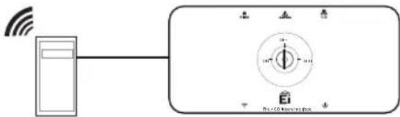
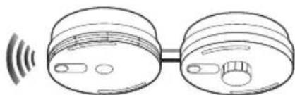
In the event of a fire, the Ei161RC / Ei166RC / Ei164RC will detect Smoke / Heat and the Ei168RC base will transmit an RF fire signal to the Ei414. The Ei414 will then trigger the external panel.
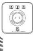
N.B. The Ei450 Alarm Controller MUST be used to test the RadioLINK Alarm System (at least 1 x Ei168RC must be fitted - see 'User Information' section).
RadioLINK Battery Powered Alarm System
External RF Panel
(Fire / Telecare etc.)

Ei650RF
Smoke Alarm

Ei603TYCRF
Heat Alarm

Ei450 Alarm
Controller
RF Transmitter
Ei414
In the event of a fire, the Ei650RF / Ei603TYCRF will detect Smoke / Heat and transmit an RF fire signal to the Ei414. The Ei414 will then trigger the RF transmitter and alert the external panel.
RadioLINK / Hard Wired Hybrid System
External RF Panel
(Fire / Telecare etc.)

Ei650RF
Smoke Alarm

Ei208WRF
Carbon Monoxide
Alarm
Ei450 Alarm
Controller
![graph LR A["fire"] --> B["CO"] B --> C["Ei414"]](/content/2026/06/1160588/images/0fd1c04fc8a5ed244b5a787cda00d5dc094796973e41e32e0d8f91c2073a49f4.jpg)
RF Transmitters
Ei166RC
Smoke Alarm with Ei168RC
RadioLINK Base
In the event of a fire / CO event, the relevant Smoke / Heat / CO Alarm will transmit an RF signal to the Ei414. The Ei414 will then trigger the relevant RF transmitter and alert the external panel.
- Installation


Note: This MUST be switched to the
'ON' position upon installation (see 'Installation' section)
(N.B. The Lithium battery is not replaceable)
Mounting and Wiring
AC Mains Wiring (230V)
Warning: To prevent injury, this apparatus must be securely attached to the wall in accordance with the installation instructions.
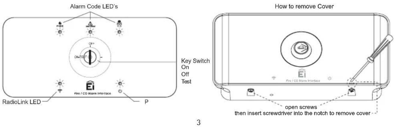
- Remove the cover (see page 3). Mount the Ei414 in a suitable location on a wall using the fixings provided, away from any objects that may block the RF signal (i.e away from metal surfaces). The Ei414 may also be mounted on a 35mm Din Rail. Mounting clips for this application must be purchased separately.
- Disconnect the AC mains supply from the circuit that is going to be used. The disconnect device (i.e mains switch) must be an all pole circuit breaker, with a contact gap of minimum 3mm and disconnects both poles simultaneously.
- The house wiring must be connected to the terminal block on the unit:
L: Live – connect to the house wires coloured brown or marked L
N: Neutral - connect to the house wires coloured blue or marked N
E: Earth – connect to yellow/green wires or marked E
Note: Wiring must be installed in compliance with local regulations and by qualified/competent personnel.
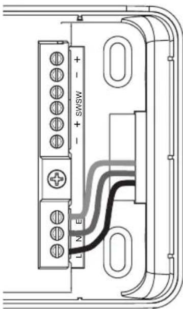
Front View: standard wiring from wall mount
(See adjacent diagram for wiring option using surface trunking and knockout segments on the back of the base. Remove segments using a pliers or similar).
- The green LED will indicate if power has been connected.
- Ensure the Dip Switch has been set to the correct orientation (see 'Dip Switch Operation section').
- Important: The backup battery switch must be switched on.
- If using an RF Transmitter connect as advised by the manufacturer to the relevant relay. Use the knockout segments on the back of the base. Remove segments using a pliers or similar (See diagrams on page 15).
- Fit and secure the top cover with the screws provided. (see page 3).
- Insert and turn the key supplied to the 'TEST' position to begin system testing (see 'TESTING' section).
For a 11-30V DC external source
- The Ei414 should be located next to DC external source.
- Locate the auxiliary power output in the DC external source and wire it to the DC Power Input connector on the Ei414.
- Check that the polarity of the auxiliary power supply has been wired correctly and the power LED is on.
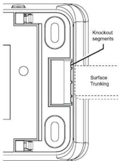
Rear View: optional wiring using surface trunking
-
The trigger input voltage signal is optional and can be triggered by either a 12-24V DC power supply or alternatively from a dry contact signal.
-
Repeat steps 5 to 9 as above.
Caution - Alternative Energy Sources - (wind, solar, UPS etc.)
This product is designed to be connected to a True Sine Wave 230VAC supply. If connecting to a power source that utilises an inverter, e.g. PV solar panel, the Total Harmonic Distortion (THD) must be less than 5%. If in doubt please check with the manufacturer of the inverter. This also applies to battery powered UPS (Uninterruptible Power Supply) inverters or Light Dimmer Circuits. The Ei414 must not be connected when the house wiring
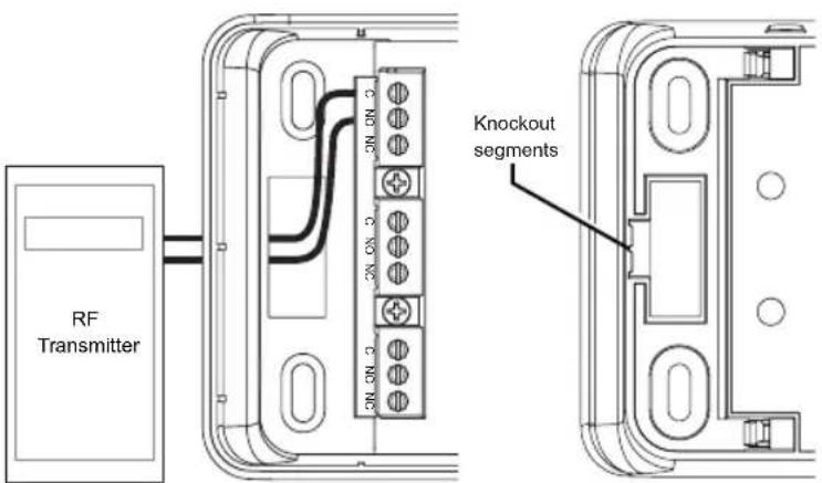
Front View: RF Transmitter installation
Rear View: Knockout segments
insulation is being checked with high voltages, i.e. do not use a high voltage insulation tester on the unit. The unit must not be exposed to dripping or splashing.
DIP Switch Operation (for delayed transmission)
The Ei414 contains a dip switch which specifies whether the device will work in continuous mode or through a pulsed operation. It is also used to delay the output action.


Normal operation mode (default) - continuous operation, no delay Switch 1 & 2 in the '1 & 2' position
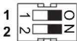
Pulsed Operation – Relay fires for 4 seconds, no delay Switch 1 & 2 in the 'ON' position

10 Sec delay – Relays fire 10 secs after it receives message. If a cancel message is received within this period, the relevant relay won't activate Switch 1 in the 'O' position & switch 2 in the '2' position

30 Sec delay – Relays fire 30 secs after it receives message. If a cancel message is received within this period, the relevant relay won't activate Switch 1 in the '1' position & switch 2 in the 'N' position
Please note: The dip switch only applies to the Fire and CO relays, it does not apply to the Service relay.
Keyswitch Orientations
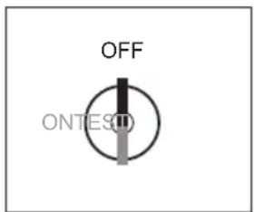
The Ei414 will be shipped in the 'OFF' position.
When in the 'OFF' position the Ei414 does not respond to any RF signals.

In the 'ON' position the Ei414 responds to a fire alarm signal (activates the fire relay) or to a CO alarm signal (activates the CO relay).
It will not respond to a button test signal.
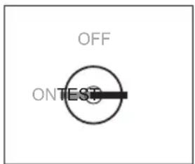
In the 'TEST' position the Ei414 responds to a button test signal (will activate the fire or the CO relay depending on the unit that was button tested).
N.B. When testing the system with an Ei450 Alarm Controller, only the fire relay will activate.
4. House Coding
It is essential to House Code the Ei414 to all the other RadioLINK Alarms and devices in the system to ensure they will not communicate with nearby systems. Failure to House Code the system may also result in a system malfunction.

To House Code:
Using a small screwdriver press and hold the House Code button on the bottom of the Ei414 then release. The RadioLINK blue LED will light up and then flash rapidly for a moment.

House Code all other RadioLINK Alarms and devices in the system. Consult the instruction manuals on how to House Code the Alarms and devices. It is essential that each individual Alarm / device is put into House Code mode in its actual location.

Return to the Ei414 and check that RadioLINK LED is flashing blue. The number of flashes should equal the number of RadioLINK Alarms and devices in the system. A system with 2 x Smoke Alarms, 1 x CO Alarm, 1 x Alarm Controller and 1 x Ei414 will result in 5 blue flashes. It may take up to 10 minutes before all 5 flashes are seen.
The flash pattern will repeat every 5 to 10 seconds while the Ei414 remains in House Code.
If it fails to flash the correct number of times, then consult the 'Troubleshooting' section of this instruction manual.

Now, walk around the house to verify that all the other RadioLINK Alarms and devices are giving the correct amount of flashes.
If any of these fail to flash the correct number of times, then consult the 'Troubleshooting' section of this instruction manual.
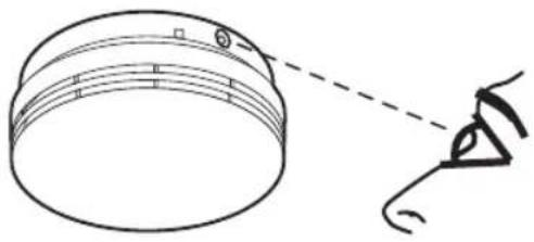
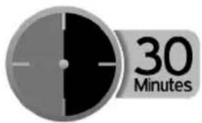
To complete the commissioning, the system must exit House Code mode. The units will automatically exit House Code after 30 minutes. Once coded the system will not communicate with any other RadioLINK Alarms and devices outside the House Coded group.
To manually exit House Code press the House Code button on the Ei414. When the RadioLINK LED lights up blue, release the button. This unit will then send an exit House Code signal to all the other RadioLINK Alarms and devices to exit House Code.
After a short period the blue light will turn off and the system will return to standby mode (normal). Depending on the number of RadioLINK Alarms and devices in the system this period could vary from 5 to 20 seconds.

Reset the House Code
Sometimes in order to resolve an RF communication issue, e.g. Alarms have to be relocated, it may be necessary to reset and House Code all RadioLINK Alarms and devices in the system again.
To reset the Ei414 press and hold the House Code button. The RadioLINK LED will flash blue briefly and then go solid. After 5 seconds approx. the blue LED will start flashing slowly. At this point release the House Code button. The Ei414 has now been reset.
To reset the other RadioLINK Alarms and devices in the system consult the appropriate instruction manuals.
5. Testing

WARNING
The Ei414 must be tested by the installer upon installation. This test is primarily to ensure the functionality of the entire system i.e. the RadioLINK Alarm System in conjunction with the other manufacturer's system. The 'TEST' mode facilitates the installer to button test each Alarm individually to ensure that the correct communication has taken place between the Ei414 and the other manufacturer's system. The installer must ensure that the user has an Ei450 to test the RadioLINK system. Button testing a mains powered Alarm that is either sitting on an Ei168RC base, or hardwired to this base will lead to unnecessary call outs.
Testing the alarm system
Insert the key switch and turn to the 'TEST' position. Once in test mode the entire system can be tested. (Relay activation can be confirmed by the flashing of the relevant LED on the front over)
- Button test each Smoke / Heat Alarm in the system, this will activate the fire relay. Similarly, button test each CO Alarm in the system, this will activate the CO relay. The person responsible for testing the system MUST notify the Alarm Receiving Center (or equivalent) that an Alarm system test is in progress.
- Using an Ei450 Alarm Controller, press the test button and the Alarms in the system will be tested and sound (It is important to keep the Test button pressed until the Fire relay is activated). Only the fire relay in the Ei414 will activate when testing the system with an Ei450. The CO relay will not activate when tested in this manner. (This is not a full system test - we recommend each Alarm should be button tested for full system verification).
6. Service Relay
The Ei414 is designed to act upon Service messages transmitted from any Alarm in a RadioLINK system. The Service relay will activate after one of the following events: (this will be indicated by the service LED flashing approx. every 6 secs).
- Alarm Head Removed - When a Smoke/Heat or CO Alarm is removed from its mounting plate (RadioLINK+ devices only).
- Sensor Fault – When there is a fault with a Smoke/Heat/CO Alarm sensor
- Low Battery – When any Smoke/Heat/CO Alarm in a system has a low battery condition
When the Ei414 indicates that a Service is required please investigate each Alarm in order to detect the source of the issue. In the instance where an Alarm head has been removed, please replace it. If there is a Sensor Fault or Low Battery indication (Please consult individual Alarm manual for fault indicators) the Alarm must be replaced.
Reset Service Relay
The Service relay can be reset in two different ways.
- Identifying and fixing the appropriate issue as indicated in the section above. When the issue is cleared, the Service relay will reset within a max. of 5 hours.
- Turn the keyswitch to the 'TEST' mode position and then button test any Smoke/Heat/CO Alarm head. This will reset the Service Relay on the Ei414, while setting the Fire/CO relay. When the button is released the Fire/CO relay will be reset. This will also work when pressing the Test button on the Ei450 Alarm Controller.
7. User Information
Having an Ei414 Fire/CO Alarm Interface installed in conjunction with an other manufacturer's system gives the user additional protection. However it is essential that all Smoke/Heat/CO Alarms are tested weekly.
If an Ei168RC RadioLINK Base is installed in the system then the system must be tested using an Ei450 Alarm Controller.
Frequent testing of the Fire/CO Alarm system is advised to ensure its continued and safe operation. Guidelines and best practices for testing are as follows:
- After the system is installed.
- Once weekly thereafter.
- After prolonged absence from the dwelling (e.g. after holiday period).
- After repair or servicing of any of the system's elements or household electrical works.
Please refer to the Operation section of the user manual for the Ei450 for more detailed information on testing the RadioLINK system.
When the alarm system sounds
N.B. If there has been an emergency evacuation procedure put in place by the Alarm Monitoring Centre (or equivalent), please follow those instructions in case of an emergency.
If there has not been any specific instructions issued by the Alarm Monitoring Centre, please follow the basic responses in the instance of a fire or CO event.
- If there is a fire, immediately evacuate the premises and telephone the fire brigade.
- If a CO Alarm has sounded, open all doors and windows while evacuating the premises. Contact the appropriate authorities to report the incident.
- The Ei450 Controller is a useful device in that it will indicate whether there is a fire / CO event taking place. The relevant icon on the Ei450 Controller will be flashing.
8. Troubleshooting the RadioLINK
If, when checking the RadioLINK interconnection, some of the Alarms do not respond, repeat the steps in the 'Housecode' procedure:
(i) Ensure the Ei414 has been activated correctly. Check that the power on procedure operates as described in the 'Installation' section.
(ii) Relocate the Ei414 and/or rotate/relocate the RadioLINK Alarms. There are a number of reasons why the RadioLINK signals may not reach all the Alarms in your system. Try rotating the Alarms or relocating the Alarms (e.g. move them away from metal surfaces or wiring) as this can significantly improve signal reception.
Rotating and/or relocating the Alarms may move them out of the range of existing units even though they may have already been House Coded correctly in the system. It is therefore important to check that all Alarms are communicating in their final installed positions. If Alarms are rotated and/or relocated, we recommend that all Alarms are returned to the factory settings (see the respective use and care instructions). Then House Code all Alarms again in their final positions. The RadioLINK interconnection should then be checked again.
9. Technical Specification
Power Required: Mains 230VAC or 11-30VDC
RF Range: Over 100 meters in free space
RF Visual Indicator: Blue light indicates RF activity
Power Indicator: Green light indicates mains or DC power connected
Alarm Indicator: Red light for Fire (marked) - Red light for CO (marked)
Service Indicator: Red light (marked)
RF Frequency: 868.499 MHz
Mounting: Can be easily mounted onto a wall
Guarantee: 5 Years
Outputs: Fire Alarm Relay (NO/NC) - CO Alarm Relay (NO/NC) - Service Alarm Relay (NO/NC)
Relay Contacts: All relays are rated 250VAC @ 5 Amp. Resistive
Operating Temp: 0 - 40 °C
Storage Temp: ℃C - +35°C (dry area)
Humidity Range: 15% to 95% Relative Humidity – non condensing
Dimensions: 185mm x 90mm x 37mm - Weight: 300g
10. Service & Guarantee
If for any reason the Ei414 needs to be replaced, it must only be disconnected by a qualified engineer or electrician. The device should then be returned for repair or replacement to the nearest address given on the device or in this leaflet. State the nature of the fault, where the unit was purchased and the date of purchase.
Five Year Guarantee
Ei Electronics guarantees this Fire / CO Alarm Interface for five years from date of purchase against any defects that are due to faulty materials or workmanship. This guarantee only applies to normal conditions of use and service, and does not include damage resulting from accident, neglect, misuse, unauthorised dismantling, or contamination howsoever caused. This guarantee excludes incidental and consequential damage. If this device should become defective within the guarantee period, it must be returned to Ei Electronics, with proof of purchase, carefully packaged, with the problem clearly stated. We shall at our discretion repair or replace the faulty unit.
Do not interfere with the Ei414 or attempt to tamper with it. This will invalidate the guarantee, but more importantly may expose the user to shock or fire hazards.
Caution: The Lithium back-up battery is not replaceable. There is a danger of explosion if the battery is tampered with.
This guarantee is in addition to your statutory rights as a consumer.
CE 0889
Hereby, Ei Electronics declares that this Ei414 Fire / CO Alarm Interface is in compliance with the essential requirements and other relevant provisions of Directive 1999/5/EC. The Declaration of Conformity may be consulted at www.eielectronics.com/compliance
The crossed out wheelie bin symbol that is on your product indicates that this product should not be disposed of via the normal household waste stream. Proper disposal will prevent possible harm to the environment or to human health. When disposing of this product please separate it from other waste streams to ensure that it can be recycled in an environmentally sound manner. For more details on collection and proper disposal, please contact your local government office or the retailer where you purchased this product.
11. Contact Us
Aico Ltd
Mile End Business Park,
Maesbury Road, Oswestry,
Shropshire SY10 8NN, U.K.
Telephone: 01691 664100
www.aico.co.uk
Ei Electronics
Shannon Industrial Estate,
Shannon, Co. Clare, Ireland.
Telephone: +353 (0)61 471277
www.eielectronics.com



- FIRE / CO ALARM INTERFACE
- INSTRUCTION MANUAL
- CONTENTS
- INTRODUCTION
- TYPICAL INSTALLATION EXAMPLES
- RADIOLINK MAINS POWERED ALARM SYSTEM
- RADIOLINK BATTERY POWERED ALARM SYSTEM
- EXTERNAL RF PANEL
- RADIOLINK / HARD WIRED HYBRID SYSTEM
- MOUNTING AND WIRING
- AC MAINS WIRING (230V)
- FOR A 11-30V DC EXTERNAL SOURCE
- DIP SWITCH OPERATION (FOR DELAYED TRANSMISSION)
- KEYSWITCH ORIENTATIONS
- HOUSE CODING
- TO HOUSE CODE
- RESET THE HOUSE CODE
- TESTING
- TESTING THE ALARM SYSTEM
- SERVICE RELAY
- RESET SERVICE RELAY
- USER INFORMATION
- WHEN THE ALARM SYSTEM SOUNDS
- TROUBLESHOOTING THE RADIOLINK
- TECHNICAL SPECIFICATION
- SERVICE & GUARANTEE
- FIVE YEAR GUARANTEE
- CE 0889
- CONTACT US
- AICO LTD
- EI ELECTRONICS
Brand : Ei Electronics
Model : Ei414RF
Category : Alarm