RVCGM-80M - Dashboard camera CRUX - Free user manual and instructions
Find the device manual for free RVCGM-80M CRUX in PDF.

User questions about RVCGM-80M CRUX
0 question about this device. Answer the ones you know or ask your own.
Ask a new question about this device
Download the instructions for your Dashboard camera in PDF format for free! Find your manual RVCGM-80M - CRUX and take your electronic device back in hand. On this page are published all the documents necessary for the use of your device. RVCGM-80M by CRUX.
USER MANUAL RVCGM-80M CRUX
- Adds front and rear camera inputs.
- Front camera automatically shows on the screen after changing the gear from reverse to drive.
- Programmable front camera delay OFF time using the OSD menu.
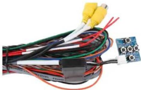
PARTS INCLUDED:

RVCGM-80M Module RVCGM-80M T-Harness LVDS Cable
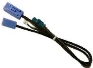
natural_image
Coiled black cable with blue and green connectors (no text or symbols visible)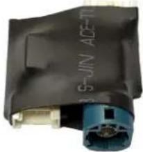
natural_image
Close-up of a black plastic device with blue connectors and a metallic connector (no visible text or symbols)
natural_image
Close-up of a green printed circuit board with multiple black push-button switches and connectors (no visible text or symbols)GVIF Video Cables LVDS Video Extension Board OSD Control Pad
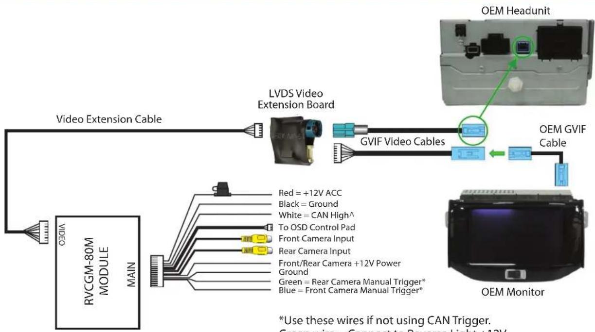
WIRING DIAGRAM:
flowchart
graph TD
    A["RVCGM-80M MODULE MAIN"] --> B["Video Extension Cable"]
    B --> C["LVDS Video Extension Board"]
    C --> D["GVIF Video Cables"]
    D --> E["OEM Headunit"]
    E --> F["OEM Monitor"]
    F --> G["Green = Rear Camera Manual Trigger*"]
    F --> H["Blue = Front Camera Manual Trigger*"]
    I["Red = +12V ACC"] --> C
    J["Black = Ground"] --> C
    K["White = CAN High^"] --> D
    L["To OSD Control Pad"] --> C
    M["Front Camera Input"] --> C
    N["Rear Camera Input"] --> C
    O["Front/Rear Camera +12V Power Ground"] --> C
    P["Green = Rear Camera Manual Trigger*"] --> C
    Q["Blue = Front Camera Manual Trigger*"] --> C
    style A fill:#f9f,stroke:#333
    style B fill:#ccf,stroke:#333
    style C fill:#cfc,stroke:#333
    style D fill:#fcc,stroke:#333
    style E fill:#cff,stroke:#333
    style F fill:#ffc,stroke:#333
    style G fill:#fff,stroke:#333
    style H fill:#fff,stroke:#333
    style I fill:#fff,stroke:#333
    style J fill:#fff,stroke:#333
    style K fill:#fff,stroke:#333
    style L fill:#fff,stroke:#333
    style M fill:#fff,stroke:#333
    style N fill:#fff,stroke:#333
    style O fill:#fff,stroke:#333
    style P fill:#fff,stroke:#333
    style Q fill:#fff,stroke:#333
*Use these wires if not using CAN Trigger.
Green wire = Connect to Reverse Light +12V
Blue wire = Connect to +12V using a toggle switch
^See Note below regarding wire color
CAN WIRE CONNECTION:
The RVCGM-80M detects the CAN communications in the vehicle. Tap the WHITE wire^ (Pin# 2) on the RVCGM-80M power harness to the GREEN wire (PIN# 28) on the 44 pin OEM connector behind the headunit. Reverse gear engagement is automatically detected and will power on the rear camera. The front camera will power on when the gear is put to Drive. The delay OFF of the front camera can be set in the OSD menu. Time delay OFF can be set from 1 to 60 seconds.
If for some reason the CAN connection cannot detect the reverse gear communication, connect the GREEN wire on the RVCGM-80M power harness (Rear Camera Manual Trigger) to the reverse light wire +12V. Do not connect the WHITE wire to the GM CAN line.
The Front camera also be also been manually triggered by connecting the BLUE wire (Front Camera Manual Trigger) to +12V.
^NOTE: Older generation RVCGM-80M may have a different colored wire on PIN #2. See diagram on the right for the wire location on the 30 pin power harness connector. (Wire view)

natural_image
Internal wiring diagram of an automotive connector with numbered pins (14, 15, 28) and colored wires (no text labels beyond pin numbers)GREEN wire Single CAN wire PIN# 28

text_image
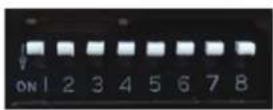
1 3 5 7 9 11 13 15 17 19 21 23 25 27 29 2 4 6 8 10 12 14 16 18 20 22 24 26 28 30DIP SWITCH SETTINGS:
Set all DIP switches to OFF (Up).
ON SCREEN DISPLAY (OSD) SETTINGS:
The OSD Setting Screen automatically pops up when the OSD Control Pad is connected.
natural_image
Coiled electronic circuit board with multicolored wires and connectors, no visible text or symbolsOSD Control Pad
Use the OSD menu to make the necessary settings. Remember to Run Save&Reboot after the settings are made. Unplug the OSD Control Pad after setting the cameras and keep it in a secure location in case it is needed to change the settings.
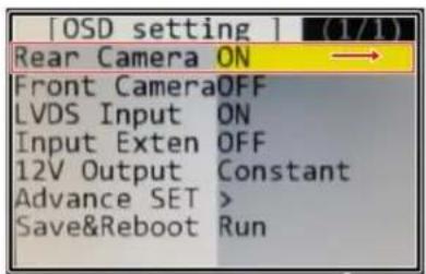
REAR CAMERA SETTING
text_image
[OSD setting ] (1/1) Rear Camera ON Front CameraOFF LVDS Input ON Input Exten OFF 12V Output Constant Advance SET > Save&Reboot Run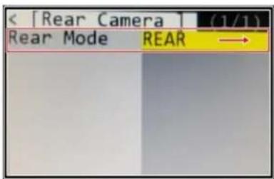
text_image
[Rear Camera] (1/1) Rear Mode REAR →
text_image
[Rear Mode] (1/1) Rear Input OEM →
text_image
Rear Input Aftermarket OEM When installing Aftermarket Rear View Camera When the car is equipped with OEM Rear View Camera
text_image
[OSD setting ] (1/1) Rear Camera ON Front CameraOFF LVDS Input ON Input Exten OFF 12V Output Constant Advance SET > Save&Reboot Run To Save Changes, must press this button at the end
text_image
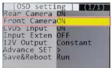
EnterFRONT CAMERA SETTING
text_image
[OSD setting] (1/1) Rear Camera ON Front Camera ON LVDS Input ON Input Exten OFF 12V Output Constant Advance SET > Save&Reboot Run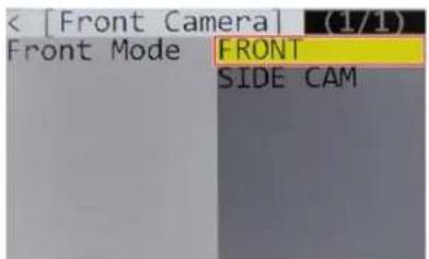
text_image
[Front Camera] (1/1) Front Mode FRONT SIDE CAM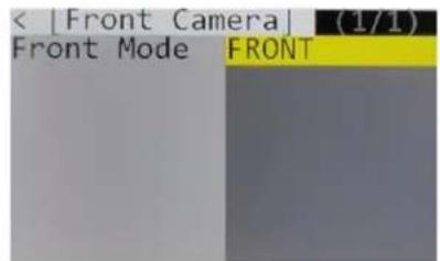
text_image
< [Front Camera] (1/1) Front Mode FRONT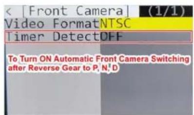
text_image
[Front Camera] (1/1) Video FormatNTSC Timer DetectOFF To Turn ON Automatic Front Camera Switching after Reverse Gear to P, N, D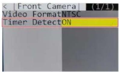
text_image
< |Front Camera| (1/1) Video FormatNTSC Timer DetectON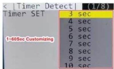
text_image
< |Timer Detect| (1/8) Timer SET 1-60Sec Customizing 3 sec 4 sec 5 sec 6 sec 7 sec 8 sec 9 sec 10 sec
text_image
[OSD setting ] (1/1) Rear Camera ON Front Camera OFF LVDS Input ON Input Exten OFF 12V Output Constant Advance SET > Save&Reboot Run To Save Changes, must press this button at the end.
text_image
ODI EnterThe front Camera will automatically show on the screen when the gear is put to Drive from Reverse. Delay OFF time can be set from 1 to 60 seconds after a putting the car to drive from reverse. See setting image above.
VEHICLE APPLICATIONS:
Compatible with 7" MyLink Systems
BUICK
2012 - 2015
2013 - 2015
LaCrosse
Verano
CHEVROLET
2013 - 2015
2013 - 2015
2012 - 2015
2013 - 2015
2013 - 2015
Camaro
Cruze
Equinox
Malibu
Volt
natural_image
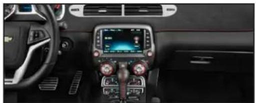
Interior view of a car dashboard and infotainment system (no visible text or symbols)2015 Camaro Radio

natural_image
Interior view of a car dashboard with digital navigation screens and steering wheel (no visible text or symbols)2015 Malibu Radio

rev.1221224 of 4