
WISE-3620 - Router Advantech - Free user manual and instructions
Find the device manual for free WISE-3620 Advantech in PDF.


| Product type | Industrial IoT Router |
| Brand | Advantech |
| Model | WISE-3620 |
| Dimensions (W x D x H) | 100 x 80 x 25 mm (approx.) |
| Weight | 200 g (approx.) |
| Power supply | 12V DC, 2-pin terminal block |
| Power consumption | 5W (typical) |
| Network interfaces | 1x 10/100 Ethernet, 1x RS-232/485 |
| Cellular connectivity | 4G LTE (Cat M1/NB-IoT) with dual SIM |
| Wi-Fi | 802.11 b/g/n (2.4 GHz) |
| GPS | Built-in GNSS (GPS/GLONASS) |
| Mounting | DIN rail mountable |
| Operating temperature | -20°C to 70°C |
| Ingress protection | IP30 |
| Antenna connectors | 2x SMA (LTE), 1x RP-SMA (Wi-Fi) |
| LED indicators | Power, status, signal strength |
| Management | Web interface, SNMP, MQTT |
| Security features | VPN (IPSec/OpenVPN), firewall |
| Maintenance and cleaning | Wipe with dry cloth, avoid liquids |
| Spare parts and repairability | Replaceable antennas, terminal blocks, SIM tray |
Frequently Asked Questions - WISE-3620 Advantech
User questions about WISE-3620 Advantech
0 question about this device. Answer the ones you know or ask your own.
Ask a new question about this device
Download the instructions for your Router in PDF format for free! Find your manual WISE-3620 - Advantech and take your electronic device back in hand. On this page are published all the documents necessary for the use of your device. WISE-3620 by Advantech.
USER MANUAL WISE-3620 Advantech
natural_image
Illustration of four electronic circuit boards with white outlines on a purple background (no text or symbols)WISE-3610
Wireless IoT LoRa Network Gateway
Copyright
The documentation and the software included with this product are copyrighted 2019 by Advantech Co., Ltd. All rights are reserved. Advantech Co., Ltd. reserves the right to make improvements in the products described in this manual at any time without notice. No part of this manual may be reproduced, copied, translated or transmitted in any form or by any means without the prior written permission of Advantech Co., Ltd. Information provided in this manual is intended to be accurate and reliable. However, Advantech Co., Ltd. assumes no responsibility for its use, nor for any infringements of the rights of third parties, which may result from its use.
Acknowledgements
ARM is trademarks of ARM Corporation.
NXP is trademarks of NXP Corporation.
All other product names or trademarks are properties of their respective owners.
Product Warranty (2 years)
Advantech warrants to you, the original purchaser, that each of its products will be free from defects in materials and workmanship for two years from the date of purchase.
This warranty does not apply to any products which have been repaired or altered by persons other than repair personnel authorized by Advantech, or which have been subject to misuse, abuse, accident or improper installation. Advantech assumes no liability under the terms of this warranty as a consequence of such events.
Because of Advantech's high quality-control standards and rigorous testing, most of our customers never need to use our repair service. If an Advantech product is defective, it will be repaired or replaced at no charge during the warranty period. For out-of-warranty repairs, you will be billed according to the cost of replacement materials, service time and freight. Please consult your dealer for more details.
If you think you have a defective product, follow these steps:
-
Collect all the information about the problem encountered. (For example, CPU speed, Advantech products used, other hardware and software used, etc.) Note anything abnormal and list any onscreen messages you get when the problem occurs.
-
Call your dealer and describe the problem. Please have your manual, product, and any helpful information readily available.
-
If your product is diagnosed as defective, obtain an RMA (return merchandise authorization) number from your dealer. This allows us to process your return more quickly.
-
Carefully pack the defective product, a fully-completed Repair and Replacement Order Card and a photocopy proof of purchase date (such as your sales receipt) in a shippable container. A product returned without proof of the purchase date is not eligible for warranty service.
-
Write the RMA number visibly on the outside of the package and ship it prepaid to your dealer.
Part No. 2006028600 Edition 1
Printed in China February 2019
Declaration of Conformity
Federal Communication Commission Interference Statement
This device complies with Part 15 of the FCC Rules. Operation is subject to the following two conditions: (1) This device may not cause harmful interference, and (2) this device must accept any interference received, including interference that may cause undesired operation.
This equipment has been tested and found to comply with the limits for a Class B digital device, pursuant to Part 15 of the FCC Rules. These limits are designed to provide reasonable protection against harmful interference in a residential installation. This equipment generates, uses and can radiate radio frequency energy and, if not installed and used in accordance with the instructions, may cause harmful interference to radio communications. However, there is no guarantee that interference will not occur in a particular installation. If this equipment does cause harmful interference to radio or television reception, which can be determined by turning the equipment off and on, the user is encouraged to try to correct the interference by one of the following measures:
■ Reorient or relocate the receiving antenna.
■ Increase the separation between the equipment and receiver.
■ Connect the equipment into an outlet on a circuit different from that to which the receiver is connected.
Consult the dealer or an experienced radio/TV technician for help.
FCC Caution: Any changes or modifications not expressly approved by the party responsible for compliance could void the user's authority to operate this equipment.
This transmitter must not be co-located or operating in conjunction with any other antenna or transmitter.
For operation within 5.15 \~ 5.25GHz frequency range, it is restricted to indoor environment. This device meets all the other requirements specified in Part 15E, Section 15.407 of the FCC Rules.
Radiation Exposure Statement
This equipment complies with FCC radiation exposure limits set forth for an uncontrolled environment. This equipment should be installed and operated with minimum distance 35 between the radiator & your body.
Industry Canada Statement
This device complies with ISED's licence-exempt RSSs. Operation is subject to the following two conditions: (1) This device may not cause harmful interference, and (2) this device must accept any interference received, including interference that may cause undesired operation.
(i) the device for operation in the band 5150-5250 MHz is only for indoor use to reduce the potential for harmful interference to co-channel mobile satellite systems;
(ii) the maximum antenna gain permitted for devices in the band 5725-5850 MHz shall be such that the equipment still complies with the e.i.r.p. limits specified for point-to-point and non-point-to-point operation as appropriate; and
(iii) Users should also be advised that high-power radars are allocated as primary users (i.e. priority users) of the bands 5650-5850 MHz and that these radars could cause interference and/or damage to LE-LAN devices.
Avertissement:
Radiation Exposure Statement
This equipment complies with ISED radiation exposure limits set forth for an uncontrolled environment. This equipment should be installed and operated with minimum distance 44 between the radiator & your body.
This device complies with Directive 2014/53/EU issued by the Commission of the European Community.
Declaration of Conformity
Hereby, [Advantech Co., Ltd.] declares that the radio equipment type [designation of type of radio equipment] is in compliance with Directive 2014/53/EU.
The full text of the EU declaration of conformity is available at the following internet address:
The frequency and maximum transmitted power in EU are listed as below,
2412 - 2472 MHz: XX.XX dBM
5180 - 5240 MHz: XX.XX dBM
5260 - 5230 MHz: XX.XX dBM
5500 - 5700 MHz: XX.XX dBM
- WLAN 5GHz:
Operations in the 5.15-5.35GHz band are restricted to indoor usage only.
VCCI Certification
This is a Class B product based on the standard of the Voluntary Control Council for Interference from Information Technology Equipment (VCCI). If this is used near a radio or television receiver in a domestic environment, it may cause interference. Install and use the equipment according to the instruction manual.
Class B ITE
Before installation, please ensure the following items have been shipped.
■ 1 x WISE-3610 (refer to ordering information for different region)
■ 1 x Power Adapter (P/N: 96PSA-A36W12R1)
■ 2 x Wi-Fi Dual Band Antenna (P/N: 1750008001-01)
■ LoRa Antenna (Different region will pack different LoRa antenna)
■ 2 x Wall Mount Becket (P/N: 1960082071N001)
4 x Wall Mount Becket Screw (P/N: 1930000071)
Ordering Information
Part No. Description
| WISE-3610ILS-51A1N | WISE-3610 Private LoRa Network IoT Gateway NA915 |
| WISE-3610ILS-51A1E | WISE-3610 Private LoRa Network IoT Gateway EU868 |
| WISE-3610ILS-51A1J | WISE-3610 Private LoRa Network IoT Gateway JP923 |
| WISE-3610ILS-51A1T | WISE-3610 Private LoRa Network IoT Gateway TW920 |
| WISE-3610ILS-51A1C | WISE-3610 Private LoRa Network IoT Gateway CN470 |
Optional Accessories
| Part No. Description |
| 1700001524 Power Cable 3-pin 180cm, USA type |
| 170203183C Power Cable 3-pin 180cm, Europe type |
| 170203180A Power Cable 3-pin 180cm, UK type |
| 1700008921 Power Cable 3-pin PSE Mark 183cm |
| 1750008424-01 3G/LTE Antenna Dipole 4dBi Full Band |
| 1750008669-01 3G/LTE RX Diversity Antenna Cable IPEX to IPEX Connector |
| 968EMW0093 Mini PCIE HSPA 3G Card with Rx Diversity |
| 1700001524 Power Cable 3-pin 180cm, USA type |
| 170203183C Power Cable 3-pin 180cm, Europe type |
| 170203180A Power Cable 3-pin 180cm, UK type |
Safety Instructions
- Read these safety instructions carefully.
- Keep this User Manual for later reference.
- Disconnect this equipment from any AC outlet before cleaning. Use a damp cloth. Do not use liquid or spray detergents for cleaning.
- For plug-in equipment, the power outlet socket must be located near the equipment and must be easily accessible.
- Keep this equipment away from humidity.
- Put this equipment on a reliable surface during installation. Dropping it or letting it fall may cause damage.
- The openings on the enclosure are for air convection. Protect the equipment from overheating. DO NOT COVER THE OPENINGS.
- Make sure the voltage of the power source is correct before connecting the equipment to the power outlet.
- Position the power cord so that people cannot step on it. Do not place anything over the power cord.
- All cautions and warnings on the equipment should be noted.
- If the equipment is not used for a long time, disconnect it from the power source to avoid damage by transient overvoltage.
- Never pour any liquid into an opening. This may cause fire or electrical shock.
- Never open the equipment. For safety reasons, the equipment should be opened only by qualified service personnel.
- If one of the following situations arises, get the equipment checked by service personnel:
■ The power cord or plug is damaged.
■ Liquid has penetrated into the equipment.
■ The equipment has been exposed to moisture.
■ The equipment does not work well, or you cannot get it to work according to the user's manual.
■ The equipment has been dropped and damaged.
■ The equipment has obvious signs of breakage.
DISCLAIMER: This set of instructions is given according to IEC 704-1. Advantech disclaims all responsibility for the accuracy of any statements contained herein.
Contents
Chapter 1 General Introduction ......1
1.1 Introduction 2
1.1.1 Product Features 2
1.2 Mechanical Specifications.... 4
1.3 Electrical Specifications 4
1.4 Environmental Specifications 4
Chapter 2 H/W Installation....5
2.1 Introduction 6
2.1.1 WISE-3610 I/O Indication 6
Figure 2.1 WISE-3610 Front View 6
Figure 2.2 WISE-3610 Rear View.... 6
2.1.2 WISE-3610 Antenna Connectors.... 6
Figure 2.3 Antenna SMA in front panel....6
Figure 2.4 Antenna SMA in rear panel 7
Table 2.1: WWAN related materials ..... 7
2.1.3 LED Indication....7
Table 2.2: WISE-3610 LED Indication....7
Figure 2.5 WISE-3610 LED locations 8
2.1.4 Reset Button 8
Figure 2.6 Rest button location....8
2.1.5 Ethernet Connector (WAN, LAN) 8
2.1.6 USB 3.0 Port 9
2.1.7 COM Port 9
2.1.8 Power Input Connector 10
2.1.9 Micro SD Connector.... 10
2.1.10 Micro SIM Connector 11
2.2 On Board Connectors and Switches 12
2.2.1 Connector and switch lists 12
2.2.2 Connector Settings 12
Figure 2.7 SD Slot 12
Figure 2.8 Mini-PCIE CONNECTOR 15
Figure 2.9 Hardware Switch for serial type selection.... 15
Figure 2.10CN18 and 3G module connection guidance.... 16
2.3 WISE-3610 Hardware Installation 16
2.3.1 Mounting Assembly Method.... 16
2.3.2 Enable WWAN feature with hardware installation 17
Chapter 3 Software Functionality......21
3.1 WEB GUI Login 22
3.2 Gateway Deployment Function Comparison.... 23
3.3 Gateway Deployment (WAN) 23
3.3.1 NorthBound.... 23
3.3.2 Protocol.... 23
3.3.3 WAN / WAN Failover 25
3.3.4 SouthBound 25
3.4 Gateway Deployment (WWAN).... 26
3.4.1 NorthBound.... 26
3.4.2 SouthBound 27
3.4.3 Cellular 27
3.4.4 Enable.... 27
3.4.5 SIM 27
3.4.6 Cellular Status 28
3.5 Gateway Deployment (2.4GHz WIFI) 28
3.5.1 NorthBound....28
3.5.2 Scan 2.4GHz AP Button 29
3.5.3 Join Network Button.... 29
3.5.4 WPA passphrase 30
3.6 Gateway Deployment (5GHz WIFI) 31
3.7 System 31
3.7.1 Local Time 31
3.7.2 Hostname 31
3.7.3 Timezone 31
3.7.4 Enable NTP client 31
3.7.5 NTP server candidates 32
3.8 Administration 32
3.8.1 Old Password 32
3.8.2 Password and Confirmation.... 32
3.9 Backup / Flash Firmware 33
3.9.1 Generate archive 33
3.9.2 Perform reset 33
3.9.3 Upload archive.... 33
3.9.4 Keep settings 33
3.9.5 Flash image 33
3.9.6 Flash Firmware -Verify 34
3.10 Reboot 34
3.11 Diagnostics 35
3.12 Security 35
3.12.1 Remote Management 35
3.13 DMZ 36
3.13.1 DMZ 36
3.13.2 IPv4 address 36
3.14 Port Forwarding 36
3.14.1 Port Forwarding 36
3.15 MAC Filter 37
3.15.1 MAC Filter.... 37
3.16 PPTP/L2TP 38
3.16.1 Disabled.... 38
3.16.2 Protocol.... 38
3.16.3 Server IP 38
3.16.4 PAP/CHAP username and PAP/CHAP password 38
3.17 IPSec 39
3.17.1 NAT Traversal.... 39
3.17.2 Add button 39
3.17.3 IKEv1/IKEv2 39
3.17.4 Local Peer IP 39
3.17.5 Local Subnet.... 39
3.17.6 Local ID.... 39
3.17.7 Remote Peer IP 39
3.17.8 Remote Subnet.... 40
3.17.9 Remote ID....40
3.17.10Auth By 40
3.17.11 PSK Key 40
3.17.12CA....40
3.17.13Local Certificate 40
3.17.14Local Key 40
3.17.15 Remote Certificate 41
3.17.16IKE Algorithms 41
3.17.17 IKE Lifetime 41
3.17.18 ESP Algorithm 41
3.17.19 Perfect Forward Secret.... 41
3.17.20SA Lifetime.... 41
3.17.21DPD Delay 41
3.17.22DPD Timeout 42
3.17.23DPD Action 42
3.17.24XAuth 42
3.17.25Username 42
3.17.26Password 42
3.17.27Operation 42
3.18 Dynamic DNS.... 43
3.18.1 Enable....43
3.18.2 Service 43
3.18.3 Hostname.... 43
3.18.4Username 43
3.18.5 Password 43
3.18.6 Source of IP address 43
3.18.7 Network....43
3.18.8 URL 43
3.18.9 Check for changed IP every and Check-time unit.... 43
3.18.10 Force update every and Force-time unit 44
3.19 Modbus Configuration 44
3.19.1 Modbus Gateway 44
3.19.2 Interface 44
3.19.3 Baud Rate 45
3.19.4 Data Bits/Parity/Stop Bits.... 45
3.19.5 TCP Port 45
3.19.6 MAX TCP Connections 45
3.19.7 Frame Break (ms) 45
3.19.8 Slave Timeout (ms) 45
3.20 WEB Server 46
3.20.1 HTTPS Certificate 46
3.20.2 HTTPS Private Key.... 46
3.20.3 Remove old certificate and key.... 46
3.21 Syslog 46
3.21.1 Enable....46
3.21.2 Host.... 46
3.21.3 Port Number.... 47
3.22 WIFI Status 47
3.22.1 Wireless Overview 47
3.22.2 Associated Stations 47
3.23 WIFI Configuration 48
3.23.1 Wireless network is enabled 48
3.23.2 Channel 48
3.23.3 Transmit Power 48
3.23.4 ESSID 48
3.23.5 Mode 48
3.23.6 Hide ESSID.... 48
3.23.7 Mode 49
3.23.8 HT Mode 49
3.23.9 Inter SSID Isolation 49
3.23.10Force 40MHz mode 49
3.23.11ANI Enable.... 49
3.23.12 Dynamic Tx Chain Enable 49
3.23.13Encryption 50
3.23.14 Used Key Slot / Key#1 / Key#2 / Key#3 / Key#4 50
3.23.15 Cipher / Key 50
3.23.16 Cipher / Radius-Authentication-Server(/Port/Secret) / Radius-Account-Enable / NAS ID.... 50
3.23.17MAC-Address Filter 51
3.23.18MAC-List 51
3.24 Static Routes....52
3.25 Data and Charts.... 54
3.26 Management 55
3.27 LoRa Node Import....62
3.28 Payload Field 63
Chapter 4 WISE-PaaS...... 65
4.1 Configuration....66
4.1.1 Hostname 66
4.1.2 Port 66
Chapter 5 Advantech Services.... 67
5.1 Contact Information....68
5.2 Global Service Policy 68
5.2.1 Warranty Policy.... 68
5.2.2 Repair Process 69
Chapter 1
General Introduction
This chapter gives background information on the WISE-3610.
Sections include:
Introduction
Specification
1.1 Introduction
WISE-3610 is Qualcomm Atheros (QCA) ARM Cortex-A based hardware platform, which is operating at OpenWRT, described as a Linux distribution for embedded networking devices. The Advantech WISE-3610 Industrial Gateway is Advantech LPWAN IoT gateway design for smart city, Industrial 4.0 applications, even those in harsh environment, leveraging wireless sensor technology. This LPWAN IoT gateway can aggregate both the wireless sensor networks (WSN), including Low Power WAN (LPWAN) technology by Advantech Private LoRa technology – WISE-Link, wired sensors and ties them into an IP network. With modular slot design, it can agilely adapt to a variety of wireless technologies at regional RF bands, wireless communication protocol by various uplink requirement and quickly go to market.
The main features of WISE-3610 are:
Qualcomm Atheros Quad-Core ARM Cortex-A7 SoC
■ Built-in Dual Band Concurrent Wi-Fi MU-MIMO (2x2)
■ LPWAN Private LoRa (WISE-Link) Connectivity
■ WAN x1 / LAN x1 Gigabit Ethernet
■ Integration of Modbus TCP and Modbus RTU network Translator
■ IPSec / L2TP VPN Traffic Encryption
■ Rich Network Scenario by S/W Configuration
■ WAN / WWAM Failover backup support
■ WWAN Dual SIM Failover backup support
■ Modularization hardware design
■ OpenWRT BSP embedded
■ Web UI user interface
■ Support wide temperature -20 \~ 70 °C
1.1.1 Product Features
| Processor System CPU QCA Quad-core ARM Cortex A7 CPU 716 MHz | ||
| Memory | Technology DDR3L 1066MHz | |
| Capacity On-board 256MB | ||
| Flash 128MB | ||
| Ethernet | WAN 1 x 10/100/1000Mbps | |
| LAN 1 x 10/100/1000 Mbps | ||
| COM (Serial) | H/W Selection | RS-232/RS-422/RS-485 (default configures as RS-485) |
| ModBus | ModBus TCP / RTU Translator | |
| Security | VPN Engine | IPSec, L2TP |
| Connectivity | Wi-Fi | 2x2 Concurrent Dual Band 2.4Ghz/5Ghz |
| LoRa | 2x2 Private LoRa Network – WISE-Link | |
| Antenna | Wi-Fi | 2 2.4Ghz / 5Ghz @ 5dBi |
| LoRa | 2 433Mhz / 868Mhz / 915Mhz @ 1dBi | |
| Expansion Slot | Mini-PCIe | 1 Full size mini PCie slot for 3G WWAN module |
| SD Card | 1 Micro SD Socket up-to 128GB | |
| SIM | 2 Micro SIM Slot for WWAN dual SIM Failover | |
| Wi-Fi | Standard IEEE802.11a/b/g/n/ac | |
| Multiplexing OFDM | ||
| Modulation BPSK, QPSK, 16QAM, 64QAM, 256QAM (11ac) | ||
| Media Access CSMA/CA with ACK | ||
| Associated STA 100 stations per radio | ||
| Channel | 2.4Ghz:CH1-11: North America, TaiwanCH1-13: EU, Japan, China5Ghz:CH36, 40, 44, 48 (Band 1):North America, EU, Japan, ChinaCH149, 153, CH157, 161, 165 (Band4):North America, Taiwan, China | |
| Bandwidth HT20/HT40/HT80 | ||
| Max TX Power | The maximum allowable RF power level is subject to specified nation regulation2.4Ghz < 20dBm5Ghz < 23dBm | |
| RX Sensitivity | 2.4Ghz:HT20 (11n): -64 dBm at MCS 7/15HT40 (11n): -61dBm at MCS 7/155Ghz:HT20 (11n): -64dBm at MCS7/15HT40 (11n): -61dBm at MCS 7/15HT20 (11ac): -57dBm at MCS9HT40 (11ac): -54dBm at MCS9HT80 (11ac): -51dBm at MCS9 | |
| LoRa | Standard Sub-Ghz radio station regulation | |
| Bandwidth 125Khz / 250Khz / 500Khz | ||
| Multiplexing TDMA | ||
| Modulation LoRa | ||
| Freq. Band CN 470Mhz, EU 868Mhz, NA 915Mhz, AS 923Mhz | ||
| Media Access | WISE-Link semi-persistent scheduling (SPS) with ACK | |
| Associated Node 500 nodes | ||
| Data Rate | Spread Factor (SF) 7 - 12 | |
| Max TX Power | The maximum allowable RF power level is subject to specified nation regulationLoRa < 18dBm | |
| RX Sensitivity | LoRa > -136dBm at SF = 12 / 125KHzLoRa > -133dBm at SF = 12 / 250KHzLoRa > -130dBm at SF = 12 / 500KHz | |
| O.S | Linux | V 3.14 |
| Dimensions | W x L x T | 187.9mm x 150mm x 39mm |
| Weight | Net Weight (g) 990 gram | |
| Power | DC-In | 12V DC-In |
| Power Consumption | Watt | 18 watt (Max) |
| Environment | Operational Temperature | -20 ~ 70°C |
| Operating Humidity | 0% ~ 90% relative humidity, non-condensing | |
| Certifications Level CE / FCC / Class B / TELEC / SRRC / NCC | ||
1.2 Mechanical Specifications
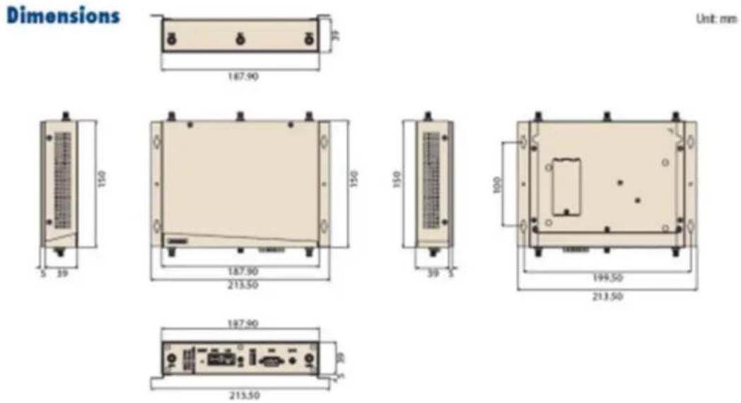
■ Dimension: 187.9mm x 150mm
Height: 39mm
■ Reference Weight: 990g (including wall mounting kits)
1.3 Electrical Specifications
■ Power supply type: DC-in 12V
■ RTC Super Capacitor: Panasonic (P/N: EECS0HD224)
– Typical voltage: 4.3V
– Nominal capacity: 0.22F
1.4 Environmental Specifications
■ Operating temperature: -20\~70°C (-4\~157°F)
Operating humidity: 0% \~ 90% relative humidity, non-condensing
■ Storage temperature: -40\~85°C (-40\~185°F)
■ Storage humidity: 60°C @ 95% RH Non-condensing
Vibration Loading During Operation: 1 Gms, IEC 60068-2-64, random, 5 \~ 500 Hz, 1 Oct/min, 1 hr/axis.
Chapter 2
H/W Installation
This chapter gives mechanical and connector information on the WISE-3610
Sections include:
Information of WISE-3610 I/O Indication
■ On Board Connectors and Switches
WISE-3610 Hardware Installation
2.1 Introduction
The following sections show the internal / external connectors and pin assignments for applications.
2.1.1 WISE-3610 I/O Indication
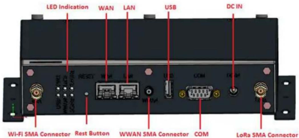
Figure 2.1 WISE-3610 Front View
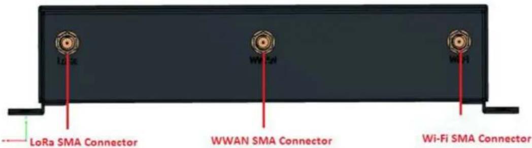
Figure 2.2 WISE-3610 Rear View
2.1.2 WISE-3610 Antenna Connectors
The WISE-3610 provides 6 SMA antenna connectors; all are assembled by default on housing. Wi-Fi, LoRa antennas (total are four) are packed in the package. To enable WWAN feature, need to have following table materials and assemble manually by the guides (refer to hardware installation guide 2.3.2):
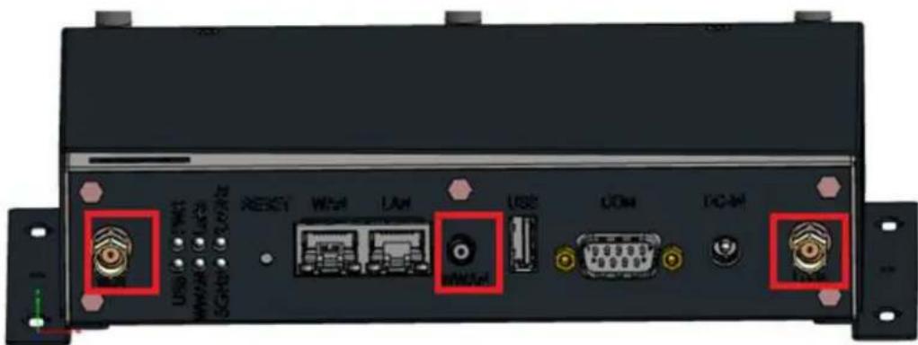
Figure 2.3 Antenna SMA in front panel
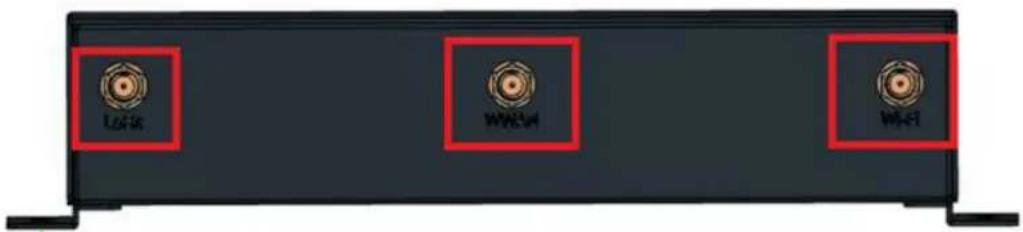
Figure 2.4 Antenna SMA in rear panel
Table 2.1: WWAN related materials
| 968EMW0093 Mini PCIE HSPA 3G Card with Rx Diversity |
| 1750008424-01 3G/LTE Antenna Dipole 4dBi |
| 1750008669-01 3G/LTE RX Diversity Antenna Cable IPEX to IPEX Connector |
| 193B0204C0 Mini-PCI Express Card Screw |
2.1.3 LED Indication
Table 2.2: WISE-3610 LED Indication
| Name | Description |
| PWR Steady ON = Power UpOFF = Power Down | |
| USB Steady ON = USB device detectedBlinking = TX / RX TransmissionOFF = No USB device connected | |
| LoRa Steady ON = LoRa Module detectedBlinking = TX / RX TransmissionOFF = LoRa Module disabled | |
| WWAN Steady ON = WWAN Module detectedBlinking = TX / RX TransmissionOFF = No WWAN Module detected | |
| 2.4Ghz Blinking = TX / RX TransmissionOFF = 2.4G Wi-Fi interface disabled | |
| 5Ghz Blinking = TX / RX TransmissionOFF = 5G Wi-Fi interface disabled | |
| WAN Brown LED Blinking = 10M/100Mbps TX / RX TransmissionGreen LED Blinking = 1000Mbps TX / RX Transmission | |
| LAN Brown LED Blinking = 10M/100Mbps TX / RX TransmissionGreen LED Blinking = 1000Mbps TX / RX Transmission | |
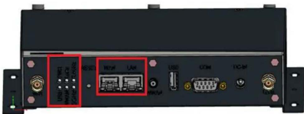
Figure 2.5 WISE-3610 LED locations
2.1.4 Reset Button
The WISE-3610 has a reset button on the front side. Press this button to activate the hardware reset function for more than 8 seconds.
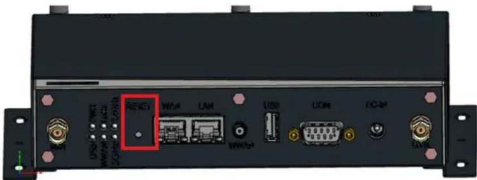
Figure 2.6 Rest button location
2.1.5 Ethernet Connector (WAN, LAN)
The WISE-3610 provides one RJ45 WAN and one RJ45 LAN interface connectors, they are fully compliant with IEEE802.3ab / IEEE 802.3u and IEEE 802.3x Flow Control 10/100/1000 Base-T CSMA/CD standards. These Ethernet ports provide standard RJ-45 connector with LED indicators to show Active/Link status.
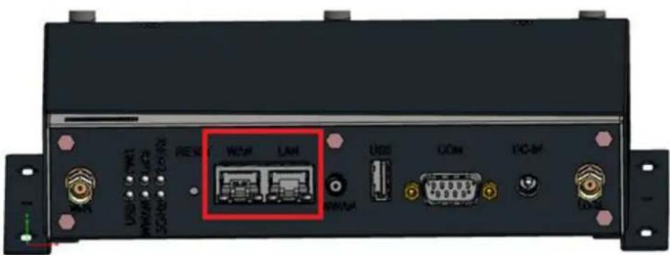
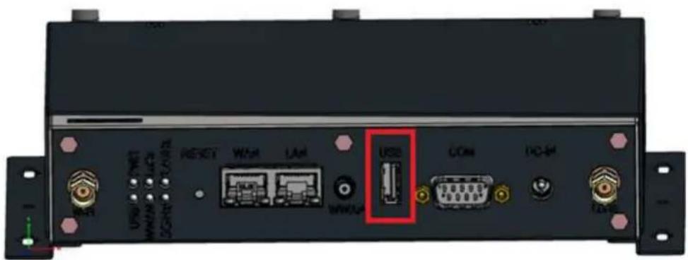
2.1.6 USB 3.0 Port
The WISE-3310 provides one USB 3.0 interface.
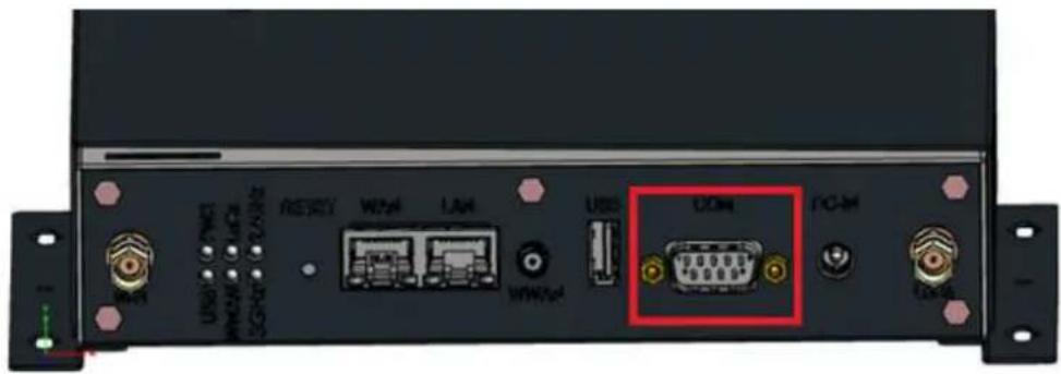
2.1.7 COM Port
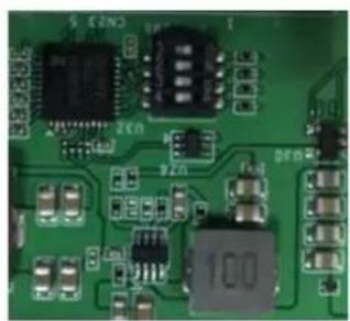
The WISE-3610 provides one serial D-sub 9 COM port which could be configured either one RS-232 / RS-422 / RS-485 interface for Modbus RTU feature. Open the housing to change hardware switch (Location at SW6) on PCBA for corresponding demand interface (default setup is RS-485).
RS-232 (1000) RS-422 (1100) Default: RS-485 (0100)
natural_image
Close-up of a green printed circuit board with integrated circuits and capacitors (no readable text or symbols)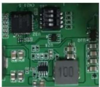
natural_image
Close-up of a green printed circuit board with various electronic components (no readable text or symbols)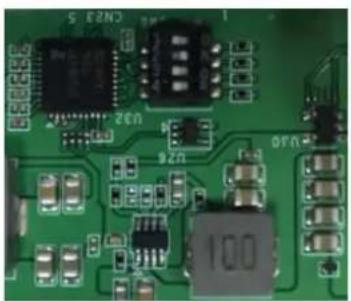
natural_image
Close-up of a green printed circuit board with various electronic components (no readable text or symbols)2.1.8 Power Input Connector
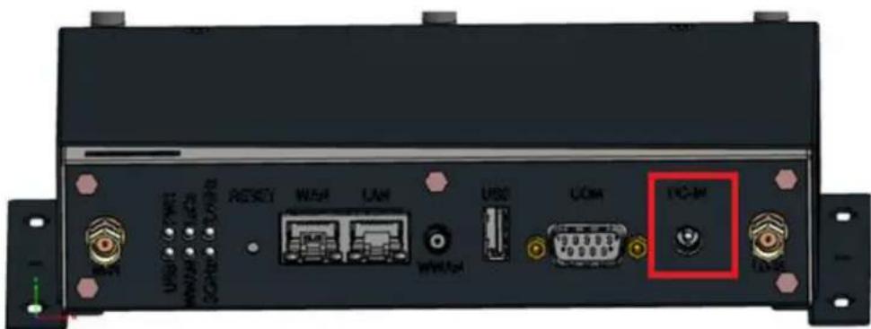
The WISE-3610 comes with a DC-jack header for 12V DC external power input. The Maximum power consumption is around 18 Watt.
2.1.9 Micro SD Connector
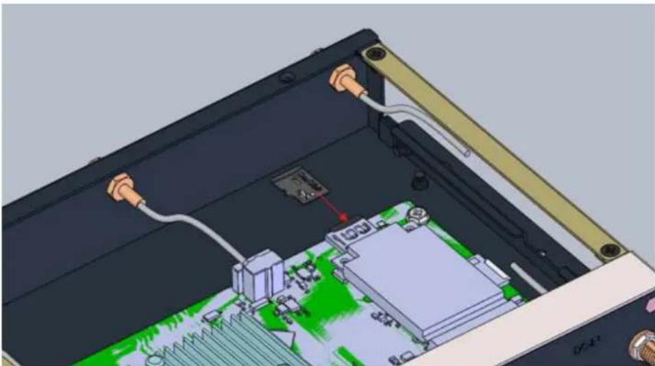
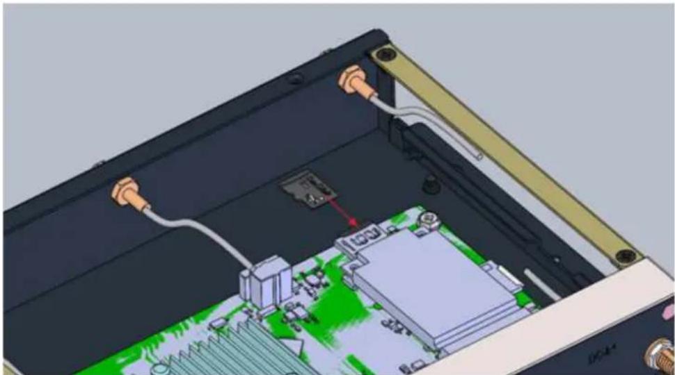
The WISE-3610 provides a Micro SD slot. Users can insert a Micro SD card easily by open the housing regarding to security concern (probably, users may save sensitive LoRa node collected data or other application into this Micro SD card supports up-to 128GB).
natural_image
3D CAD model of an electronic device showing internal components including a circuit board, connectors, and wiring (no text or symbols visible)2.1.10 Micro SIM Connector
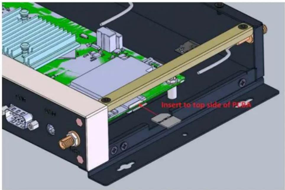
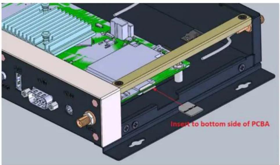
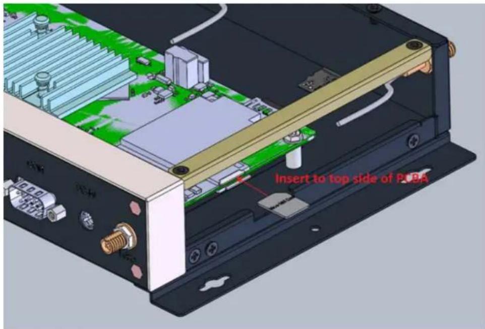
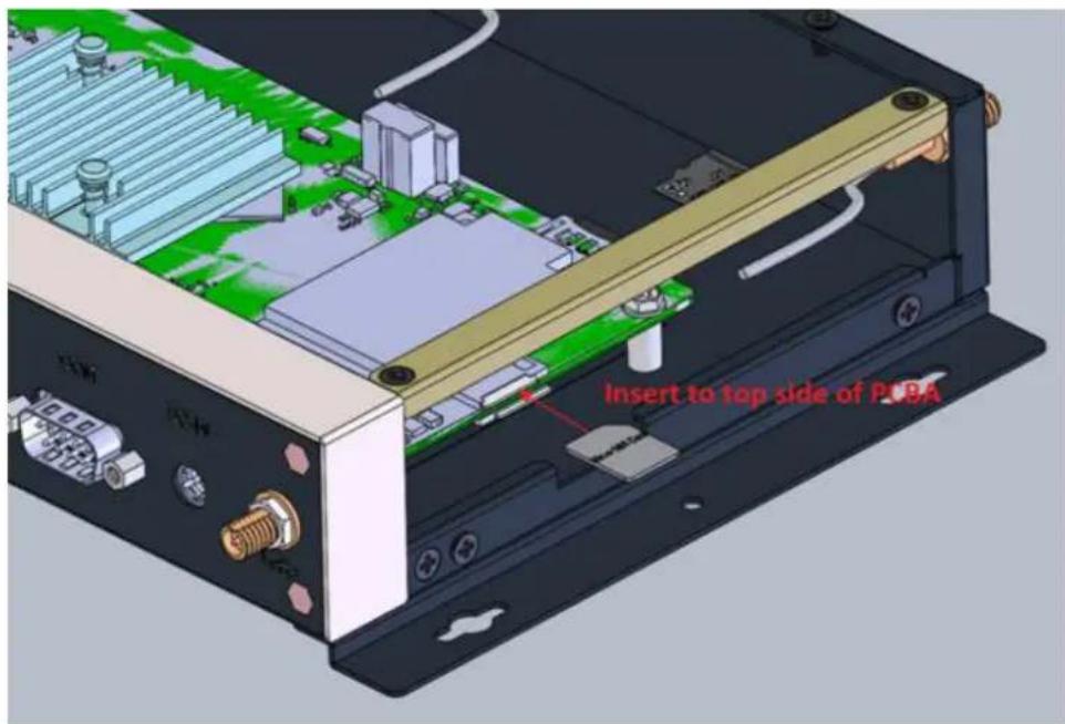
The WISE-3610 has two micro SIM slots. Users can insert two micro SIM cards manually. Two telecomm operating SIMs for backup each other if the connection loss. The SIM slot locations are on top and bottom of PCBA. The 1st priority SIM slot (Primary) is on top size of PCBA and the 2nd priority is on bottom side of PCBA. Refer to the following figures for indication.
2.2 On Board Connectors and Switches
2.2.1 Connector and switch lists
| CN12 SD Card Slot |
| CN28 Micro SIM Card Slot 1 (Primary) |
| CN27 Micro SIM Card Slot 2 (Secondary) |
| CN22 Mini-PCIe Card Slot |
| SW6 RS-232 / RS-422 / RS-485 hardware switch |
| CN18 WWAN IPEX Connector |
2.2.2 Connector Settings
2.2.2.1 CN12 Micro SD Card Slot
WISE-3610 support a Micro SD card slot up-to 128GB stored space
natural_image
3D diagram of an electronic device showing internal components with wires and a central circuit board (no text or symbols visible)Figure 2.7 SD Slot
2.2.2.2 Micro SIM Card Primary Slot (CN28)
2.2.2.3 Micro SIM Card Secondary Slot (CN27)
2.2.2.4 Mini PCIE (CN5)
WISE-3610 supports mini-pcie interface. Default support WWAN 3G module that are listed in "Table 2.1". The detailed pin definition is listed as below.
| mini-PCIe CN22 mini-PCIe | |||||
| 1 W | AKE# NC +V_LTE +3p | 3Vaux_1 2 | |||
| 3 COEX1# NC GND GND_ | 1 4 | ||||
| 5 COEX2# NC NC +1p5V_ | 1 6 | ||||
| 7 CLKREQ# | NC LTE_UIM_PWR | WR UIM_PWR | 8 | ||
| 9 | GND_2 | GND | LTE_UIM_DATA | UIM_DATA | 10 |
| 11 | REFCLK- | NC | LTE_UIM_CLK | UIM_CLK | 12 |
| 13 | REFCLK+ | NC | LTE_UIM_RESET | UIM_RESET | 14 |
| 15 | GND_3 | GND | NC | UIM_VPP | 16 |
| 17 | Reserved_6/UIM_C8 | NC GND GND_4 18 | |||
| 19 | Reserved_5/UIM_C4 | NC | LTE_W_DIS# | W_DISABLE# | 20 |
| 21 | GND_5 | GND | LTE_RTS# | PERST# | 22 |
| 23 | PERn0 | NC | +V_LTE | +3p3Vaux_2 | 24 |
| 25 | PERp0 | NC GND | GND_6 26 | ||
| 27 | GND_7 | GND | NC +1p5V_2 28 | ||
| 29 | GND_8 | GND | NC | SMB_CLK | 30 |
| 31 | PETn0 | NC | NC | SMB_DATA | 32 |
| 33 | PETp0 | NC GND | GND_9 34 | ||
| 35 | GND_10 | GND | LTE_USB_D- | USB_D- | 36 |
| 37 | GND_11 | GND | LTE_USB_D+ | USB_D+ | 38 |
| 39 | +3p3Vaux_3 | +V_LTE | GND | GND_12 | 40 |
| 41 | +3p3Vaux_4 | +V_LTE | LTE_LED | LED_WWAN# | 42 |
| 43 | GND_13 | GND | LED_WLAN# | 44 | |
| 45 | Reserved_1 | NC | LED_WPAN# | 46 | |
| 47 | Reserved_2 | NC NC +1p5V_3 | 3 | 48 | |
| 49 | Reserved_3 | NC | GND | GND_14 | 50 |
| 51 | Reserved_4 | NC | +V_LTE | +3p3Vaux_5 | 52 |

Figure 2.8 Mini-PCIE CONNECTOR
2.2.2.5 Hardware switch (SW6)
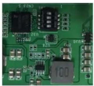
WISE-3610 supports a hardware switch to change RS-232 / RS-422 / RS-485 for selection. Default is RS-485 by manufacturer setting.
RS-232 (1000) RS-422 (1100) Default: RS-485 (0100)
natural_image
Close-up of a green printed circuit board with various electronic components (no readable text or symbols)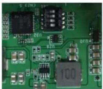
natural_image
Close-up of a green printed circuit board with integrated circuits and components (no readable text or symbols)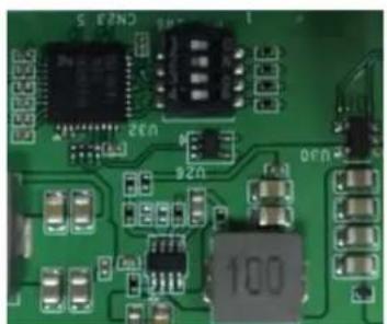
natural_image
Close-up of a green printed circuit board with various electronic components and traces (no readable text or symbols)Figure 2.9 Hardware Switch for serial type selection
2.2.2.6 WWAN IPEX Connector (CN18)
If there is WWAN 2nd antenna demand to have 3G Rx diversity feature by connecting CN18 IPEX to mini-PCie IPEX connector on the 3G module.
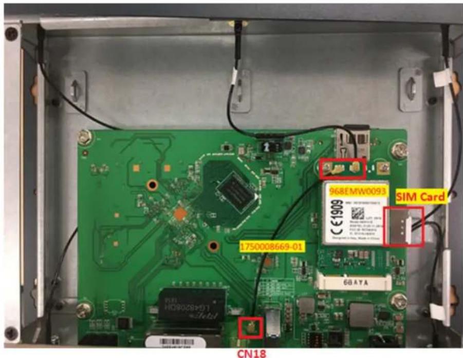
Figure 2.10 CN18 and 3G module connection guidance
2.3 WISE-3610 Hardware Installation
2.3.1 Mounting Assembly Method
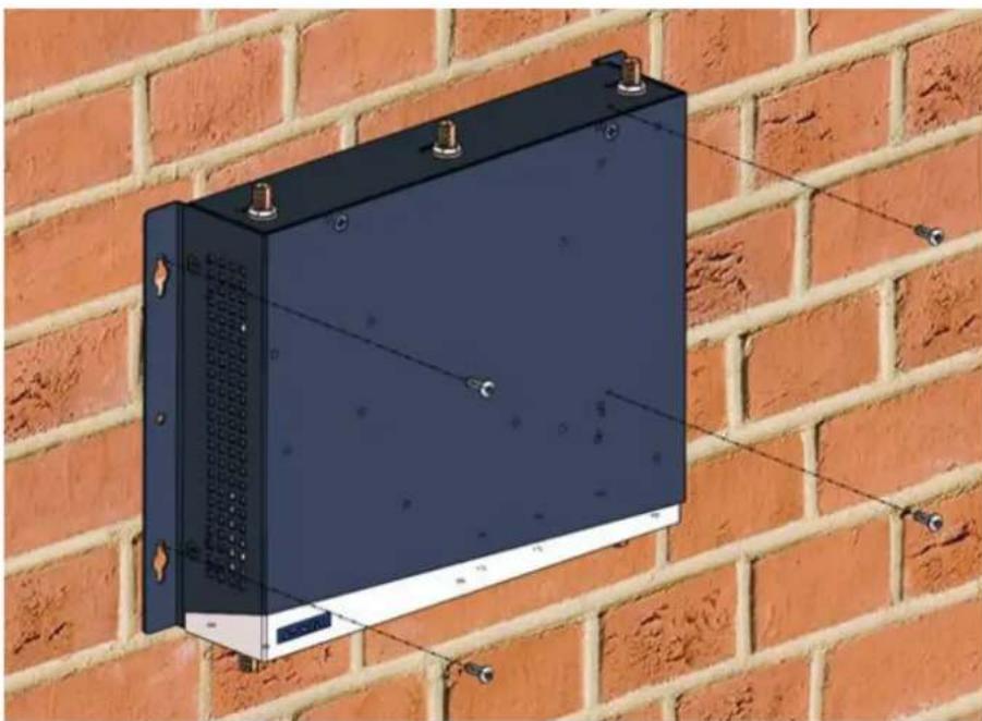
You can fix WISE-3310 to a wall by using wall mounting kit, as following figure.
natural_image
3D rendering of a black rectangular electronic device mounted on a brick wall, with mounting screws and wiring (no text or symbols visible)2.3.2 Enable WWAN feature with hardware installation
WISE-3610 has native support 3G and 4G LTE backhaul for WWAN card installation and accessories by the following order list and procedures:
| NO Content Description Qty Remark | |
| 1 968EMW0093 Mini PCIE HSPA 3G Card with Rx Diversity | 1 Frequency Band: 800/850, 900, AWS1700, 1900, 2100 |
| 2 EWM-C117FL02E LTE Card for Cat. 4(150Mbps / 50Mbps) | 1 LTE Bands:1, 3, 5, 7, 8, 20 (EU, Asia) |
| 3 EWM-C117FL07E LTE Card for Cat. 4(150Mbps / 50Mbps) | 1 LTE Bands:1, 3, 5, 8, 19 (JP NTT DoCoMo) |
| 4 1750008424-01 3G/LTE Antenna Dipole4dBi Full Band | 2 |
| 5 1750008669-01 3G/LTE RX DiversityAntenna Cable IPEX toIPEX Connector | 1 |
| 6 193B0204C0 Mini-PCI Express CardScrew | 2 |
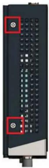
- Open WISE-3610 top case by releasing 6 screws around housing (from top and side view)
natural_image
Close-up of a black electronic device with multiple ports and buttons, no visible text or symbols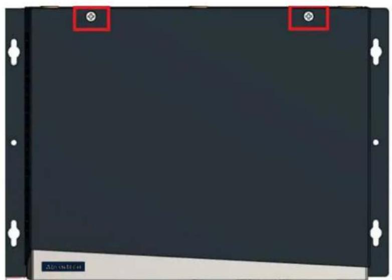
natural_image
Front view of a black electronic device with mounting flanges and a small beige base (no visible text or symbols)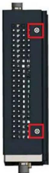
natural_image
Close-up of a black electronic device with grid-like components and two red square buttons (no visible text or symbols)- Install 968EMW0093 3G card into mini-PCIe slot on the top layer of WISE-3610 PCBA.
- Assembly 2 x antenna cables (one is 1750008669-01 and the other one has already provided in housing) on 3G module by the following figure guidance
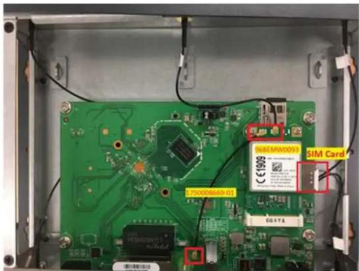
- Insert SIM Cards applied form local Internet Service Provider (ISP) into system (there is 2 SIM slots into WISE-3610 to support Dual-SIM Failover). One is on top of PCBA and the other is on the bottom side of PCBA at the same location shown on above photo.
- Close WISE-3610 top case.
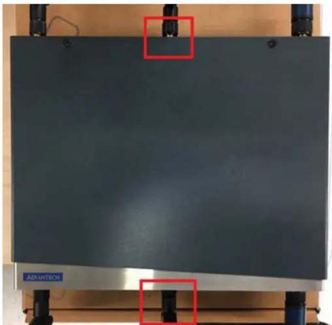
- Assembly 2x 1750008424-01 antennas in the front / rear of panels in the location of WWAN ports for H/W installation completion.
natural_image
Exterior view of a dark industrial machine with two red square highlights on top (no visible text or symbols)Chapter 3
Software Functionality
This chapter details the software configurations on the WISE-3610.
3.1 WEB GUI Login
-
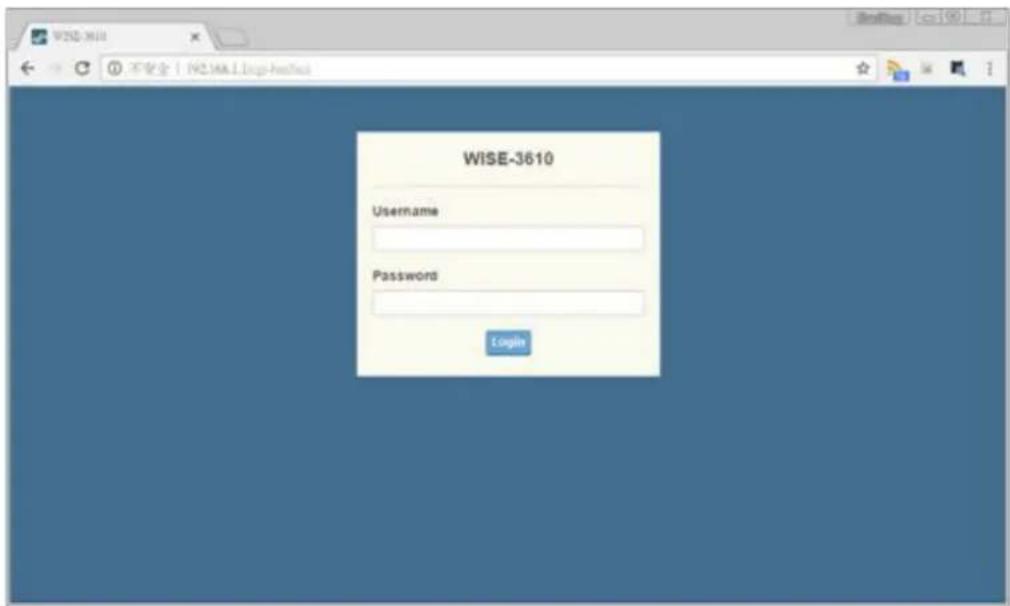
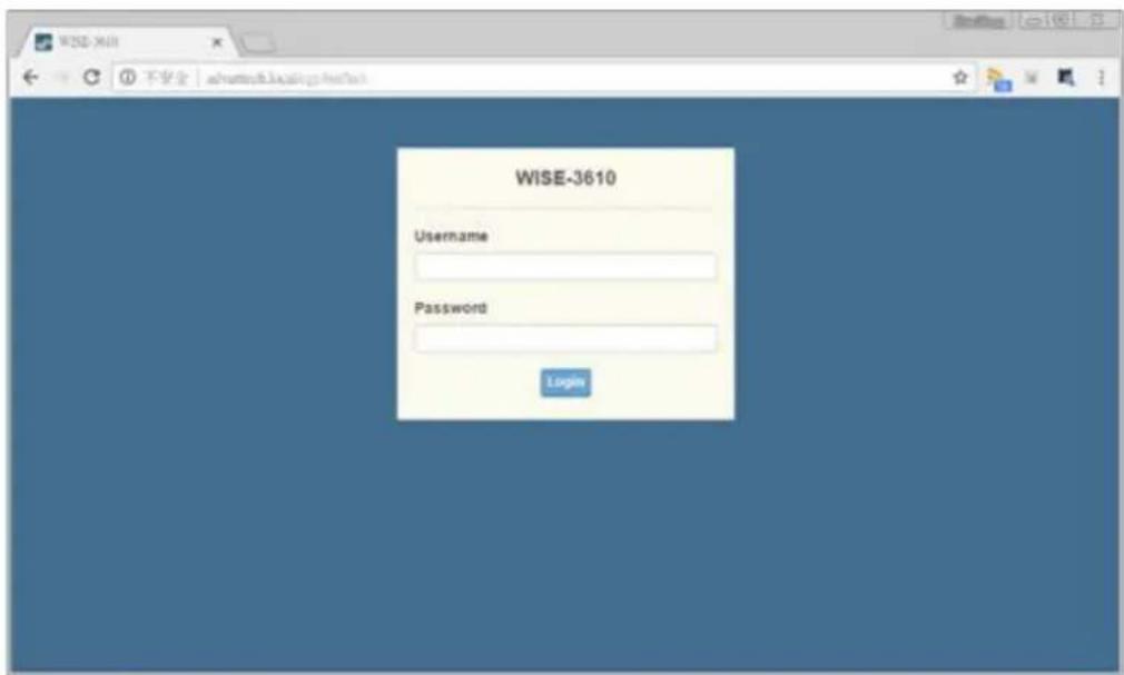
Access the WEB GUI, user can introduce http://192.168.1.1 on browser tool. User can also use http://advantech.local local domain technology to access Web GUI without figuring out the IP address of device.
-
The default WEB GUI Login account:
Username: root
Password: Advantech
3.2 Gateway Deployment Function Comparison
There are 4 kinds of Gateway Deployment modes applied to different deployment scenarios. The NorthBound configuration is "WAN", "WWAN", "2.4GHz WIFI", and "5GHz WIFI", respectively.
| Scenario NO | WWAN (3G/LTE) | WAN (Ethernet) | WISE-3610 DHCP Server @LAN/WLAN | WISE-3610 DHCP Client @WLAN | LAN (Ethernet) | Wi-Fi 2.4Ghz | Wi-Fi 5Ghz | LoRa | ||||
| 1 | O | O | O | X | O | AP | AP | AP | ||||
| 2 | O | X | O | X | O | AP | AP | AP | ||||
| 3 | X | X | X | O | O | STA + AP | AP | AP | ||||
| 4 | X | X | X | O | O | AP | STA + AP | AP | ||||
| Scenario NO | WISE-3610 Wi-Fi 2.4Ghz SSID | WISE-3610 Wi-Fi 5Ghz SSID | Remarks |
| 1 | Advantech | Advantech_5Ghz | Factory Default |
| 2 | Advantech | Advantech_5Ghz | |
| 3 | Connect uplink Root AP and broadcast SSID, which SSID is the same to uplink Root AP | Copy uplink SSID and add suffix "_5Ghz" over SSID Broadcast name. i.e.,XXXX_5Ghz | |
| 4 | Copy Uplink SSID and add suffix "_2Ghz" over SSID Broadcast name. i.e.,XXXX_2Ghz | Connect uplink Root AP and broadcast SSID, which SSID is the same to uplink Root AP |
3.3 Gateway Deployment (WAN)
3.3.1 NorthBound
Visit Network -> Gateway Deployment. The LoRa Gateway support 4 kinds of deployment scenarios to connect to customer's network, including "WAN", "WWAN", "2.4GHz WIFI" and "5GHz WIFI". The NorthBound item is used to choose the deployment scenarios.
3.3.2 Protocol
To choose the protocol for NorthBound connection. This protocol item only shows up when NorthBound is configured to WAN and it will be hided when NorthBound is configured to other values.
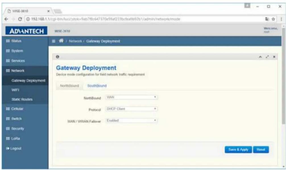
(1) DHCP Client
To choose DHCP client, and LoRa gateway will try to get IP on Ethernet WAN port via DHCP protocol.
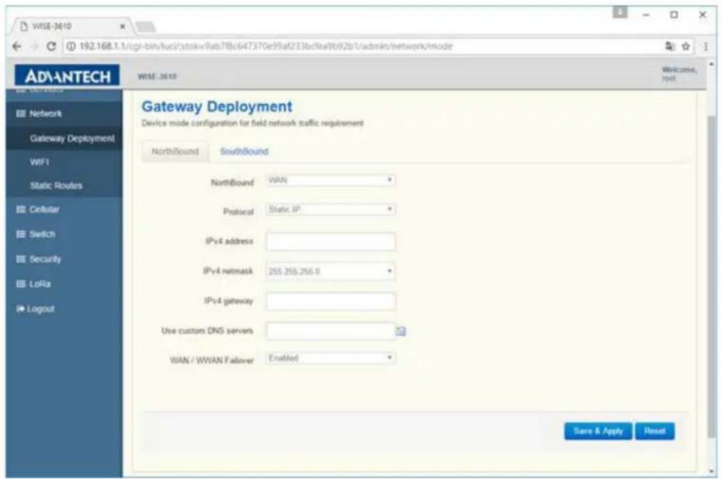
(2) Static IP
When user chooses Static IP, LoRa gateway will use static IP provided on Ethernet WAN port. In addition, user need to configure related IPv4 address, IPv4 netmask, IPv4 gateway, DNS servers.
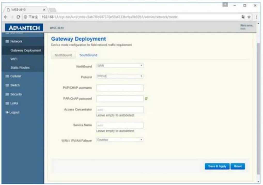
(3) PPPoE
When user chooses PPPoE, LoRa gateway will try to get IP on Ethernet WAN port via PPPoE protocol. In addition, user need to configure related PAP/CHAP username, and password. The Access Concentrator and Service Name are optional according to operator's environment.
3.3.3 WAN / WAN Failover
When WAN / WWAN Failover function is enabled, LoRa gateway will use Ethernet WAN or 3G module to connect to network. When LoRa gateway boots up, it prefers to use Ethernet WAN to connect to network, and will switch to 3G if there are no traffic in a minute. In addition, it will switch to Ethernet WAN if there are no traffic on 3G interface. When this function is disabled, only Ethernet WAN can be used to connect to network.
3.3.4 SouthBound
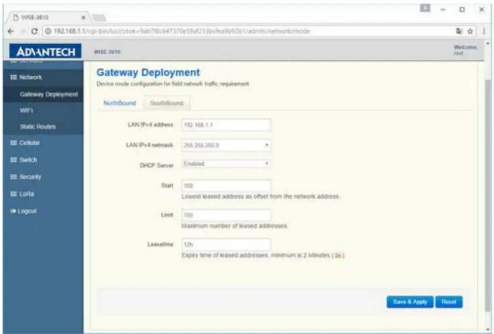
Visit Network -> Gateway Deployment. The SouthBound TAB includes LAN side IP and DHCP server related settings.
3.3.4.1 LAN IPv4 address and netmask
The SouthBound LAN side IP address and netmask setting
3.3.4.2 DHCP Server
The ON/OFF switch for LAN side DHCP Server function
3.3.4.3 Start
The start of IP address that DHCP Server will assign to client. User can input lowest leased address as offset from the LAN IPv4 address (e.g. 100) or input the exactly start of IP address (e.g. 192.168.1.100).
3.3.4.4 Limit
Maximum number of leased addresses from start of IP address. If user configures LAN side IP to 192.168.1.1/24, Start to 100 and Limit to 150, it means the IP address pool of DHCP server is 192.168.1.100\~192.168.1.249.
3.3.4.5 Leasetime
Lease time of assigned IP address from DHCP server
3.4 Gateway Deployment (WWAN)
3.4.1 NorthBound
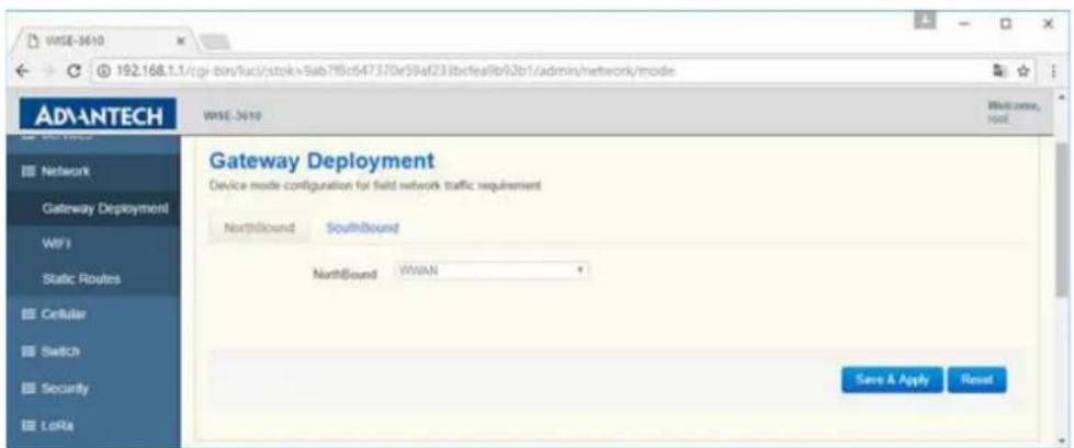
Visit Network -> Gateway Deployment. When NorthBound is configured to WWAN (Cellular), the 3G module is responsible for 3G network dial up using the information provided by USIM, user may not need to configure any items regarding to North-Bound.
3.4.2 SouthBound
The SouthBound setting are same as WAN mode.
3.4.3 Cellular
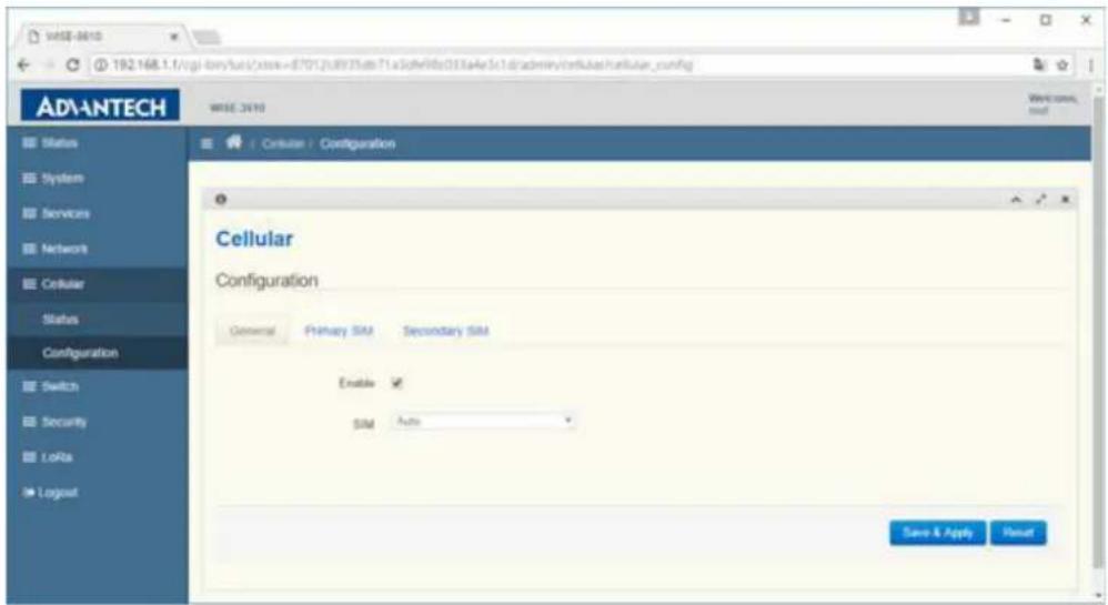
Visit Cellular -> Configuration. By default, LoRa gateway will use the information provided by USIM to dial up to Mobile network and user can keep the default setting.
3.4.4 Enable
The ON/OFF switch for 3G module dial up function.
3.4.5 SIM
There are 3 kinds of chooses for SIM item. The Auto means LoRa gateway will automatically switch between two USIM cards according to dial up status. That means when the 3G link with operator #1 is down, LoRa gateway will switch to operator #2. The Primary and Secondary mean LoRa gateway will only use first or secondary USIM to dial up, respectively.
3.4.6 Cellular Status
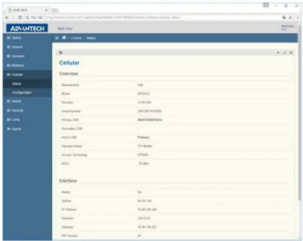
When LoRa gateway boots up, it will automatically connect to Mobile network using the information provided by USIM, and user can visit Cellular? Status to check link status.
3.5 Gateway Deployment (2.4GHz WIFI)
3.5.1 NorthBound
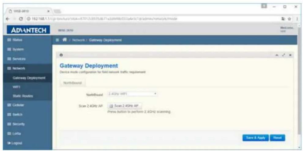
Visit Network -> Gateway Deployment. When NorthBound is configured to 2.4GHz WIFI, LoRa gateway will use 2.4GHz WIFI station to connect to uplink AP, and become a bridge AP. So, the clients on LAN port or 2.4GHz WIFI AP or 5GHz WIFI AP will get IP from uplink AP router via DHCP protocol.
3.5.2 Scan 2.4GHz AP Button
This button is used to scan 2.4GHz frequency and then LoRa gateway can connect to uplink AP router.
3.5.3 Join Network Button
After scanning, user can choose the specific uplink AP router and connect to it by pressing Join Network button.
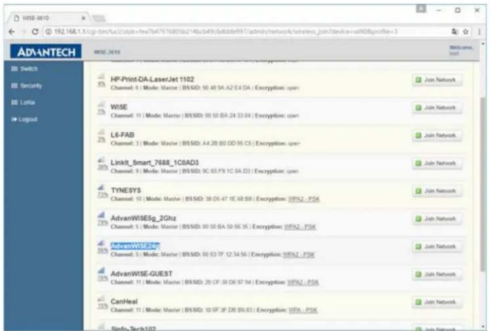
3.5.4 WPA passphrase
If uplink AP router has enabled security, user may need to input passphrase to connect to it correctly.
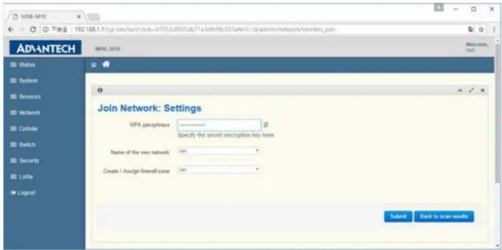
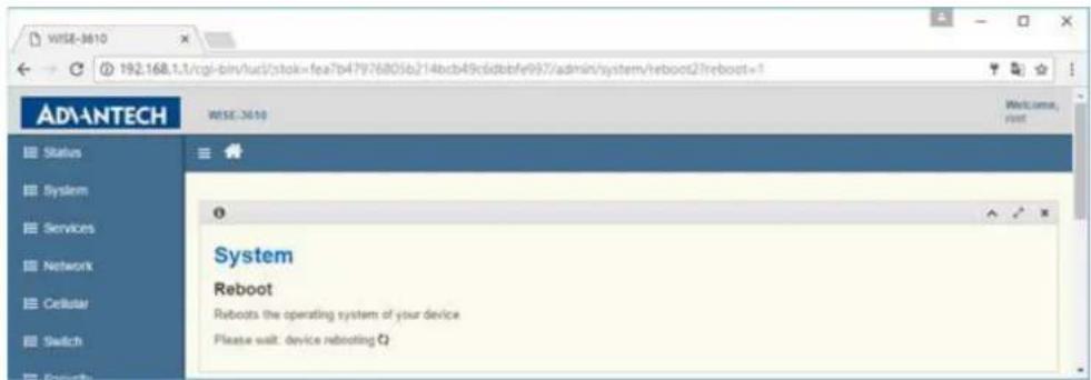
As pressing Submit button, LoRa gateway will reboot automatically to take configuration effect. When LoRa gateway boots up, it will get IP address from uplink AP router and LAN/WLAN side clients also need to get IP from uplink AP router in this mode.
3.6 Gateway Deployment (5GHz WIFI)
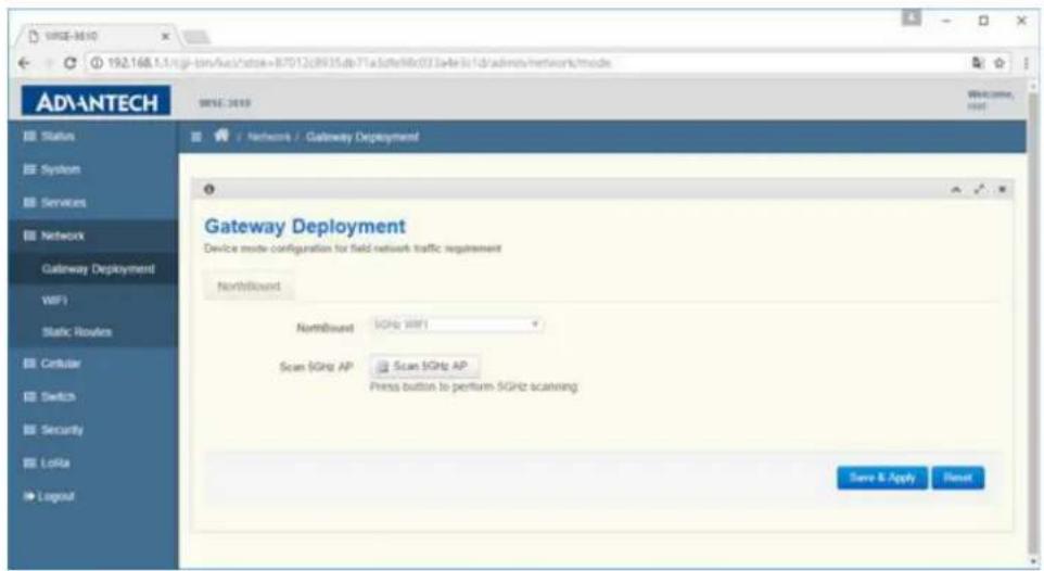
When NorthBound is configured to 5GHz WIFI, it uses 5G WIFI station to connect to uplink 5G AP, and it also enables 2.4G and 5G WIFI AP simultaneously. In this mode, 5G WIFI STA, 5G WIFI AP, 2.4G WIFI AP, and Ethernet LAN are bridged together, and device become an AP bridge. It uses DHCP client to get IP from uplink WIFI AP router. To connect to uplink AP, user should press "Scan 5GHz AP" button, and follow the wizard procedure. The configuration steps are like 2.4GHz WIFI steps, and user can refer 2.4GHz WIFI steps.
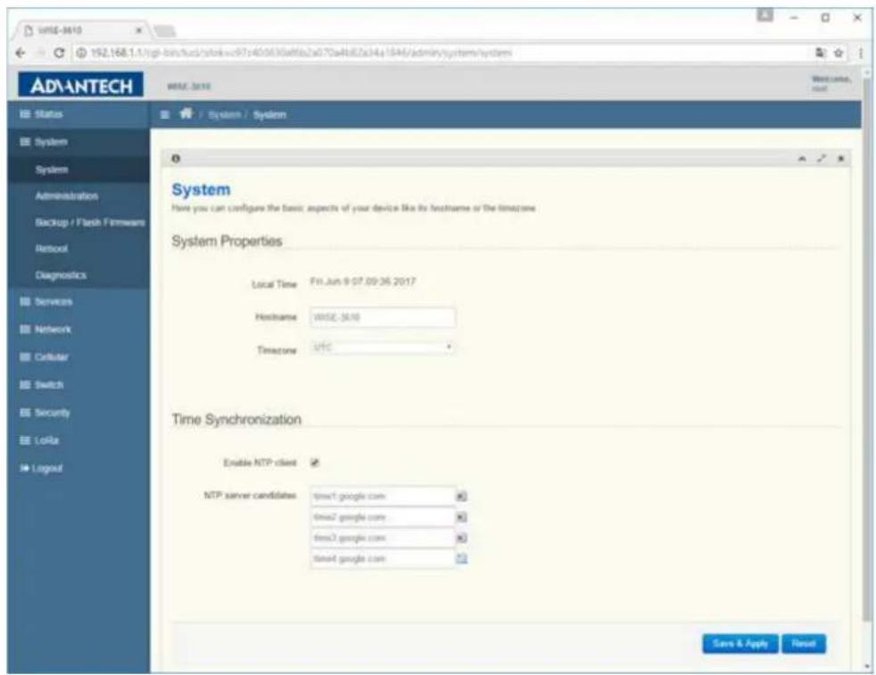
3.7 System
Visit System -> System to manage hostname and time setting of LoRa gateway.
3.7.1 Local Time
It will display the time status of LoRa gateway.
3.7.2 Hostname
Hostname of this LoRa gateway.
3.7.3 Timezone
Timezone setting for LoRa gateway.
3.7.4 Enable NTP client
To enable/disable SNTP client function.
3.7.5 NTP server candidates
LoRa gateway will perform time synchronization with SNTP server configured here.
3.8 Administration
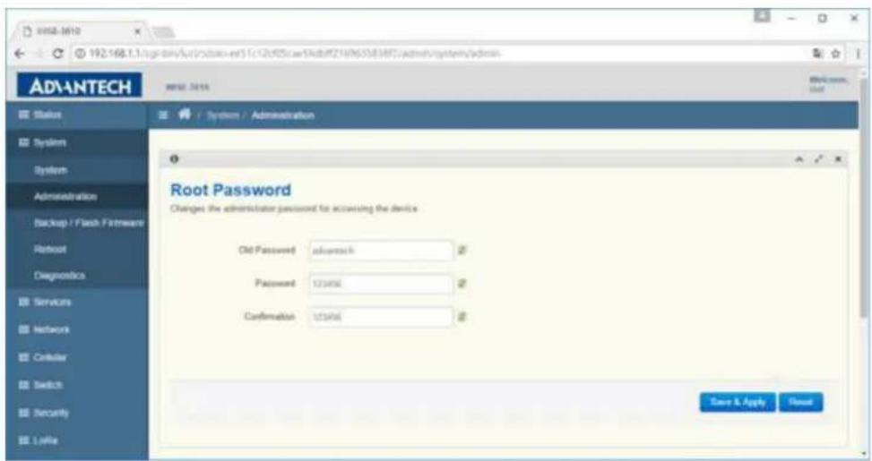
Visit System -> Administration to change the password of LoRa gateway.
3.8.1 Old Password
Input the original password to pass the authentication of changing password.
3.8.2 Password and Confirmation
Input the new password twice to double confirm the new password user want to change.
3.9 Backup / Flash Firmware
Visit System -> Backup / Flash Firmware to manage LoRa gateway configuration file and perform firmware upgrade.
3.9.1 Generate archive
To backup configuration file to host PC
3.9.2 Perform reset
To perform factory reset and all LoRa gateway configuration will be reset to factory default.
3.9.3 Upload archive
To restore configuration from host PC to LoRa gateway
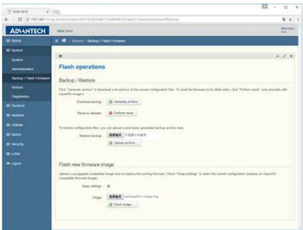
Visit System -> Backup / Flash Firmware to upgrade firmware of LoRa gateway.
3.9.4 Keep settings
User can choose to only perform firmware upgrade without reset the configuration. For formal use, we suggest to not keep settings due to new function may need to load new settings.
3.9.5 Flash image
To upgrade firmware, please choose firmware and press Flash image button
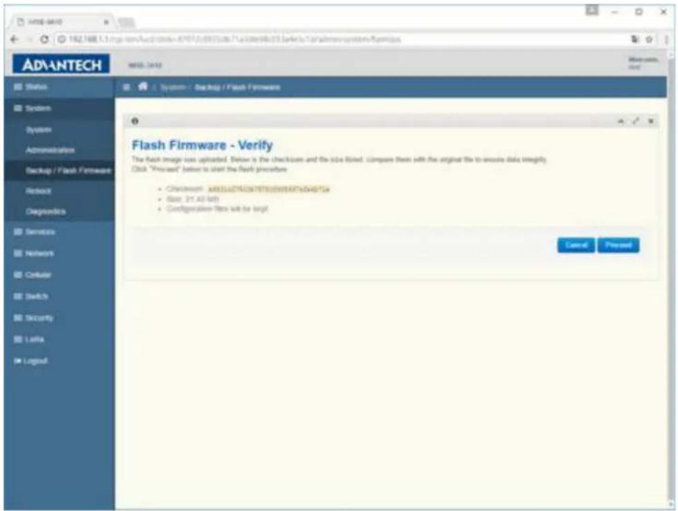
3.9.6 Flash Firmware -Verify
LoRa gateway will compute the MD5CHECKSUM for checking, and ask user to Proceed or Cancel.
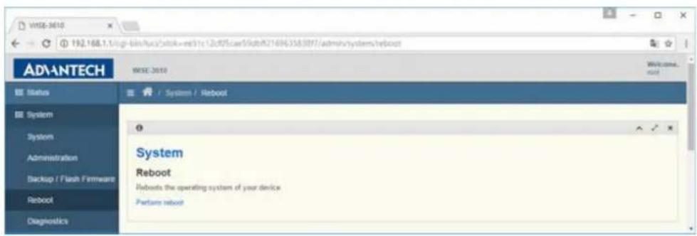
3.10 Reboot
Press 'Perform reboot' link to do rebooting.
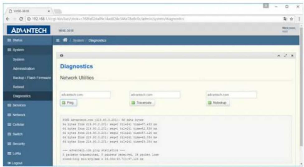
3.11 Diagnostics
Ping, Traceroute and Nslookup Diagnostics Tools.
3.12 Security
3.12.1 Remote Management
Visit Security -> Remote Management to open port on WAN zone interface.
3.12.1.1 HTTP / Port 80 (HTTPS / Port 443, SSH / Port 22, MQTT / Port 1883 or 8883 or 8884)
To enable/disable port access from WAN zone interface. The WAN zone interfaces include Ethernet WAN and 3G module. After enabling the port on WAN zone interface, external host can access related services running of LoRa gateway.
![192.168.13/cgr-ben/fun/cstow=07012c0035dts71a[dfe0dc03]safe0c1d/admav/fressual/te ADANTECH WISE 2019 Status System Services Network Cellular Switch Security Remote Management DMZ Port Forwarding MAC Filter HTTP/2TP IPSec LoRia Legend Remote Management Enabling Remote Management allows you to manage the router from anywhere on the Internet HTTP / Port 80 Disabled * HTTPS / Port 443 Disabled * SSH / Port 22 Disabled * MQTT / Port 1883 Disabled * MQTT / Port 8883 Disabled * MQTT / Port 8884 Disabled * Save & Apply Reset Remote Management](/content/2026/06/1150591/images/ad3b84caf83a8c8ab53acd1a02674a279ebe4a4e474879f355fcbc6270aaf722.jpg)
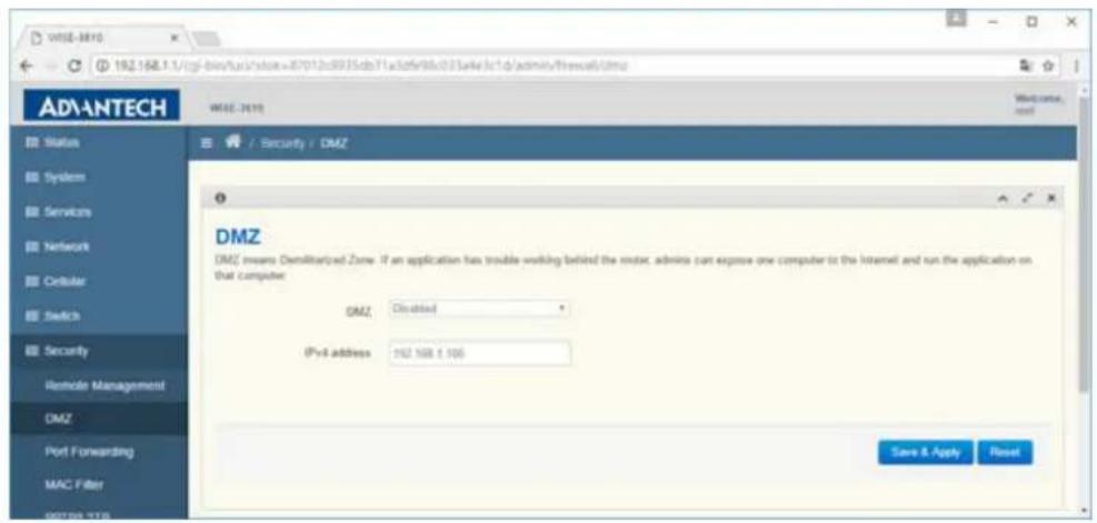
3.13 DMZ
Visit Security -> DMZ to enable/disable DMZ function.
3.13.1 DMZ
To enable/disable DMZ function.
3.13.2 IPv4 address
When DMZ is enabled, traffic come to the port of WAN zone will be forwarded to this private host.
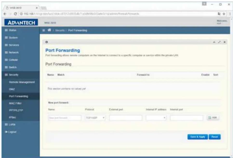
3.14 Port Forwarding
Visit Security -> Port Forwarding to add/delete port forwarding rule.
3.14.1 Port Forwarding
One port forwarding rule includes friendly rule name, Protocol, External Port, Internal IP address and Internal Port fields. The function of port forwarding is when traffic with configured protocol and port come to external port, LoRa gateway will forward traffic to internal IP and internal port. Port Forwarding and DMZ functions are similar. If user add a port forwarding rule to forward HTTP packets to private host PC, and then Remote Management host PC cannot surf Webpage of LoRa gateway.
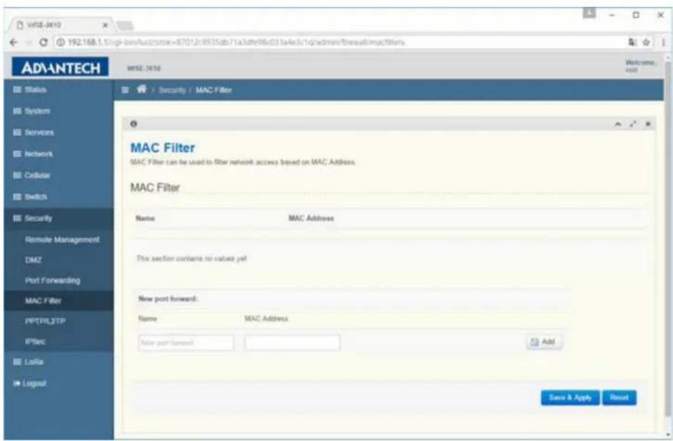
3.15 MAC Filter
Visit Security -> MAC filter to add/delete MAC filter rule.
3.15.1 MAC Filter
One MAC filter rule includes friendly rule name and MAC address. The function of MAC filter is to drop packet with configured source MAC address.
3.16 PPTP/L2TP
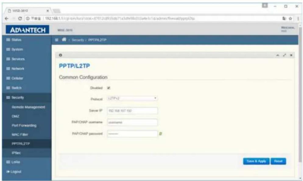
Visit Security -> PPTP/L2TP to enable/disable PPTP/L2TP function.
3.16.1 Disabled
By default PPTP/L2TP are disabled. To enable PPTP/L2TP function, user need to uncheck this item.
3.16.2 Protocol
User can choose PPTP or L2TP according to requirement.
3.16.3 Server IP
The PPTP/L2TP server that LoRa gateway purpose to connect.
3.16.4 PAP/CHAP username and PAP/CHAP password
The account to login to PPTP/L2TP server.
3.17 IPSec
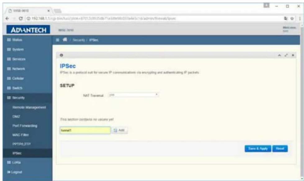
Visit Security -> IPSec to configure IPSec tunnel settings.
3.17.1 NAT Traversal
To enable/disable IPSec NAT Traversal function.
3.17.2 Add button
Introduce tunnel name and press add button to add a IPSec tunnel configuration template.
3.17.3 IKEv1/IKEv2
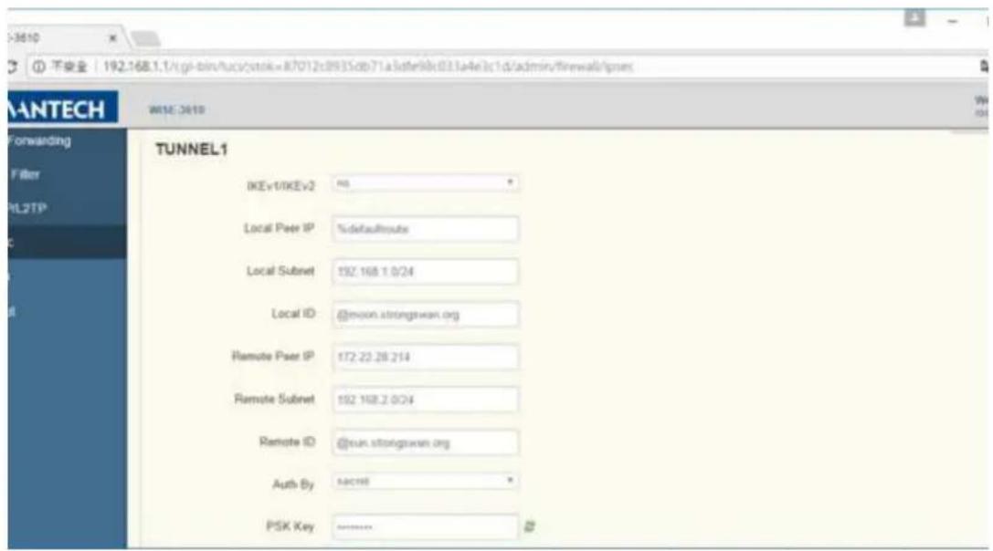
(1) permit: signify no IKEv2 should be transmitted, but will be accepted if peer sites initiate with IKEv2
(2) no: signify only use IKEv1, and no IKEv2 negotiation will be transmitted or accepted
(3) yes: signify allow IKEv1 and IKEv2, and use IKEv2 to start the negotiate by default
(4) insist: signify only IKEv2 is allowed, and IKEv1 will be rejected
3.17.4 Local Peer IP
The outgoing IP address of LoRa gateway. It will automatically detect if %defaultroute is configured.
3.17.5 Local Subnet
The private subnet behind the LoRa gateway, and the format is IP/mask length.
3.17.6 Local ID
The identify of LoRa gateway for IKE negotiation.
3.17.7 Remote Peer IP
The peer side IP address for IPSec tunnel.
3.17.8 Remote Subnet
The private subnet behind the peer side for IPSec tunnel.
3.17.9 Remote ID
The identify of peer side for IKE negotiation.
3.17.10 Auth By
(1) secret: pre-shared key combined with 4.6.11
(2) rsasig: RSA signature combined with 4.6.12\~4.6.15
3.17.11PSK Key
Pre-shared key for IPSec tunnel
3.17.12CA
Root CA Certificate
3.17.13 Local Certificate
The certificate of LoRa gateway for IKE negotiation.
3.17.14 Local Key
The private key of LoRa gateway for IKE negotiation.
3.17.15 Remote Certificate
The certificate of peer site for IKE negotiation.
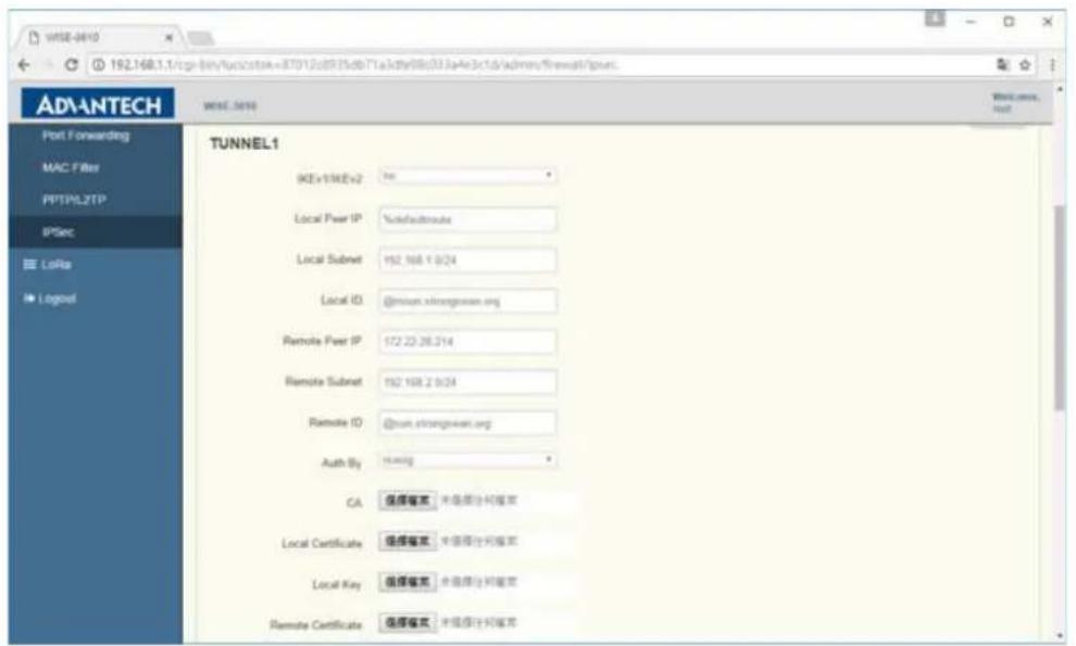
3.17.16IKE Algorithms
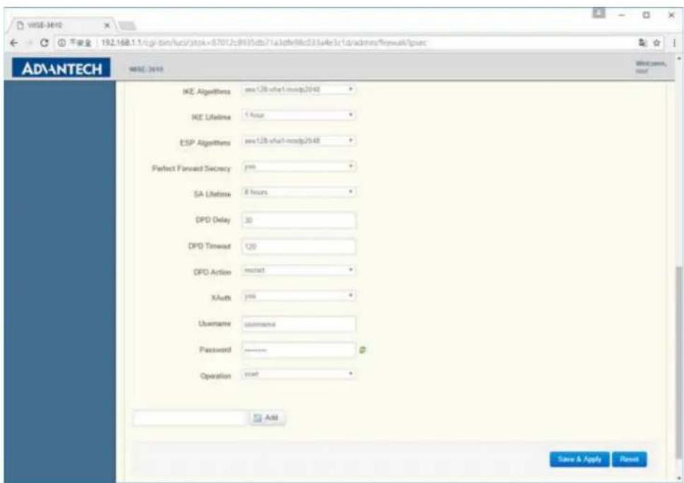
The security parameters for IKE phrase 1 negotiation. It supports following combination: 3des-md5-modp1024, 3des-md5-modp2048, 3des-sha1-modp1024, 3des-sha1-modp2048, aes128-md5-modp1024, aes128-md5-modp2048, aes128-sha1-modp1024, aes128-sha1-modp2048, aes256-sha1-dh22, aes256-sha1-dh23, aes256-sha1-dh24.
3.17.17IKE Lifetime
The lifetime of IKE phrase 1 negotiation. Before it is timeout, the IKE phrase 1 will be re-negotiated.
3.17.18 ESP Algorithm
The security parameters for IKE phrase 2 negotiation. It supports following combination: 3des-md5-modp1024, 3des-md5-modp2048, 3des-sha1-modp1024, 3des-sha1-modp2048, aes128-md5-modp1024, aes128-md5-modp2048, aes128-sha1-modp1024, aes128-sha1-modp2048, aes256-sha1-dh22, aes256-sha1-dh23, aes256-sha1-dh24.
3.17.19 Perfect Forward Secret
Perfect Forward Secret security feature for IKE negotiation.
3.17.20SA Lifetime
The lifetime of IKE phrase 2 negotiation. Before it is timeout, the IKE phrase 2 will be re-negotiated.
3.17.21 DPD Delay
The delay in seconds between Dead Peer Detection keepalives (R_U_THERE, R_U_THERE_ACK).
3.17.22DPD Timeout
The length of time in seconds that there are no DPD keepalives and no traffic. After this time period, DPD action will be performed.
3.17.23DPD Action
(1) hold: keep the security parameters in LoRa gateway
(2) clear: clear the security parameters in LoRa gateway
(3) restart: immediately to re-negotiate the security parameters
3.17.24XAuth
(1) no: disable XAuth authentication option
(2) yes: enable XAuth authentication option
3.17.25Username
The username for XAuth
3.17.26Password
The password for XAuth
3.17.27Operation
(1) start: the IKE will be initiated for this tunnel when LoRa gateway is bootup
(2) ignore: the IKE will not be initiated for this tunnel when LoRa gateway is bootup
3.18 Dynamic DNS
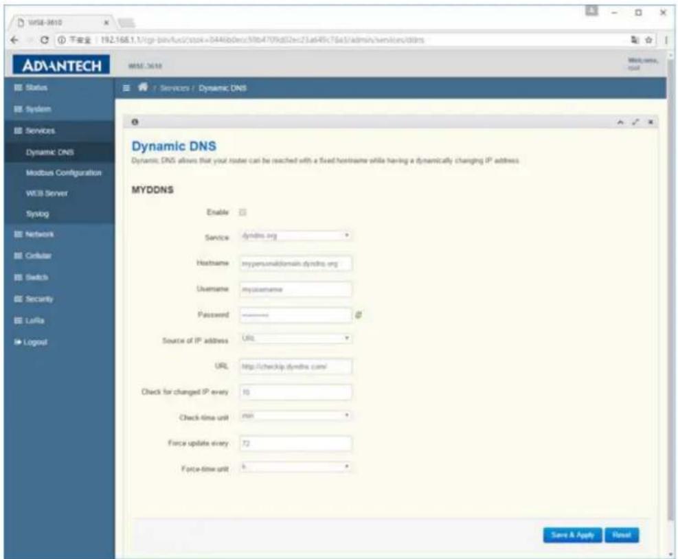
3.18.1 Enable
To enable/disable DDNS function.
3.18.2 Service
To choose the DDNS provider profile.
3.18.3 Hostname
The hostname is used to registered to DDNS provider for domain name query.
3.18.4 Username
The username is used to registered to DDNS provider.
3.18.5 Password
The password is used to registered to DDNS provider.
3.18.6 Source of IP address
The source IP address used to register to DDNS provider.
(1) network: choose IP on specific network
(2) URL: detect the current local IP from specified website. If LoRa gateway is behind a NAT, input the WEB URL that can report the external IP address of NAT router
3.18.7 Network
User can choose IP on wan, Ian or cellular interface
3.18.8 URL
The correct URL might depend on the DDNS provider being used, the sample format should be http://checkip.dyndns.org
3.18.9 Check for changed IP every and Check-time unit
The unit of time to check if IP address is changed in LoRa gateway.
3.18.10 Force update every and Force-time unit
The unit of time, LoRa gateway try to update the registered information.
3.19 Modbus Configuration
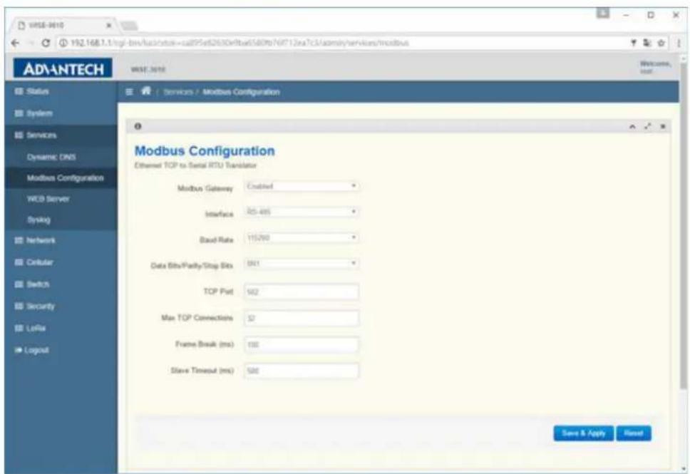
3.19.1 Modbus Gateway
To enable/disable Modbus TCP to Modbus serial RTU function.
3.19.2 Interface
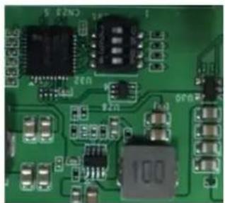
There are 3 kinds of modes LoRa gateway supported. The configuration of hardware and software must be matched to work properly.
RS-232(1000)
RS-422(1100)
RS-485(0100)
natural_image
Close-up of a green printed circuit board with various electronic components and traces (no readable text or symbols)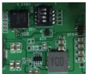
natural_image
Close-up of a green printed circuit board with various electronic components and connectors (no readable text or symbols)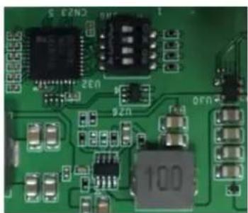
natural_image
Close-up of a green printed circuit board with various electronic components and connectors (no readable text or symbols)3.19.3 Baud Rate
LoRa gateway support following baud rate to communicate with RTU device: 9600, 12000, 14400, 19200, 38400, 57600, 115200.
3.19.4 Data Bits/Parity/Stop Bits
LoRa gateway support following data bits/parity/stop bits combinations: 8N1, 8O1, 8E1, 8N2, 8O2, 8E2.
3.19.5 TCP Port
The TCP Port that Modbus gateway running on LoRa gateway.
3.19.6 MAX TCP Connections
The maximum TCP connections allowed to connect to Modbus gateway.
The pause in milliseconds between requests.
3.19.8 Slave Timeout (ms)
The response wait time in milliseconds.
3.20 WEB Server
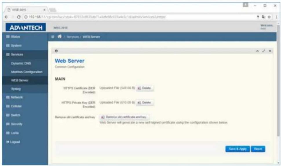
3.20.1 HTTPS Certificate
The https certificate for Web server. After delete, user can upload certificate prepared.
3.20.2 HTTPS Private Key
The https private key for Web server. After delete, user can upload private key prepared.
3.20.3 Remove old certificate and key
This button can remove certificate and key, and LoRa gateway will automatically generate certificate and key as bootup.
3.21 Syslog
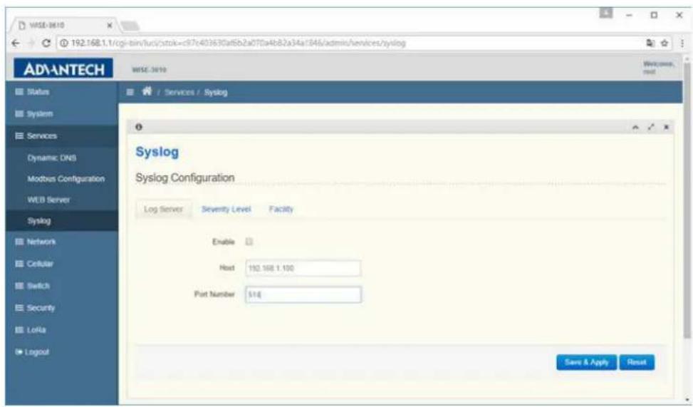
3.21.1 Enable
To enable/disable syslog sent to remote host PC.
3.21.2 Host
The IP address of remote host PC that run syslog server.
3.21.3 Port Number
The Port Number of remote host PC that run syslog server.
3.22 WIFI Status
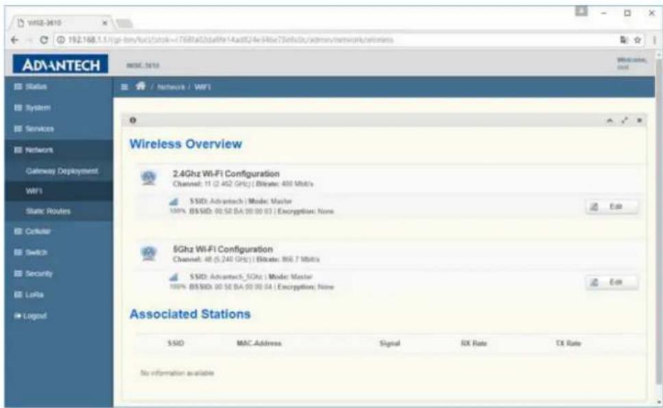
Visit Network -> WIFI to check WIFI function status.
3.22.1 Wireless Overview
It will show 2.4Ghz WIFI SSID and then 5Ghz WIFI SSID. The Edit button can get into detail WIFI setting page.
3.22.2 Associated Stations
It will display the associated WIFI stations including 2.4Ghz and 5Ghz WIFI stations.
3.23 WIFI Configuration
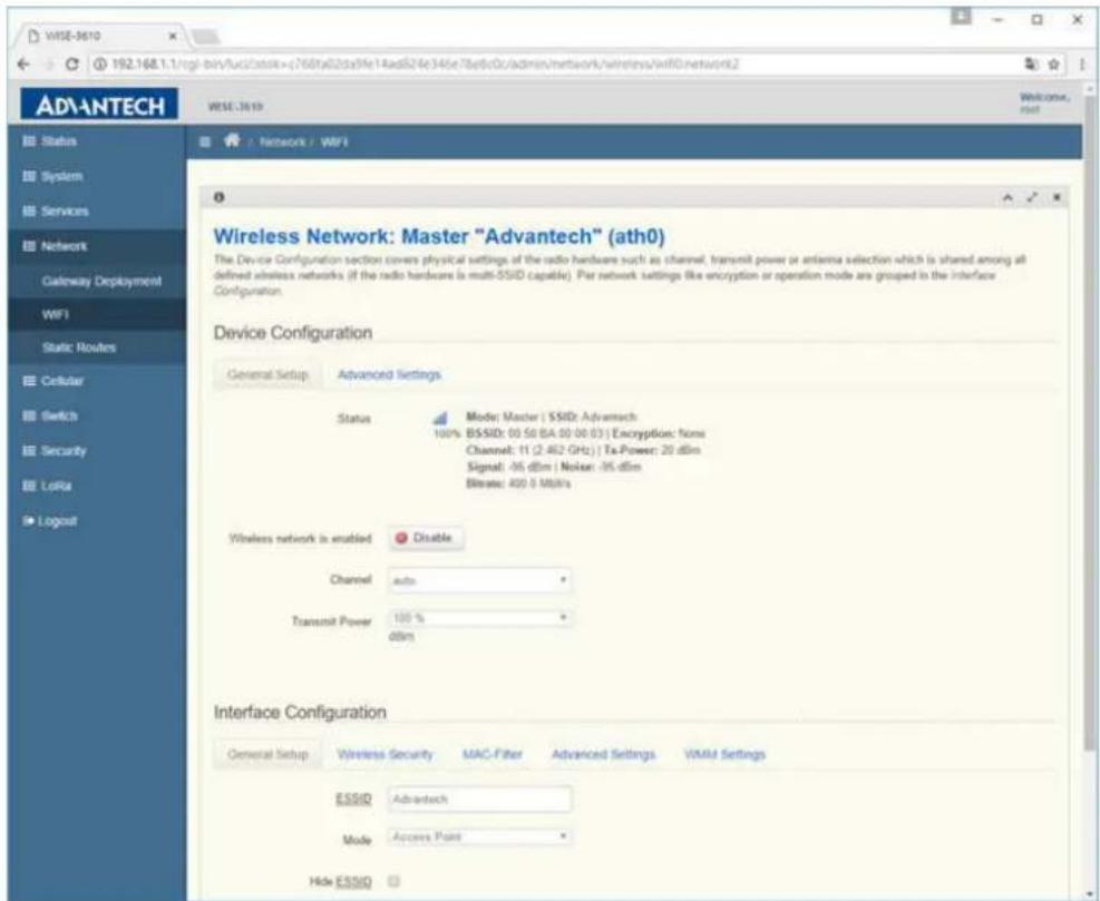
Visit Network -> WIFI -> Edit BUTTON to check or modify general WIFI function.
3.23.1 Wireless network is enabled
To enable/disable the WIFI SSID instance.
3.23.2 Channel
User can choose the desired channel or leave it auto to automatically selection.
3.23.3 Transmit Power
The maximum power is 20dbm mapped to 100%, and user can lower down the transmission power.
3.23.4 ESSID
The SSID for this wireless interface.
3.23.5 Mode
User can configure this SSID to be AP, Client or WDS-AP, WDS-Client.
3.23.6 Hide ESSID
User can choose to hide SSID explored by clients.
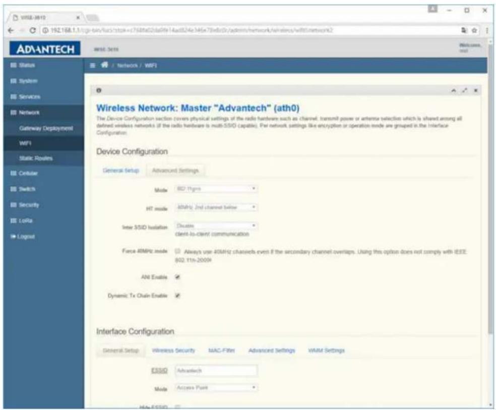
Visit Network -> WIFI -> Edit BUTTON -> Device Configuration -> Advanced Settings TAB to check or modify advance settings of device level.
3.23.7 Mode
The operating mode for WIFI interface. It supports auto, 802.11b, 802.11g, 802.11g+n for 2.4Ghz band and auto, 802.11a, 802.11a+n and 802.11ac for 5GHz band.
3.23.8 HT Mode
The channel bandwidth for WIFI device. It supports 20MHz, 40MHz 2nd channel below, 40MHz 2nd channel above, and 40MHz channel for 2.4Ghz band and 20MHz, 40MHz 2nd channel below, 40MHz 2nd channel above, 40MHz channel and 80MHz channel for 5GHz band.
3.23.9 Inter SSID Isolation
WIFI station to station communication between different SSID.
3.23.10 Force 40MHz mode
Force to use 40MHz channel bandwidth. To enable it will be not compatible with IEEE 802.11n-2009, and 20MHz client cannot associate to device.
3.23.11 ANI Enable
To enable/disable hardware level automatically noise immunity.
3.23.12 Dynamic Tx Chain Enable
To enable/disable chip vendor version of efficient transmission.
Visit Network -> WIFI -> Edit BUTTON -> Interface Configuration -> Wireless Security TAB to check or modify security settings of interface level.
3.23.13Encryption
The WIFI security settings. It supports No Encryption, WEP Open System, WEP Shared Key, WEP Mixed, WPA-PSK, WPA2-PSK, WPA-PSK/WPA2-PSK Mixed Mode, WPA-EAP, and WPA2-EAP.
3.23.14 Used Key Slot / Key#1 / Key#2 / Key#3 / Key#4
The security sub items when WEP is chosen. The Used Key Slot indicate which key is used for encryption, and user can introduce 4 keys in system.
3.23.15 Cipher / Key
The Cipher method and Key value for WPA-PSK, WPA2-PSK and WPA-PSK/WPA2-PSK Mixed Mode. The Cipher method supports auto, Force CCMP(AES), Force TKIP, Force TKIP and CCMP(AES).
3.23.16 Cipher / Radius-Authentication-Server(/Port/Secret) / Radius-Account-Enable / NAS ID
The RADIUS configuration for WPA-EAP and WPA2-EAP. The authentication and accounting will be performed on RADIUS server, and LoRa gateway works as authenticator.
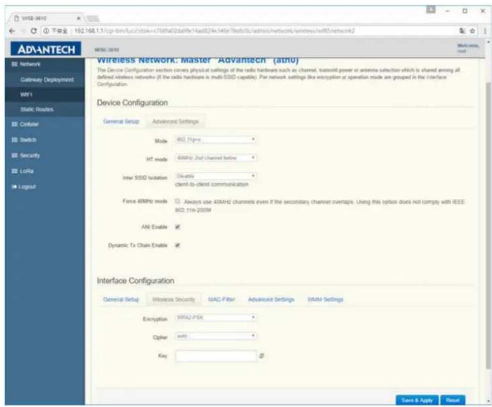
Visit Network -> WIFI -> Edit BUTTON -> Interface Configuration -> MAC Filter TAB to check or modify WIFI station MAC filter settings of interface level.
3.23.17 MAC-Address Filter
This is chip level MAC filter used to drop station traffic. It supports Allow listed only (white list) and Allow all except listed (black list).
3.23.18MAC-List
To input the MAC address of station that purpose to deny.
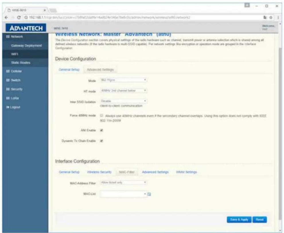
3.24 Static Routes
Visit Network -> Static Routes to manage static route of LoRa gateway. User can add host route or network route according to deployment environment.
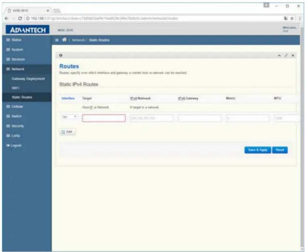
Switch
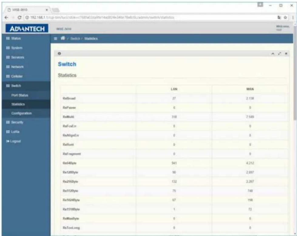
Visit Switch -> Port Status to check the LAN and WAN link status.
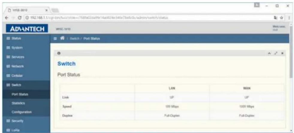
Visit Switch -> Statistics to check the LAN and WAN switch port counter status.
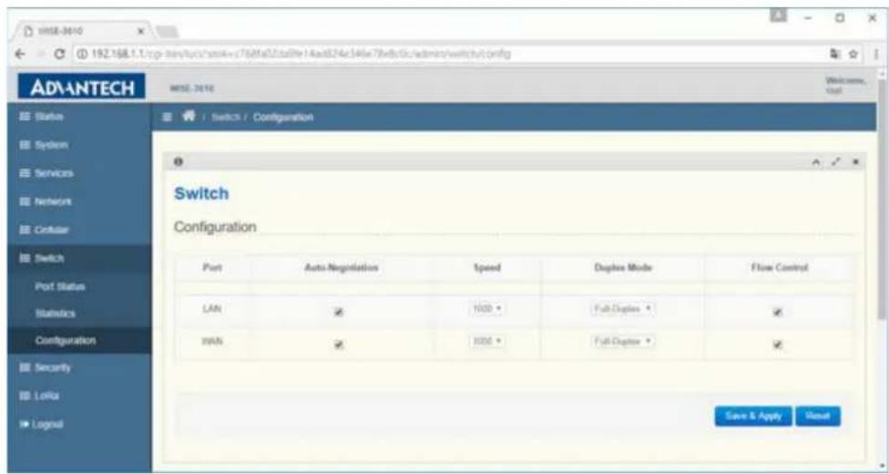
Visit Switch -> Configuration to manage the LAN and WAN switch port configuration. User can enable/disable Auto-Negotiation, Speed, Duplex Mode and Flow Control according the deployment environment.
3.25 Data and Charts
Visit WISE Manager -> Data and Charts to view the sensor data reported by all nodes.
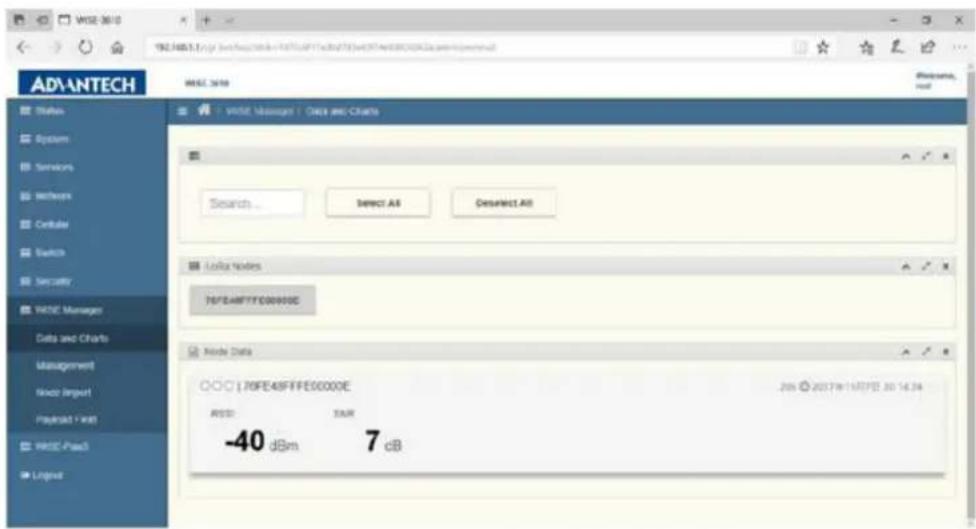
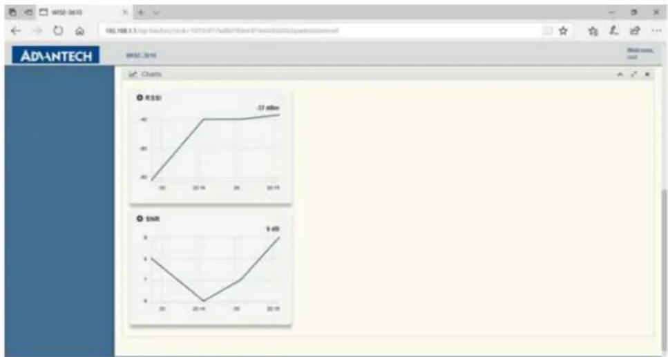
Click one of the three circles inside Node Data, Charts can be generated in the specified location: left, center, or right.
line
| Metric | Value | |--------|-------| | ROSE | -37.68mn | | SMR | 9.48mn |3.26 Management
Visit WISE Manager -> Management to manage the database of nodes and check the status of both gateway and nodes.
Management
The ID of Manager is automatically assigned, and its status is shown afterward. The values of status include 0 for "DOWN", 1 for "START_UP", and 2 for "IN_SERVICE". The ID of LoRa Gateway and Nodes are their EUI respectively, and their status are displayed afterward.
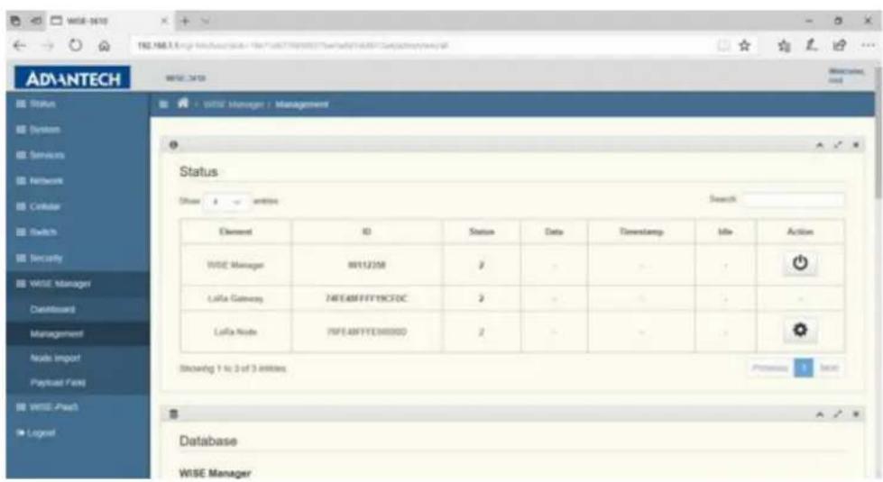
The "Action" button is used to restart WISE Manager. When clicked, the following dialog will popped up. Click "OK" to proceed, or "Cancel" to stop.
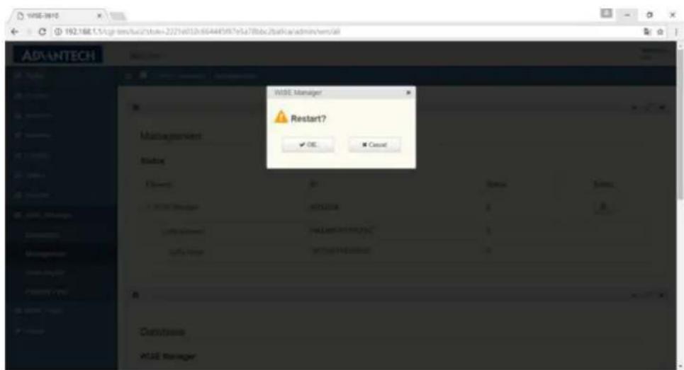
Note! Restart of "WISE Manager" is required after "Save & Apply" any settings of Management page.

Database
To manipulate Database of WISE Manager, LoRa Gateway, and LoRa Nodes, click the buttons under "Action".
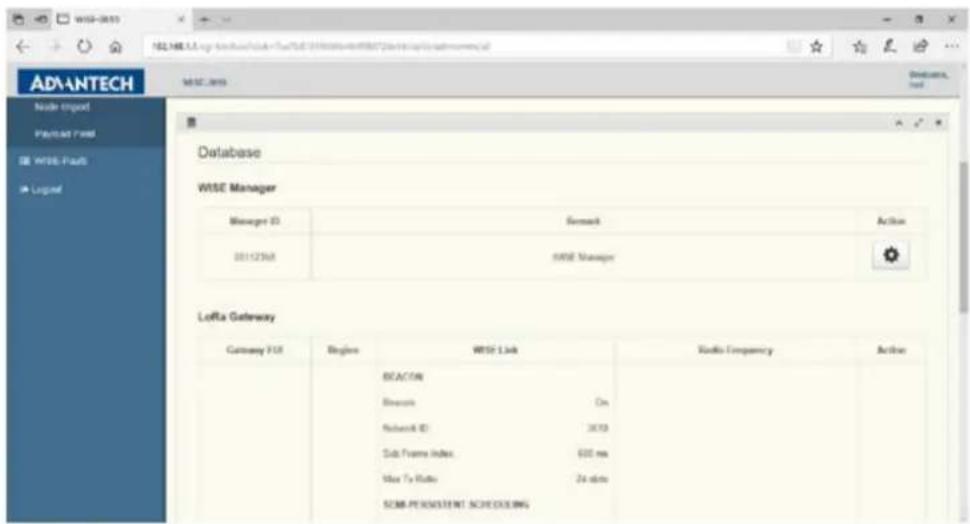
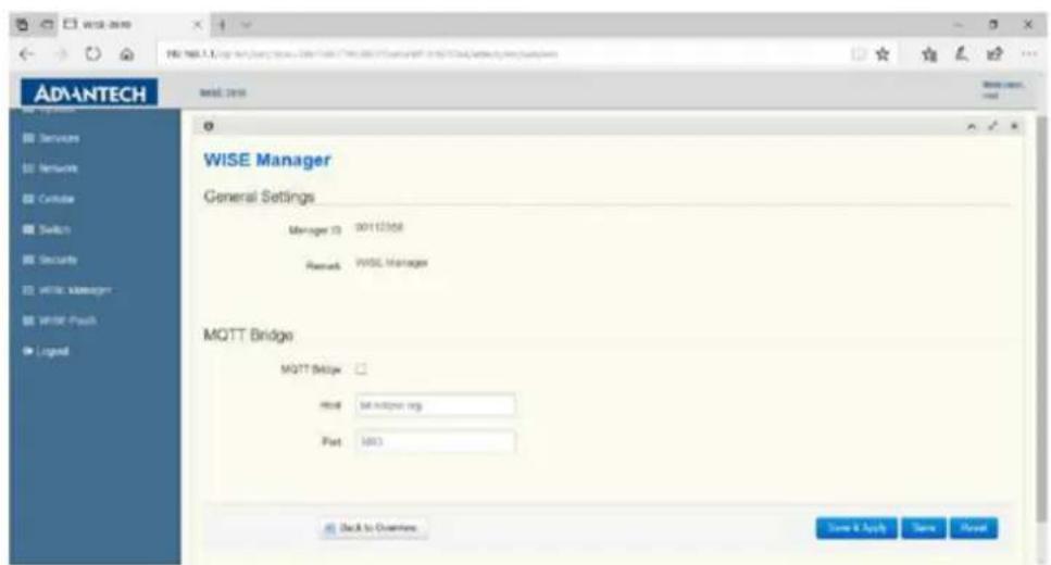
WISE Manager
This is an informative page about WISE Manager. MQTT Bridge is to set an external MQTT broker that the embedded MQTT broker can connect. Once enabled, all publication of status, including WISE Manaer's, LoRa Gateway's and Nodes', are forwarded to the external MQTT broker. Click "Back to Overview" after browsing the page.
LoRa Gateway
WISE-Link
This page is used to configure all parameters of WISE-Link. The following features can be enabled/or disabled:
"Beacon": On means WISE-Link 2.0. Off means WISE-Link 1.0
"Semi-Persistent Scheduling": On means Gateway allocates SPS sub-frames for Nodes. Off means Gateway only supports Lottery sub-frames.
"Multicasting": On means Gateway supports multicast to Nodes. Off means Gateway only supports uni-cast.
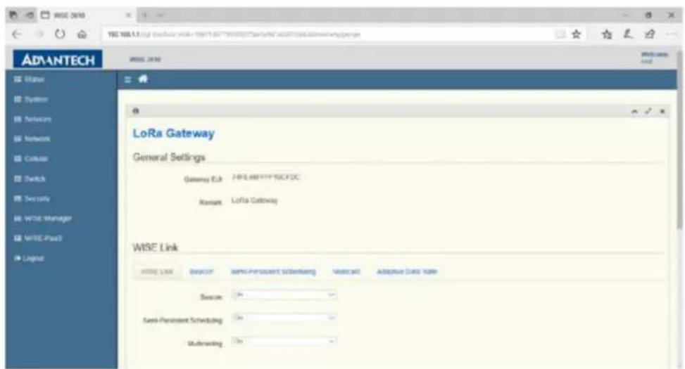
Then, configure parameters of each feature respectively.
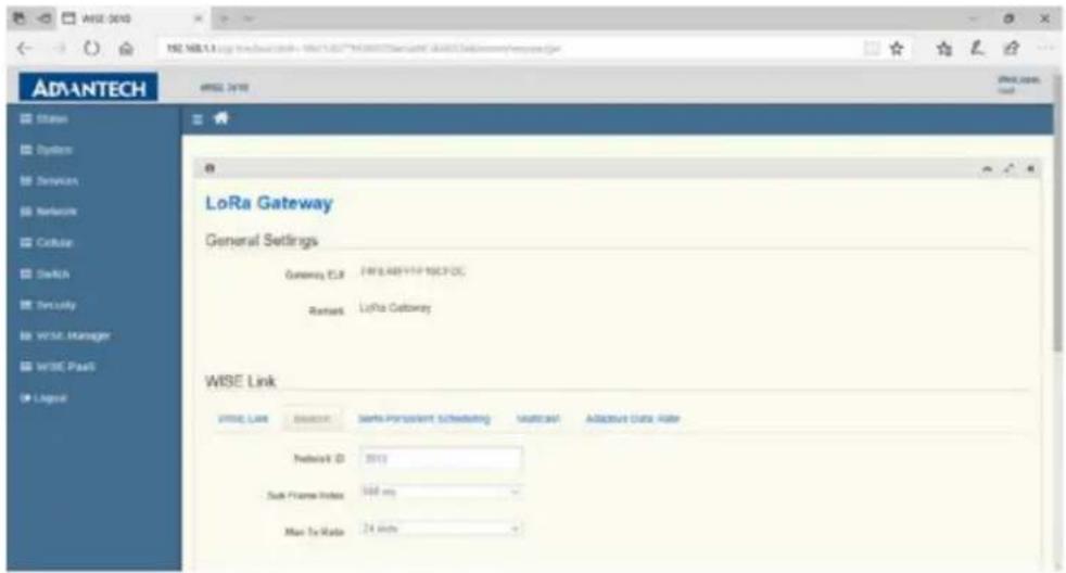
Beacon
"Network ID": 4-digits heximals, which identifies the network.
"Sub Frame Index": in terms of ms, which determines the maximum over-the-air time of an uplink packet.
"Max Tx Ratio": in terms of time slots, which determines the maximum over-the-air time of all downlink packets allowed within a TTI.
Note! Each time slot is 50 ms, and each TTI is 2400 ms.

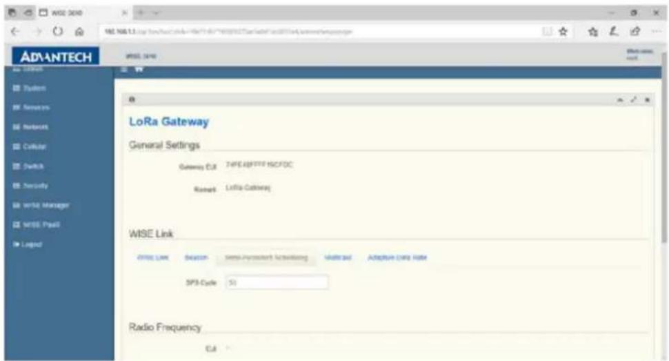
Semi-Persistent Scheduling
"SPS Cycle": in terms of TTI if the value is less or equal to 64, otherwise in terms of 64 TTIs, determines the cycle time of SPS sub-frames allocated to a specific node. For example, 24 means 24 TTIs, around 60 (=24*2.5) seconds, and 65 means 2 (65-63) * 64TTIs, around 320 (=2*64*2.5) seconds. The maximum allowed value is 1024.
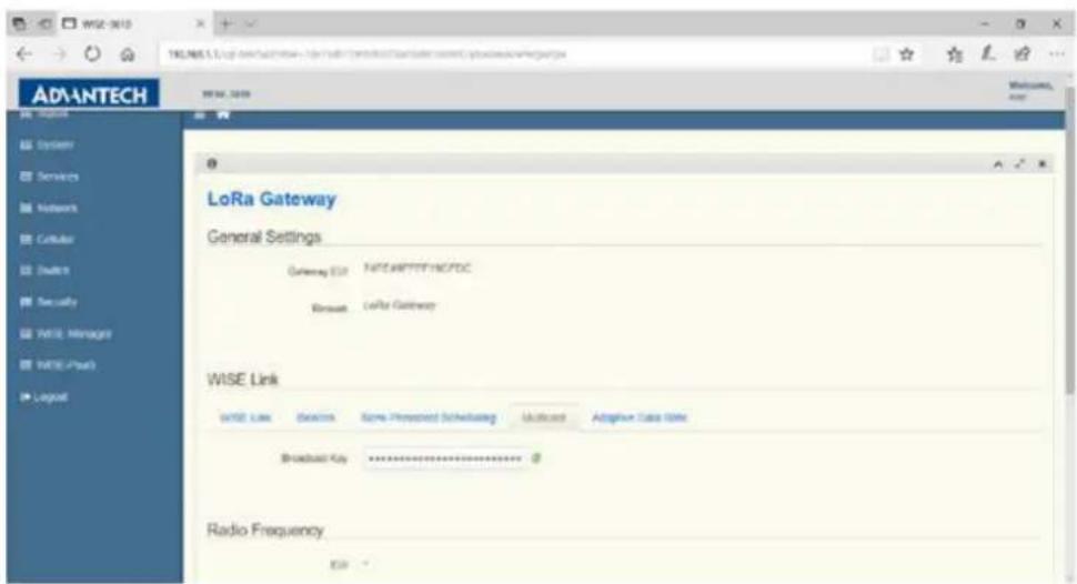
Multicast
"Broadcast Key": 32-digit heximals, which is used to encrypt/decrypt multicast packets.
"Use Nonce to generate multicast key": If checked, multicast keys will be derived from nonce, and used to encrypt/decrypt multicast packets.
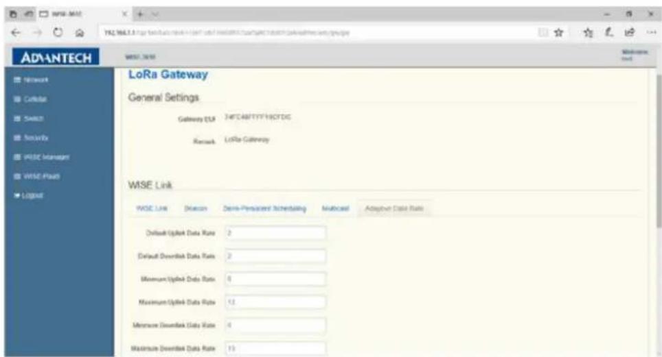
Adaptive Data Rate
"Default Uplink Data Rate": regional dependant. Allowed range for JP is 0\~5. Default 2.
"Default Downlink Data Rate": regional dependant. Allowed range for JP is 0\~5, with default 2.
"Minimum Uplink Data Rate": regional dependant. Default for JP is 0.
"Maximum Uplink Data Rate": regional dependant. Default for JP is 5.
"Minimum Downlink Data Rate": regional dependant. Default for JP is 0.
"Maximum Downlink Data Rate": regional dependant. Default for JP is 5.
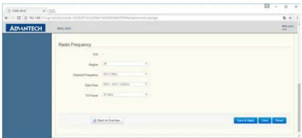
Radio Frequency
In case Beacon is On:
"Region": Select region to be used by Beacon.
"Channel Frequency": Select frequency to be used by Beacon. "Auto" means Gateway auto-selects the channel with the least RSSI.
"Data Rate": Fixed value per region.
"Tx Power": Downlink transmission power in unit of dBm.
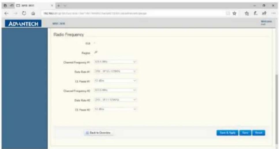
In case Beacon is Off:
"Region": Select region to be used by data.
"Channel Frequency #1": Select frequency to be used on channel 1.
"Data Rate #1": Select data rate to be used on channel 1.
"Tx power #1": Select downlink transmission power on channel 1.
"Channel Frequency #2": Select frequency to be used on channel 2.
"Data Rate #2": Select data rate to be used on channel 2.
"Tx power #2": Select downlink transmission power on channel 2.
Node
Add LoRa Node
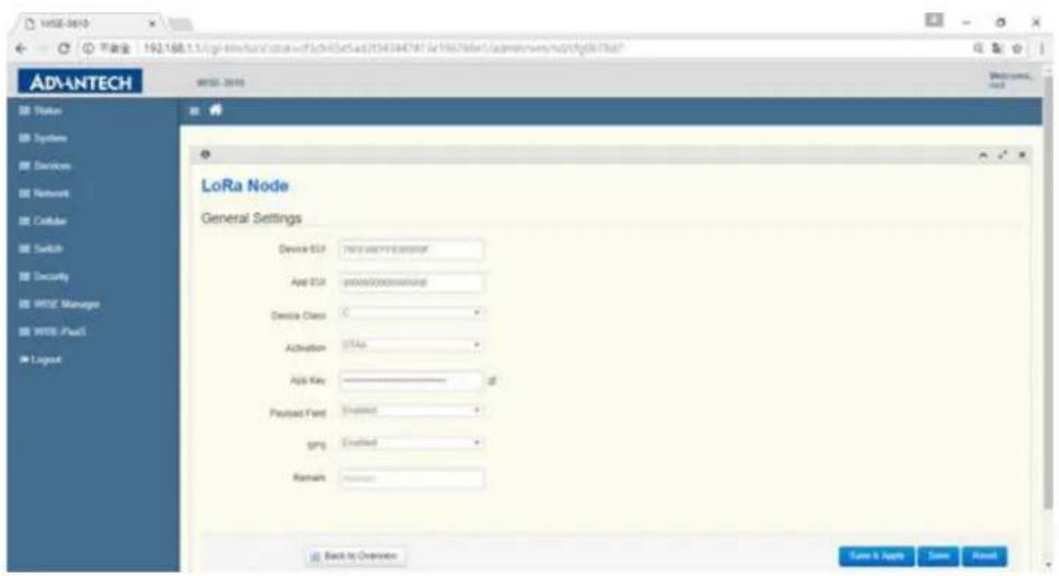
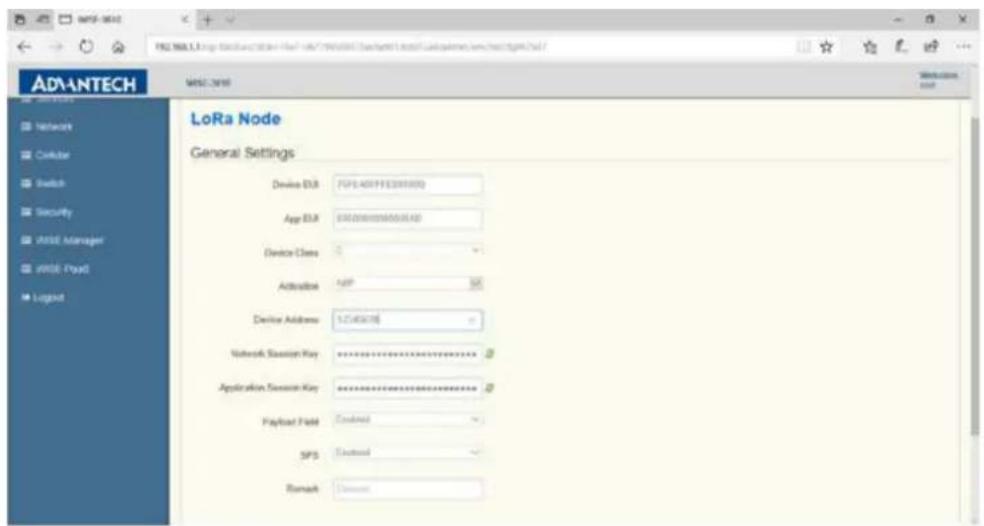
Depending on the "Activation" mode of nodes, different parameters are required. In case of OTAA,
"Device EUI": 16-digit heximals.
"App EUI": 8-digit heximals.
"Device Class": A stands for Class-A, and C stands for Class-C.
"Activation": OTAA
"App Key": 32-digit heximals.
"Payload Field": Enabled means data is encoded according to rules in WISE Manager->Payload Field. Disabled means data is in raw format.
"SPS": Enabled means SPS subframes are reserved for the node. Disabled means the node can use Lottery subframes only.
"Remark": used for decorating the node, up to 64 characters.
In case of ABP:
"Device EUI": 16-digit heximals.
"App EUI": 8-digit heximals.
"Device Class": A stands for class-A, and C stands for class-C.
"Activation": ABP
"Device Address": 8-digit heximals
"Network Session Key": 32-bit heximals
"Application Session Key": 32-bit heximals
"Payload Field": Enabled means data is encoded according to rules in WISE Manager->Payload Field. Disabled means data is in raw format.
"SPS": Enabled means SPS subframes are reserved for the node. Disabled means the node can use Lottery subframes only.
"Remark": used for decorating the node, up to 64 characters.
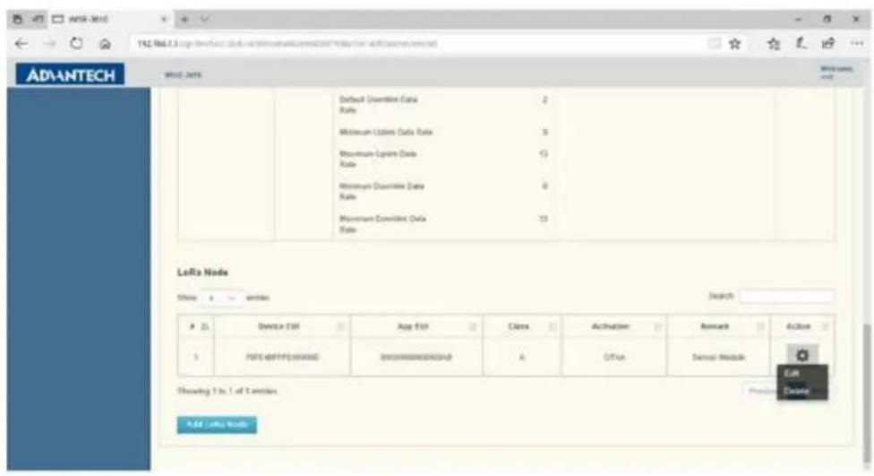
Edit/Delete Node
Click the circled button to edit an added node.
Delete
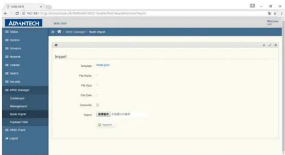
3.27 LoRa Node Import
Visit WISE Manageer -> Node Import to import node database. Click on the "Node.json" after "Template" to download the database template. The content of Node.json is as below:
[
    {
    "Metadata": ["DevEUI", "AppEUI", "Class", "ActMode", "AppKey", "PayloadField", "SpsConf", "Remark"],
    "Node": [
    ["76FE48FFFA000001", "00000000000000ab", "C", "OTAA", "00000000000000000000000000A1", "1", "1", "Node1"],
    ["76FE48FFFA000002", "00000000000000a b", "000000000000000a2", "1", "1", "Node2"]
    ]
},
{
    "Metadata": ["DevEUI", "AppEUI", "Class", "ActMode", "DevAddr", "NwkSKey", "AppSKey", "PayloadField", "SpsConf", "Remark"],
    "Node": [
    ["76FE48FFFA000003", "000000000000ab", "A", "ABP", "FA00003", "00000000000000a3", "1", "Node3"],
    ["76FE48FFFA00004", "0000000000aab", "C", "ABP", "FA00004", "1", "Node4"]
    ]
}
Two sections are enclosed in brackets: one for OTAA and the other for ABP nodes. Preserve the content of "Metadata", and replace the content inside "Node" with those nodes you have. Click "Select File" to select the edited data base, and then click "Append" to append the content into the current node database. Or, click "Overwrite" if you'd like overwrite the current database.
3.28 Payload Field
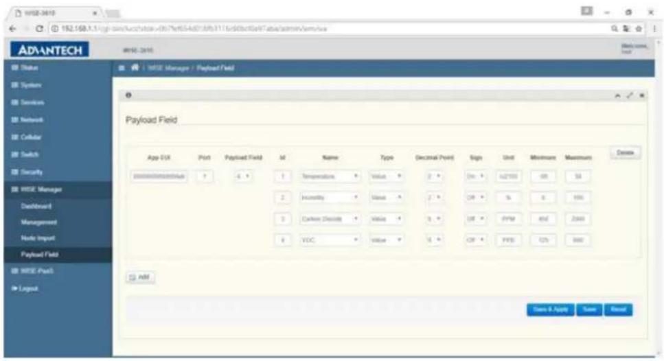
Visit WISE Manager -> Payload Field to define the format of sensor data. At most 4 sensor data can be encapsulated inside a payload field. Each payload field can be distinguished by Application EUI and Port.
"Application EUI": 16-digit heximals.
"Port": LoRa port number. Valid range is 0 to 223.
"Payload Field": Number of data formats, 1\~4.
"Id": Id of data.
"Name": Name of sensor type. Select "Custom" if there are no matched sensor type, and enter the proper name manually.
"Type": Type of data format, including "Raw", "Value", "String", "Boolean" and "GPS".
"Decimal Point": Factorization of data. 0 means no factorization.
"Sign": Signation of data. On means positive and negative, and Off means positive only.
"Unit": Unit of data value. Enter unicode if necessary.
"Minimum": the lower bound of data value.
"Maximum": the upper bound of data value.
Chapter 4
WISE-PaaS
4.1 Configuration
Visit WISE-PaaS to configure connection of WISE-PaaS/RMM.
4.1.1 Hostname
The domain name of WISE-PaaS/RMM server.
4.1.2 Port
TCP port number of WISE-PaaS/RMM Server.
Note! Username and Password are required to input.

Chapter 5
Advantech Services
This chapter introduces Advantech technical support and warranty policy for WISE-3610.
5.1 Contact Information
Below is the contact information for Advantech customer service.
| Region/Country Contact Information | |
| America 1-888-576-9688 | |
| Brazil 0800-770-5355 | |
| Mexico 01-800-467-2415 | |
| Europe (Toll Free) 00800-2426-8080 | |
| Singapore & SAP 65-64421000 | |
| Malaysia 1800-88-1809 | |
| Australia (Toll Free) 1300-308-531 | |
| China (Toll Free) | 800-810-0345800-810-8389Sales@advantech.com.cn |
| India (Toll Free) | 1-800-425-5071 |
| Japan (Toll Free) 0800-500-1055 | |
| Korea (Toll Free) | 080-363-9494 |
| 080-363-9495 | |
| Taiwan (Toll Free) | 0800-777-111 |
| Russia (Toll Free) | 8-800-555-01-50 |
On the other hand, you can reach our service team through below website, our technical support engineer will provide quick response once the form is filled out:
http://www.advantech.com.tw/contact/default.aspx?page=contact_form2&subject=Technical+Support
5.2 Global Service Policy
5.2.1 Warranty Policy
Below is the warranty policy of Advantech products:
5.2.1.1 Warranty Period
Advantech branded off-the-shelf products and 3rd party off-the-shelf products used to assemble Advantech Configure to Order products are entitled to a 2 years complete and prompt global warranty service. Product defect in design, materials, and workmanship, are covered from the date of shipment.
All customized products will by default carry a 15 months regional warranty service. The actual product warranty terms and conditions may vary based on sales contract.
All 3rd party products purchased separately will be covered by the original manufacturer's warranty and time period, and shall not exceed one year of coverage through Advantech.
5.2.1.2 Repairs under Warranty
It is possible to obtain a replacement (Cross-Shipment) during the first 30 days of the purchase, thru your original ADVANTECH supplier to arrange DOA replacement if the products were purchased directly from ADVANTECH and the product is DOA (Dead-on-Arrival). The DOA Cross-Shipment excludes any shipping damage, customized and/or build-to-order products.
For those products which are not DOA, the return fee to an authorized ADVANTECH repair facility will be at the customers' expense. The shipping fee for reconstructive products from ADVANTECH back to customers' sites will be at ADVANTECH's expense.
5.2.1.3 Exclusions from Warranty
The product is excluded from warranty if
The product has been found to be defective after expiry of the warranty period.
Warranty has been voided by removal or alternation of product or part identification labels.
The product has been misused, abused, or subjected to unauthorized disassembly/modification; placed in an unsuitable physical or operating environment; improperly maintained by the customer; or failure caused which ADVANTECH is not responsible whether by accident or other cause. Such conditions will be determined by ADVANTECH at its sole unfettered discretion.
The product is damaged beyond repair due to a natural disaster such as a lighting strike, flood, earthquake, etc.
■ Product updates/upgrades and tests upon the request of customers who are without warranty.
5.2.2 Repair Process
5.2.2.1 Obtaining an RMA Number
All returns from customers must be authorized with an ADVANTECH RMA (Return Merchandise Authorization) number. Any returns of defective units or parts without valid RMA numbers will not be accepted; they will be returned to the customer at the customer's cost without prior notice.
An RMA number is only an authorization for returning a product; it is not an approval for repair or replacement. When requesting an RMA number, please access ADVANTECH's RMA web site: http://erma.ADVANTECH.com.tw with an authorized user ID and password.
You must fill out basic product and customer information and describe the problems encountered in detail in "Problem D escription". Vague entries such as "does not work" and "failure" are not acceptable.
If you are uncertain about the cause of the problem, please contact ADVANTECH's Application Engineers (AE). They may be able to find a solution that does not require sending the product for repair.
The serial number of the whole set is required if only a key defective part is returned for repair. Otherwise, the case will be regarded as out-of-warranty.
5.2.2.2 Returning the Product for Repair
It's possible customers can save time and meet end-user requirements by returning defective products to an y authorized ADVANTECH repair facility without an extra cross-region charge. It is required to contact the local repair center before offering global repair service.
It is recommended to send cards without accessories (manuals, cables, etc.). Remove any unnecessary components from the card, such as CPU, DRAM, and CF Card. If you send all these parts back (because you believe they may be part of the problem), please note clearly that they are included. Otherwise, ADVANTECH is not responsible for any items not listed. Make sure the "Problem Description" is enclosed.
European Customers that are located outside European Community are requested to use UPS as the forwarding company. We strongly recommend adding a packing list to all shipments. Please prepare a shipment invoice according to the following guidelines to decrease goods clearance time:
- Give a low value to the product on the invoice, or additional charges will be levied by customs that will be borne by the sender.
- Add information "Invoice for customs purposes only with no commercial value" on the shipment invoice.
- Show RMA numbers, product serial numbers and warranty status on the shipment invoice.
- Add information about Country of origin of goods
In addition, please attach an invoice with RMA number to the carton, then write the RMA number on the outside of the carton and attach the packing slip to save handling time. Please also address the parts directly to the Service Department and mark the package "Attn. RMA Service Department".
All products must be returned in properly packed ESD material or anti-static bags. ADVANTECH reserves the right to return unrepaired items at the customer's cost if inappropriately packed.
Besides that, "Door-to-Door" transportation such as speed post is recommended for delivery, otherwise, the sender should bear additional charges such as clearance fees if Air-Cargo is adopted.
Should DOA cases fail, ADVANTECH will take full responsibility for the product and transportation charges. If the items are not DOA, but fail within warranty, the sender will bear the freight charges. For out-of-warranty cases, customers must cover the cost and take care of both outward and inward transportation.
5.2.2.3 Service Charges
The product is excluded from warranty if :
■ The product is repaired after expiry of the warranty period.
The product is tested or calibrated after expiry of the warranty period, and a No Problem Found (NPF) result is obtained.
The product, though repaired within the warranty period, has been misused, abused, or subjected to unauthorized disassembly/modification; placed in an unsuitable physical or operating environment; improperly maintained by the customer; or failure caused which ADVANTECH is not responsible whether by accident or other cause. Such conditions will be determined by ADVANTECH at its sole unfettered discretion.
The product is damaged beyond repair due to a natural disaster such as a lighting strike, flood, earthquake, etc.
■ Product updates and tests upon the request of customers who are without warranty.
If a product has been repaired by ADVANTECH, and within three months after such a repair the product requires another repair for the same problem, ADVANTECH will do this repair free of charge. However, such free repairs do not apply to products which have been misused, abused, or subjected to unauthorized disassembly/modification; placed in an unsuitable physical or operating environment; improperly maintained by the customer; or failure caused which ADVANTECH is not responsible whether by accident or other cause.
Please contact your nearest regional service center for detail service quotation.
Before we start out-of-warranty repairs, we will send you a pro forma invoice (P/I) with the repair charges. When you remit the funds, please reference the P/I number listed under "Our Ref". ADVANTECH reserves the right to deny repair services to customers that do not return the DOA unit or sign the P/I. Meanwhile, ADVANTECH will scrap defective products without prior notice if customers do not return the signed P/I within 3 months.
5.2.2.4 Repair Report
ADVANTECH returns each product with a "Repair Report" which shows the result of the repair. A "Repair Analysis Report" is also provided to customers upon request. If the defect is not caused by ADVANTECH design or manufacturing, customers will be charged US\60 or US\120 for in-warranty or out-of-warranty repair analysis reports respectively.
5.2.2.5 Custody of Products Submitted for Repair
ADVANTECH will retain custody of a product submitted for repair for one month while it is waiting for return of a signed P/I or payment (A/R). If the customer fails to respond within such period, ADVANTECH will close the case automatically. ADVANTECH will take reasonable measures to stay in proper contact with the customer during this one month period.
5.2.2.6 Shipping Back to Customer
The forwarding company for RMA returns from ADVANTECH to customers is selected by ADVANTECH. Per customer requirement, other express services can be adopted, such as UPS, FedEx and etc. The customer must bear the extra costs of such alternative shipment. If you require any special arrangements, please indicate this when shipping the product to us.
www.advantech.com
Please verify specifications before quoting. This guide is intended for reference purposes only.
All product specifications are subject to change without notice.
No part of this publication may be reproduced in any form or by any means, electronic, photocopying, recording or otherwise, without prior written permission of the publisher.
All brand and product names are trademarks or registered trademarks of their respective companies.
© Advantech Co., Ltd. 2019
- WISE-3610
- Wireless IoT LoRa Network Gateway
- Copyright
- Acknowledgements
- Product Warranty (2 years)
- Declaration of Conformity
- Federal Communication Commission Interference Statement
- Radiation Exposure Statement
- Industry Canada Statement
- Avertissement:
- - WLAN 5GHz:
- VCCI Certification
- Ordering Information
- Optional Accessories
- Safety Instructions
- Contents
- Chapter 1 General Introduction ......1
- Chapter 2 H/W Installation....5
- Chapter 3 Software Functionality......21
- Dynamic DNS.... 43
- Modbus Configuration 44
- WEB Server 46
- Syslog 46
- WIFI Status 47
- WIFI Configuration 48
- Static Routes....52
- Chapter 4 WISE-PaaS...... 65
- Chapter 5 Advantech Services.... 67
- Chapter 1
- General Introduction
- Introduction
- Product Features
- Mechanical Specifications
- Electrical Specifications
- Environmental Specifications
- Chapter 2
- H/W Installation
- Introduction
- WISE-3610 I/O Indication
- WISE-3610 Antenna Connectors
- LED Indication
- Reset Button
- Ethernet Connector (WAN, LAN)
- USB 3.0 Port
- COM Port
- Power Input Connector
- Micro SD Connector
- Micro SIM Connector
- On Board Connectors and Switches
- Connector and switch lists
- Connector Settings
- CN12 Micro SD Card Slot
- Micro SIM Card Primary Slot (CN28)
- Micro SIM Card Secondary Slot (CN27)
- Mini PCIE (CN5)
- Hardware switch (SW6)
- WWAN IPEX Connector (CN18)
- WISE-3610 Hardware Installation
- Mounting Assembly Method
- Enable WWAN feature with hardware installation
- Chapter 3
- Software Functionality
- WEB GUI Login
- Gateway Deployment Function Comparison
- Gateway Deployment (WAN)
- NorthBound
- Protocol
- DHCP Client
- Static IP
- PPPoE
- WAN / WAN Failover
- SouthBound
- LAN IPv4 address and netmask
- DHCP Server
- Start
- Limit
- Leasetime
- Gateway Deployment (WWAN)
- NorthBound
- SouthBound
- Cellular
- Enable
- SIM
- Cellular Status
- Gateway Deployment (2.4GHz WIFI)
- NorthBound
- Scan 2.4GHz AP Button
- Join Network Button
- WPA passphrase
- Gateway Deployment (5GHz WIFI)
- System
- Local Time
- Hostname
- Timezone
- Enable NTP client
- NTP server candidates
- Administration
- Old Password
- Password and Confirmation
- Backup / Flash Firmware
- Generate archive
- Perform reset
- Upload archive
- Keep settings
- Flash image
- Flash Firmware -Verify
- Reboot
- Diagnostics
- Security
- Remote Management
- HTTP / Port 80 (HTTPS / Port 443, SSH / Port 22, MQTT / Port 1883 or 8883 or 8884)
- DMZ
- DMZ
- IPv4 address
- Port Forwarding
- Port Forwarding
- MAC Filter
- MAC Filter
- PPTP/L2TP
- Disabled
- Protocol
- Server IP
- PAP/CHAP username and PAP/CHAP password
- IPSec
- NAT Traversal
- Add button
- IKEv1/IKEv2
- Local Peer IP
- Local Subnet
- Local ID
- Remote Peer IP
- Remote Subnet
- Remote ID
- Auth By
- 3.17.11PSK Key
- 3.17.12CA
- Local Certificate
- Local Key
- Remote Certificate
- 3.17.16IKE Algorithms
- 3.17.17IKE Lifetime
- ESP Algorithm
- Perfect Forward Secret
- 3.17.20SA Lifetime
- DPD Delay
- 3.17.22DPD Timeout
- 3.17.23DPD Action
- 3.17.24XAuth
- 3.17.25Username
- 3.17.26Password
- 3.17.27Operation
- Dynamic DNS
- Enable
- Service
- Hostname
- Username
- Password
- Source of IP address
- Network
- URL
- Check for changed IP every and Check-time unit
- Force update every and Force-time unit
- Modbus Configuration
- Modbus Gateway
- Interface
- Baud Rate
- Data Bits/Parity/Stop Bits
- TCP Port
- MAX TCP Connections
- Slave Timeout (ms)
- WEB Server
- HTTPS Certificate
- HTTPS Private Key
- Remove old certificate and key
- Syslog
- Enable
- Host
- Port Number
- WIFI Status
- Wireless Overview
- Associated Stations
- WIFI Configuration
- Wireless network is enabled
- Channel
- Transmit Power
- ESSID
- Mode
- Hide ESSID
- Mode
- HT Mode
- Inter SSID Isolation
- Force 40MHz mode
- ANI Enable
- Dynamic Tx Chain Enable
- 3.23.13Encryption
- Used Key Slot / Key#1 / Key#2 / Key#3 / Key#4
- Cipher / Key
- Cipher / Radius-Authentication-Server(/Port/Secret) / Radius-Account-Enable / NAS ID
- MAC-Address Filter
- 3.23.18MAC-List
- Static Routes
- Switch
- Data and Charts
- Management
- Management
- Database
- WISE Manager
- LoRa Gateway
- WISE-Link
- Beacon
- Semi-Persistent Scheduling
- Multicast
- Adaptive Data Rate
- Radio Frequency
- In case Beacon is On:
- In case Beacon is Off:
- Node
- Add LoRa Node
- In case of ABP:
- Edit/Delete Node
- Delete
- LoRa Node Import
- Payload Field
- Chapter 4
- Configuration
- Hostname
- Port
- Chapter 5
- Advantech Services
- Contact Information
- Global Service Policy
- Warranty Policy
- Warranty Period
- Repairs under Warranty
- Exclusions from Warranty
- Repair Process
- Obtaining an RMA Number
- Returning the Product for Repair
- Service Charges
- Repair Report
- Custody of Products Submitted for Repair
- Shipping Back to Customer
- www.advantech.com
Brand : Advantech
Model : WISE-3620
Category : Router