
X3-17-Thunder6 - Car Radio MTX Audio - Free user manual and instructions
Find the device manual for free X3-17-Thunder6 MTX Audio in PDF.

| Product Type | Complete Audio System Kit for Can-Am Maverick X3 |
| Brand | MTX Audio |
| Model | X3-17-Thunder6 |
| Components Included | AWMC3 Bluetooth Media Controller, X3-17-DK Dash Kit, MUDLEDC RGB Remote, MUD100.4 4-Channel Amplifier, MUD600-1 Mono Amplifier, X3-17-FS-L Front Lower Speaker Pods, X3-17-FS-U Front Upper Speaker Pods, X3-17-SW-D Driver Subwoofer Enclosure, X3-17-SW-P Passenger Subwoofer Enclosure, Wiring Harness, External Bass Control Knob |
| Speaker Configuration | 4x 4-inch Upper Dash Speakers, 4x 6.5-inch Lower Kick Panel Speakers, 2x 12-inch Subwoofers |
| RMS Power Handling (Speakers) | 50 Watts per Channel (Upper and Lower) |
| Peak Power Handling (Speakers) | 100 Watts per Channel |
| Subwoofer RMS Power | 300 Watts per Enclosure |
| Subwoofer Peak Power | 600 Watts per Enclosure |
| Frequency Response (Upper Speakers) | 75 Hz - 20 kHz |
| Frequency Response (Lower Speakers) | 70 Hz - 20 kHz |
| Frequency Response (Subwoofers) | 23 Hz - 130 Hz |
| Impedance | 4 Ohms (All Speakers and Subwoofers) |
| Sensitivity (Upper/Lower) | 85.6 dB (1W/1m) |
| Sensitivity (Subwoofers) | 84.4 dB (1W/1m) |
| Bluetooth Controller | AWMC3 All-Weather Bluetooth Media Controller with RGB Remote |
| Amplifier Type | MUD100.4 4-Channel and MUD600-1 Monoblock |
| Vehicle Compatibility | Can-Am Maverick X3 (2017-2021 models, see fit guide) |
| Mounting Location | Dash, Kick Panels, Under Seats |
| Warranty | 2-Year Limited Warranty |
| Care Instructions | Clean with mild soap and water; avoid harsh chemicals. Disconnect battery before installation. |
| Safety Notes | Disconnect battery before working. Ensure power wire is fused at battery connection. Use caution when drilling. |
| Spare Parts Availability | Contact MTX Audio or authorized dealers for replacement parts. |
Frequently Asked Questions - X3-17-Thunder6 MTX Audio
User questions about X3-17-Thunder6 MTX Audio
0 question about this device. Answer the ones you know or ask your own.
Ask a new question about this device
Download the instructions for your Car Radio in PDF format for free! Find your manual X3-17-Thunder6 - MTX Audio and take your electronic device back in hand. On this page are published all the documents necessary for the use of your device. X3-17-Thunder6 by MTX Audio.
USER MANUAL X3-17-Thunder6 MTX Audio
natural_image
Collection of various electronic devices and connectors, including a camera module, speaker modules, and cable bundles (no visible text or symbols)Thank You!
Congratulations and thank you for purchasing the MTX Audio X3-17-THUNDER6 audio system designed for the Can-Am™ Maverick X3. Our audio system will deliver ground pounding audio making you the party vehicle in any ride!
With a few basic hand tools in your trusty toolbox, you can have this installed in no time. So, what are you waiting for? It's time to get the rumble in your ride and go hit the trails! Oh, and congratulations on your purchase, thanks for your support and most importantly, enjoy the ultimate audio experience with MTX!
IN THE BOX
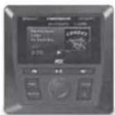
AWMC3
Bluetooth Media Controller
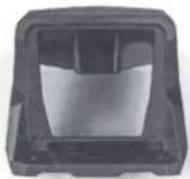
X3-17-DK
AWMC3 Dash Kit
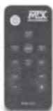
MUDLEDC
RGB Remote Control
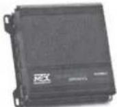
MUD100.4
4-Channel Amplifier
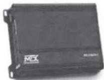
MUD600-1
Mono Block Amplifier
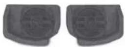
X3-17-FS-L
Front Speaker Kit
(Lower)
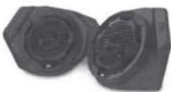
X3-17-FS-U
Front Speaker Kit (Upper)
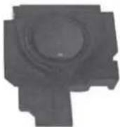
X3-17-SW-D
Subwoofer Kit (Driver Side)

X3-17-SW-P
Subwoofer Kit (Passenger Side)
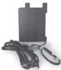
natural_image
Black rectangular electronic device with attached wires and a small black clip (no visible text or symbols)X3-17-CORE
Amplifier Bracket Kit and Wire Harness
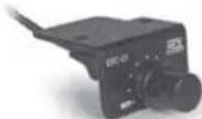
EBC-01
External Bass Control
Knob

natural_image
Close-up of a black, curved cable or wire with metallic leads (no text or symbols visible)1-10823
AWMC3 Amplifier
Harness
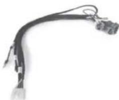
natural_image
Close-up of a black cable with attached connectors and wires (no text or symbols visible)1-10825
AWMC3 Speaker Harness
RECOMMENDED TOOLS
• T40 Torx with driver or drill
- Small flat blade or pin removal tool
• 19mm socket with extension and driver or drill
• 15mm socket with driver or drill
• 13mm socket with driver or drill
• 10mm socket with driver or drill
- 13mm wrench
- 10mm wrench
• 3mm Allen wrench - RGB option - heat gun, butane torch, or lighter
- Extra zip ties
INSTALL VIDEO
Please visit http://mitk.co/NLH or scan the QR code to view our installation video.

VEHICLE LAYOUT
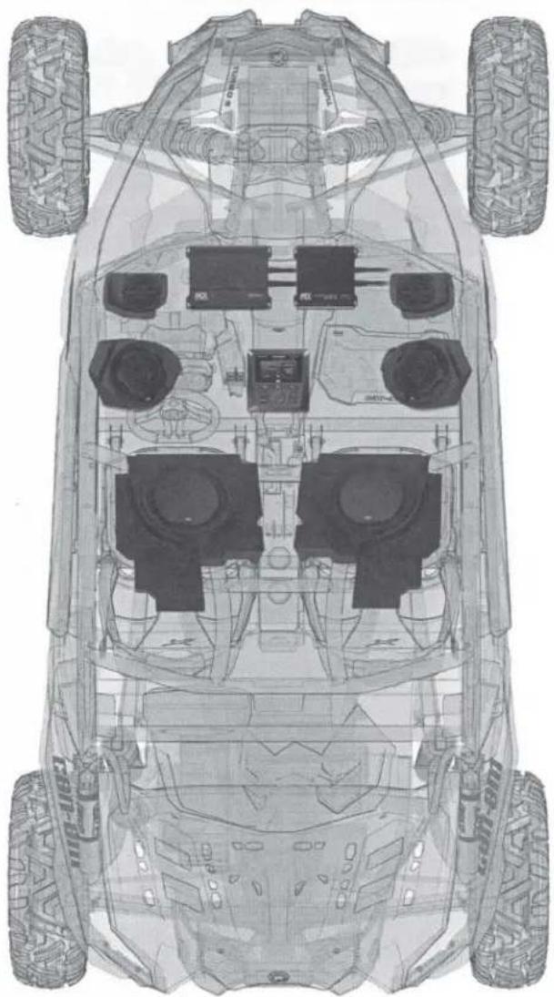
natural_image
Top-down technical line drawing of a vehicle chassis with four tires and front-mounted sensors (no text or symbols)WE'RE HERE TO HELP
We're here to help with any installation or technical support. Visit mtx.com to chat, call 1-800-225-5689 to speak with an MTX Technical Support representative, or visit youtube.com/user/MTXAudioUSA to view product videos.
DON'T FORGET TO REGISTER YOUR PRODUCT
Don't forget to register your new MTX Audio product. Visit mtx.com/productregistration or scan the QR code to the right.
Model #
Serial #
Dealer's Name
Date of Purchase

MAKE SURE TO READ THIS
Installation of the X3-17-THUNDER6 audio system requires a lot of vehicle disassembly. It is very important to return all hardware from which it came to insure the safety and longevity of the vehicle and audio system.
IMPORTANT NOTICE
Whenever working on the vehicle, it is recommended to disconnect the battery prior to starting work. Failure to do so may lead to a risk of electric shock or equipment damage. When connecting power and ground wires ensure that the red power wire is fused at the point where it is connected to the vehicle's battery. Failure to do so can result in damage to the vehicle if a short circuit develops between the vehicle connection point and the product.
MGX®
AUDIO
THANKS AGAIN!
Once you're done putting your new MTX Audio X3-17-THUNDER6 audio system to the test, and making all your friends jealous, be sure to find us online and let us know what you think. Leave a product review on the website, and connect with us over social media.
Let's Get Social
mtx.com

Like, Follow, & Subscribe
© 2021 MiTek Corporation. All rights reserved. MTX is a trademark of MiTek Corporation. All other trademarks are property of their respective owners. Designed and Engineered in the U.S.A. Due to continual product development, all specifications are subject to change without notice.
MTX Audio, 4545 East Baseline Rd. Phoenix, AZ 85042 U.S.A. 1-800-225-5689
MTX006499 RevA 4/21 • AW0015974 • 1-12420
MX® AUDIO
natural_image
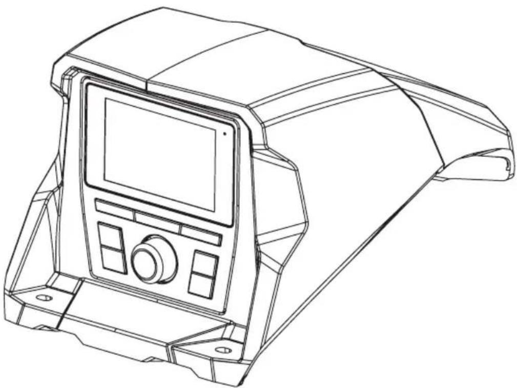
Line drawing of a mechanical device casing with control panel and mounting feet (no text or symbols)X3-17-DK
CAN-AM® MAVERICK X3 DASH KIT
OWNER'S MANUAL

THANK YOU
Thank you for making the AWESOME decision to purchase our Can-Am® Maverick X3 dash kit designed for use with the MTX Audio AWMC3 Bluetooth all-weather head unit. This easy to install dash kit is the perfect OEM fit solution for your Can-Am® Maverick X3. So, congratulations on your purchase, thanks for your support and most importantly, enjoy the ultimate audio experience with MTX!
WE'RE HERE TO HELP
We're here to help with any installation or technical support. Visit mtx.com to chat, call 1-800-225-5689 to speak with an MTX Technical Support representative, or visit youtube.com/user/MTXAudioUSA to view product videos.
DON'T FORGET TO REGISTER YOUR PRODUCT
Don't forget to register your new MTX Audio product. Visit mtx.com/productregistration or scan the QR code to the right.
Model # ____
Serial #
Dealer's Name
Date of Purchase

IMPORTANT NOTICE
Whenever working on the vehicle, it is recommended to disconnect the battery prior to starting work. Failure to do so may lead to a risk of electric shock or equipment damage.
When connecting power and ground wires ensure that the red power wire is fused at the point where it is connected to the vehicle's battery. Failure to do so can result in damage to the vehicle if a short circuit develops between the vehicle connection point and the product.

FIT GUIDE
Turbo / Max Turbo....2018 - 2019
Turbo R / Max Turbo R....2017 - 2019
X-DS Turbo 2017
X-RS Turbo R / Max X-RS Turbo R....2017 - 2019
X-DS Turbo R / Max X-DS Turbo R 2018 - 2019
X-MR Turbo 2019 - 2021
X-MR Turbo R....2019
X-RC Turbo 2019 - 2021
X-MC Turbo R....2019
DS Turbo / Max DS Turbo 2020 - 2021
RS Turbo 2020
DS Turbo R / Max DS Turbo R 2020 - 2021
Max DS Turbo RR 2020
RS Turbo R / Max RS Turbo R....2020 - 2021
X-RC Turbo RR 2020 - 2021
X-RS Turbo RR / Max X-RS Turbo RR....2020 - 2021
X-MR Turbo RR / Max X-MR Turbo RR 2020 - 2021
X-MS Turbo RR 2020
X-DS Turbo RR / Max X-DS Turbo RR 2020 - 2021
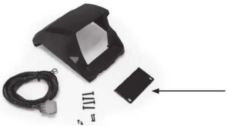
IN THE BOX
- Dash Kit
- Mounting Hardware
(1) Compression Plate
(2) Compression Plate Screws
(4) Shroud Screws
(2) Source Unit Screws
INSTALLATION TOOLS
The following is a list of suggested tools needed for installation:
- 1" Hole Saw
- Torx T8 Screwdriver
- Torx T20 Screwdriver
- Drill and 18 " Drill Bit
INSTALLATION
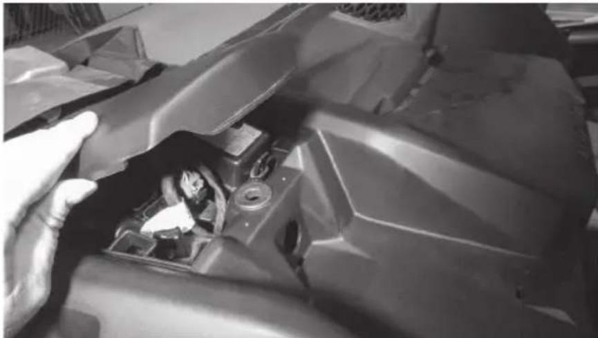
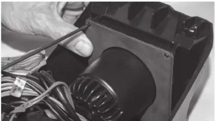
Step 1 - Remove the cover from top center of the dash.
natural_image
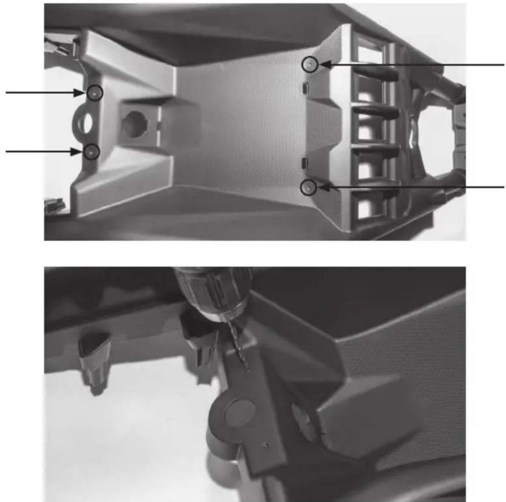
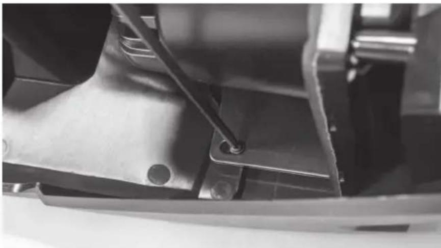
Close-up of a hand adjusting a damaged mechanical component, no visible text or symbolsStep 2 - Locate the four (4) dimples formed into the tray area on the top center dash. Two are located toward the front and two are at the rear under the cover that was just removed. Using a 18 " drill bit, drill through the dimples just enough to expose the existing boss located below. Caution: Drilling deeper can damage the bosses beneath and prevent proper installation of the dash kit.
natural_image
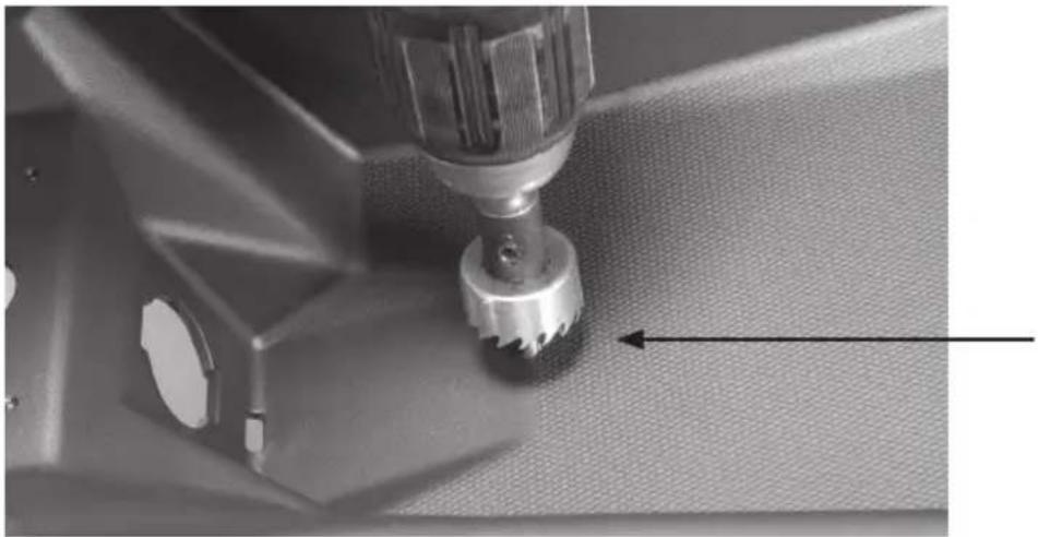
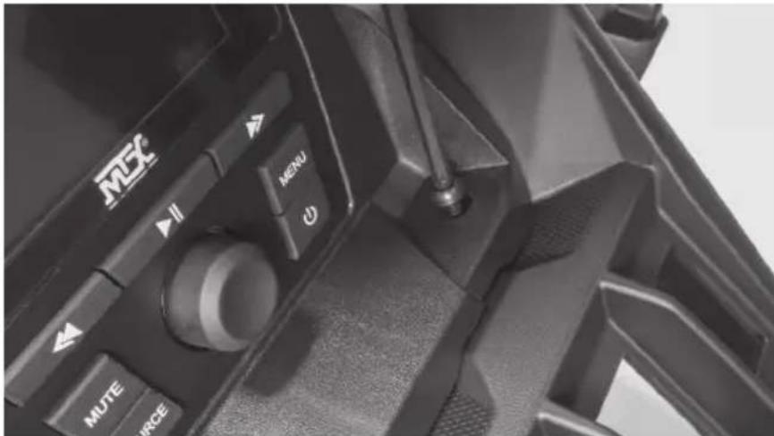
Two grayscale images showing internal mechanical components with no visible text or symbolsStep 3 - Using a 1" hole saw, drill a hole in the top of the dash to pass the wiring harness through. Our recommended location is indicated in the picture. Note: The 12-volt power port can be removed and used to pass the harness through the dash if you do not desire to drill a separate hole. This will require the removal of the center dash console panel to remove the power port.
natural_image
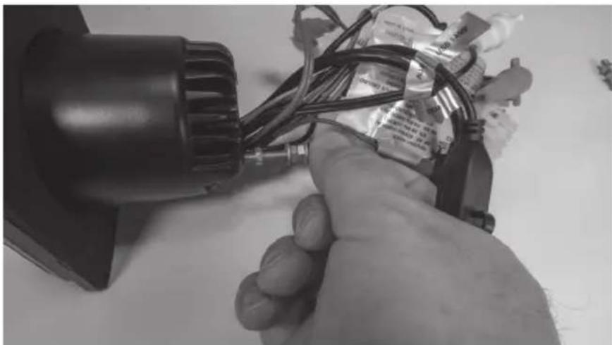
Close-up of a sewing machine needle stitching fabric, showing mechanical components and a tool (no text or symbols visible)Step 4 - Prepare the AWMC3 radio unit by removing the two (2) threaded studs from the back of the radio.
natural_image
Close-up of a hand holding a small electronic device with wires and components (no visible text or symbols)Step 5 - Locate the compression plate (shown) in the kit. Install it loosely as shown into the kit by inserting two (2) short screws included.
natural_image
Black plastic enclosure with attached cable and a small black rectangular component, no visible text or symbols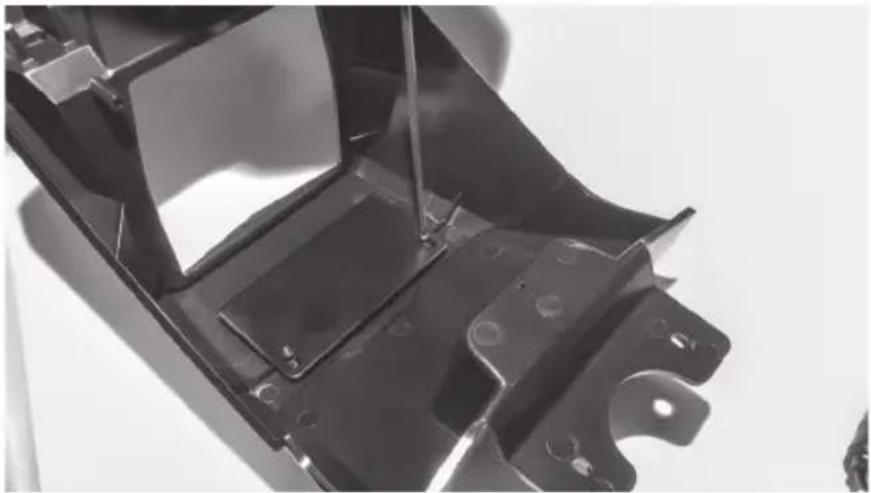
natural_image
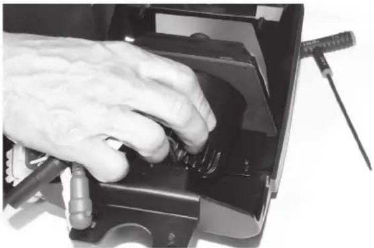
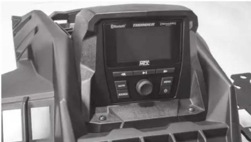
Close-up of a black metal automotive chassis frame with mounting holes and structural ribs (no text or symbols visible)Step 6 - Sliding the plate toward the rear of the kit, install the radio into the kit opening from the rear making sure the top of the radio is between the kit face and compression plate. Once in position, press the radio forward into the opening until it is flush with the front and aligned with the pre-molded screw holes.
natural_image
Close-up of a hand using a screwdriver to press internal components on a device (no visible text or symbols)Step 7 - Using the two (2) longer screws, secure the bottom of the radio to the kit.
natural_image
Close-up of hands working on an electronic device with wires and a bulb (no visible text or symbols)Step 8 - While pressing the pressure plate forward against the radio chassis, tighten the two (2) screws left loose in Step 5.
natural_image
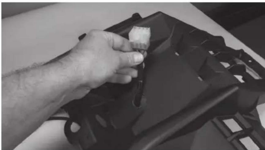
Close-up of a mechanical component with a metal bracket and a black rod inserted (no visible text or symbols)Step 9 - Prepare the pigtail harness supplied with the AWMC3 radio for installation by connecting additional wire to reach power / ground locations, speaker wire if needed and amplifier turn on wire. Note: If the radio installation is part of a full plug and play kit, use the pigtail supplied with the kit and not the radio. Start the installation by passing the pigtail harness down through the 1" hole previously drilled.
natural_image
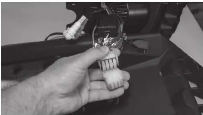
Close-up of a hand holding a small object over a black plastic bag (no visible text or symbols)Step 10 - At this time, any RCA signal wires should be fed up through the hole for connection to the radio unit. Once wires are in place, make the appropriate connections to the radio.
natural_image
Close-up of a hand holding a small electronic component with wires and connectors (no visible text or symbols)Step 11 - With connections made, collect the wire harness under the kit shroud and place the radio kit on top of the dash aligning it with the four (4) holes drilled earlier. Making sure all wires are tucked under the kit, secure it in place with the four (4) screws provided
Step 12 - With the radio secure, make the appropriate electrical connections to complete the install such as power, ground and remote turn on for amplifiers.
Step 13 - Reassemble and go ride.
WARRANTY PERIOD
At MTX Audio we engineer products that will stand up to the test of time. We also realize that from time to time a problem may occur. That's why our products carry a 2-year limited warranty that begins at the time of sale to the end user.
Of course, we're here to help. If you experience an issue with any of our products within the warranty period, please contact our customer service technical line at 1-800-CALL-MTX to help troubleshoot your issue. If, after speaking with our technical experts it is determined that a problem lies with the product, the technician will provide you with a Return Authorization number and all relevant details you'll need to get the product taken care of.
MITEK WARRANTY
MiTek Mobile products (including, but not limited to: MTX, Coustic, Streetwires, Xtant, BassSlammer, and Thunder Marine) purchased in the USA from an AUTHORIZED MITEK DEALER are guaranteed against defects in material and workmanship for the period of time specified. The warranty period begins the day the product is purchased by the end user, and this warranty is limited to the original retail purchaser of product. Products found to be defective during the warranty period will be repaired or replaced with equivalent product by MiTek at no charge. This warranty is void if it is determined that unauthorized parties have attempted repairs or alterations of any nature, and the warranty does not extend to cosmetics or finish. MiTek disclaims any liability for other incurred or consequential damages resulting from product defects. MiTek's total liability will not exceed the purchase price of the product.
NOTES
NOTES

Let's Get Social
mtx.com

natural_image
Four black square icons representing social media platforms: Instagram, Twitter, Facebook, and YouTube (no text or symbols beyond logos)Like, Follow, & Subscribe
© 2021 MiTek Corporation. All rights reserved. MTX is a trademark of MiTek Corporation. All other trademarks are property of their respective owners. Designed and Engineered in the U.S.A.
Due to continual product development, all specifications are subject to change without notice.
MTX Audio, 4545 East Baseline Rd. Phoenix, AZ 85042 U.S.A. 1-800-225-5689
MTX006220 RevA 1/21 • 21A10809 • AW0015864
MX® AUDIO
natural_image
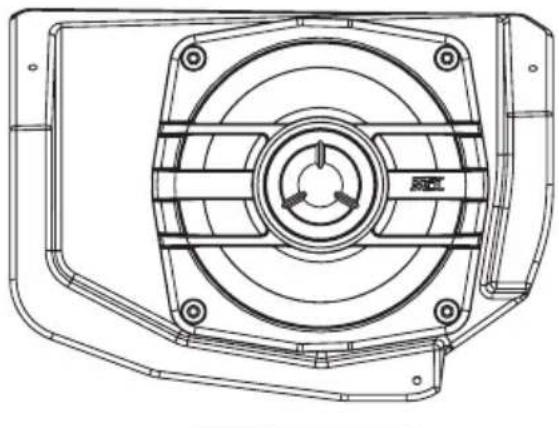
Technical line drawing of a mechanical component with concentric circular features and mounting holes (no text or symbols)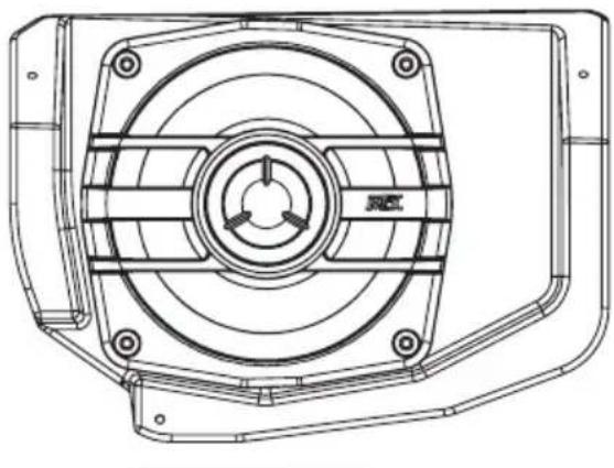
natural_image
Technical line drawing of a mechanical component with concentric circles and mounting holes (no text or symbols)X3-17-FS-U
CAN-AM® MAVERICK X3 FRONT UPPER SPEAKER PODS
OWNER'S MANUAL

THANK YOU
Thank you for making the AWESOME decision to purchase our MTX Audio 4" weatherproof upper dash speakers for your Can-Am® Maverick X3. With a few simple tools from your trusty toolbox you'll have these installed in no time. The rotationally molded enclosures are built as a single piece, designed to take years of abuse without failure and they install quickly with only minor disassembly of the vehicle. So, congratulations on your purchase, thanks for your support and most importantly, enjoy the ultimate audio experience with MTX!
WE'RE HERE TO HELP
We're here to help with any installation or technical support. Visit mtx.com to chat, call 1-800-225-5689 to speak with an MTX Technical Support representative, or visit youtube.com/user/MTXAudioUSA to view product videos.
DON'T FORGET TO REGISTER YOUR PRODUCT
Don't forget to register your new MTX Audio product. Visit mtx.com/productregistration or scan the QR code to the right.
Model #
Serial #
Dealer's Name
Date of Purchase

IMPORTANT NOTICE
Whenever working on the vehicle, it is recommended to disconnect the battery prior to starting work. Failure to do so may lead to a risk of electric shock or equipment damage.
When connecting power and ground wires ensure that the red power wire is fused at the point where it is connected to the vehicle's battery. Failure to do so can result in damage to the vehicle if a short circuit develops between the vehicle connection point and the product.

FEATURES
- Custom Fit for Maverick X3 Dash
- Custom Quick Mount Bracket for Easy Installation
- Rotationally Molded Sealed Enclosure
• Factory Matched Texture
• Polypropylene Woofer and Mylar Dome Tweeter
• Installer Friendly Design - Direct Fit, No Cutting Required
SPECIFICATIONS
• RMS Power Handling: 50-Watts
• Peak Power Handling: 100-Watts
• Sensitivity (2.83V/1m): 89.9dB
• Sensitivity (1W/1m): 85.6dB
• Frequency Response: 75Hz - 20kHz
- Impedance: 4
FIT GUIDE
Turbo / Max Turbo 2018 - 2019
Turbo R / Max Turbo R....2017 - 2019
X-DS Turbo 2017
X-RS Turbo R / Max X-RS Turbo R....2017 - 2019
X-DS Turbo R / Max X-DS Turbo R 2018 - 2019
X-MR Turbo 2019 - 2021
X-MR Turbo R....2019
X-RC Turbo 2019 - 2021
X-MC Turbo R....2019
DS Turbo / Max DS Turbo 2020 - 2021
RS Turbo 2020
DS Turbo R / Max DS Turbo R 2020 - 2021
Max DS Turbo RR 2020
RS Turbo R / Max RS Turbo R....2020 - 2021
X-RC Turbo RR 2020 - 2021
X-RS Turbo RR / Max X-RS Turbo RR....2020 - 2021
X-MR Turbo RR / Max X-MR Turbo RR 2020 - 2021
X-MS Turbo RR 2020
X-DS Turbo RR / Max X-DS Turbo RR 2020 - 2021
IN THE BOX
• X3-17-FS-U Dash Speaker Pods (Left and Right Enclosures)
- Mounting Hardware
(4) T-20 Machine Screws
(2) T-20 Coarse Thread Screws
INSTALLATION
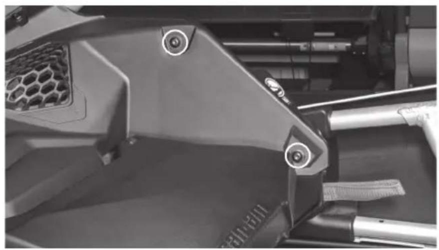
Step 1 - On the driver side, locate and remove seven (7) T-30 Torx screws and two (2) pushpin rivets from the driver's side upper dash panel.
- Two (2) located to the left of the steering wheel.
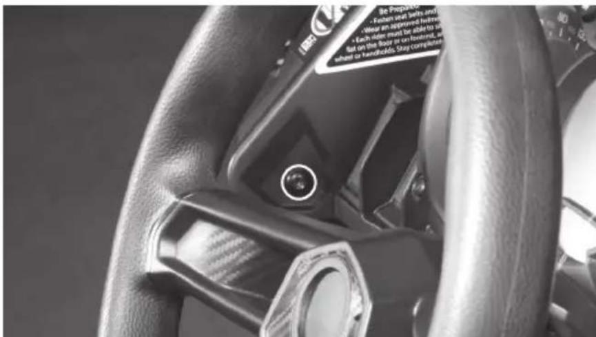
- Three (3) located at the front along the windshield line.
natural_image
Close-up of a car's front bumper with hexagonal grille and three circular buttons (no visible text or symbols)- Two (2) located on either side of the steering wheel.
natural_image
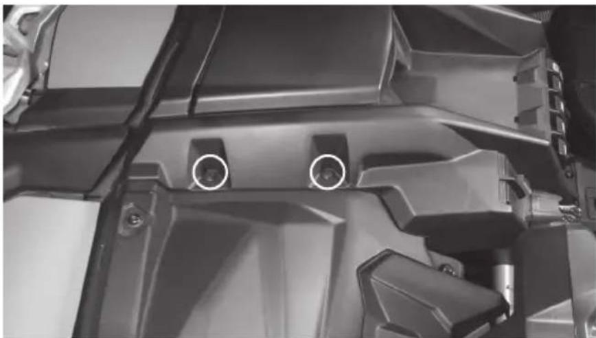
Close-up of a mechanical component with visible mounting holes and a small circular mark on the front (no text or symbols)- Two (2) pushpins located on the right side of the panel at top center tray.
natural_image
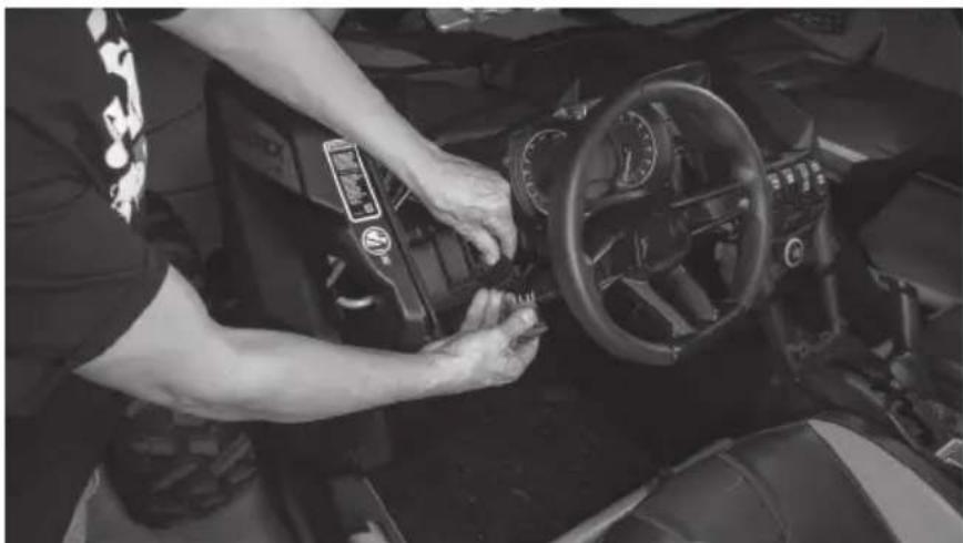
Close-up of a mechanical component with two circular features, no visible text or symbolsStep 2 - Disconnect the light switch harness from the back of the switch. Note: If any additional switches are mounted in this panel, disconnect at this time. If necessary, label harnesses to ensure proper reconnection.
natural_image
Person adjusting a car interior control panel, no visible text or symbols on the dashboard or backgroundStep 3 - Release and push the steering wheel to its lowest position for proper clearance.
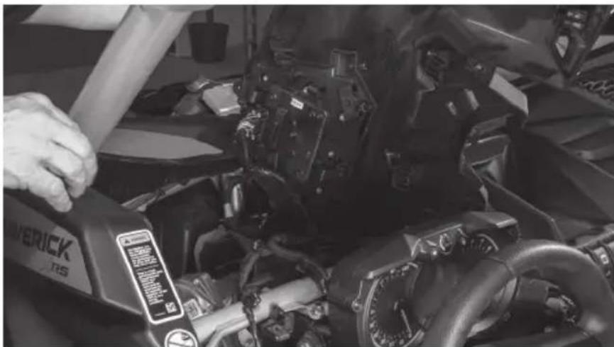
Step 4 - Lift up on the dash panel releasing the harness clips from the bottom side as you do.
natural_image
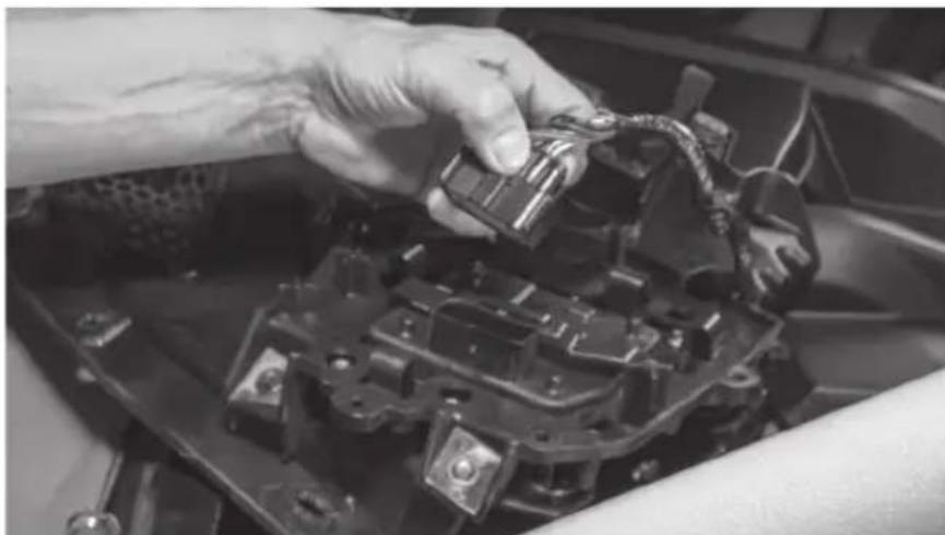
Close-up of a person using a power switch to adjust or install a mechanical component (no visible text or symbols)Step 5 - Once the panel is loose, disconnect the computer harness from the computer module attached to the panel and remove the panel from the vehicle. Note: It is not necessary to remove the computer module from the panel for installation of the speaker pod.
natural_image
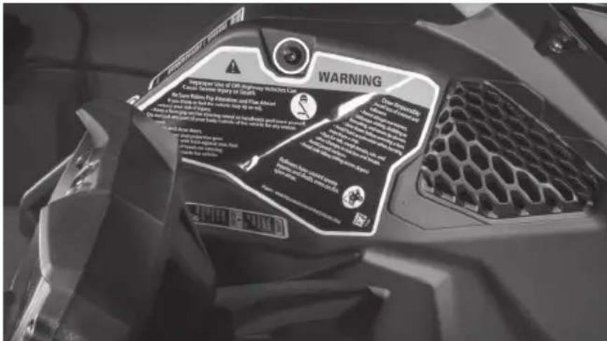
Close-up of hands installing or adjusting a mechanical component with a tool (no visible text or symbols)Step 6 - On the passenger side, locate and remove five (5) T-30 Torx screws, one with 10mm nut, and two (2) pushpin rivets from the passenger's side upper dash panel.
- Two (2) located on the right side upper dash, one has a 10mm nut located behind gas cap cover panel.
natural_image
Close-up of a mechanical assembly with visible gears and brackets (no text or symbols)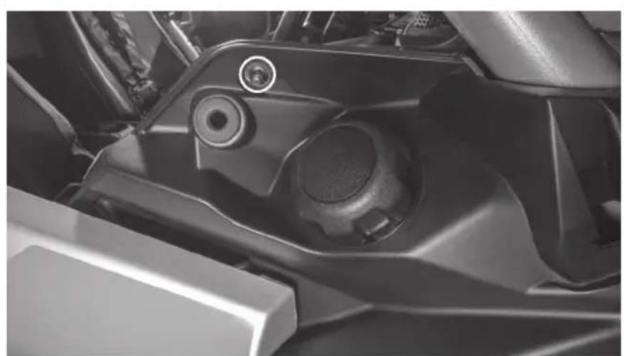
natural_image
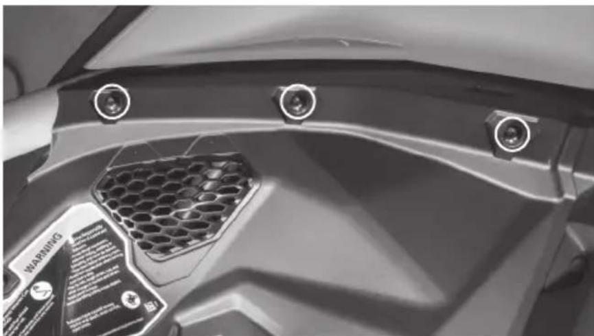
Close-up of a mechanical component with a circular bolt and lever mechanism (no visible text or symbols)- Three (3) located at the front along the windshield line.
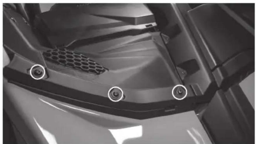
natural_image
Close-up of a mechanical component with hexagonal mesh and three circular features, no visible text or symbols.- Two (2) pushpins located on left side of the panel at top center tray.
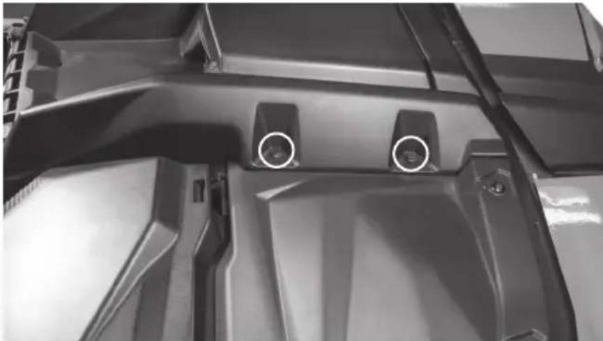
natural_image
Close-up of a mechanical component with two circular features and mounting holes (no visible text or symbols)Step 7 - With hardware removed, lift up on the dash panel releasing the harness clips from the bottom side as you do.
Step 8 - Once the panel is free, remove the panel from the vehicle.
Step 9 - Prep the panels for installation by removing the speaker opening cover panel located on the bottom side of each panel. Note: Your vehicle may not have these installed if panels have been replaced or if audio equipment was previously installed. If missing, move on to the next step.
natural_image
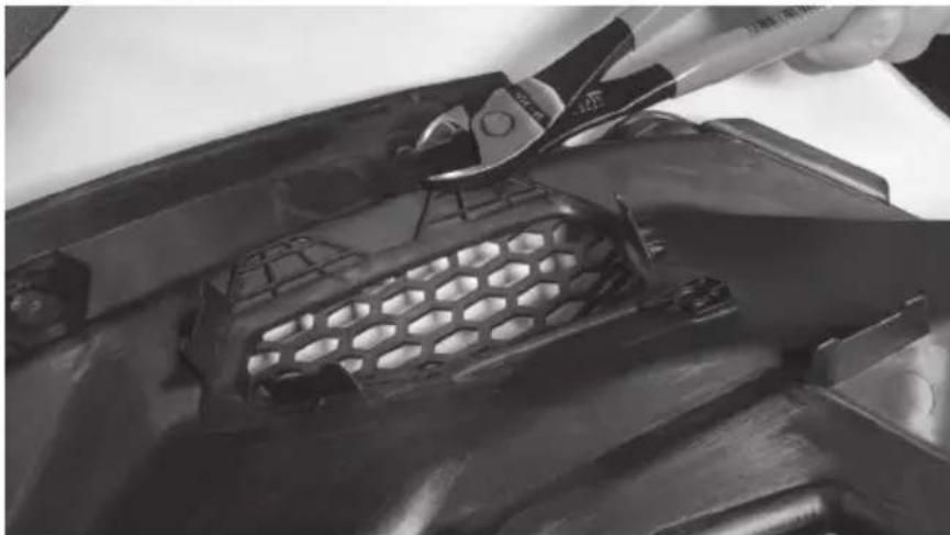
Close-up of a hand using a power tool to clean or store metal components, no visible text or symbolsStep 10 - Using side cutters or a razor knife, remove the four (4) mounting tabs on the bottom side of the panel around the speaker opening to provide proper clearance for the pod installation. Note: These DO NOT need to be perfectly flush with the back of the panel.
natural_image
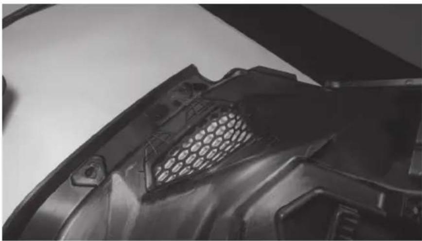
Close-up of a black plastic car hood with hexagonal mesh grille (no text or symbols visible)Step 11 - Turn the panel over and locate the three (3) dimples around the molded speaker grill. Two (2) on top and one (1) on bottom of the grill area.
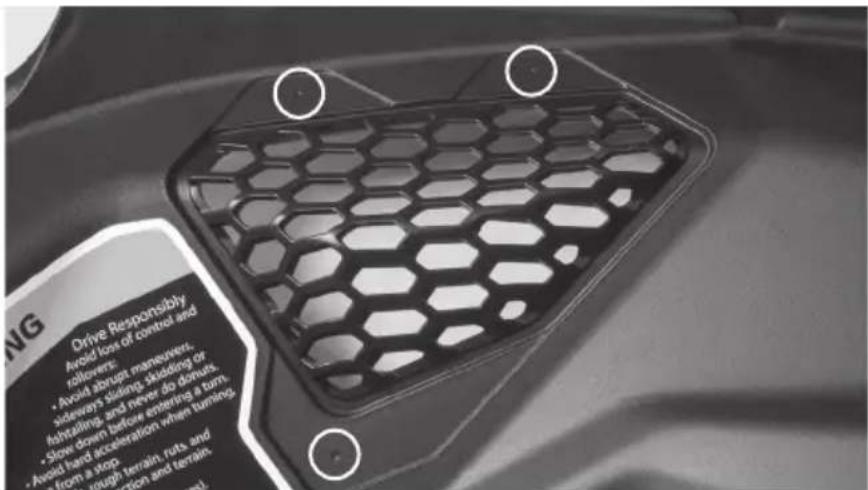
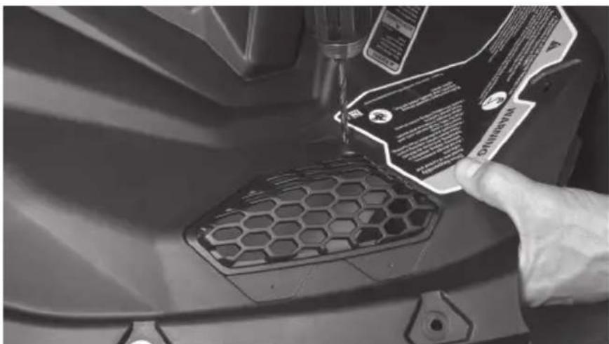
Step 12 - Using a 316 drill bit, drill though the panel at each dimple location.
Step 13 - On the speaker pods, locate the single molded dimple at the bottom of the pod face.
Step 14 - Using a 18 " drill bit, pre-drill the hole approximately 18 " deep to allow the mounting screw to be started by hand.
natural_image
Close-up of a mechanical component with no visible text or symbolsStep 15 - Align the appropriate speaker pod on the back of the panel with the drilled holes and begin securing using two (2) machine screws through the front of the panel and into the threaded holes located on the pod bracket.
natural_image
Close-up of hands working on a mechanical component with tools, no visible text or symbolsStep 16 - Once started, install the coarse thread screw through the single bottom hole into the pod and tighten.
Step 17 - Tighten the machine screws securing the pod to the panel.
Step 18 - Repeat this process on the other panel.
Step 19 - With the panels back at the vehicle, route the pod speaker wire to its connection point. Note: If installing as part of a kit, the upper pod plug will connect to the pigtail located as part of the lower pod harness. If not installing as part of a kit, the plug will need to be removed and additional speaker wire added.
Step 20 - It is recommended to test the system prior to full reassembly. Reinstall the dash panels in reverse order as removed, remembering to reconnect the computer module and any switches disconnected during disassembly.
Step 21 - Reassemble and go ride.
NOTES
NOTES
NOTES
WARRANTY PERIOD
At MTX Audio we engineer products that will stand up to the test of time. We also realize that from time to time a problem may occur. That's why our products carry a 2-year limited warranty that begins at the time of sale to the end user.
Of course, we're here to help. If you experience an issue with any of our products within the warranty period, please contact our customer service technical line at 1-800-CALL-MTX to help troubleshoot your issue. If, after speaking with our technical experts it is determined that a problem lies with the product, the technician will provide you with a Return Authorization number and all relevant details you'll need to get the product taken care of.
MITEK WARRANTY
MiTek Mobile products (including, but not limited to: MTX, Coustic, Streetwires, Xtant, BassSlammer, and Thunder Marine) purchased in the USA from an AUTHORIZED MITEK DEALER are guaranteed against defects in material and workmanship for the period of time specified. The warranty period begins the day the product is purchased by the end user, and this warranty is limited to the original retail purchaser of product. Products found to be defective during the warranty period will be repaired or replaced with equivalent product by MiTek at no charge. This warranty is void if it is determined that unauthorized parties have attempted repairs or alterations of any nature, and the warranty does not extend to cosmetics or finish. MiTek disclaims any liability for other incurred or consequential damages resulting from product defects. MiTek's total liability will not exceed the purchase price of the product.

Let's Get Social
mtx.com

natural_image
Four black square icons representing social media platforms: Instagram, Twitter, Facebook, and YouTube (no text or symbols beyond logos)Like, Follow, & Subscribe
© 2021 MiTek Corporation. All rights reserved. MTX is a trademark of MiTek Corporation. All other trademarks are property of their respective owners. Designed and Engineered in the U.S.A.
Due to continual product development, all specifications are subject to change without notice.
MTX Audio, 4545 East Baseline Rd. Phoenix, AZ 85042 U.S.A. 1-800-225-5689
MTX006224 RevA 1/21 • 21A10811 • AW0015866
MX® AUDIO
natural_image
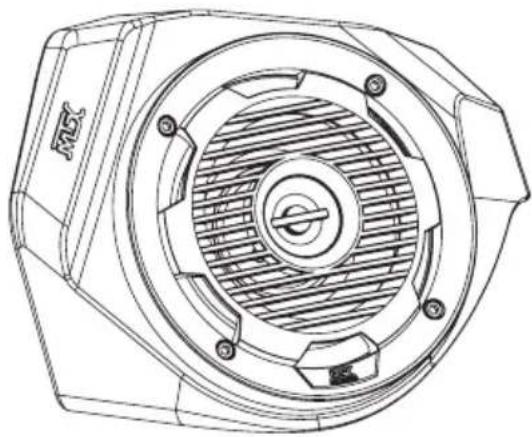
Technical line drawing of a mechanical component with concentric circular features and mounting holes (no text or symbols)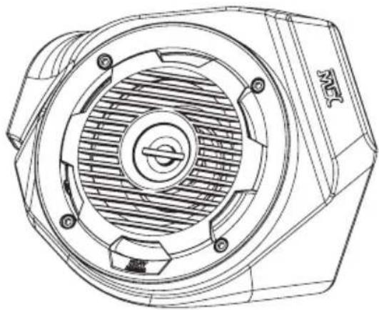
natural_image
Technical line drawing of a mechanical component with concentric circular features and mounting holes (no text or symbols)X3-17-FS-L
CAN-AM® MAVERICK X3 FRONT LOWER SPEAKER PODS
OWNER'S MANUAL

THANK YOU
Thank you for making the AWESOME decision to purchase our MTX Audio 6.5" weatherproof kick panel speakers for your Can-Am® Maverick X3. With a few simple tools from your trusty toolbox you'll have these installed in no time. The rotationally molded enclosures are built as a single piece, designed to take years of abuse without failure and they install quickly with only minor disassembly of the vehicle. And of course, who can forget the integrated RGB lighting in the speakers, because, who doesn't like things that light up, right? So, congratulations on your purchase, thanks for your support and most importantly, enjoy the ultimate audio experience with MTX!
WE'RE HERE TO HELP
We're here to help with any installation or technical support. Visit mtx.com to chat, call 1-800-225-5689 to speak with an MTX Technical Support representative, or visit youtube.com/user/MTXAudioUSA to view product videos.
DON'T FORGET TO REGISTER YOUR PRODUCT
Don't forget to register your new MTX Audio product. Visit mtx.com/productregistration or scan the QR code to the right.
Model # ____
Serial #
Dealer's Name
Date of Purchase

IMPORTANT NOTICE
Whenever working on the vehicle, it is recommended to disconnect the battery prior to starting work. Failure to do so may lead to a risk of electric shock or equipment damage.
When connecting power and ground wires ensure that the red power wire is fused at the point where it is connected to the vehicle's battery. Failure to do so can result in damage to the vehicle if a short circuit develops between the vehicle connection point and the product.

FEATURES
- Integrated RGB LED Lighting
- Custom Fit for Maverick X3 Kick Panel
- Custom Quick Mount Bracket for Easy Installation
- Rotationally Molded Sealed Enclosure
• Factory Matched Texture
• Polypropylene Woofer and Mylar Dome Tweeter
• Installer Friendly Design - Direct Fit, No Cutting Required
SPECIFICATIONS
• RMS Power Handling: 50-Watts
• Peak Power Handling: 100-Watts
• Sensitivity (2.83V/1m): 89.9dB
• Sensitivity (1W/1m): 85.6dB
• Frequency Response: 70Hz - 20kHz
- Impedance: 4
FIT GUIDE
Turbo / Max Turbo....2018 - 2019
Turbo R / Max Turbo R....2017 - 2019
X-DS Turbo 2017
X-RS Turbo R / Max X-RS Turbo R....2017 - 2019
X-DS Turbo R / Max X-DS Turbo R 2018 - 2019
X-MR Turbo 2019 - 2021
X-MR Turbo R....2019
X-RC Turbo 2019 - 2021
X-MC Turbo R....2019
DS Turbo / Max DS Turbo 2020 - 2021
RS Turbo 2020
DS Turbo R / Max DS Turbo R 2020 - 2021
Max DS Turbo RR 2020
RS Turbo R / Max RS Turbo R....2020 - 2021
X-RC Turbo RR 2020 - 2021
X-RS Turbo RR / Max X-RS Turbo RR....2020 - 2021
X-MR Turbo RR / Max X-MR Turbo RR 2020 - 2021
X-MS Turbo RR 2020
X-DS Turbo RR / Max X-DS Turbo RR 2020 - 2021
IN THE BOX
• X3-17-FS-L Kick Panel Speaker Pods (Left and Right Enclosures)
- Door Templates
- 1" Hole Saw
- Mounting Hardware
(4) Mounting Hoop Clamps, (2) per Side
(2) Mounting Plates, (1) per Side
(20) 10mm Bolts, (10) per Side
INSTALLATION
Step 1 - Remove the outer front fender from both the driver and passenger side of the vehicle.
Step 2 - On the driver side, locate and remove eleven (11) screws using a T30 Torx driver and 10mm wrench where needed.
- Six (6) located in the wheel well area, one with a 10mm nut.
natural_image
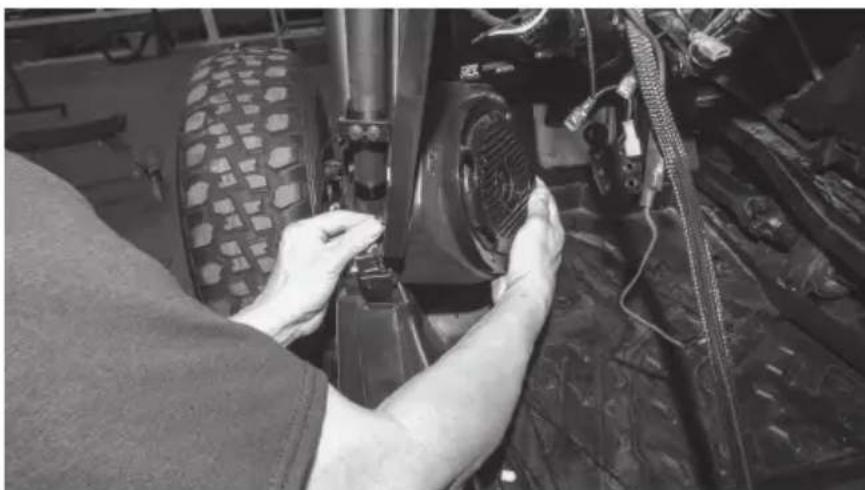
Close-up of a mechanical assembly with springs and a hexagonal component, no visible text or symbols- One (1) located at the top of the fender forward of the roll cage. Note: This is a longer bolt than the rest being removed.
natural_image
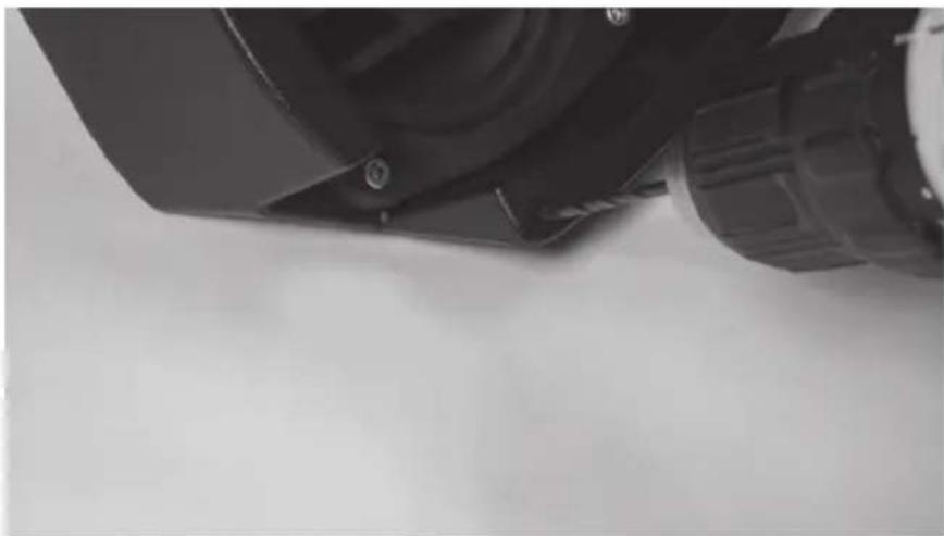
Close-up of a motorcycle's front wheel and side-mounted sensors (no visible text or symbols)• One (1) located in the lower door jamb.
natural_image
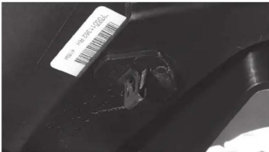
Close-up of a vehicle's lower body and suspension components, showing tire tracks and mechanical assembly (no visible text or symbols)• One (1) located in the front corner by the headlight with a 10mm nut.
natural_image
Close-up of a mechanical component with a circular bolt and threaded shaft (no visible text or symbols)- Two (2) located inside vehicle, top of dash.
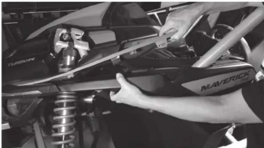
Step 3 - Remove two (2) metal clips and plastic retaining plates from the underside of the fender section attaching it to the driver's side hood trim piece.
Step 4 - Once the clips are removed, lift up on the hood trim and lift the outer fender piece up and back toward the rear of the vehicle to disengage it. Set it aside.
natural_image
Close-up of a person adjusting a Maverick SUV front bumper on a vehicle chassis (no visible text or symbols)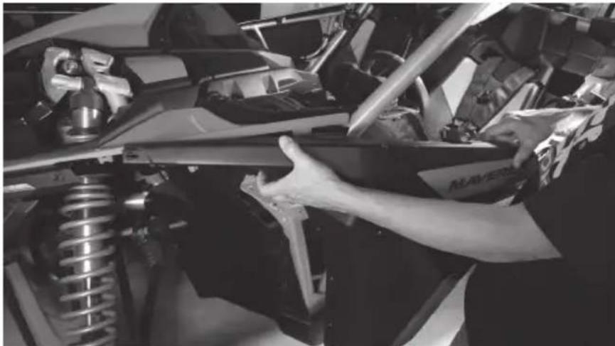
natural_image
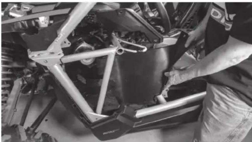
Close-up of a person adjusting a vehicle chassis with visible mechanical components (no text or symbols)Step 5 - The driver's inner footwell panel will also be free now, remove it and set it aside for the installation process.
natural_image
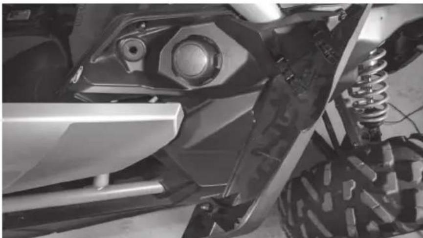
Close-up of a vehicle chassis frame with metal brackets and structural components (no visible text or symbols)Step 6 - On the passenger side, remove the gas cap cover panel and set aside.
natural_image
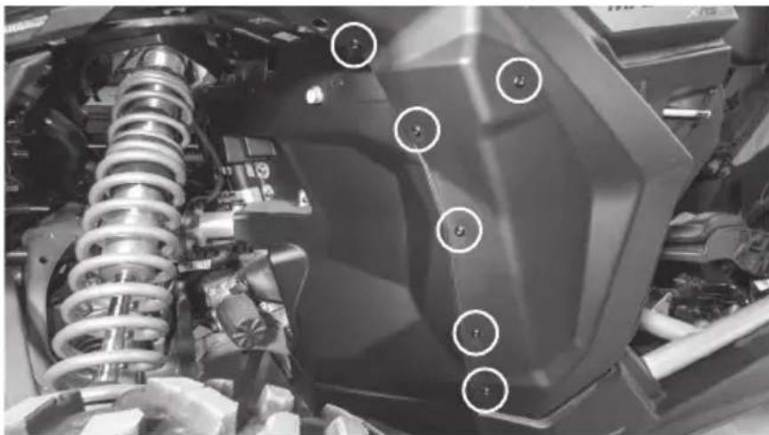
Close-up of a vehicle's front wheel and suspension system (no visible text or symbols)Step 7 - Locate and remove twelve (12) screws using a T30 Torx driver and 10mm wrench where needed.
- Six (6) located in the wheel well area, one with 10mm nut.
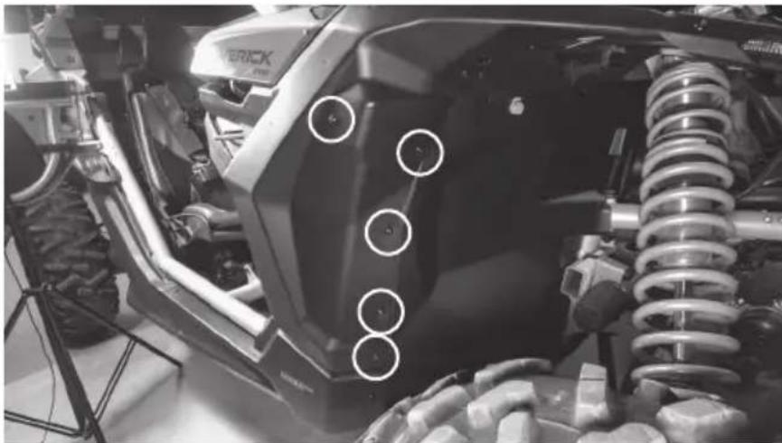
natural_image
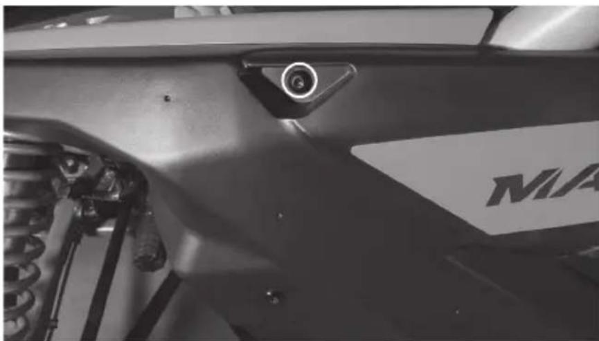
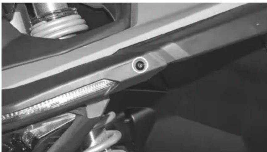
Close-up of a motorcycle's front wheel and suspension system, showing tire tracks and suspension components (no visible text or symbols)- One (1) located at the top of the fender forward of the roll cage behind cover. Note: This is a longer bolt than the rest being removed.
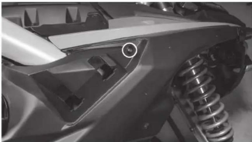
natural_image
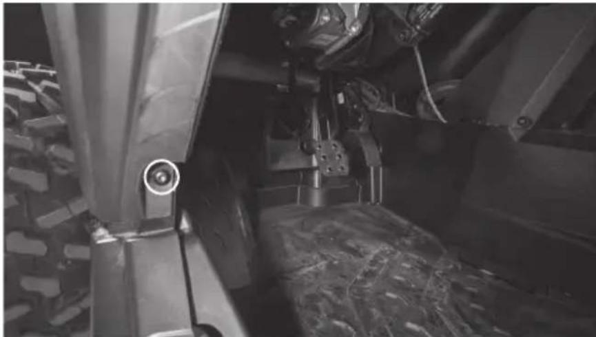
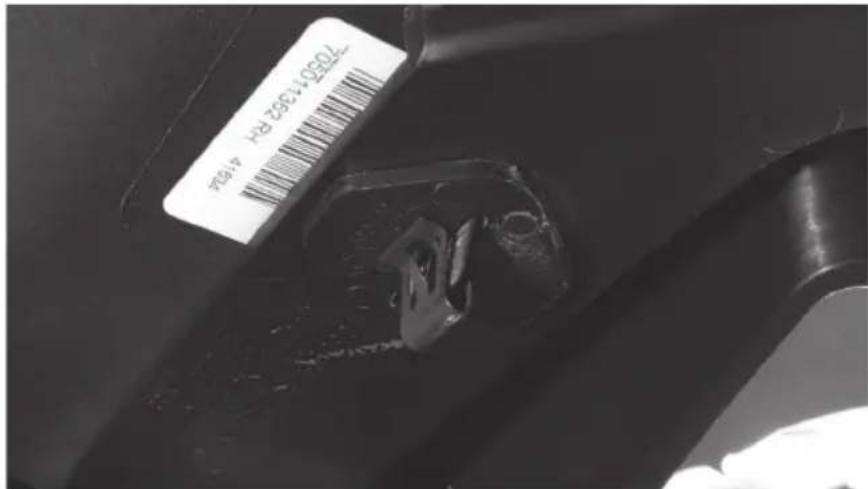
Close-up of a car's front wheel and suspension system, showing mechanical components and a circular detail (no text or symbols visible)• One (1) located in the lower door jamb.
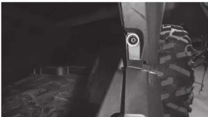
natural_image
Close-up of a heavy-duty off-road vehicle wheel and tire, showing no visible text or symbols• One (1) located in the front corner by the headlight with a 10mm nut.
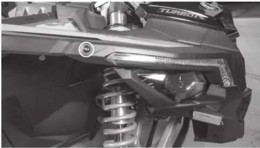
natural_image
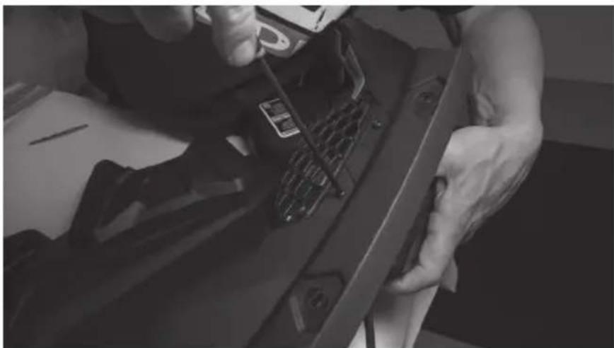
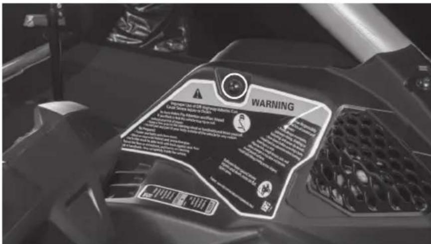
Close-up of a turbocharger assembly with visible spring and valve components (no text or symbols)• One (1) located inside vehicle, top of dash with a 10mm nut on gas cap side.
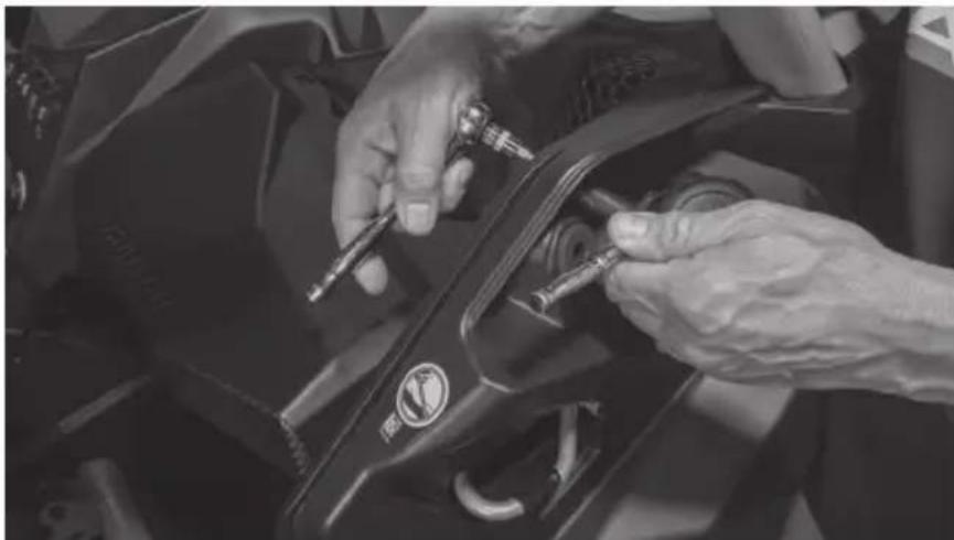
natural_image
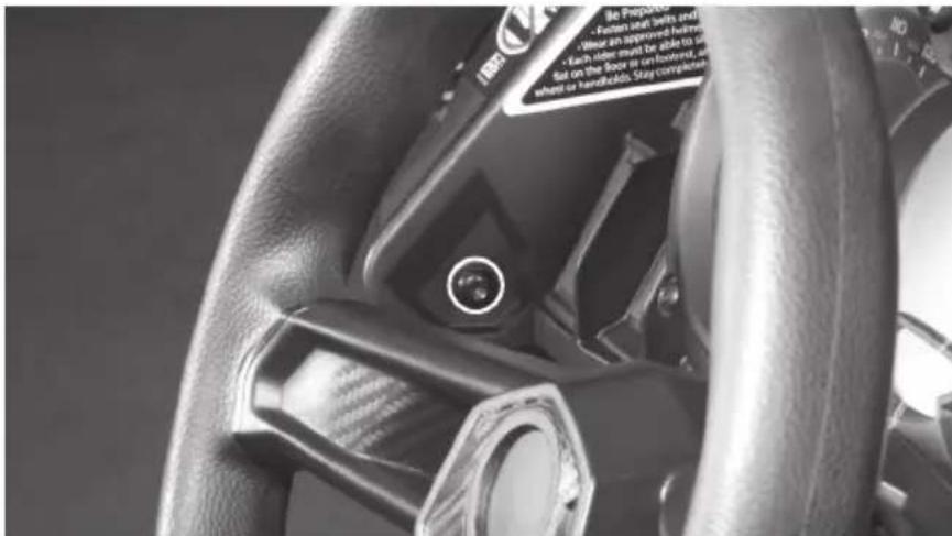
Close-up of hands installing or adjusting a black mechanical component with a tool (no visible text or symbols)• One (1) located inside vehicle, top of dash.
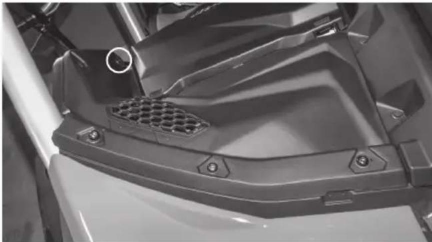
natural_image
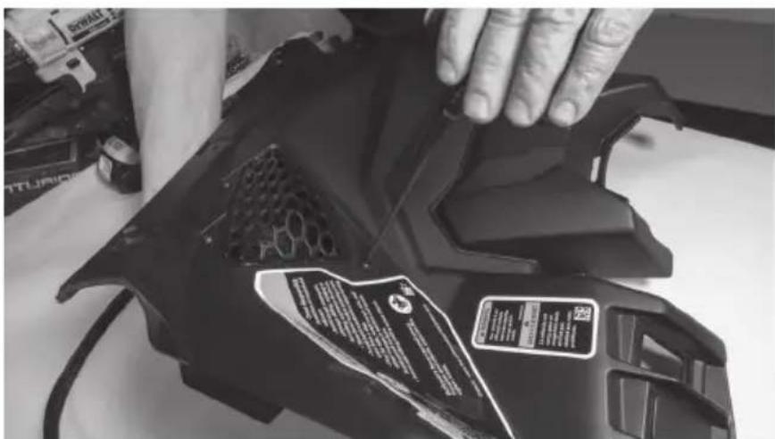
Close-up of a mechanical component with hexagonal grating and mounting holes (no visible text or symbols)- Two (2) from top dash panel.
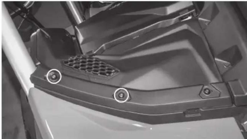
natural_image
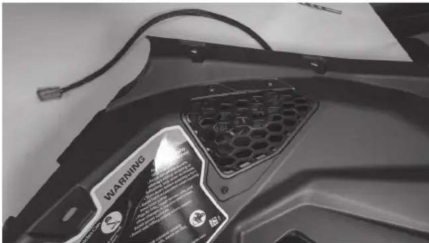
Close-up of a mechanical component with hexagonal grating and mounting holes (no visible text or symbols)Step 8 - Remove two (2) metal clips and plastic retaining plates from the underside of the fender section attaching it to the passenger side hood trim piece.
Step 9 - With these removed, lift the dash panel up from the vehicle exposing the gas filler neck below.
natural_image
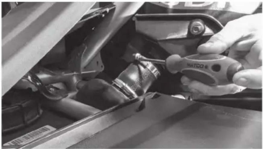
Person adjusting a vehicle tire component in a workshop (no visible text or symbols)Step 10 - Loosen the topmost hose clamp securing the fender assembly to the filler tube and slide the clamp down out of the way.
natural_image
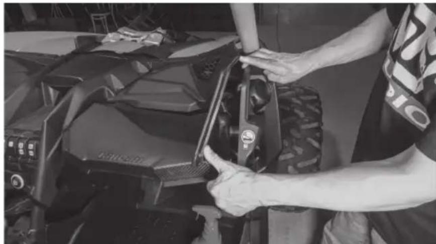
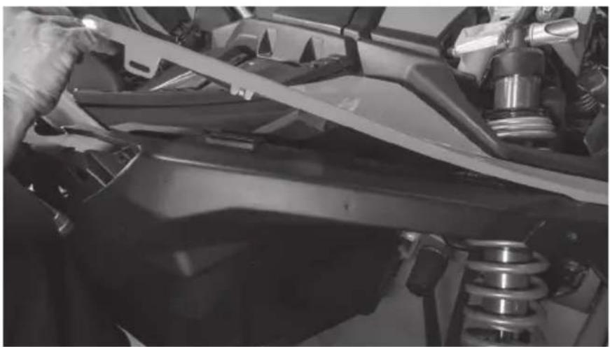
Close-up of hands using a tool to adjust or install a car engine compartment, no visible text or symbolsStep 11 - Lift up on the hood trim piece and pull the fender up and away from the vehicle to remove it. Once removed, set aside. Note: Once removed, cover or stuff a clean rag into the filler tube to prevent gas fumes from escaping.
natural_image
Close-up of a person using a tool to adjust or install a vehicle's roof panel (no visible text or symbols)Step 12 - Starting with the removed driver's interior panel, locate and align the driver side template supplied with the speakers as shown. Note: Templates and mounting plates are marked relative to the side of the vehicle they are for. Ensure you pay attention to and use the appropriate parts for installation for proper fitment.
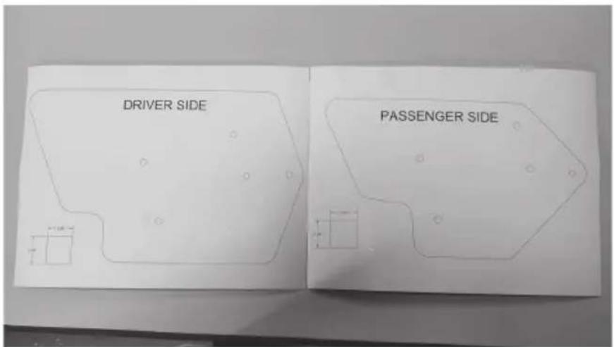
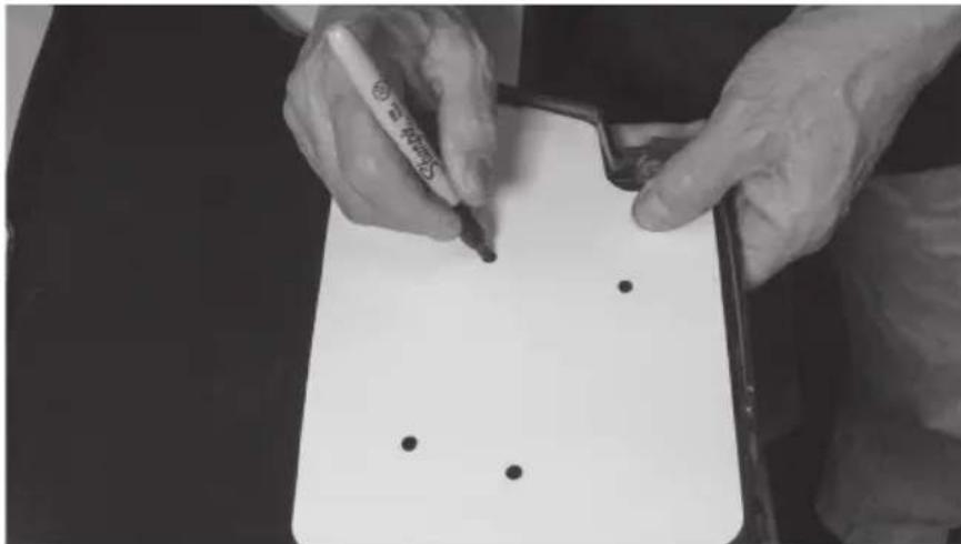
Step 13 - Mark the five (5) holes with a marker or marking device.
natural_image
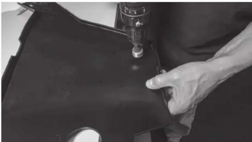
Close-up of hands writing on a notepad with black dots, no visible text or symbolsStep 14 - Using the supplied 1" hole saw, drill at each of the marked locations.
natural_image
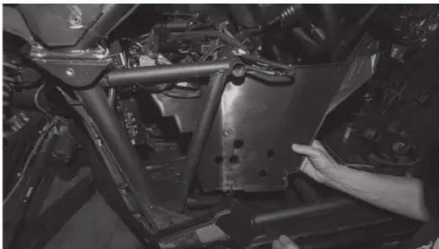
Close-up of a hand operating a sewing machine needle on a dark fabric garment (no visible text or symbols)Step 15 - Once the holes are drilled, temporarily reinstall the interior panel by reinserting the screw removed from the lower door jamb location.
natural_image
Close-up of a hand adjusting a metal frame component in a vehicle chassis (no visible text or symbols)Step 16 - Repeat this process on the passenger side interior panel using the passenger side template.
Step 17 - Starting on the driver's side, begin by installing two hoop clamps over the vertical frame tube with the lower clamp facing the front of the vehicle and the upper facing the rear.
natural_image
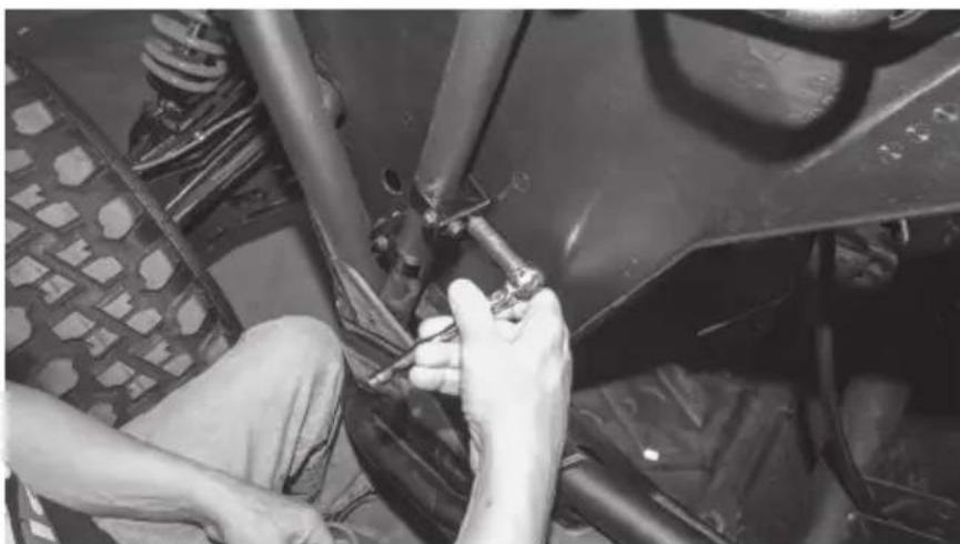
Close-up of a hand using a tool to adjust or install a metal component, no visible text or symbolsStep 18 - Using two (2) longer 10mm bolts supplied, install the two saddle pieces into the hoop clamps leaving them loose enough to move up and down the frame tube.
natural_image
Close-up of hands installing or adjusting a mechanical component on a vehicle (no visible text or symbols)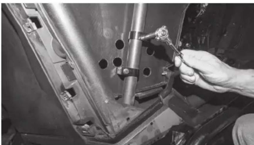
natural_image
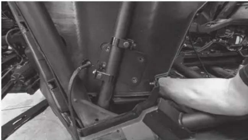
Close-up of a hand using a tool to adjust or install a mechanical component on a vehicle chassis (no visible text or symbols)Step 19 - Slide the correct mounting plate behind the frame tube aligning the clamps with the mounting slots on the plate. The holes of the plate should align with the holes you've already drilled in the inner fender panel. Plates are marked for driver and passenger's side.
natural_image
Close-up of hands installing or adjusting a mechanical component on a vehicle chassis (no visible text or symbols)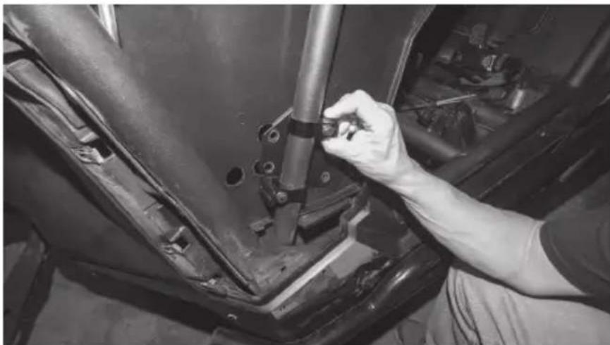
natural_image
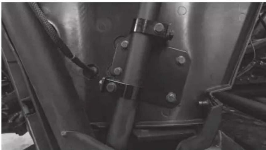
Close-up of a hand adjusting a mechanical component on a vehicle's head (no visible text or symbols)Step 20 - Secure the mounting plate to the clamp assemblies using four (4) 10mm bolts and tighten the clamp bolts.
natural_image
Close-up of hands working on a vehicle's wheel assembly, no visible text or symbolsStep 21 - Pass the driver side pod's harness through the forward most hole.
natural_image
Close-up of a mechanical component with attached connectors and pipes (no visible text or symbols)Step 22 - Holding the pod in place against the inside panel, align the threaded inserts with the holes in the mounting plate.
natural_image
Close-up of a car's engine compartment showing structural components and wiring (no visible text or symbols)Step 23 - Install four (4) 10mm bolts through the plate and secure the pod in place.
natural_image
Person working on a vehicle tire assembly in a workshop (no visible text or symbols)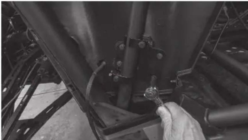
natural_image
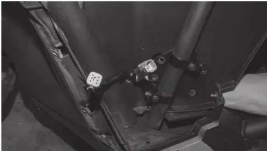
Close-up of a hand adjusting a mechanical component with a wrench, no visible text or symbolsStep 24 - When complete, the plate assembly should appear as shown.
natural_image
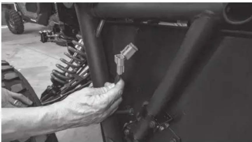
Close-up of a mechanical assembly with bolts and metal components (no visible text or symbols)Step 25 - Route the wire harnesses into the dash and make the appropriate speaker connections
Note: If this install is part of a complete kit, the lower pod harness will connect to the main harness included in that kit. If installing outside a complete kit and hardwire connection need to be made, refer to the diagram for proper connectivity.
natural_image
Close-up of a hand adjusting a mechanical component with a small connector (no visible text or symbols)Step 26 - For the passenger side pod, repeat the steps.
Step 27 - Once the pods are installed and tested, the vehicle can be reassembled in the reverse order as disassembled. Note: The screw in the bottom of the driver's door jamb that was temporarily reinstalled will need to be removed to reinstall the driver's fender.
Step 28 - Reassemble and go ride.
NOTES
WARRANTY PERIOD
At MTX Audio we engineer products that will stand up to the test of time. We also realize that from time to time a problem may occur. That's why our products carry a 2-year limited warranty that begins at the time of sale to the end user.
Of course, we're here to help. If you experience an issue with any of our products within the warranty period, please contact our customer service technical line at 1-800-CALL-MTX to help troubleshoot your issue. If, after speaking with our technical experts it is determined that a problem lies with the product, the technician will provide you with a Return Authorization number and all relevant details you'll need to get the product taken care of.
MITEK WARRANTY
MiTek Mobile products (including, but not limited to: MTX, Coustic, Streetwires, Xtant, BassSlammer, and Thunder Marine) purchased in the USA from an AUTHORIZED MITEK DEALER are guaranteed against defects in material and workmanship for the period of time specified. The warranty period begins the day the product is purchased by the end user, and this warranty is limited to the original retail purchaser of product. Products found to be defective during the warranty period will be repaired or replaced with equivalent product by MiTek at no charge. This warranty is void if it is determined that unauthorized parties have attempted repairs or alterations of any nature, and the warranty does not extend to cosmetics or finish. MiTek disclaims any liability for other incurred or consequential damages resulting from product defects. MiTek's total liability will not exceed the purchase price of the product.

Let's Get Social
mtx.com

natural_image
Four black square icons representing social media platforms: Instagram, Twitter, Facebook, and YouTube (no text or symbols beyond logos)Like, Follow, & Subscribe
© 2021 MiTek Corporation. All rights reserved. MTX is a trademark of MiTek Corporation. All other trademarks are property of their respective owners. Designed and Engineered in the U.S.A.
Due to continual product development, all specifications are subject to change without notice.
MTX Audio, 4545 East Baseline Rd. Phoenix, AZ 85042 U.S.A. 1-800-225-5689
MTX006222 RevA 1/21 • 21A10810 • AW0015865
DRIVER SIDE

X3-17-SW-D / X3-17-SW-P CAN-AM® MAVERICK X3 SUBWOOFER ENCLOSURE OWNER'S MANUAL ADDENDUM
NOTICE
When installing your new X3 subwoofer enclosure, you may notice that the front mounting hole locations may not perfectly align with your seat bracket hole locations. During vehicle manufacturing, some variance can occur in the alignment of the seat brackets. This may require the X3 seat bracket hole on the vehicle to be enlarged before installation to ensure proper fitment and mounting.

natural_image
Technical line drawing of a mechanical assembly with no visible text or symbols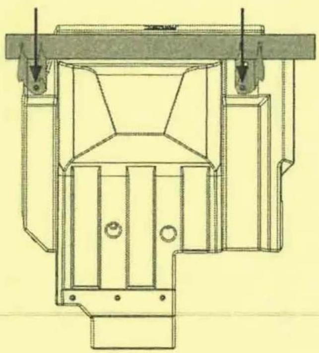
natural_image
Technical line drawing of a mechanical assembly with no visible text or symbols© 2021 MiTek Corporation. All rights reserved. MTX is a trademark of MiTek Corporation. All other trademarks are property of their respective owners. Designed and Engineered in the U.S.A.
Due to continual product development, all specifications are subject to change without notice.
MTX Audio, 4545 East Baseline Rd. Phoenix, AZ 85042 U.S.A. 1-800-225-5689
MTX006458 RevA 4/21 • AW0015962 • 1-12404

natural_image
Technical line drawing of a mechanical component with concentric circular features and mounting brackets (no text or symbols)X3-17-SW-D
CAN-AM® MAVERICK X3 DRIVER SUBWOOFER ENCLOSURE
OWNER'S MANUAL

THANK YOU
Thank you for making the AWESOME decision to purchase our MTX Audio direct-fit subwoofer enclosure designed for the Can-Am® Maverick X3. Our sub enclosure, with its 3512-04S 12" shallow subwoofer, will belt out the bass and deliver ground pounding audio making you the party vehicle in any ride! With a few basic hand tools in your trusty toolbox, you can have this installed in no time. So, what are you waiting for? It's time to get the rumble in your ride and go hit the trails! Oh, and congratulations on your purchase, thanks for your support and most importantly, enjoy the ultimate audio experience with MTX!
WE'RE HERE TO HELP
We're here to help with any installation or technical support. Visit mtx.com to chat, call 1-800-225-5689 to speak with an MTX Technical Support representative, or visit youtube.com/user/MTXAudioUSA to view product videos.
DON'T FORGET TO REGISTER YOUR PRODUCT
Don't forget to register your new MTX Audio product. Visit mtx.com/productregistration or scan the QR code to the right.
Model # ____
Serial #
Dealer's Name
Date of Purchase

IMPORTANT NOTICE
Whenever working on the vehicle, it is recommended to disconnect the battery prior to starting work. Failure to do so may lead to a risk of electric shock or equipment damage.
When connecting power and ground wires ensure that the red power wire is fused at the point where it is connected to the vehicle's battery. Failure to do so can result in damage to the vehicle if a short circuit develops between the vehicle connection point and the product.
FEATURES
- Includes an MTX 3512-04S 12" Shallow Subwoofer
- Mounts Under Driver Seat
• Factory Matched Texture
• Installer Friendly Design - Direct Fit, No Cutting or Drilling Required
SPECIFICATIONS
• 12" Loaded Subwoofer Enclosure
• RMS Power Handling: 300-Watts
• Peak Power Handling: 600-Watts
• Sensitivity (2.83V/1m): 88.5dB
• Sensitivity (1W/1m): 84.4dB
• Frequency Response: 23Hz - 130Hz
- Impedance: 4
FIT GUIDE
Turbo / Max Turbo....2018 - 2019
Turbo R / Max Turbo R 2017 - 2019
X-DS Turbo 2017
X-RS Turbo R / Max X-RS Turbo R....2017 - 2019
X-DS Turbo R / Max X-DS Turbo R 2018 - 2019
X-MR Turbo 2019 - 2021
X-MR Turbo R....2019
X-RC Turbo 2019 - 2021
X-MC Turbo R....2019
DS Turbo / Max DS Turbo 2020 - 2021
RS Turbo 2020
DS Turbo R / Max DS Turbo R 2020 - 2021
Max DS Turbo RR 2020
RS Turbo R / Max RS Turbo R....2020 - 2021
X-RC Turbo RR 2020 - 2021
X-RS Turbo RR / Max X-RS Turbo RR....2020 - 2021
X-MR Turbo RR / Max X-MR Turbo RR 2020 - 2021
X-MS Turbo RR....2020
X-DS Turbo RR / Max X-DS Turbo RR 2020 - 2021
FIT GUIDE NOTES
Only the X3-17-SW-D driver side enclosure includes the signal harness from the amp.
IN THE BOX
• X3-17-SW-D Loaded Subwoofer Enclosure
- Adhesive Foam Tape
- Mounting Hardware
(1) Mounting Bracket
(5) T40 Torx Bolts
INSTALLATION
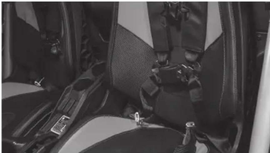
Step 1 - Release the lower seat belt strap from the harness by feeding it back through the tension assembly. This will allow you to feed the shoulder straps through the hole at the top of the seat.
natural_image
Interior view of a car showing seatbelt and passenger seatbelt (no visible text or symbols)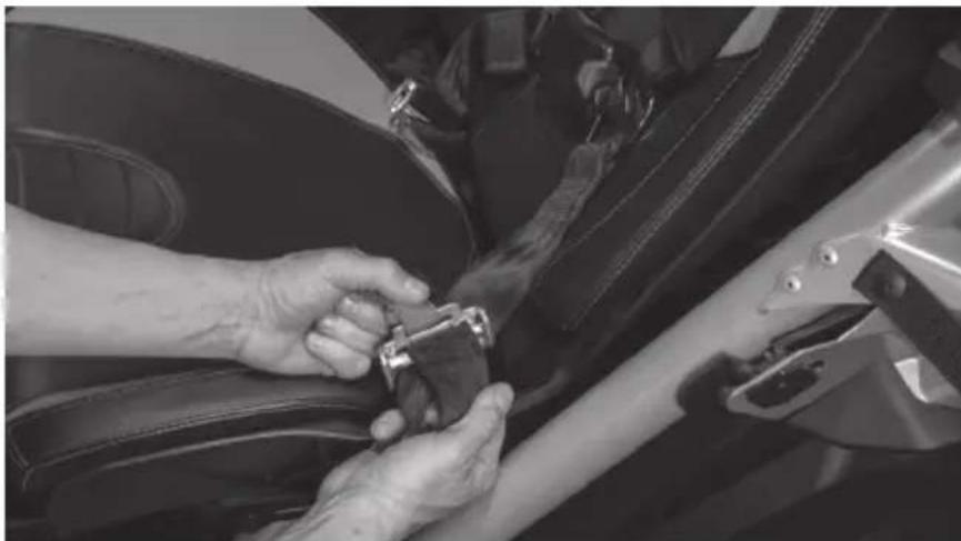
natural_image
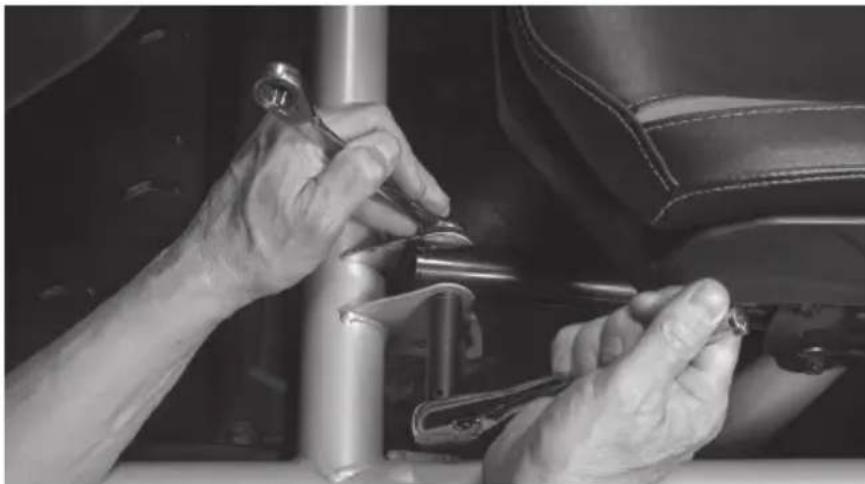
Close-up of hands adjusting a car seatbelt on a vehicle (no visible text or symbols)Step 2 - Remove two (2) 13mm bolts and nuts at the front of the seat frame.
natural_image
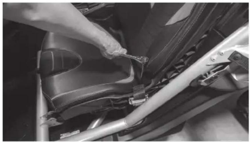
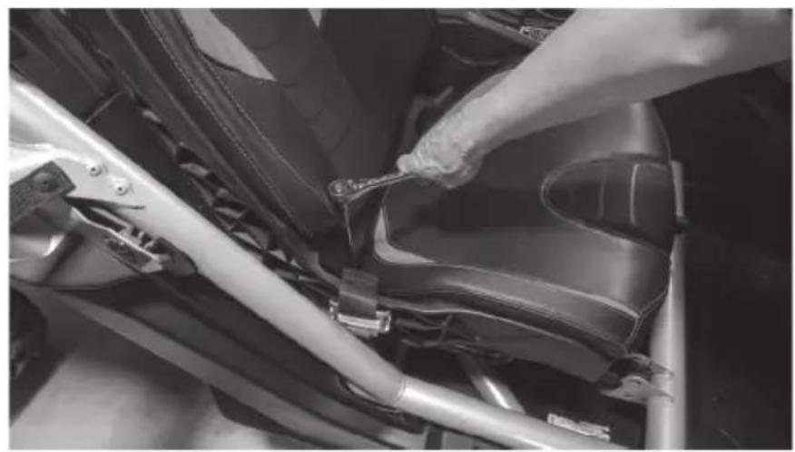
Close-up of hands adjusting a mechanical component in a car seat (no visible text or symbols)Step 3 - Access the rear 18mm nuts using a socket with extension either by aligning the holes in the seat base over the nuts or by sliding the seat fully forward and reaching behind.
natural_image
Close-up of a hand using a wrench to adjust or install a car seatbelt component (no visible text or symbols)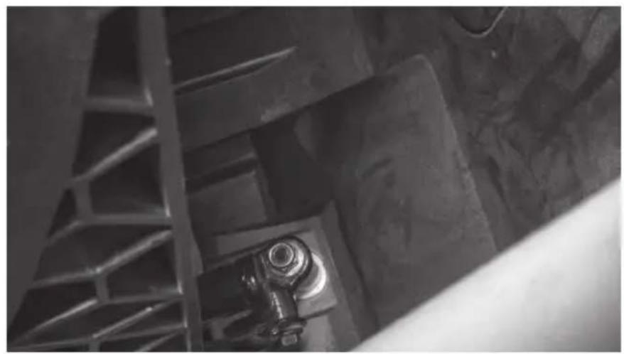
natural_image
Close-up of industrial metal structure with a bolt and ladder (no visible text or symbols)Step 4 - With the seat free, disconnect the seat belt sensor and speed sensor cables from the seat assembly.
Step 5 - Once disconnected, lift the seat out of the vehicle and set aside.
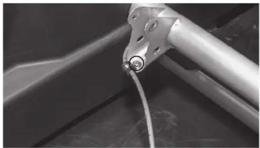
Step 6 - Remove the 10mm M6 bolt holding the brake line clamp in place on the seat frame.
natural_image
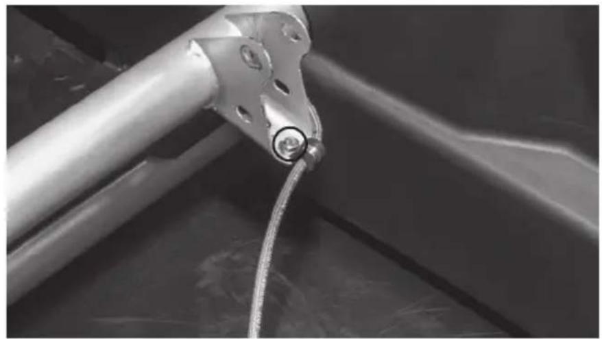
Close-up of a metallic mechanical component with a coiled cable or wire, no visible text or symbols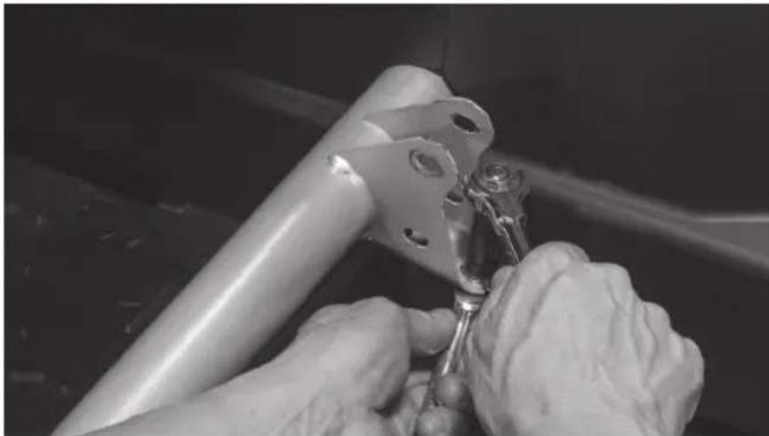
natural_image
Close-up of hands using a tool to adjust or install a metal bracket component (no visible text or symbols)Step 7 - Remove the cable clamp from the brake line.
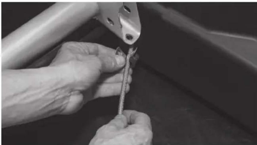
natural_image
Close-up of hands using a tool to adjust or install a metal component (no visible text or symbols)Step 8 - Wrap the brake line with the strip of adhesive backed foam tape included in the box. Note: This step is to prevent the brake line from rattling against the enclosure under high bass output and any chaffing due to movement of the brake line while the vehicle is in motion.
natural_image
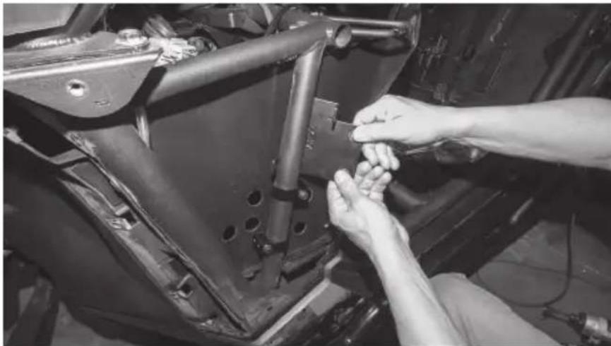
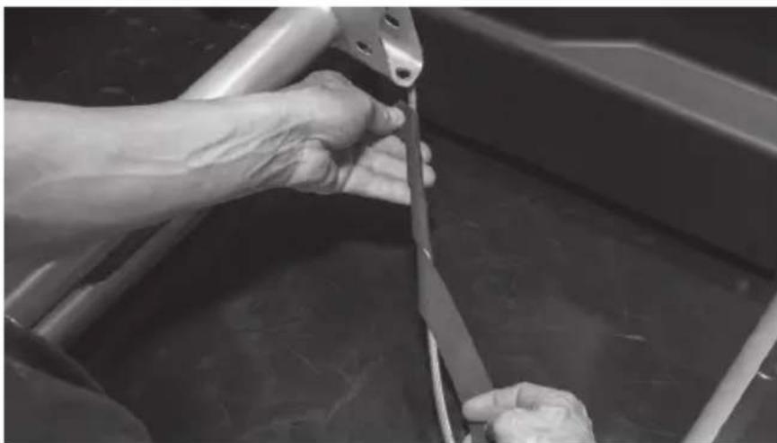
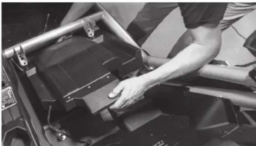
Close-up of hands using a tool to cut or wire on a metal frame (no visible text or symbols)Step 9 - Tilt the front of the enclosure down and slide it under the forward crossbar as you set it in place onto the floor of the vehicle tucking the brake line into the pre-molded slot in the bottom of the enclosure.
natural_image
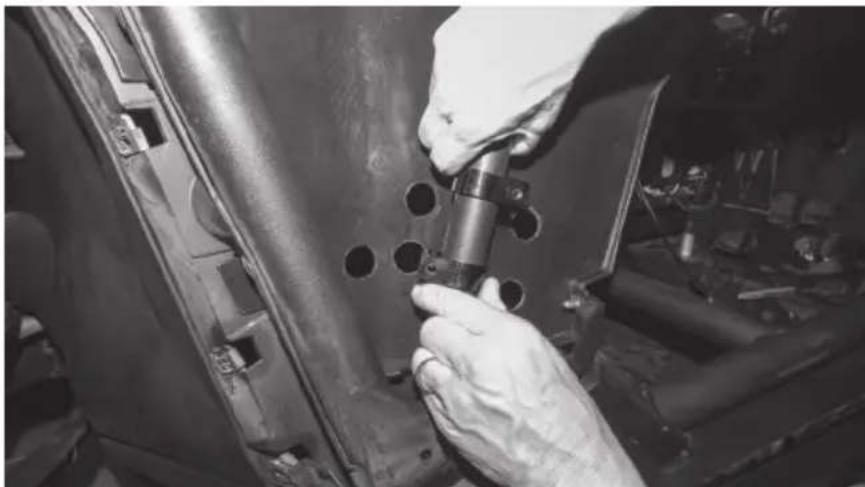
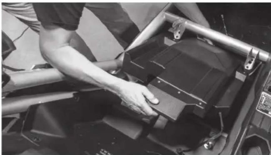
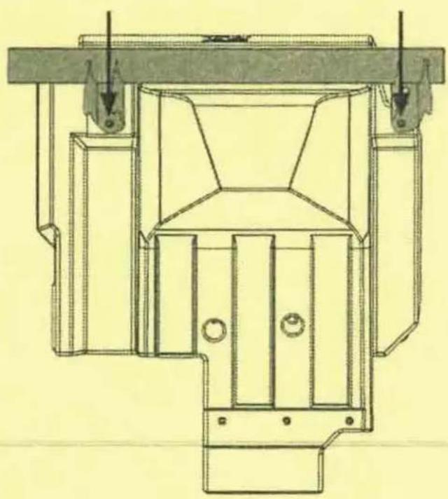
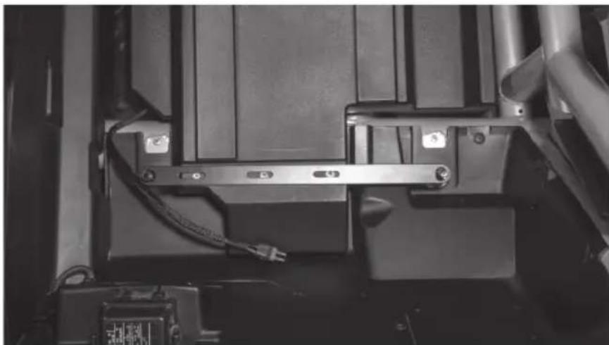
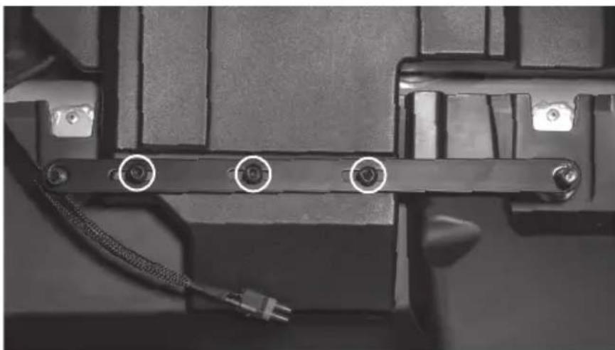
Person adjusting a black metal frame component on a vehicle chassis (no visible text or symbols)Step 10 - Taking the long bar bracket included, align the slotted holes with the threaded insets on the top rear of the enclosure. The two large holes at either end should slide over the threaded seat mounting posts.
natural_image
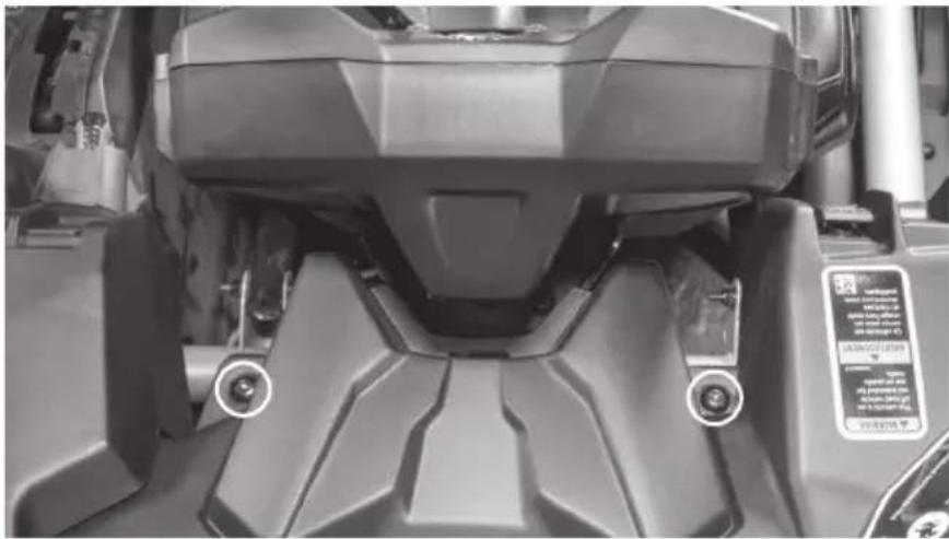
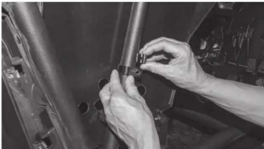
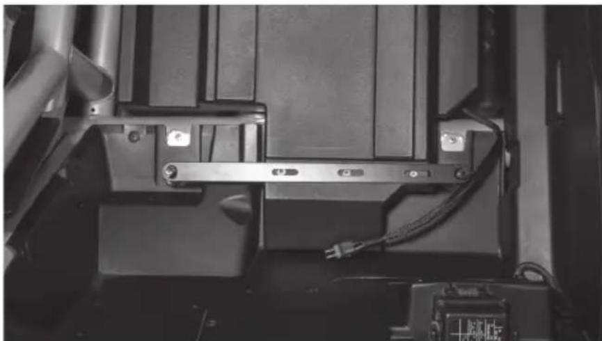
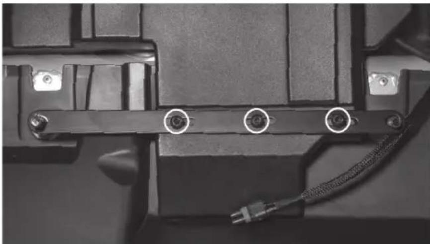
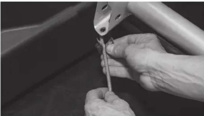
Close-up of a mechanical assembly with metal brackets and wiring (no visible text or symbols)Step 11 - Loosely install three (3) T-40 Torx screws into the bracket.
natural_image
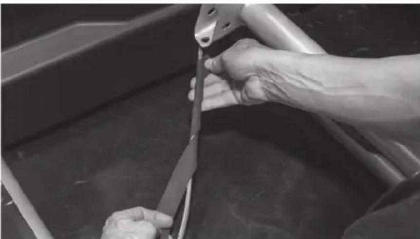
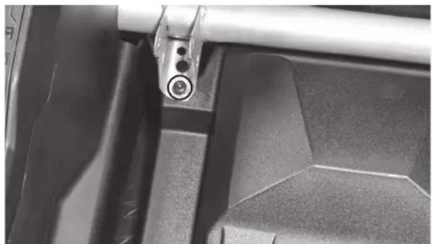
Close-up of a mechanical component with three circular annotations pointing to pins (no text or symbols visible)Step 12 - Align the threaded inserts at the front corners of the enclosure with the holes in the bottom of the seat brackets and insert two (2) T-40 Torx screws.
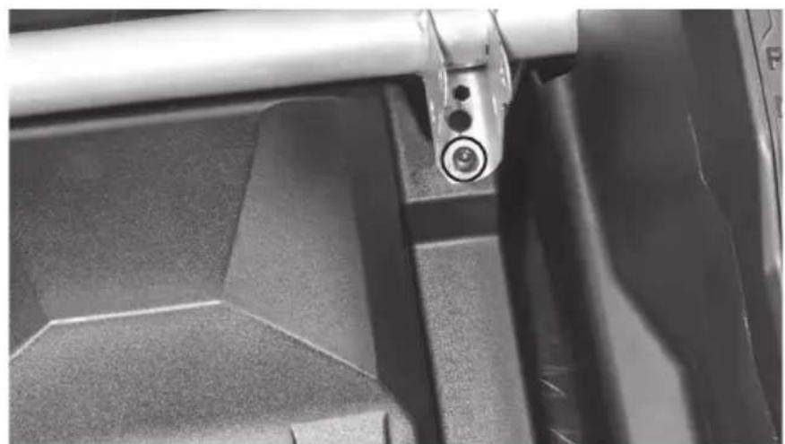
natural_image
Close-up of a mechanical component with a metallic lever and circular end detail (no visible text or symbols)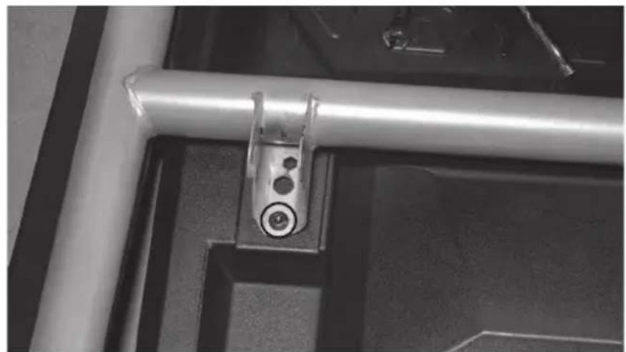
natural_image
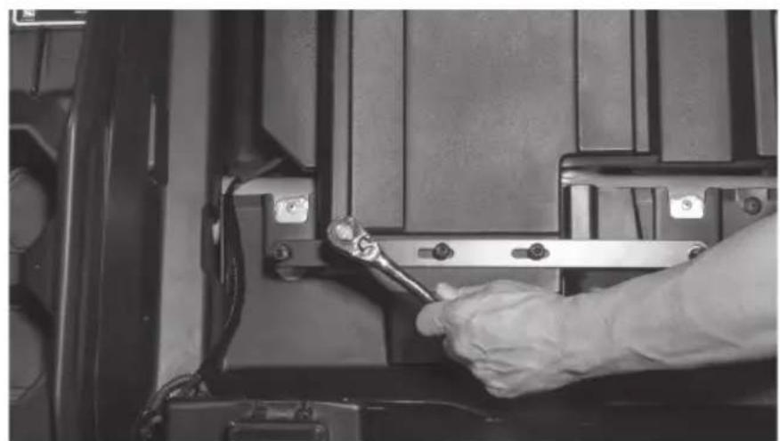
Close-up of a metallic mechanical bracket with a circular screw and mounting holes, mounted on a dark surface (no text or symbols visible)Step 13 - Once all fasteners are in place, tighten to secure the enclosure.
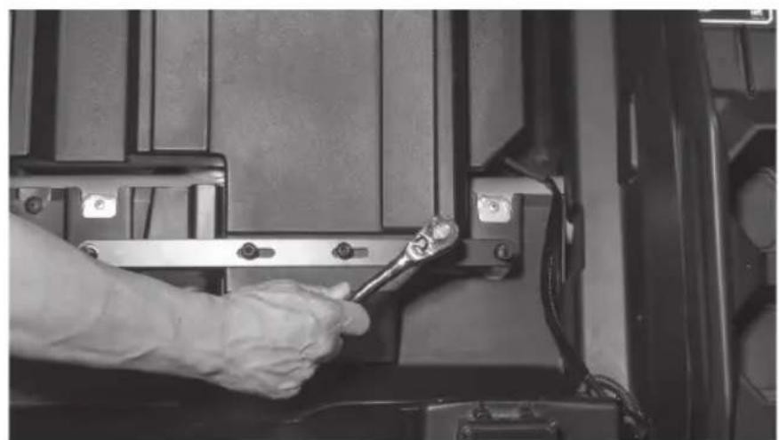
natural_image
Close-up of a hand using a wrench to adjust or install a mechanical component (no visible text or symbols)Step 14 - Route the subwoofer cable to the desired connection point. Note: If installing as part of a kit, the subwoofer plug will connect to the main harness supplied. If not installing as part of a kit, the plug will need to be removed and additional speaker wire added.
Step 15 - With your wire routed and system tested, reinstall the seat in the reverse order as removed. Note: In the event of floor pan rattle, included in the subwoofer kit are a self-tapping drill bit and bolts to allow you to bolt the floor pan directly to the frame of the vehicle. Please refer to the installation videos for more information on their use at www.youtube.com/user/MTXAudioUSA
Step 16 - Reassemble and go ride.
NOTES
WARRANTY PERIOD
At MTX Audio we engineer products that will stand up to the test of time. We also realize that from time to time a problem may occur. That's why our products carry a 2-year limited warranty that begins at the time of sale to the end user.
Of course, we're here to help. If you experience an issue with any of our products within the warranty period, please contact our customer service technical line at 1-800-CALL-MTX to help troubleshoot your issue. If, after speaking with our technical experts it is determined that a problem lies with the product, the technician will provide you with a Return Authorization number and all relevant details you'll need to get the product taken care of.
MITEK WARRANTY
MiTek Mobile products (including, but not limited to: MTX, Coustic, Streetwires, Xtant, BassSlammer, and Thunder Marine) purchased in the USA from an AUTHORIZED MITEK DEALER are guaranteed against defects in material and workmanship for the period of time specified. The warranty period begins the day the product is purchased by the end user, and this warranty is limited to the original retail purchaser of product. Products found to be defective during the warranty period will be repaired or replaced with equivalent product by MiTek at no charge. This warranty is void if it is determined that unauthorized parties have attempted repairs or alterations of any nature, and the warranty does not extend to cosmetics or finish. MiTek disclaims any liability for other incurred or consequential damages resulting from product defects. MiTek's total liability will not exceed the purchase price of the product.

Let's Get Social
mtx.com

natural_image
Four black square icons representing social media platforms: Instagram, Twitter, Facebook, and YouTube (no text or symbols beyond logos)Like, Follow, & Subscribe
© 2021 MiTek Corporation. All rights reserved. MTX is a trademark of MiTek Corporation. All other trademarks are property of their respective owners. Designed and Engineered in the U.S.A.
Due to continual product development, all specifications are subject to change without notice.
MTX Audio, 4545 East Baseline Rd. Phoenix, AZ 85042 U.S.A. 1-800-225-5689
MTX006226 RevA 1/21 • 21A10812 • AW0015867

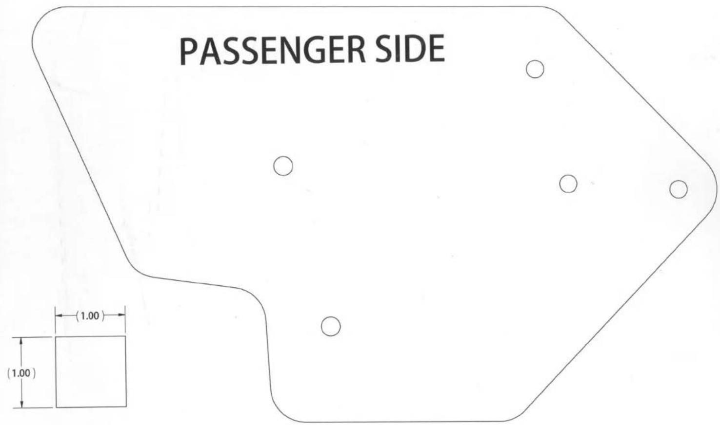
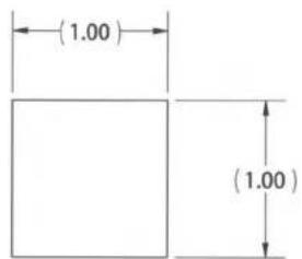
X3-17-SW-D / X3-17-SW-P CAN-AM® MAVERICK X3 SUBWOOFER ENCLOSURE OWNER'S MANUAL ADDENDUM
NOTICE
When installing your new X3 subwoofer enclosure, you may notice that the front mounting hole locations may not perfectly align with your seat bracket hole locations. During vehicle manufacturing, some variance can occur in the alignment of the seat brackets. This may require the X3 seat bracket hole on the vehicle to be enlarged before installation to ensure proper fitment and mounting.
natural_image
Technical line drawing of a mechanical assembly with no visible text or symbols
natural_image
Technical line drawing of a mechanical device with mounting brackets and structural supports (no text or symbols)© 2021 MiTek Corporation. All rights reserved. MTX is a trademark of MiTek Corporation. All other trademarks are property of their respective owners. Designed and Engineered in the U.S.A.
Due to continual product development, all specifications are subject to change without notice.
MTX Audio, 4545 East Baseline Rd. Phoenix, AZ 85042 U.S.A. 1-800-225-5689
MTX006458 RevA 4/21 • AW0015962 • 1-12404
MTX®
AUDIO
natural_image
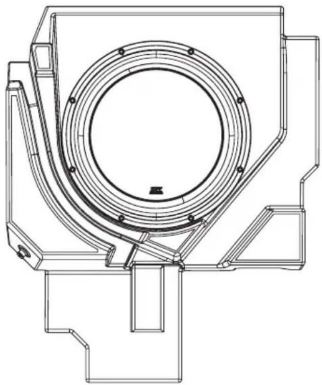
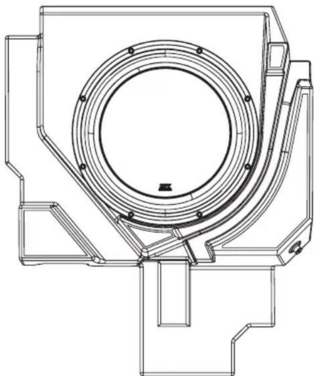
Technical line drawing of a mechanical component with concentric rings and mounting brackets (no text or symbols)X3-17-SW-P
CAN-AM® MAVERICK X3 PASSENGER SUBWOOFER ENCLOSURE
OWNER'S MANUAL

THANK YOU
Thank you for making the AWESOME decision to purchase our MTX Audio direct-fit subwoofer enclosure designed for the Can-Am® Maverick X3. Our sub enclosure, with its 3512-04S 12" shallow subwoofer, will belt out the bass and deliver ground pounding audio making you the party vehicle in any ride! With a few basic hand tools in your trusty toolbox, you can have this installed in no time. So, what are you waiting for? It's time to get the rumble in your ride and go hit the trails! Oh, and congratulations on your purchase, thanks for your support and most importantly, enjoy the ultimate audio experience with MTX!
WE'RE HERE TO HELP
We're here to help with any installation or technical support. Visit mtx.com to chat, call 1-800-225-5689 to speak with an MTX Technical Support representative, or visit youtube.com/user/MTXAudioUSA to view product videos.
DON'T FORGET TO REGISTER YOUR PRODUCT
Don't forget to register your new MTX Audio product. Visit mtx.com/productregistration or scan the QR code to the right.
Model # ____
Serial #
Dealer's Name
Date of Purchase

IMPORTANT NOTICE
Whenever working on the vehicle, it is recommended to disconnect the battery prior to starting work. Failure to do so may lead to a risk of electric shock or equipment damage.
When connecting power and ground wires ensure that the red power wire is fused at the point where it is connected to the vehicle's battery. Failure to do so can result in damage to the vehicle if a short circuit develops between the vehicle connection point and the product.
FEATURES
- Includes an MTX 3512-04S 12" Shallow Subwoofer
- Mounts Under Passenger Seat
• Factory Matched Texture
• Installer Friendly Design - Direct Fit, No Cutting or Drilling Required
SPECIFICATIONS
• 12" Loaded Subwoofer Enclosure
• RMS Power Handling: 300-Watts
• Peak Power Handling: 600-Watts
• Sensitivity (2.83V/1m): 88.5dB
• Sensitivity (1W/1m): 84.4dB
• Frequency Response: 23Hz - 130Hz
- Impedance: 4
FIT GUIDE
Turbo / Max Turbo....2018 - 2019
Turbo R / Max Turbo R 2017 - 2019
X-DS Turbo 2017
X-RS Turbo R / Max X-RS Turbo R....2017 - 2019
X-DS Turbo R / Max X-DS Turbo R 2018 - 2019
X-MR Turbo 2019 - 2021
X-MR Turbo R....2019
X-RC Turbo 2019 - 2021
X-MC Turbo R....2019
DS Turbo / Max DS Turbo 2020 - 2021
RS Turbo 2020
DS Turbo R / Max DS Turbo R 2020 - 2021
Max DS Turbo RR 2020
RS Turbo R / Max RS Turbo R....2020 - 2021
X-RC Turbo RR 2020 - 2021
X-RS Turbo RR / Max X-RS Turbo RR....2020 - 2021
X-MR Turbo RR / Max X-MR Turbo RR 2020 - 2021
X-MS Turbo RR....2020
X-DS Turbo RR / Max X-DS Turbo RR 2020 - 2021
FIT GUIDE NOTES
Only the X3-17-SW-D driver side enclosure includes the signal harness from the amp.
IN THE BOX
• X3-17-SW-P Loaded Subwoofer Enclosure
- Adhesive Foam Tape
- Mounting Hardware
(1) Mounting Bracket
(5) T40 Torx Bolts
INSTALLATION
Step 1 - Release the lower seat belt strap from the harness by feeding it back through the tension assembly. This will allow you to feed the shoulder straps through the holes at the top of the seat.
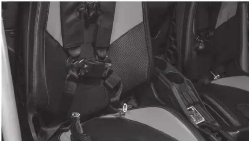
natural_image
Interior view of a car showing seatbelt and driver seat (no visible text or symbols)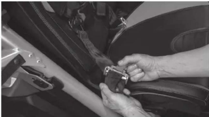
natural_image
Close-up of hands adjusting a car seatbelt on a car's side panel (no visible text or symbols)Step 2 - Remove two (2) 13mm bolts and nuts at the front of the seat frame.
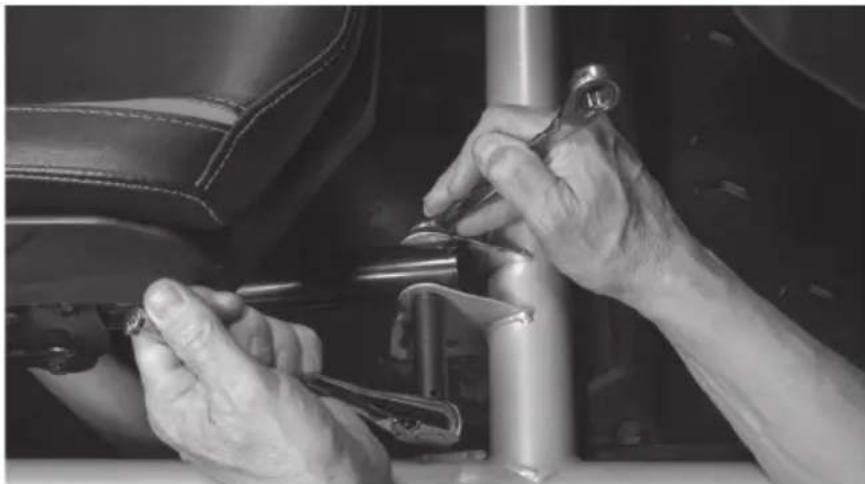
natural_image
Close-up of hands using a wrench to adjust or install a mechanical component on a vehicle (no visible text or symbols)Step 3 - Access the rear 18mm nuts using a socket with extension either by aligning the holes in the seat base over the nuts or by sliding the seat fully forward and reaching behind.
natural_image
Close-up of a person adjusting a car seatbelt mechanism (no visible text or symbols)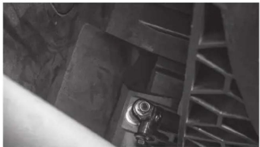
natural_image
Close-up of industrial metal structure with a bolt and pipe fitting (no visible text or symbols)Step 4 - With the seat free, lift the seat out of the vehicle and set aside.
Step 5 - Remove the 10mm M6 bolt holding the brake line clamp in place on the seat frame.
natural_image
Close-up of a metallic mechanical component with a coiled cable or wire, no visible text or symbols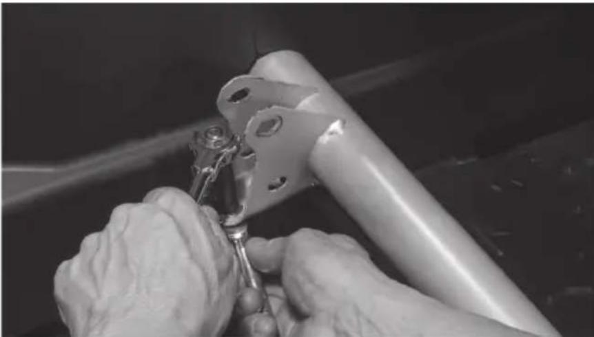
natural_image
Close-up of hands using a tool to adjust or install a metal bracket component (no visible text or symbols)Step 6 - Remove the cable clamp from the brake line.
natural_image
Close-up of hands using a tool to adjust or install a metal component, no visible text or symbolsStep 7 - Wrap the brake line with the strip of adhesive backed foam tape included in the box. Note: This step is to prevent the brake line from rattling against the enclosure under high bass output and any chaffing due to movement of the brake line while the vehicle is in motion.
natural_image
Close-up of hands using a tool to cut or wire down a metal boat (no visible text or symbols)Step 8 - Tilt the front of the enclosure down and slide it under the forward crossbar as you set it in place onto the floor of the vehicle tucking the brake line into the pre-molded slot in the bottom of the enclosure.
natural_image
Person adjusting a black metal frame component on a vehicle chassis (no visible text or symbols)Step 9 - Taking the long bar bracket included, align the slotted holes with the threaded insets on the top rear of the enclosure. The two large holes at either end should slide over the threaded seat mounting posts.
natural_image
Close-up of a mechanical assembly with metal brackets and wiring (no visible text or symbols)Step 10 - Loosely install three (3) T-40 Torx screws into the bracket.
natural_image
Close-up of a mechanical component with three circular annotations pointing to pins, no visible text or symbols.Step 11 - Align the threaded inserts at the front corners of the enclosure with the holes in the bottom of the seat brackets and insert two (2) T-40 Torx screws.
natural_image
Close-up of a mechanical component with a metallic rod inserted into a rectangular housing (no visible text or symbols)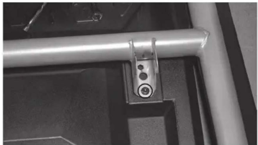
natural_image
Close-up of a metallic mechanical bracket with circular components, mounted on a dark surface (no visible text or symbols)Step 12 - Once all fasteners are in place, tighten to secure the enclosure.
natural_image
Close-up of a hand using a wrench to adjust or install a mechanical component (no visible text or symbols)Step 13 - Route the subwoofer cable to the desired connection point. Note: If installing as part of a kit, the subwoofer plug will connect to the main harness supplied. If not installing as part of a kit, the plug will need to be removed and additional speaker wire added.
Step 14 - With your wire routed and system tested, reinstall the seat in the reverse order as removed. Note: In the event of floor pan rattle, included in the subwoofer kit are a self-tapping drill bit and bolts to allow you to bolt the floor pan directly to the frame of the vehicle. Please refer to the installation videos for more information on their use at www.youtube.com/user/MTXAudioUSA
Step 15 - Reassemble and go ride.
NOTES
WARRANTY PERIOD
At MTX Audio we engineer products that will stand up to the test of time. We also realize that from time to time a problem may occur. That's why our products carry a 2-year limited warranty that begins at the time of sale to the end user.
Of course, we're here to help. If you experience an issue with any of our products within the warranty period, please contact our customer service technical line at 1-800-CALL-MTX to help troubleshoot your issue. If, after speaking with our technical experts it is determined that a problem lies with the product, the technician will provide you with a Return Authorization number and all relevant details you'll need to get the product taken care of.
MITEK WARRANTY
MiTek Mobile products (including, but not limited to: MTX, Coustic, Streetwires, Xtant, BassSlammer, and Thunder Marine) purchased in the USA from an AUTHORIZED MITEK DEALER are guaranteed against defects in material and workmanship for the period of time specified. The warranty period begins the day the product is purchased by the end user, and this warranty is limited to the original retail purchaser of product. Products found to be defective during the warranty period will be repaired or replaced with equivalent product by MiTek at no charge. This warranty is void if it is determined that unauthorized parties have attempted repairs or alterations of any nature, and the warranty does not extend to cosmetics or finish. MiTek disclaims any liability for other incurred or consequential damages resulting from product defects. MiTek's total liability will not exceed the purchase price of the product.

Let's Get Social
mtx.com

natural_image
Four black square icons representing social media platforms: Instagram, Twitter, Facebook, and YouTube (no text or symbols beyond logos)Like, Follow, & Subscribe
© 2021 MiTek Corporation. All rights reserved. MTX is a trademark of MiTek Corporation. All other trademarks are property of their respective owners. Designed and Engineered in the U.S.A.
Due to continual product development, all specifications are subject to change without notice.
MTX Audio, 4545 East Baseline Rd. Phoenix, AZ 85042 U.S.A. 1-800-225-5689
MTX006228 RevA 1/21 • 21A10813 • AW0015868
- Thank You!
- IN THE BOX
- RECOMMENDED TOOLS
- INSTALL VIDEO
- WE'RE HERE TO HELP
- DON'T FORGET TO REGISTER YOUR PRODUCT
- MAKE SURE TO READ THIS
- IMPORTANT NOTICE
- MGX®
- AUDIO
- THANKS AGAIN!
- MX® AUDIO
- THANK YOU
- FIT GUIDE
- INSTALLATION TOOLS
- INSTALLATION
- WARRANTY PERIOD
- MITEK WARRANTY
- NOTES
- Let's Get Social
- mtx.com
- FEATURES
- SPECIFICATIONS
- DRIVER SIDE
- X3-17-SW-D / X3-17-SW-P CAN-AM® MAVERICK X3 SUBWOOFER ENCLOSURE OWNER'S MANUAL ADDENDUM
- NOTICE
- FIT GUIDE NOTES
- MTX®
Brand : MTX Audio
Model : X3-17-Thunder6
Category : Car Radio