A14 - Lens TAMRON - Free user manual and instructions
Find the device manual for free A14 TAMRON in PDF.

User questions about A14 TAMRON
0 question about this device. Answer the ones you know or ask your own.
Ask a new question about this device
Download the instructions for your Lens in PDF format for free! Find your manual A14 - TAMRON and take your electronic device back in hand. On this page are published all the documents necessary for the use of your device. A14 by TAMRON.
USER MANUAL A14 TAMRON
XR DiⅡ LD Aspherical [IF] Macro
Model: A14
2


1 y T
78 en Sis 2:00-1024-igns.28 le, 0 + 1:00? (un-flin); . sen 89-61
Tok de su: "sa a bha-er mnds a ring" was: 2018
Call to: 38609.1 CH [PAC, E, SUTO, OTT [AR, EI] (I)
Gangai, 空洞湖
On nA F to 8: 24 September 19FF [P-65]
In the term, I am to be a time that is the "IIF" option.
变更与注
The CDC Co-forma; Recent application to the Council
Direct to 96/355:EEC, 92/31:EEC, 30/88:EEC and
su#ed by T#ron Co. Ltd. manufacture this
[Unreadable]
Thank you for purchasing the Tamron lens as the latest addition to your photographic equipment. Di II lens (Digitally Integrated) series are designed for digital SLR cameras with image sensors equivalent to APS-C size. Before using your new lens, please read the contents of this Owner's Manual thoroughly to familiarize yourself with your lens and the proper techniques for creating the highest quality images possible. With proper handling and care, your Tamron lens will give you many years of photographing beautiful and exciting pictures.

• Explains precautions that help to prevent problems.
• Explains things you should know in addition to basic operations.
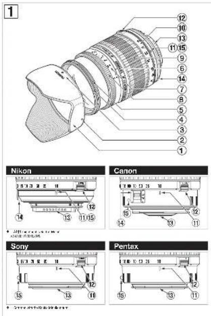
NOMENCLATURE (Refer to Fig. 1, if not specified)
| 1 Lens hood | 2 Hood attaching alignment mark |
| 3 Hood attaching indicator | 4 Filter ring |
| 5 Hood attaching bayonet ring | 6 Distance index |
| 7 Distance scale | 8 Focusing ring |
| 9 Zooming ring | 10 Focal length scale |
| 11 Zoom index mark | 11 Zoom lock switch (Figs. 3) & 4) |
| 13 Lens mount/Lens mount contacts (Nikon) | 14 AF-MF altering switch (Canon, Nikon Fig. 5) & 6) |
SPECIFICATIONS
| Focal Length 18-200 mm | |
| Maximum Aperture F/3.5-6.3 | |
| Angle of View | 75°32' - 759' |
| Lens Construction | 13/15 |
| Minimum Focusing Distance | 0.45 m (1.48') (throughout the entire zoom range) |
| Filter Sizeø | 62 mm |
| Length | 83.7 mm (3.3") |
| Diameterø 73.8 mm (2.9") | |
| Weight | 405 g (14.3 oz) |
| Lens Hood | A006 |

• Lengths and weights listed in lens specifications are for lens with Nikon mount.
- Features and cosmetic designs of lenses listed in this owner's manual may be revised without notice.
ATTACHING AND REMOVING THE LENS (Ref. Figs. 1 & 10)
■How to mount the lens
Removing the rear cap of the lens. Align the Lens attachment mark (15) on the lens barrel with its counterpart on the camera mount and insert the lens. Rotate the lens clockwise until it click-locks. For Nikon models, align the lens attachment mark with the dot on the camera and rotate the lens counter-clockwise until it click-locks.
■How to detach the lens
Pressing the lens release button on the camera down, turn the lens counter-clockwise (in case of Nikon lens, clockwise), and lift the lens off the camera's lens mount.
- The image circles of Di II lenses are designed to match the digital SLR cameras using the image sensors equivalent to APS-C (approx. 15.5×23.2mm). Do not use Di II lenses with cameras using image sensors larger than APS-C. Using Di II lenses with such cameras may cause vignetting on the image.
- Some Canon digital SLR cameras have index marks for attaching both EF lenses (red) Ⓐ and EF-S lenses (white) Ⓑ on the bayonet mount.
To attach Tamron Dill lenses, align the lens attachment mark on the lens (1) with the index mark for EF lenses (red) A. Do not forcibly align the indicator on the lens (2) with the index mark for EF-S lens (white) B.
Doing so could result in damage to the lens and/or camera.
- For further details, please read the instruction manual of your camera.
FOCUSING (Autofocus) (Ref. Figs. 1, 2, 5)
Switch the focusing mode switch of the camera to Auto focusing mode (AF) in case of Sony or Pentax. In case of a Nikon and Canon camera, switch the AF/MF switch ( ) on the lens to AF. (Fig.13). In case of Nikon camera with the focus mode selector dial, set the focus mode to "S" or "C", and then set the AF/MF switch on the lens side ( ) to "AF." Press the shutter button lightly while viewing through the camera's viewfinder, the lens focuses automatically. An in-focus mark will light when lens focuses on the main subject sharply. Press the shutter button further to photograph.

- When set on AF mode, interfering with focusing ring (⑧) may cause serious damage to the lens mechanism.
- The distance scale (⑦) is marked for guidance purposes. The actual focal point may slightly differ from the distance marked on the focal length index.

- For further details, please read the instruction manual of your camera.
FOCUSING (Manual Focus) (Ref. Figs. 1, 2 & 6)
Switch the focusing mode switch of the camera to manual focusing mode (MF) in case of Sony or Pentax. In case of a Nikon, Canon camera, switch the AF/MF switch (S) on the lens to MF. (Fig. 6) In case of Nikon camera with the focus mode selector dial, set the focus mode to "M", and then set the AF/MF switch on the lens side (4) to "MF." Focus manually rotating the focusing ring while viewing through the camera's viewfinder. The main subject in the viewfinder will be sharp when the lens is focused correctly.

- Even in the MF mode, turning focusing ring (8) while pressing the shutter button halfway the focus aid function lamp lights up when the picture is in focus.
- At infinity, make sure the image in the viewfinder appears sharp. The infinity position on A14 is made with certain allowances to insure proper focus under a variety of conditions.
- For further details, please read the instruction manual of your camera.
ZOOMING (Ref. Fig. 2)
Rotate zooming ring (@) of the lens while viewing through the camera's viewfinder and compose your image at the chosen focal length.
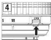
ZOOM LOCK SWITCH (Ref. Figs. 3 & 4)
Model A14 is equipped with zoom lock switch mechanism which prevent lens barrel from extending towards long focal length, while hanging around the neck. Activate the switch at the shortest setting to stop the lens barrels from rotating and extending.
■How to activate the zoom lock switch mechanism
Locking: Set the zoom ring on the lens to the shortest position. Move the zoom lock switch (12) toward the camera for locking the zooming ring (9). The lens barrel is locked in position when the portion beneath "Lock" is shown in red and the lens barrel does not rotate or extend by its own weight.
Releasing: Push the zoom lock switch (12) up. The zooming ring (9) is now released and can be rotated.
- Zoom lock switch can not be activated unless the lens is set to the shortest position. Do not force the lock switch or try to rotate the zooming ring while locked, doing so may damage the lens.
The zoom lock mechanism is made to prevent the lens barrel from extending while carried around the neck. When not locked and the zoom lens may change its focal length during a long exposure used in a low or high angle position.
• The lens can be used at the shortest setting for picture taking even while in the focused position.
LENS APERTURE AND AE MODE
Please follow the instruction manual of your camera.
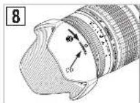
LENS HOOD (Ref. Figs. 1, 7, 8 & 9)
A bayonet-type lens hood is provided as standard equipment. We recommend shooting with the hood attached whenever possible as the lens hood eliminates stray light which is harmful to the picture. However, please be aware of the precautions written below when your camera is equipped with a built-in flash.
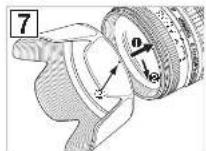
■Attaching the Lens Hood (Ref. Figs. 7 & 8)
Align the index mark (2) on the hood with the corresponding index mark (5) or the top of the index line of the distance scale) on the lens. Press the hood lightly onto the hood attaching bayonet ring (Fig. 7, No. 1) and then rotate it clockwise to secure (Fig. 7, No. 2). The lens hood will be securely held as the mark "TAMRON ○" comes to the top (Fig. 8, No. 3). When attaching the lens hood, hold the focusing and zoom control rings so that they are not rotated unintentionally.
- Pay particular attention to align the hood attaching indexes when using zoom lenses including wide-angle (e.i. 35 mm or wider) settings.
Improper attachment of a hood for wide-angle zoom lens may cause large shadowed areas in your pictures.
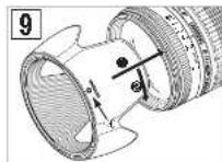
■Stowing lens hood on the lens (Ref. Fig. 9)
Reverse the lens hood. Point the lens toward to opening, then align the hood attachment mark on the lens with the (TAMRON ○)
alignment on the hood (③).
Turn the hood clockwise until it alignment mark (●) is at the top to set it. (Fig.9, 2)
PRECAUTIONS IN SHOOTING
- The optical design for Di II takes into consideration the various features of digital single reflex cameras. However, due to the configuration of the digital single reflex cameras, even when the autofocus accuracy is within specifications, the focal point may be a little forward or behind the optimum point when shooting with auto focus under some conditions.
- When photographing near the minimum focusing distance it is advisable to shoot at higher f-numbers to obtain sharper image quality. - The image circles of Di II lenses are designed to match the digital SLR cameras using the image sensors equivalent to APS-C (approx. 15.5×23.2mm). Do not use Di II lenses with cameras using image sensors larger than APS-C. Using Di II lenses with such cameras may cause vignetting on the image.
(A14) employ an internal focusing (IF) system. Because of the characteristics of this optical design, the angles of view at distances other than infinity are wider than that of the lenses applying an ordinary focusing system.
When the built-in flash on the camera is used, adverse photographic phenomena such as corner illumination fall-off or vignetting at the bottom part of the image may be observed, especially in wide angle ranges. This is due to the inherent limitation of the coverage of the built-in flash, and/or the relative position of the flash to the edge of the lens barrel which causes shadows on the image. It is strongly recommended to use a suitable separate flash unit provided by the camera manufacturer for all flash photography. For further details, please read the "built-in flash" article on the instruction manual of your camera.
- When using the lens in the telephoto focal range, please be careful with the camera shake. Effective way to avoid the camera shake is using an ISO setting of higher numbers. Using a tripod or monopod is also effective.
- When set on AF mode, interfering with focusing ring may cause serious damage to the lens mechanism.
- Certain camera models may indicate the maximum and minimum aperture values of the lens appropriate numbers. This is inherent to the design of the camera and not an indication of an error.
TO ENSURE LONG-TERM SATISFACTION
- Avoid touching the glass element surface. Use a photographic lens cloth or blower to remove dust from the lens element surface. When not using the lens, always place a lens cap on it for protection.
- Use a lens cleaning tissue or lint cloth with a drop of cleaning solution to remove fingerprints or dirt on the glass lens surface with a rotary motion from the center to the edge.
- Use a silicon cloth to clean your lens barrel only
- Mildew is an enemy of your lens. Clean the lens after shooting near water or in any humid place. Store your lens in a clean, cool and dry place. When storing the lens in an lens case, store it with commercially available drying agent such as silica gel, and change the agent occasionally. If you find mildew on your lens, consult an authorized repair shop or nearby photo-graphic store.
- Do not touch the lens-camera interface contacts since dust, dirt and/or stains may cause a contact failure between the lens and camera. - When using your equipment [camera(s) and lens(es)] in an environment where the temperature changes from one extreme to the other, make sure to put your equipment temporarily in a case or a plastic bag for a length of time in order for the equipment to go through a gradual temperature shift.
This will reduce potential equipment trouble.