HDVS-CAM-HDMI-W - Security Camera Atlona - Free user manual and instructions
Find the device manual for free HDVS-CAM-HDMI-W Atlona in PDF.

User questions about HDVS-CAM-HDMI-W Atlona
0 question about this device. Answer the ones you know or ask your own.
Ask a new question about this device
Download the instructions for your Security Camera in PDF format for free! Find your manual HDVS-CAM-HDMI-W - Atlona and take your electronic device back in hand. On this page are published all the documents necessary for the use of your device. HDVS-CAM-HDMI-W by Atlona.
USER MANUAL HDVS-CAM-HDMI-W Atlona
PTZ Camera with HDMI Output
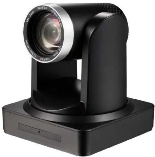
natural_image
Black industrial camera with visible lens and base mount (no text or symbols)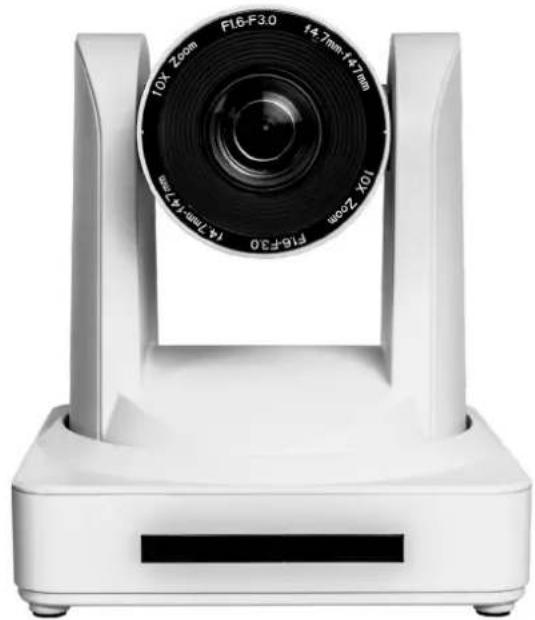
natural_image
White camera lens mounted on a rectangular base, showing aperture and frame numbers (no text or symbols visible)AT-HDVS-CAM-HDMI
Atlona Manuals
Accessories
Version Information
Version Release Date Notes
1 Apr 2020 Initial release
Welcome to Atlona!
Thank you for purchasing this Atlona product. We hope you enjoy it and will take an extra few moments to register your new purchase.
Registration only takes a few minutes and protects this product against theft or loss. In addition, you will receive notifications of product updates and firmware. Atlona product registration is voluntary and failure to register will not affect the product warranty.
To register your product, go to http://www.atlona.com/registration
Sales, Marketing, and Customer Support
Main Office
Atlona Incorporated
70 Daggett Drive
San Jose, CA 95134
United States
Office: +1.877.536.3976 (US Toll-free)
Office: +1.408.962.0515 (US/International)
Sales and Customer Service Hours
Monday - Friday: 6:00 a.m. - 4:30 p.m. (PST)
http://www.atlona.com/
International Headquarters
Atlona International AG
Ringstrasse 15a
8600 Dübendorf
Switzerland
Office: +41 43 508 4321
Sales and Customer Service Hours
Monday - Friday: 09:00 - 17:00 (UTC +1)
Operating Notes
As of this writing, there are no firmware updates for this product. When new firmware is released, update instructions will be included with the firmware and will be appended to this manual.

IMPORTANT: Visit http://www.atlona.com/product/AT-HDVS-CAM-HDMI for the latest firmware updates and User Manual.
Atlona, Inc. ("Atlona") Limited Product Warranty
Coverage
Atlona warrants its products will substantially perform to their published specifications and will be free from defects in materials and workmanship under normal use, conditions and service.
Under its Limited Product Warranty, Atlona, at its sole discretion, will either:
- repair or facilitate the repair of defective products within a reasonable period of time, restore products to their proper operating condition and return defective products free of any charge for necessary parts, labor and shipping.
OR
- replace and return, free of charge, any defective products with direct replacement or with similar products deemed by Atlona to perform substantially the same function as the original products.
OR
- refund the pro-rated value based on the remaining term of the warranty period, not to exceed MSRP, in cases where products are beyond repair and/or no direct or substantially similar replacement products exist.
Repair, replacement or refund of Atlona products is the purchaser's exclusive remedy and Atlona liability does not extend to any other damages, incidental, consequential or otherwise.
This Limited Product Warranty extends to the original end-user purchaser of Atlona products and is non-transferrable to any subsequent purchaser(s) or owner(s) of these products.
Coverage Periods
Atlona Limited Product Warranty Period begins on the date of purchase by the end-purchaser. The date contained on the end-purchaser 's sales or delivery receipt is the proof purchase date.
Limited Product Warranty Terms - New Products
• 10 years from proof of purchase date for hardware/electronics products purchased on or after June 1, 2013.
• PTZ motor is not covered under the 10 year warranty, the PTZ motor is covered for 3 years.
• 3 years from proof of purchase date for hardware/electronics products purchased before June 1, 2013.
• Lifetime Limited Product Warranty for all cable products.
Limited Product Warranty Terms - Refurbished (B-Stock) Products and Discontinued Products
- 3 years from proof of purchase date for all Refurbished (B-Stock) and Discontinued hardware and electronic products purchased on or after June 1, 2013.
Remedy
Atlona recommends that end-purchasers contact their authorized Atlona dealer or reseller from whom they purchased their products. Atlona can also be contacted directly. Visit www.atlona.com for Atlona's contact information and hours of operation. Atlona requires that a dated sales or delivery receipt from an authorized dealer, reseller or end-purchaser is provided before Atlona extends its warranty services. Additionally, a return merchandise authorization (RMA) and/or case number, is required to be obtained from Atlona in advance of returns.
Atlona requires that products returned are properly packed, preferably in the original carton, for shipping. Cartons not bearing a return authorization or case number will be refused. Atlona, at its sole discretion, reserves the right to reject any products received without advanced authorization. Authorizations can be requested by calling 1-877-536-3976 (US toll free) or 1-408-962-0515 (US/international) or via Atlona's website at www.atlona.com.
Exclusions
This Limited Product Warranty excludes:
- Damage, deterioration or malfunction caused by any alteration, modification, improper use, neglect, improper packaging or shipping (such claims must be presented to the carrier), lightning, power surges, or other acts of nature.
Atlona, Inc. ("Atlona") Limited Product Warranty
- Damage, deterioration or malfunction resulting from the installation or removal of this product from any installation, any unauthorized tampering with this product, any repairs attempted by anyone unauthorized by Atlona to make such repairs, or any other cause which does not relate directly to a defect in materials and/or workmanship of this product.
- Equipment enclosures, cables, power supplies, batteries, LCD displays, and any accessories used in conjunction with the product(s).
- Products purchased from unauthorized distributors, dealers, resellers, auction websites and similar unauthorized channels of distribution.
Disclaimers
This Limited Product Warranty does not imply that the electronic components contained within Atlona's products will not become obsolete nor does it imply Atlona products or their electronic components will remain compatible with any other current product, technology or any future products or technologies in which Atlona's products may be used in conjunction with. Atlona, at its sole discretion, reserves the right not to extend its warranty offering in instances arising outside its normal course of business including, but not limited to, damage inflicted to its products from acts of god.
Limitation on Liability
The maximum liability of Atlona under this limited product warranty shall not exceed the original Atlona MSRP for its products. To the maximum extent permitted by law, Atlona is not responsible for the direct, special, incidental or consequential damages resulting from any breach of warranty or condition, or under any other legal theory. Some countries, districts or states do not allow the exclusion or limitation of relief, special, incidental, consequential or indirect damages, or the limitation of liability to specified amounts, so the above limitations or exclusions may not apply to you.
Exclusive Remedy
To the maximum extent permitted by law, this limited product warranty and the remedies set forth above are exclusive and in lieu of all other warranties, remedies and conditions, whether oral or written, express or implied. To the maximum extent permitted by law, Atlona specifically disclaims all implied warranties, including, without limitation, warranties of merchantability and fitness for a particular purpose. If Atlona cannot lawfully disclaim or exclude implied warranties under applicable law, then all implied warranties covering its products including warranties of merchantability and fitness for a particular purpose, shall provide to its products under applicable law. If any product to which this limited warranty applies is a “Consumer Product” under the Magnuson-Moss Warranty Act (15 U.S.C.A. §2301, ET SEQ.) or other applicable law, the foregoing disclaimer of implied warranties shall not apply, and all implied warranties on its products, including warranties of merchantability and fitness for the particular purpose, shall apply as provided under applicable law.
Other Conditions
Atlona's Limited Product Warranty offering gives legal rights, and other rights may apply and vary from country to country or state to state. This limited warranty is void if (i) the label bearing the serial number of products have been removed or defaced, (ii) products are not purchased from an authorized Atlona dealer or reseller. A comprehensive list of Atlona's authorized distributors, dealers and resellers can be found at www.atlona.com.
Important Safety Information
CAUTION
RISK OF ELECTRIC SHOCK
DO NOT OPEN
CAUTION: TO REDUCT THE RISK OF
ELECTRIC SHOCK
DO NOT OPEN ENCLOSURE OR EXPOSE
TO RAIN OR MOISTURE
NO USER-SERVICEABLE PARTS
INSIDE REFER SERVICING TO
QUALIFIED SERVICE PERSONNEL.

The exclamation point within an equilateral triangle is intended to alert the user to the presence of important operating and maintenance instructions in the literature accompanying the product.

The information bubble is intended to alert the user to helpful or optional operational instructions in the literature accompanying the product.
- Read these instructions.
- Keep these instructions.
- Heed all warnings.
- Follow all instructions.
- Do not use this product near water.
- Clean only with a dry cloth.
- Do not block any ventilation openings. Install in accordance with the manufacturer's instructions.
-
Do not install or place this product near any heat sources such as radiators, heat registers, stoves, or other apparatus (including amplifiers) that produce heat.
-
Do not defeat the safety purpose of a polarized or grounding-type plug. A polarized plug has two blades with one wider than the other. A grounding type plug has two blades and a third grounding prong. The wide blade or the third prong are provided for your safety. If the provided plug does not fit into your outlet, consult an electrician for replacement of the obsolete outlet.
- Protect the power cord from being walked on or pinched particularly at plugs, convenience receptacles, and the point where they exit from the product.
- Only use attachments/accessories specified by Atlona.
- To reduce the risk of electric shock and/or damage to this product, never handle or touch this unit or power cord if your hands are wet or damp. Do not expose this product to rain or moisture.
- Unplug this product during lightning storms or when unused for long periods of time.
- Refer all servicing to qualified service personnel. Servicing is required when the product has been damaged in any way, such as power-supply cord or plug is damaged, liquid has been spilled or objects have fallen into the product, the product has been exposed to rain or moisture, does not operate normally, or has been dropped.


FCC Statement

text_image
FCFCC Compliance and Advisory Statement: This hardware device complies with Part 15 of the FCC rules. Operation is subject to the following two conditions: 1) this device may not cause harmful interference, and 2) this device must accept any interference received including interference that may cause undesired operation. This equipment has been tested and found to comply with the limits for a Class A digital device, pursuant to Part 15 of the FCC Rules. These limits are designed to provide reasonable protection against harmful interference in a commercial installation. This equipment generates, uses, and can radiate radio frequency energy and, if not installed or used in accordance with the instructions, may cause harmful interference
to radio communications. However there is no guarantee that interference will not occur in a particular installation. If this equipment does cause harmful interference to radio or television reception, which can be determined by turning the equipment off and on, the user is encouraged to try to correct the interference by one or more of the following measures: 1) reorient or relocate the receiving antenna; 2) increase the separation between the equipment and the receiver; 3) connect the equipment to an outlet on a circuit different from that to which the receiver is connected; 4) consult the dealer or an experienced radio/TV technician for help. Any changes or modifications not expressly approved by the party responsible for compliance could void the user's authority to operate the equipment. Where shielded interface cables have been provided with the product or specified additional components or accessories elsewhere defined to be used with the installation of the product, they must be used in order to ensure compliance with FCC regulations.
Table of Contents
Introduction 8
Features 8
Package Contents 8
Panel Description 9
Installation
10
Connection Instructions 10
Mounting Instructions 10
Connection Diagram 12
Basic Operation 13
Home Position 13
Field of View 14
Sample Calculations Table 14
Calculating Specific Values 15
Controlling the Camera 16
Tilt 16
Pan (Rotation) 16
Tilt and Pan Combinations 17
Zoom 18
Focus 18
Backlight Compensation (BLC) 19
Standby Mode 19
Managing Presets 20
Saving Presets 20
Clearing a Preset 20
Recalling Presets 20
Function List 21
WebGUI
22
IR Remote and OSD
IR Remote Control 34
OSD 34
Remote Functions 36
Appendix
37
Specifications 37
Introduction
The Atlona AT-HDVS-CAM-HDMI is an enterprise-grade PTZ camera designed for use in video conferencing and other applications such as lecture capture and distance education. It features HDMI output, as well as a USB 2.0 interface for video and camera control. Simultaneous video output is available through two interfaces. Through USB, the HDVS-CAM-HDMI seamlessly integrates with the Omega™ Series for a complete, automated conferencing system that includes AV and USB extension. The HDMI output is ideal for use with a video conferencing codec, lecture capture appliance, or PC equipped for video capture. The HDVS-CAM-HDMI delivers high performance, professional-quality imaging with video resolutions up to 1080p @ 60 Hz over HDMI and 1080p @ 30 Hz for USB 2.0, as well as fast and accurate auto-focusing, and a fast yet quiet pan and tilt mechanism. This PTZ camera is ideal for a wide range of small to medium-sized meeting spaces, classrooms, training rooms, and many other environments. The HDVS-CAM-HDMI is available in black or white.
Features
- Designed for video conferencing and other applications such as lecture capture and distance education
- HDMI output
• USB 2.0 interface for video and camera control
• Simultaneous video output over HDMI and USB
• Universal PC compatibility through standard UVC (USB Video Class) driver - PTZ camera control available from popular soft codec and UC clients such as Microsoft® Teams, Zoom™, Blue-Jeans™, Slack™, WebEx®, and GoToMeeting®
- Up to 255 camera presets available, 10 accessible from IR remote
• Supports VISCA, Pelco-D, and Pelco-P camera control protocols - Fast and accurate auto focus, plus auto white balance and auto exposure modes
• Picture controls available for brightness, color, saturation, contrast, sharpness, and gamma - Easy, GUI-based configuration using integrated web server
- TCP/IP, RS-232, USB, and IR control – convenient handheld IR remote control included
• Delivers HD video resolutions including 1080p @ 60 Hz (176x144 up to 1080p @ 30 Hz over USB 2.0)
• High performance imaging, fine detail, and color rendering with 1/2.8" low-noise, HD CMOS sensor - Multi-element zoom lens with 10x optical zoom and a 60.9^ horizontal field of view
- Camera can be mounted on a wall, or inverted for ceiling installation with the optional AT-HDVS-CAM-CMNT ceiling mount kit
- Includes installation guide, wall mounting bracket, IR remote control, 2 meter (6.5 foot) USB Type-A male to male cable, VISCA to RS-232 DB-9 adapter, lens cap, and external universal power supply
• Available in black or white
• Three-year limited product warranty
Package Contents
1 x AT-HDVS-CAM-HDMI-BK or AT-HDVS-CAM-HDMI-WH
1 x Wall mounting plate
1 x 1/4 20OUNC screws
1 x IR Remote Control
1 x USB A cable
1 x VISCA to RS-232 DB-9 adapter
2 x AAA battery
1 x Installation Guide
Panel Description
Front (AT-HDVS-CAM-HDMI-WH shown)
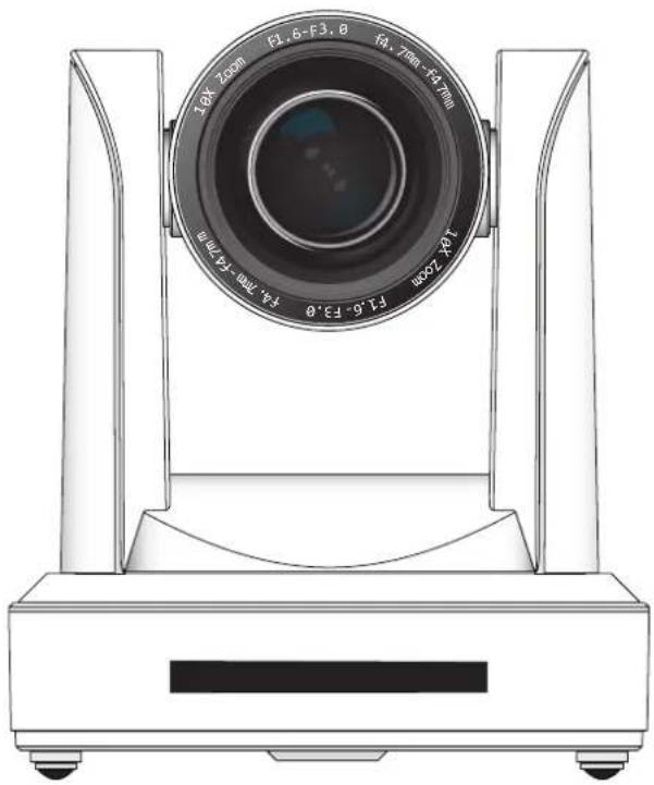
natural_image
Technical line drawing of a camera lens mounted on a base (no text or symbols)Back (AT-HDVS-CAM-HDMI-BK shown)
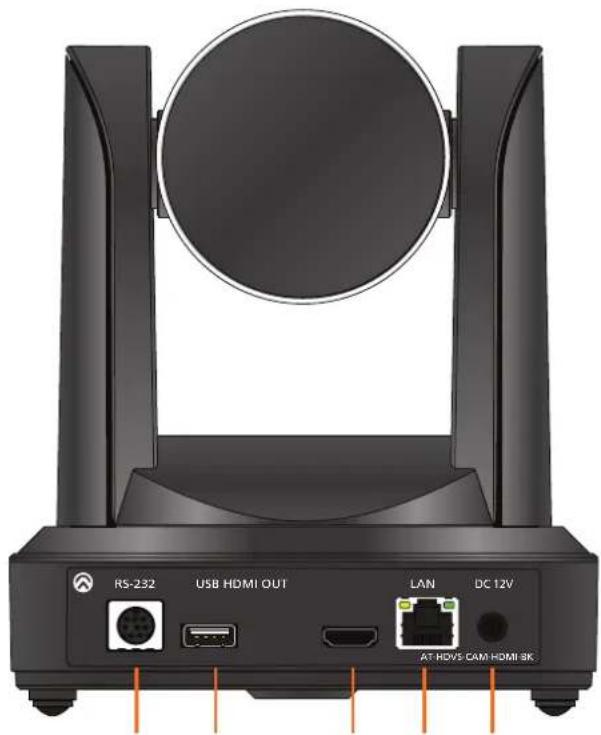
natural_image
Front view of a black wireless router device with ports and connectors (no visible text or symbols on the device body)1 32 4 5
1. RS-232
Connect included VISCA to RS-232 adapter here to control the camera with a third party software or hardware controller.
2. USB
Connect USB A cable from this port to the USB port of a conferencing system or USB extender such as AT-OME-EX-RX, AT-OME-SR21, etc.
3. HDMI OUT
Connect to an HDMI device such as a video conference codec or PC.
4. LAN
Connect to a network switch to control the unit via TCP/IP or webGUI.
5. DC 12V
Connect the included 12V power supply to this port.
Installation
Connection Instructions
- Connect the included DC 12V power cable to the AT-HDVS-CAM-HDMI.
- Connect the Ethernet cable to the LAN port on the back of the AT-HDVS-CAM-HDMI.
- Connect the USB port of a conferencing system or USB extender such as AT-OME-EX-RX.
- Connect to an HDMI cable from the HDMI port to a video conference codec or PC.
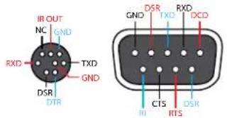
- *Optional* Connect the Visca to RS-232 cable to the Visca port for RS-232 control. Note that RS-232 can also be connected to an AT-OME-RX11 or other receiver that supports RS-232 for remote control.
Visca
Visca RS-232
text_image
IR OUT NC GND RXD TXD GND DSR DTR DSR RXD DCD GND TXD CTS RTSRS-232
flowchart
graph TD
    A["DTR"] --> B["DSR"]
    B --> C["TXD"]
    C --> D["GND"]
    D --> E["RXD"]
    E --> F["GND"]
    F --> G["IR OUT"]
    G --> H["NC"]
    I["DCR"] --> J["RXD"]
    J --> K["TXD"]
    K --> L["GND"]
    L --> M["DSR"]
    M --> N["RTS"]
    N --> O["CTS"]
    O --> P["RI"]

IMPORTANT: Never disconnect power from the USB host device during operation. Disconnecting the power from the USB host can cause video instability.
Mounting Instructions
The AT-HDVS-CAM-HDMI has two installation options, wall mount (included) and ceiling mount (purchased separately).
Wall Mount installation
Install the AT-HDVS-CAM-HDMI, 4 M6 swelling bolts, 1 1/4 20 UNC bolt, 4 M6 nuts & shims, the included wall mount bracket, and the AT-HDVS-CAM-HDMI are needed.
- Install the M6 swelling bolts in a rectangular pattern on the wall, 100 mm wide and 50 mm high.
- Attached the wall mount bracket onto the wall, by placing them on the M6 swelling bolts and securing it with the M6 nuts and shims.
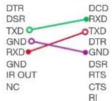
- Once the wall mount bracket is secure on the wall, place the camera on the top of the wall mount bracket and secure it with the 1/4 20 UNC bolt.

natural_image
Pure diagram of three vertical bars with dots, no text or symbols present
natural_image
Isometric line drawing of a device with labeled components and directional arrows (no text or symbols)
natural_image
Technical line drawing of a mechanical assembly with a cylindrical component mounted on a platform (no text or symbols visible)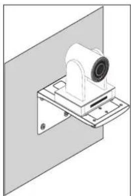
natural_image
Technical line drawing of a mechanical assembly mounted on a wall-mounted platform (no text or symbols)Installation
Ceiling Mount installation
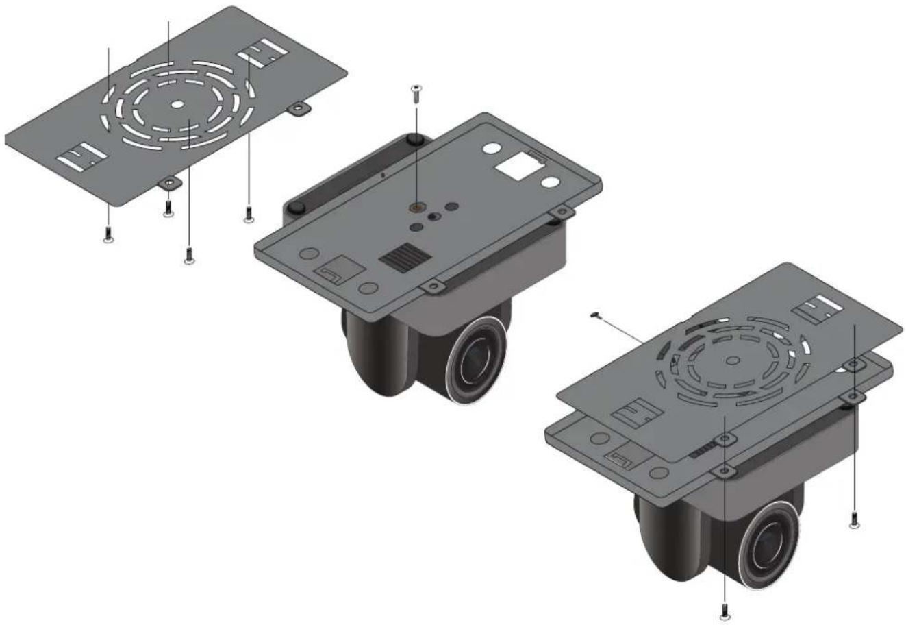
To install the AT-HDVS-CAM-HDMI, 4 PA3X30 self-tapping screws, 4 PM3X6 screws, 4 screw stoppers, 1 1/4 20 UNC screw, the optional ceiling upper and lower covering plates, and the AT-HDVS-CAM-HDMI are needed.
- Install the 4 screw stoppers in the ceiling.
- Connect the upper ceiling covering plate to the screw stoppers using the PA3X30 self-tapping screws.
- Connect the lower ceiling covering plate to the bottom of the AT-HDVS-CAM-HDMI using the 1/4 20 UNC screw.
- Mount the lower ceiling covering plate to the upper ceiling plate using 3 PM3X6 bolts.
natural_image
Exploded view diagram of a three-part electronic device showing internal components and mounting points (no text or symbols)
NOTE: The camera picture will need to be inverted for video to be viewed correctly.
Installation
Connection Diagram
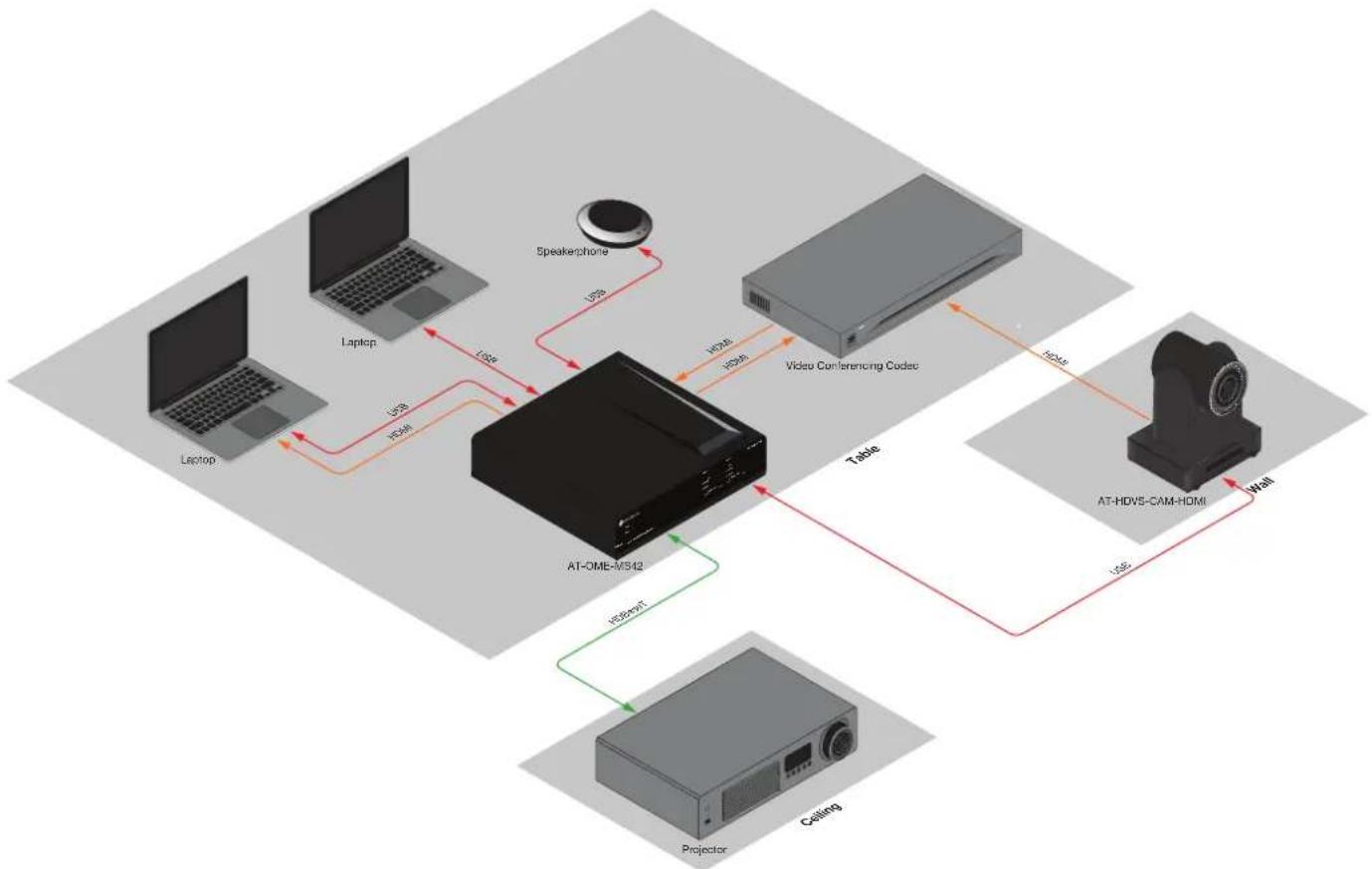
flowchart
graph TD
    A["Laptop"] -->|USB 150Hz| B["Speakerphone"]
    C["Laptop"] -->|USB 150Hz| B
    D["Table"] -->|USB 150Hz| E["Video Conferencing Codec"]
    F["AT-HDV5-CAM-HDMI"] -->|USB 150Hz| B
    G["Projection"] -->|USB 150Hz| B
    H["Ceiling"] -->|USB 150Hz| B
    B --> I["AT-OME-MS42"]
    I --> J["Speakerphone"]
    I --> K["Video Conferencing Codec"]
    I --> L["AT-HDV5-CAM-HDMI"]
    L --> M["Wall"]
Basic Operation
Home Position
"Home" position is a term that is used throughout this manual. When the AT-HDVS-CAM-HDMI is in home position, the camera is facing forward and has no tilt angle, as shown in the illustration below:
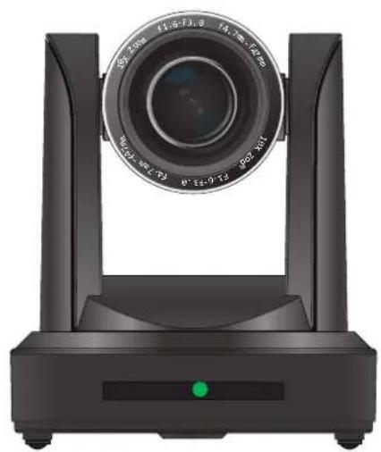
natural_image
Black industrial camera with dual-mounted frame and central lens (no visible text or symbols)Front Left Side
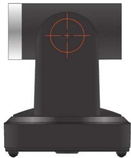
natural_image
3D rendered mechanical component with red crosshair and circular target (no text or symbols)Field of View
When positioning the camera in a huddle room or similar area, it will be helpful to know the viewing area of the camera, based on a fixed target. The viewable area of the camera is called the linear field of view or sometimes referred to as the image plane.
The illustration below shows the AT-HDVS-CAM-HDMI pointed at a fixed target.
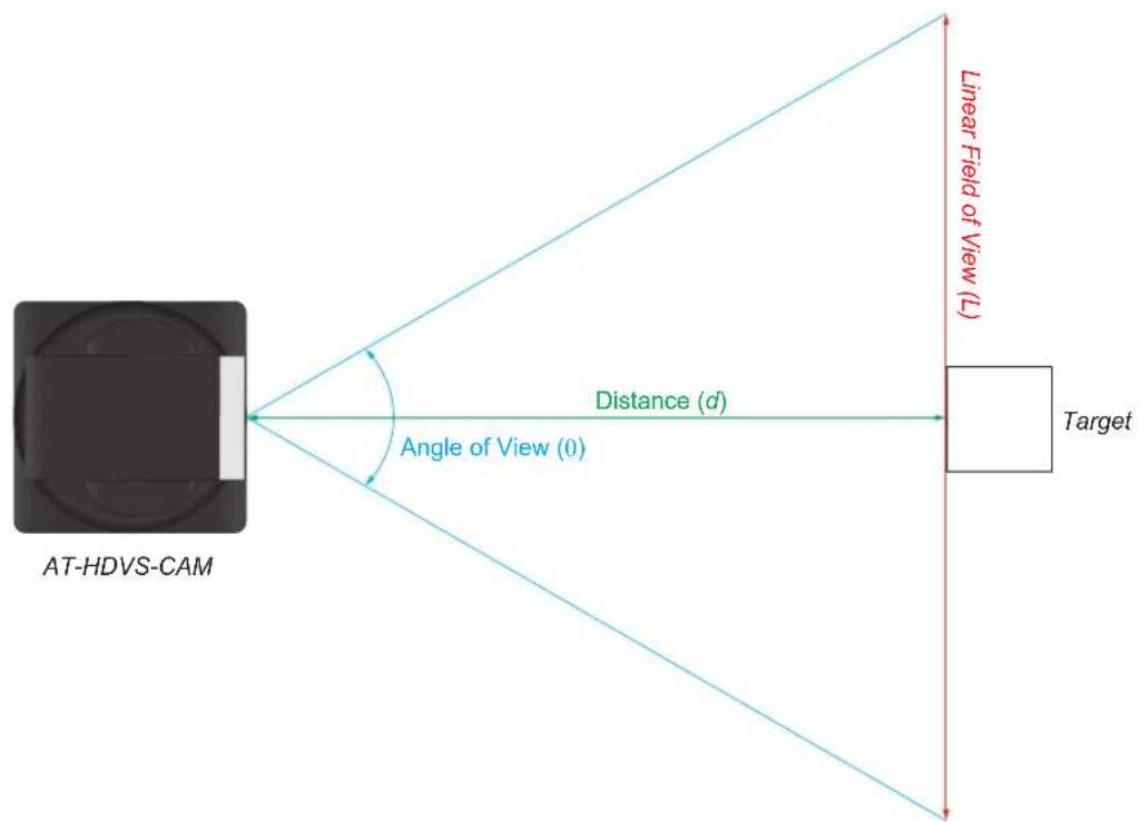
text_image
AT-HDVS-CAM Distance (d) Angle of View (0) Linear Field of View (L) TargetSample Calculations Table
The following table provides a list of predefined distances, which the camera must be placed from the target, in order to capture the required Linear Field of View (L). The Angle of View, for the camera, has been set to 60.9^ (wide-angle).
To calculate custom values, refer to Calculating Specific Values (page 15).
| Angle of View (θ), in degrees | Distance (d), in feet | Linear Field of View (L), in feet |
| 60.9° 5 5.875076864 | ||
| 10 11.75015373 | ||
| 15 17.62523059 | ||
| 20 23.50030746 | ||
| 25 29.37538432 |
Calculating Specific Values
In order to calculate custom values, this section introduces some trigonometric formulas which can be used to find the Linear Field of View (L), Distance (d), or the Angle of View (0). The derivation of each formula is beyond the scope of this manual. As long as any two values are known, the third value can be calculated as follows:
Linear Field of View (FOV) Angle of View Distance to target
$$ L = 2 \cdot d \cdot \tan (\frac {\theta}{2}) $$
$$ \theta = 2 \cdot \arctan (\frac {L}{2 \cdot d}) $$
$$ d = \frac {L}{2 \cdot t a n (\frac {\theta}{2})} $$

NOTE: When calculating the Angle of View, using a calculator that is set to radians, multiply the result by 180 to convert the answer to degrees. The value of can be approximated as 3.1415.
Example
In the following diagram, the camera angle of view is set to 54.7^ . The viewing area to be captured is measured to be 9 feet. How far from the target must the camera be placed in order to capture this area?
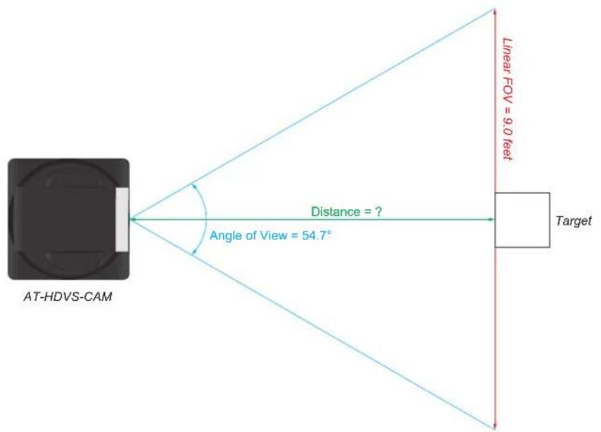
text_image
AT-HDVS-CAM Distance = ? Angle of View = 54.7° Linear FGV = 9.0 feet Target-
Use the following formula: d = 2 · tan(2)
-
Substitute the known values for each variable in the equation. In this case, we know both the linear FOV and the angle of view. Therefore:
$$ L = 9 $$
$$ \theta = 5 4. 7 $$
-
The equation becomes: d = 92 · (54.72)
-
(54.72)=0.5172
-
Multiplying this result by 2 gives: 1.0344
-
Dividing 9 by 1.0344, yields: 8.700. Therefore, the camera must be placed 8.7 feet from the target.
Controlling the Camera
The AT-HDVS-CAM-HDMI can be controlled using the included IR remote control, RS-232, TCP/IP, or through the webGUI. Refer to the WebGUI (page 22) for more information about accessing the webGUI.
Tilt
The camera tilt range is approximately -45 degrees to +90 degrees. Use one of the following methods to adjust the camera tilt.

natural_image
Diagram of a mechanical component with a curved arrow indicating rotation or force direction (no text or symbols)IR Remote Control
- Press and release the up or down arrow button to adjust the tilt of the camera in small increments.
- Press and hold the up or down arrow button to adjust the camera tilt at a faster rate.
- Press the HOME button to return the camera to the "home" position.

text_image
SET PRESET CLEAR PRESET HOME BLC ON/OFF MENU Tilt up Tilt downwebGUI
- Click Control in the side menu bar.
- Click the up-arrow or down-arrow button to tilt the camera up or down, respectively.
- Click the 📁icon in the center to return the camera to the "home" position.

text_image
Tilt up Tilt downPan (Rotation)
The camera pan range is approximately 360 degrees. Use one of the following methods to adjust the camera pan.

text_image
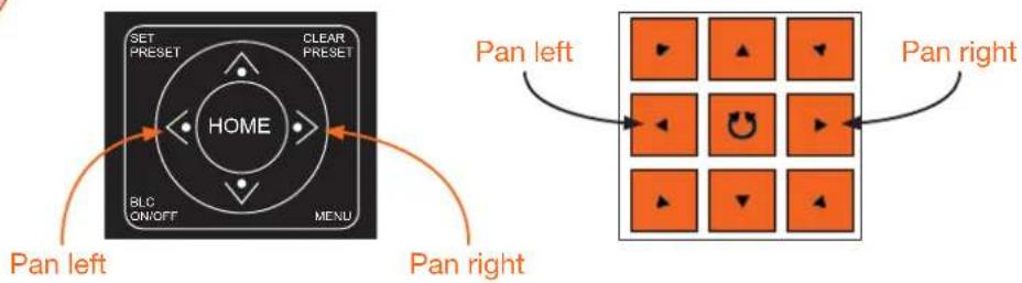
FrontIR Remote Control
- Press and release the left or right arrow button to adjust the camera tilt in small increments.
- Press and hold the left-arrow or right-arrow button to adjust the camera tilt at a faster rate.
- Press the HOME button to return the camera to the "home" position.
webGUI
- Click Control in the side menu bar.
- Click the left arrow or right arrow button to tilt the camera up or down, respectively.
- Click the 📁con in the center to return the camera to the "home" position.
text_image
SET PRESET CLEAR PRESET HOME BLC ON/OFF MENU Pan left Pan right Pan left Pan rightTilt and Pan Combinations
The webGUI provides a method for combining both tilt and pan motion. Note that this function is not available on the included IR Remote Control.
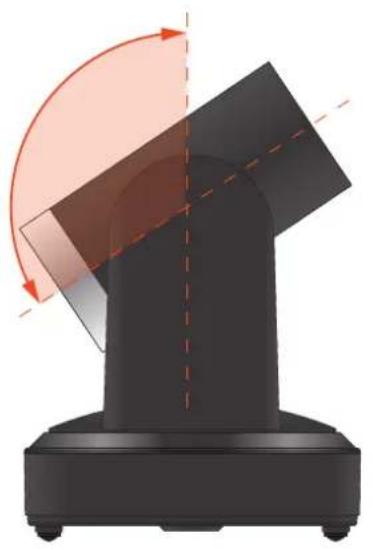
natural_image
3D diagram of a mechanical component with curved arrows indicating rotation or force direction (no text or symbols)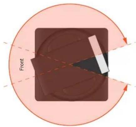
text_image
Front
flowchart
graph TD
    A["Left: Pan + tilt up"] --> B["Grid with arrows indicating direction"]
    C["Right: Pan + tilt up"] --> B
    D["Left: Pan + tilt down"] --> B
    E["Right: Pan + tilt down"] --> B
    B --> F["Arrow indicating rotation or clockwise direction"]
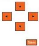
webGUI (only)
- Click Control in the side menu bar.
- Click the diagonal arrow buttons to simultaneously tilt and pan the camera in the desired direction:
• Upper Diagonal-left arrow
Pans and rotates camera up and to the left.
• Lower Diagonal-left arrow
Pans and rotates camera down and to the left.
• Upper Diagonal-right arrow
Pans and rotates camera up and to the right.
• Lower Diagonal-right arrow
Pans and rotates camera down and to the right.
- Click the 📁con in the center to return the camera to the "home" position.
Zoom
The camera is provides a zoom factor up to 10x. Use one of the following methods to adjust the camera zoom.
IR Remote Control
- Locate the ZOOM rocker switch on the IR Remote Control.
- Press and release + to zoom-in or press - to zoom-out.
- Press and hold the these buttons to zoom-in or zoom-out at a faster rate.
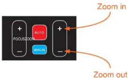
text_image
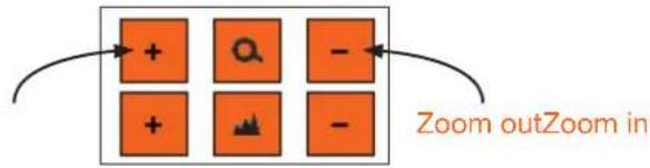
FOCUSZOOM AUTO MUAL Zoom in Zoom outwebGUI
- Click Control in the side menu bar.
- Click + to zoom-in or click - to zoom out.
flowchart
graph TD
    A["+"] --> B["+"]
    C["Q"] --> D["+"]
    E["-"] --> F["-"]
    G["Zoom outZoom in"] --> H["->"]
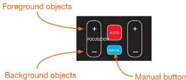
Focus
When positioning the camera on an object, it may be necessary to adjust the focus for a clear image. The AT-HDVS-CAM-HDMI can be set to auto focus or manual focus. By default, the AT-HDVS-CAM-HDMI is set to auto-focus mode.

NOTE: In order to manually control the focus, the AT-HDVS-CAM-HDMI must be in manual focus mode. Press the MANUAL button to enter manual focus mode.
IR Remote Control
- Press and release the MANUAL button.
- Locate the FOCUS rocker switch on the IR Remote Control.
- Press and release + to increase focus on objects in the foreground. Press and release the - to focus on objects in the background.
- Press and hold the these buttons to adjust the focus at a faster rate.
text_image
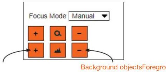
Foreground objects + AUTO FOCUSZOOM - MANUAL - Manual buttonwebGUI
- Click Control in the side menu bar.
- Set the AT-HDVS-CAM-HDMI to manual focus mode by selecting Manual from the Focus Mode drop-down list.
- Click + to focus on foreground objects or click - to focus on background objects.
text_image
Focus Mode Manual + - + - Background objectsForegroBacklight Compensation (BLC)
BLC is a feature which automatically adjusts the exposure control of the camera. When enabled, BLC will attempt to increase the ambient foreground light and “darken” any background light. For example, a subject standing in front of a window in the daytime, will produce a silhouetted effect. Enabling BLC will compensate for the difference in lighting.
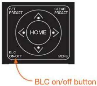
IR Remote Control
- Point the IR Remote Control at the front of the AT-HDVS-CAM-HDMI.
- Press and release the BLC ON/OFF button to toggle BLC on or off.
text_image
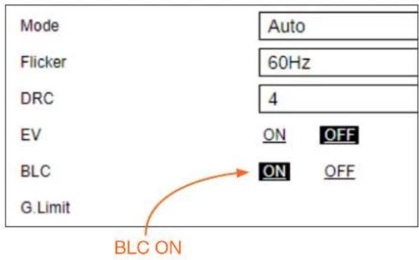
SET PRESET CLEAR PRESET HOME BLC ON/OFF MENU BLC on/off buttonwebGUI
- Click Exposure in the side menu bar.
- Click ON to enable BLC. Click OFF to disable BLC.
text_image
Mode Auto Flicker 60Hz DRC 4 EV ON OFF BLC ON OFF G.Limit BLC ONStandby Mode
Placing the AT-HDVS-CAM-HDMI in standby mode will power-down the camera. Placing the camera in standby mode is managed using the IR Remote Control.
- Point the IR Remote Control at the front of the AT-HDVS-CAM-HDMI.
- Press and hold the ⏻ button for three seconds.
- The camera will rotate 90 degrees and the camera lens assembly will tilt approximately 45 degrees. The camera is now in standby mode.
- Press and hold the ⏻ button for three seconds to wake the camera. After the camera is awake, it will return to the home position.

text_image
Power button SET CAMERA SELECT 1 2 3 4 1 2 3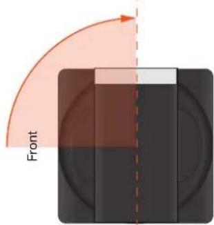
text_image
Front
NOTE: The camera will always be set to the home position after this sequence is performed. To return the camera to the last position, either position it manually or recall the saved preset.
Managing Presets
Camera positions can be stored to local memory and recalled at a later time. Presets are stored and recalled using the included IR Remote Control. Up to 10 presets can be saved.
Saving Presets
- Set the camera in the desired position.
- Point the IR Remote Control at the front of the AT-HDVS-CAM-HDMI.
- Press the SET PRESET button.
- Press the desired number on the IR Remote Control keypad to assign the position of the camera to the preset.

text_image
1 2 3 4 5 6 7 8 9 * 8 # + AUTO + FOCUS/COM MANUAL - - SET PRESET CLEAR PRESET HOME BLC ON/OFF MENU Keypad Clear Preset button Set Preset buttonClearing a Preset
Presets can be erased. It is not necessary to clear a preset, before saving a new camera position in the same preset. If a preset is saved to an existing preset, it will be overwritten.
- Press the CLEAR PRESET button.
- Press the desired number on the IR Remote Control keypad to clear the preset.

NOTE: To clear all presets, press and release the [#] key on the keypad, three times.
Recalling Presets
- Point the IR Remote Control at the front of the AT-HDVS-CAM-HDMI.
- Press the number of the desired preset from the IR Remote Control keypad.
- The camera will be set to the position defined by the preset.
Function List
The included IR Remote Control provides a set of functions which can be used to change the behavior of the AT-HDVS-CAM-HDMI. Each function is invoked by sequentially pressing the following series of keys on the keypad.
| Function Keystrokes | |
| Clear all presets [#] + [#] + [#] | |
| Flip video horizontally and vertically [*] + [#] + [9] | |
| Reset username, password, and IP address [*] + [#] + [MANUAL] | |
| Switch video format to 1080p60 [#] + [#] + [0] | |
| Switch video format to 1080p50 [#] + [#] + [1] | |
| Switch video format to 1080i60 [#] + [#] + [2] | |
| Switch video format to 1080i50 [#] + [#] + [3] | |
| Switch video format to 720p60 [#] + [#] + [4] | |
| Switch video format to 720p50 [#] + [#] + [5] | |
| Switch video format to 1080p30 [#] + [#] + [6] | |
| Switch video format to 1080p25 [#] + [#] + [7] | |
| Switch video format to 720p30 [#] + [#] + [8] | |
| Switch video format to 720p25 [#] + [#] + [9] | |
WebGUI
The AT-HDVS-CAM-HDMI includes a built-in webGUI, which allows easy management and control of all features. Follow the instructions below to access the webGUI.
- Use an IP scanner to determine the IP address of the AT-HDVS-CAM-HDMI.
- Launch a web browser.
- In the address bar, type the IP address of the AT-HDVS-CAM-HDMI.
- Enter the following information on the Login page.
Login: admin
Password: Atlona
- Click the Login button. If using a secure connection, click the Toggle HTTP/HTTPS button.

text_image
ATLONA a PAYOUlt company Admin Login User Name: admin Password: ******** Login Clear 1.877.536.3976 - atlona.com - +41.43.508.4321 Pages: 0134000000 Sides: Print- After logging in for the first time, the webGUI will prompt to change the password. Follow the on-screen instructions to change the password.
- The status page will display, giving all the general information of the AT-HDVS-CAM-HDMI.


text_image
Home • Status • Firmware Device Settings • System • Network • User • Reset Visual Settings • Picture • Focus • Exposure • Noise Reduction • Style • Event System Information Model AF HDVS-CAM-HDMI MAC Address B8.98.B0.62.S1.02 Serial Number 102290 MCU Firmware V3.1.2 Camera Firmware V2.5.7 AP Firmware V4.0.2- Select firmware from the side menu.

text_image
ATLONA a PNC 4 company Home • Status • Firmware Device Settings • System • Network • Use • Reset Visual Settings • Picture • Focus • Experience • Noise Reduction • Style • OSD • Vens Dot Camera • Control Firmware Status System MCU V3.1.2 Camera V2.5.7 Auto-Focus V4.0.2 Check for the most recent firmware update! Firmware Update Update Files Dream UploadsFirmware Status
MCU - Displays the current OSD software.
Camera - Displays the current unit software.
Auto Focus - Displays the software for auto focus.
Firmware Update
Browse - Select browse and search the local computer for the firmware.
Update - Load the selected file to the unit.
9. Select System from the side menu.

ATLONA
a PANOUIT company
Home
- Status
- Firmware
Device Settings
- System
• Network
• User - Reset
Visual Settings
- Picture
• Focus
• Exposure - Noise Reduction
Style
• OSP
• Video Out
Camera
• Control
- Logout
Information
Device Name
Device ID
AT-HDVS-CAM-HDMI
F

Time
Date Format
Date Separator
Zone
Hour Type
NTP Enable
Update Interval
Host URL
Host Port
YYYY-MM-DD
7
1
(GMT-08.00)PST(America & Ca
24 Hours
Device Name - Displays the SKU of the unit.
Device ID - Displays the ID of the AT-HDVS-CAM-HDMI. This ID is used for VISCA assignment.
Time
Date Format - Select how the date will display on video and saved files.
Date Separator - Select the symbol to display between date format.
Zone - Select the time zone for the camera.
Hour Type - Select the way the time displays through the day.
NTP Enable - Enable or disable time synchronization.
Update Interval - Decide the amount of time between synchronizations.
Host URL - The unit will synchronize to the time of the url typed in this field.
Host Port - Type the port to ensure communication between the camera and the host URL.
Time Synchronization
Sync Type - Decide the device the camera will sync to.
Computer Time - Displays the current time of the selected synchronization type.
- Select network from the side menu.

ATLONA
a PANOUIT company
Home
- Status
- Hardware
Device Settings
- System
■ Network
• User - Reset
Visual Settings
• Picture
• FOCUS
- Exposure
- Noise Reduction
• Style
• CSD
• Video Out
Camera
• Control
- Logout
Network Settings
DHCP
IP Address
Subnet
Gateways
MAC Address
Host Name
ON
OFF


Port Settings
Data
Http
Https
Onvif
Soap
RTMP
Rtop
Visca
| 3000 |
| 80 |
| 443 |
| 2000 |
| 1936 |
| 1935 |
| 554 |
| 1259 |


DNS Settings
Preferred
Alternative


Network Settings
DHCP - Switch between DHCP (ON) and static (OFF).
IP Address, Subnet, Gateway - This will display the current IP settings on DHCP. When set to static, fill in the IP address, netmask, and gateway.
MAC Address - Displays the MAC Address of the AT-HDVS-CAM-HDMI.
Port Settings
Data port - Set to a value between 0 and 65535. Default is 3000.
Web Port - Set to a value between 0 and 65535. Default is 80.
Onvif Port - Set to a value between 0 and 65535. Default is 2000.
Soap Port - Set to a value between 0 and 65535. Default is 1936.
RTMP Port - Set to a value between 0 and 65535. Default is 1935.
RTSP Port - Set to a value between 0 and 65535. Default is 554.
Visca Port - Set to a value between 0 and 65535. Default is 1259.

NOTE: The AT-HDVS-CAM-HDMI will restart automatically after the save button is pressed.
DNS Settings
Preferred - Set the preferred DNS server. Default is 0.0.0.0.
Alternative - Set the alternate DNS server. Default is 0.0.0.0.
- Select User from the side menu.

ATLONA
a PANOUIT company
Home
- Status
- Firewire
Device Settings
- System
- Network
• Lloc - User
Visual Settings
- Picture
• Fortus
• EXPOSUE - Exposure
- Noise Reduction
2、转让:上海国润
• Style
• QSD - Video Out
Camera
• Control
- Logout
text_image
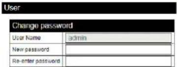
User Change password User Name admin New password Re-enter password

User
Update the username and password of the AT-HDVS-CAM-HDMI webGUI.
- Select Reset from the side menu.

ATLONA.
a PANOUIT company
Home
- Status
- Firmware
Device Settings
- System
■ Network
• Uber - Reset
isual Settings
• Picture
• Focus
• EXPOSURE
- Exposure
- Unknown Break-up
- Noise Reduction
- style
- OSD
• Video Out
Camera
• Control
- Logout
Factory Reset
Factory Reset - Sets the device back to the original factory settings.
Reboot
Reboot - Reboots the AT-HDVS-CAM-HDMI.
- Select Picture from the side menu.

ATLONA
a PANOUIT company
Home
- Status
- Firmware
Device Settings
- System
- Network
- User
- Reset
Visual Settings
- Picture
• Focus
• Exposure - Noise Reduction
• Style
• QSD - Video Out
Camera
• Control
- Logout
Picture Settings
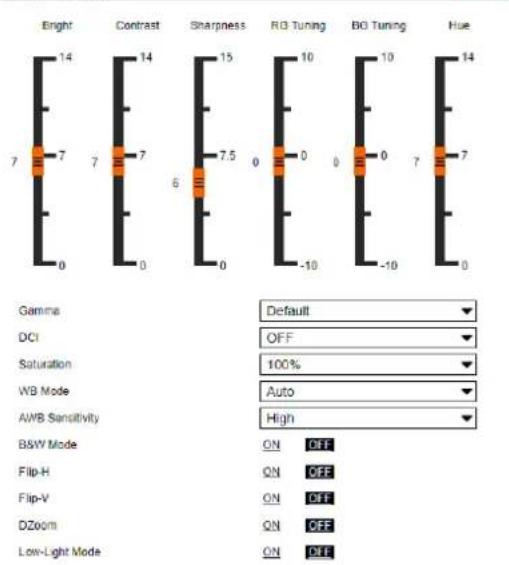
bar
| Effect Type | Value | | ----------------- | ----- | | Bright | 14 | | Contrast | 14 | | Sharpness | 15 | | RG Tuning | 10 | | BG Tuning | 10 | | Hue | 14 | | Gamma | Default | | DCI | OFF | | Saturation | 100% | | WB Mode | Auto | | AWB Sensitivity | High | | BSW Mode | ON | | Flip-H | ON | | Flip-V | ON | | DZoom | ON | | Low-Light Mode | ON |Picture Settings
Brightness - Set to a value between 0 and 14. Default is 6.
Contrast - Set to a value between 0 and 14. Default is 8.
Sharpness - Set to a value between 0 and 15. Default is 7.
Gamma - Set the gamma value of the camera. Values are default, 0.45, 0.50, 0.52, and 0.55.
DCI (Dynamic Contrast Improvement) - Set to a value between 1 and 8 or OFF.
Saturation - Set to a value between 60% and 200%. Default is 80%.
WB Mode - Select between Auto, 3000K, 3500K, 4000K, 4500K, 5000K, 5500K, 6000K, 6500K, 7000K, Manual, and OnePush.
AWB Sensitivity - Select between low, middle, and high.
B & W Mode - Toggle color between black and white (ON) and color (OFF). Default is off.
Flip-H - Flip the picture horizontally. Default is off.
Flip-V - Flip the picture vertically. Default is off.
DZoom - Dynamic Zoom. Toggle between ON and OFF. Default is off.
Low-Light Mode - Toggle between ON and OFF. Default is off.
- Select Focus from the side menu.

ATLONA
a PANQUIT company
Home
- Status
- Filmware
Device Settings
- System
• Network
• Linos
- 2019
Visual Settings
• Picture
• Focus
- 采用安全控制
Exposure
- Noise Reduction
- Style
• OSD
- Video Out
Camera
• Control
- Logout

text_image
Focus Settings Auto Auto Focus Zone All Auto Focus Sensitivity LowFocus Settings
Focus Mode - Switch between Auto, Manual, or OnePush.
Auto Focus Zone - Switch the zone between Top, Center, Bottom, and All.
Auto Focus Sensitivity - Switch between High, Middle, and Low.
- Select Exposure from the side menu.

ATLONA
a PANOUIT company
Home
- Status
- Filmware
Device Settings
- System
- Network
• User
• Reset
Visual Settings
• Picture
• Focus
- Exposure
- Noise Reduction
• Style
• OSN
• Video Out
Camera
• Control
- Logout
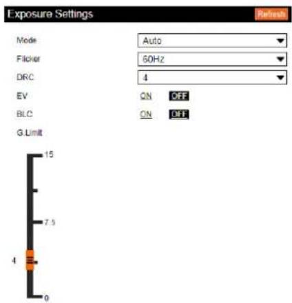
text_image
Exposure Settings Mode Auto Flicker 60Hz DRC 4 EV ON OFF BLC ON OFF G.Limit 15 7.5 4 0Exposure Settings
Mode - Switch between Auto, Manual, SAE, AAE, and Bright.
Flicker - Switch between OFF, 50Hz, and 60Hz.
DRC (Dynamic Range) - Set to a value between 1 and 8, or OFF.
EV (Exposure Compensation) - Toggle EV on and off.
BLC (Backlight Compensation) - Toggle backlight compensation on and off.
G.Limit (Gain Limit) - Set to a value between 0 and 15. Default is 3.
- Select Noise Reduction from the side menu.

ATLONA
a PANOUIT company
Home
- Status
- Firmware
Device Settings
- System
• Network - User
- Reset
Visual Settings
• Picture
• FOCUS
- Exposure
- Noise Reduction
• Style
- OSD
• Video Out
Camera
• Control
- Logout
Noise Reduction Settings
NR-2D Reduction
NR-3D Reduction
Dynamic Hot Pixel

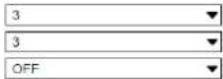
Noise Reduction Settings
NR-2D Reduction - Set to a value between OFF, 1 and 7, or Auto.
NR-3D Reduction - Set to a value between OFF, 1 and 8.
Dynamic Hot Pixel - Set to a value between 1 and 5, or OFF.
- Select Style from the side menu.

ATLONA
a PANOUIT company
Home
- Status
- Firmware
Device Settings
- System
• Network
- User
- Reset
Visual Settings
• Picture
• FOCUS
- Exposure
- Noise Reduction
- Style
• OSD
• Video Out
Camera
• Control
- Logoul
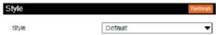
Style
Style - Set to a value between default, normal, clarity, bright, and soft.
- Select OSD from the side menu.

ATLONA
a PANOUIT company
Home
- Status
- Firmware
Device Settings
- System
- Network
• Linec
(3)
Visual Settings
• Picture
• Focus
- 三安办6155
- 10%
- Noise Reduction
• Style
- OSD
• Video Out
Camera
• Control
- Logout
OSD Settings
Show Title
Title Font Color
Scale Font with Resolution
Main Stream OSD Font Size
OSD Offset


OSD Settings
Show Title - Toggle the title on and off on the on screen display.
Title Font Color - Set the time's font color. Values are White, Black, Yellow, Red, and Blue.
Scale Font with Resolution - Toggle the font scaling on and off.
Main Stream OSD Font Size - Set the font size between 8 and 200.
OSD Offset - Use the buttons to position the OSD information on the screen.
- Select Video Out from the side menu.

ATLONA
a PANOUIT company
Home
- Status
- Firmware
Device Settings
- System
- Network
• Linear
(34)
Visual Settings
• Picture
• Focus
- 2016.01.05
- 2019
- Noise Reduction
• Style
- OSD
• Video Out
Camera
• Control
- Logout

text_image
Video Out Video Out Format: 1080P30 SaveVideo Out
Video Out Format - Set the output format. Values are 1080p60, 1080p50, 1080p30, 1080p25, 1080i60, 1080i50, 720p60, 720p50, 1080p59.94, 1080i59.94, 720p59.94, and 1080p29.97.
Save - Click to save changes.
- Select Control from the side menu.

ATLONA
a PANOUIT company
Home
- Status
- Firmware
Device Settings
• System
• Network
• User
• Here
Visual Settings
• Picture
• Focus
Exposure
• Main Production
- 下载/边码
• Style
• OSD
• Video Out
Camera
- Control
- Logout
Camera Control
Pan-Tilt-Zoom - Use the buttons to adjust the camera's view and position.
Focus Mode - Switch between Auto, Manual, and OnePush. Use the buttons to adjust the focus.
Preset - Set the current position settings to a preset and save.
Video buttons - Adjust video settings with these buttons.
IR Remote and OSD
IR Remote Control
The AT-HDVS-CAM-HDMI comes with an IR remote control for full control of the camera and use of the OSD menu.

text_image
SET CAMERA SELECT 1 2 3 4 1 2 3 4 5 6 7 8 9 * 8 # + AUTO + FOCUSZOOM MANUAL SET PRESET CLEAR PRESET HOME BLC ON/OFF MENU F1 F2 F3 F4IR Remote
Power - Toggle the camera on and off with the power button. Press and hold for 3 seconds to place the camera into standby mode.
Number Buttons - Use in the selection or creation of camera presets.
Focus - Adjust the focus of the camera using the + and - buttons.
Auto - Switch the camera focus mode to auto.
Manual - Switch the camera focus mode to manual.
Zoom - Zoom in (+) or out (-) using these buttons.
Set Preset - Set the camera into position then press the Set Preset button followed by a number key (0-9) to set that position to a preset.
Clear Preset - Press clear preset followed by a number key to erase the preset set to that number.
Arrow Buttons - Use the arrow buttons to adjust the camera position or navigate within the OSD menu.
Home Buttons - Returns the camera to the middle position.
BLC ON/OFF - Toggle the back light on and off.
Menu - Use to pull up the OSD menu.
OSD
The OSD will display after pressing the MENU button.
| OSD | |||||
| Language English Setup Protocol | Chinese Auto Visca PELCO-D PELCO-P (Options) | ||||
| Visca Address 1 1 | |||||
| Visca Address Off Off | |||||
| PELCO-P Address | 1 | 1 | |||
| PELCO-D Address | 1 | 1 | |||
| Baudrate | 9600 | 9600 | 9600 | 9600, | |
| OSD Cont. | ||||||||
| Camera Exposure Mode Auto Bright AAE SAE Manual | ||||||||
| Bright 7 0 | ||||||||
| IRIS F1.8 | F1.8 | 4, | F2.8, F3.4, F4.0,F4.8, F5.6, F6.8,F8.0, F9.6, F11,Close | |||||
| Shutter 1/100 1/100 | 0, | 1/60, 1/90, 1/100,1/120, 1/180,1/250, 1/325,1/500, 1/1000,1/2000, 1/3000,1/4000, 1/6000,1/10000 | ||||||
| EV | ON | ON, OFF | ||||||
| EV Level | 0 | -7 to 7 | ||||||
| BLC | OFF | ON, OFF | ||||||
| Flicker | 50Hz | 50Hz | 50Hz | OFF, 50Hz, 60Hz | ||||
| G. Limit | 4 | 4 | 4 | 0 to 15 | ||||
| DRC | 4 | 4 | 4 | 4 | Close, 1 to 8 | |||
| Color | WB Mode | Auto | Onepush | Manual | 7000K | 6500K | 5500K, 5000K,4500K, 4000K,3500K, 3000K | |
| RG Tuning | 0 | RG145 | -10 to 10 | |||||
| BG Tuning | 0 | BG56 | -10 to 10 | |||||
| Saturation | 100% | 100% | 100% | 100% | 100% | 60, 100, 110, 120,200 | ||
| Hue | 7 | 7 | 7 | 7 | 7 | 0 to 14 | ||
| AWB Sens | High | High, Middle, Low | ||||||
| Image | Brightness | 6 | 0 to 14 | |||||
| Contrast | 8 | 0 to 14 | ||||||
| Sharpness | 6 | 0 to 15 | ||||||
| Flip-H | OFF | OFF, ON | ||||||
| Flip-V | OFF | OFF, ON | ||||||
| B&W Mode | Color | Color, B&W | ||||||
| Gamma | 0.45 | Default, 0.45, 0.50, 0.55, 0.63 | ||||||
| DCI | 2 | Close, 1 to 8 | ||||||
| Image Quality | 0 | 0 to 5 | ||||||
| Focus | Focus Mode | Auto | Auto, Onepush, Manual | |||||
| AF-Zone | Center | Center, Top, All, Bottom | ||||||
| AF-Sensitivity | Low | Low, High, Middle | ||||||
| Noise Reduction | NR-2D | 2 | OFF, Auto, 1 to 7 | |||||
| NR-3D | 4 | OFF, 1 to 8 | ||||||
| Dynamic Hot Pixel | OFF | OFF, 1 to 5 | ||||||
| Style | Clarity | Clarity, Normal, Default, Soft, Bright | ||||||
| OSD Cont. | |||
| P/T/Z Speed By Zoom ON ON, OFF | |||
| Zoom Speed 8 1 to 8 | |||
| Acc Curve Slow Slow, Fast | |||
| Version | MCU Version | X.X.X | 20YY-MM-DD |
| Camera Version | X.X.X | 20YY-MM-DD | |
| AF Version | X.X.X | 20YY-MM-DD | |
| Ethernet | IP Address | XXX.XXX.XXX.XXX | e.g. 10.20.20.233 |
| Subnet Mask | XXX.XXX.XXX.XXX | e.g. 255.255.255.0 | |
| Gateway | XXX.XXX.XXX.XXX | e.g. 10.20.20.1 | |
| Restore Default | Restore Default? | NO, YES - Restore Default Now... | |
Remote Functions
The included IR Remote Control provides a set of functions which can be used to change the behavior of the AT-HDVS-CAM-HDMI. Each function is invoked by sequentially pressing the following series of keys on the keypad.
| Function Keystrokes | |
| Clear all presets [#] + [#] + [#] | |
| Flip video horizontally and vertically [*] + [#] + [9] | |
| Reset username, password, and IP address [*] + [#] + [MANUAL] | |
| Switch video format to 1080p60 [#] + [#] + [0] | |
| Switch video format to 1080p50 [#] + [#] + [1] | |
| Switch video format to 1080i60 [#] + [#] + [2] | |
| Switch video format to 1080i50 [#] + [#] + [3] | |
| Switch video format to 720p60 [#] + [#] + [4] | |
| Switch video format to 720p50 [#] + [#] + [5] | |
| Switch video format to 1080p30 [#] + [#] + [6] | |
| Switch video format to 1080p25 [#] + [#] + [7] | |
| Switch video format to 720p30 [#] + [#] + [8] | |
| Switch video format to 720p25 [#] + [#] + [9] | |
Appendix
Specifications
| Video | |
| HD/SD/VESA(all resolutions are @30/25/20/15/10/5Hz) | 1080p, 720p, 1024x768, 1024x576, 960x540, 800x600, 640x360, 720x576, 640x480, 352x288, 320x240, 320x180, 176x144 |
| Viewing Angle 6.43° (telephoto), 60.9° (wide-angle) | |
| Effective Pixels 2.07 million | |
| Total Pixels 2.10 million | |
| Focus Settings Auto / Manual | |
| F-Stop f/1.6 - f/3.0 | |
| Focal Length 4.7 mm - 47 mm | |
| Zoom Ratio 10:1 | |
| Exposure Compensation -7 ~ +7 | |
| Minimum Illumination 0.5 lux @ f/1.8 with Automatic Gain Contol ON | |
| Signal-to-Noise Ratio (SNR) > 55 dB | |
| Control Protocol VISCA/Pelco-D/Pelco-P | |
| Pan Rotation +170° to -170° | |
| Tilt Rotation -30° to +90° | |
| Pan Control Speed 0.1 - 180° / sec | |
| Tilt Control Speed 0.1 - 80° / sec | |
| Temperature | Fahrenheit | Celsius |
| Operating | 14 to 122 | -10 to 50 |
| Storage | -14 to 140 | -10 to 60 |
| Operating Humidity (RH) | 20% to 80%, non-condensing | |
| Storage Humidity (RH) | 20% to 95%, non-condensing | |
| Power | ||
| Consumption | 12 W | |
| Supply Input: 110 - 220 V AC, 50/60 HzOutput: 12 V DC, 1 A | ||
| Dimensions Inches | Millimeters | |
| H x W x D | 6.59 x 5.90 x 5.90 | 167.5 x 150 x 150 |
| Weight | Pounds | Kilograms |
| Device | 3.08 | 1.4 |
| Certification | |
| Device | CE, FCC |