
DAV-7654 - Wi-Fi repeater DAVIS - Free user manual and instructions
Find the device manual for free DAV-7654 DAVIS in PDF.

| Brand | Davis Instruments |
| Model | DAV-7654 (Long Range Repeater) |
| Product Type | Long Range Wireless Repeater for Vantage Pro2 and Vantage Vue weather stations |
| Dimensions | 6.25 x 2.25 x 7.88 in (159 x 57 x 200 mm) |
| Weight | 1.188 lb (0.539 kg) |
| Housing Material | UV-resistant PVC plastic |
| Power Supply | Solar panel (0.5 Watts) or AC power adapter (optional) |
| Battery Type | CR 123A 3-volt lithium battery |
| Battery Life (with solar) | Over 2 years typical |
| Current Draw (average) | 1.5 mA at 4-6 VDC |
| Operating Temperature | -40 to 150°F (-40 to 65°C) |
| Frequency Band (North America) | 902-928 MHz FHSS |
| Frequency Band (EU) | 868.0-868.6 MHz FHSS |
| Max Range (line of sight) | Up to 2 miles (3 km) depending on antenna pair |
| Antenna Compatibility | Omnidirectional (#7656, 5 dBi) or Yagi (#7660, 11 dBi) |
| ID Codes Available | 8 |
| Transmit Interval | 2.5625 - 3.0000 seconds depending on ID |
| Compatible Devices | Vantage Pro2, Vantage Pro2 Plus, Vantage Vue, Envoy8X, Weather Envoy, Vantage Connect |
| FCC ID | IRDWW765Y |
| IC Number | 3788A-765Y |
Frequently Asked Questions - DAV-7654 DAVIS
User questions about DAV-7654 DAVIS
0 question about this device. Answer the ones you know or ask your own.
Ask a new question about this device
Download the instructions for your Wi-Fi repeater in PDF format for free! Find your manual DAV-7654 - DAVIS and take your electronic device back in hand. On this page are published all the documents necessary for the use of your device. DAV-7654 by DAVIS.
USER MANUAL DAV-7654 DAVIS
Installation Addendum
Long Range Repeater
For Vantage Pro2, Vantage Pro2 Plus, Vantage Vue, Envoy8X, Weather Envoy, and Vantage Connect
Product Number 7654 for use with antennas 7656 & 7660
FCC Part 15 Class B Registration Warning
This equipment has been tested and found to comply with the limits for a Class B digital device, pursuant to Part 15 of the FCC Rules. These limits are designed to provide reasonable protection against harmful interference in a residential installation. This equipment generates, uses, and can radiate radio frequency energy and, if not installed and used in accordance with the instructions, may cause harmful interference to radio communications.
However, there is no guarantee that interference will not occur in a particular installation. If this equipment does cause harmful interference to radio or television reception, which can be determined by turning the equipment on and off, the user is encouraged to try to correct the interference by one or more of the following measures:
- Reorient or relocate the receiving antenna.
- Increase the separation between the equipment and receiver.
- Connect the equipment into an outlet on a circuit different from that to which the receiver is connected.
- Consult the dealer or an experienced radio/TV technician for help.
Changes or modification not expressly approved in writing by Davis Instruments may void the warranty and void the user's authority to operate this equipment.
FCC ID: IRDWW765Y
IC: 3788A-765Y
EC EMC Compliance: This product (model 7654OV) complies with the essential protection requirements of the Radio Equipment Directive 2014/53/EU. The complete Declaration of Conformity is on our website at https://www.davisnet.com/legal. RoHS Compliant.
This device has been designed to operate with an antenna having a maximum gain of 11 dBi. Antennas having a higher gain are strictly prohibited per regulations of Industry Canada. The required antenna impedance is 50 ohms. To reduce potential radio interference to other users, the antenna type and its gain should be chosen so that the equivalent isotropically radiated power (EIRP) is not more than that required for successful communication.
The Long Range Repeater can be used with any wireless Vantage Pro2™ or Vantage Vue transmitting station to re-transmit to a Vantage Pro2 compatible receiver (Vantage Pro2 or Vantage Vue console; Vantage Connect, Weather Envoy or Envoy8X, or a standard Wireless Repeater). The Long Range Repeater works in much the same way as the Vantage Pro2 wireless repeater, but extends the distance between a repeater and a receiver by up to 10 times that of the standard Vantage Pro2 wireless repeater (# 7627).
Long Range Repeater Addendum Overview
This addendum provides additional information specific to the installation and use of the Long Range Repeaters and is intended to be used in conjunction with the Wireless Repeater Installation Manual. The table below shows the location of the information required to install and maintain your Long Range Repeaters:
| Section/Procedure | This Addendum | Wireless Repeater Manual |
| Components and Hardware X | ||
| Repeater Board Contents X X | ||
| Additional Antenna Components and Hardware X | ||
| Tools for Setup X | ||
| Additional Tools for Setup X | ||
| Wireless Repeater Introduction X | ||
| Repeater Configurations/Architecture X | ||
| Long Range Repeater Antenna Configuration X | ||
| Applying Power X | ||
| Single Repeater Installation X | ||
| Advanced Repeater Installation X | ||
| Mounting Long Range Wireless Repeater and Antennas X | ||
| Connecting External Antennas to the Repeater X | ||
| Console and WeatherLink Configuration X | ||
| Repeater Communication Troubleshooting | X | |
| Long Range Repeater Specification | X |
Repeater Board Contents
The board contained within the repeater enclosure has the following contents:
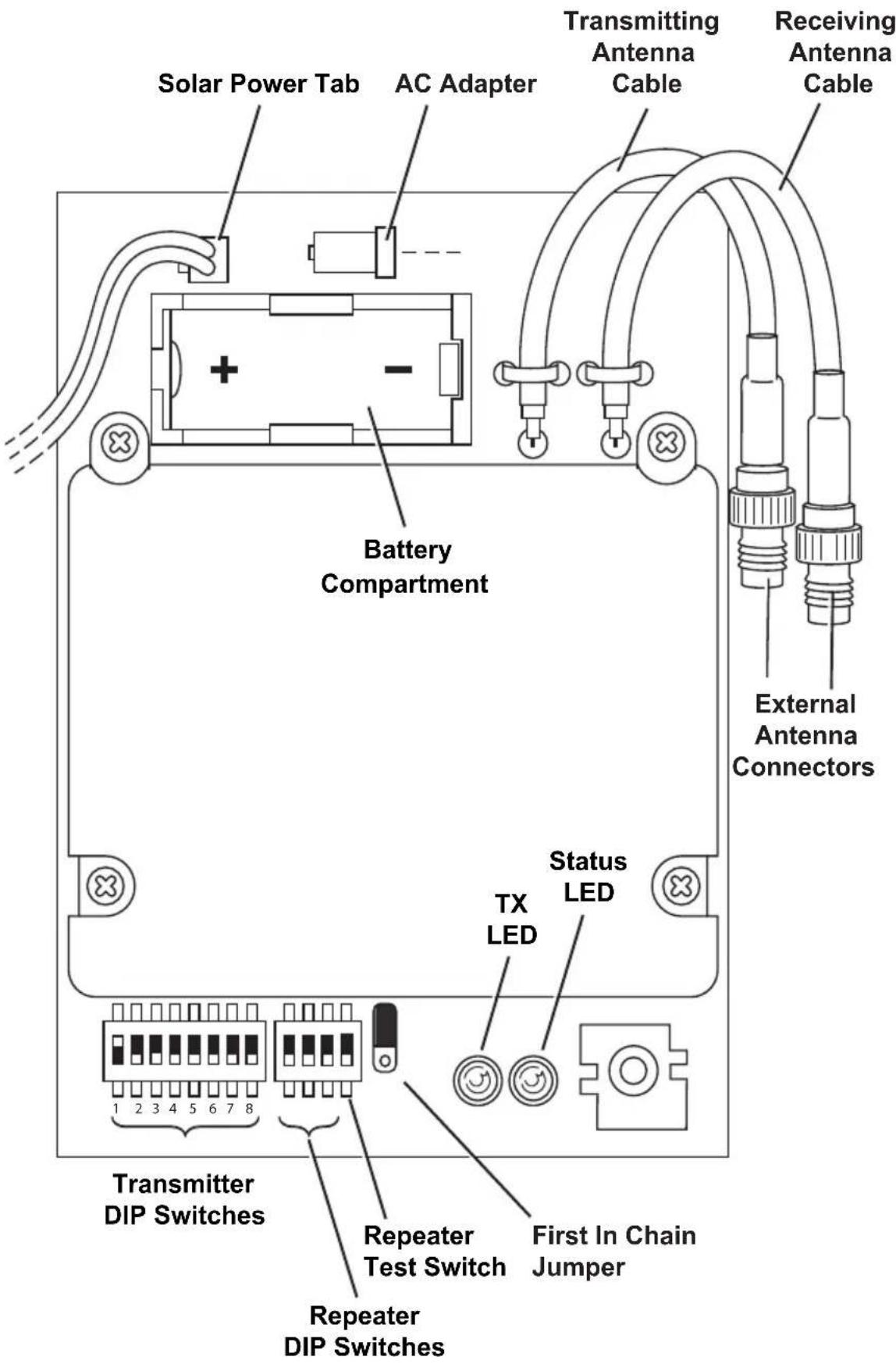
The components unique to the Long Range Repeater board are:
• Transmitting Antenna Cable — Connects the repeater to the external transmitting antenna. • Receiving Antenna Cable — Connects the repeater to the external antenna receiving a station or repeater signal.
Additional Tools for Setup
In addition to the tools required for standard wireless repeater installation, the following additional tool is required to set up and install the long range repeater:
- Socket wrench with 1/2" socket
Long Range Repeater Hardware
Each long range repeater requires TWO external antennas: one for receiving from a transmitting station or wireless repeater, and one for transmitting the data to another repeater or receiver. The two external antenna choices are:
• Omni-directional antenna, product number 7656 • Yagi (directional) antenna, product number 7660
You must purchase external antennas appropriate to your network architecture requirements.
| Note: | Davis Instruments sells FCC Type approved antennas for the long range repeater. These antennas are available for US customers only. US customer MUST use Davis antennas. Overseas customers are responsible for procuring their own long range antennas for use with the long range wireless repeater that comply with local regulations. See “Specifications” on page 13 for more information. |
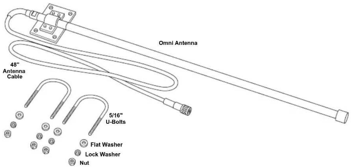
Omni Antenna
The omni-direction antenna includes the omni-directional antenna and mounting hardware:
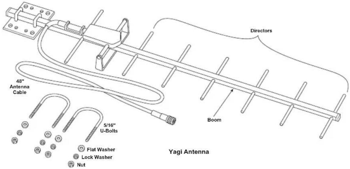
Yagi (Directional) Antenna
The Yagi antenna includes the directional antenna and mounting hardware:
External Antenna Types
The Omni and Yagi antennas transmit and receive with two different radiation patterns.
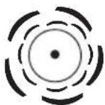
External Antenna Radiation Patterns (Top View)
Omni-Direction Antenna (radiation pattern 360°)
Yagi Antenna (radiation pattern +/- 25°)
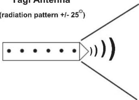
The Davis long-range omni antenna transmits and receives data in a radiation pattern of 360°, the same radiation pattern as a standard Vantage Pro2 dipole antenna. The Yagi antenna transmits and receives data packets in a 50° beam from the front of the Yagi antenna. The antenna is limited in the angle and direction it can transmit and receive packets, but it increases the distance between transmitter, repeater, and receiver proportionally.
All wireless Davis Instruments stations and standard wireless repeaters come equipped with standard dipole antennas that have an omni-directional radiation pattern.
It is important to remember that each long-range repeater will have two antennas. You can think of one as the “microphone” to receive data, and the other as the “speaker” to transmit data. The two antennas do not have to be the same. It is important to keep in mind which is the “microphone” and which is the “speaker.”
To determine which antenna or antenna combination is needed for your network:
- The Yagi antenna is the most powerful and will give the longest range. However, you can only use it if the data is being received from or transmitted to stations within a 50° angle of the antenna.
- You should use the omni antenna if receiving or transmitting in multiple directions.
Note: The best Yagi antenna performance is always achieved by pointing the antenna directly at the antenna at the other end of the link.
Antenna Ranges
Each antenna type in a repeater network varies in the distances it can receive and transmit data. For instance, the dipole antenna on an integrated sensor suite transmitting to a dipole antenna on a console is limited to 1000'. A dipole transmitting to an omni antenna lengthens the distance to 1580' because the omni has a better "microphone." A Yagi antenna has an even stronger "microphone" and can "hear" a dipole antenna up to 3,160 feet. The table below shows the total distances of each antenna (receiver and transmitter) combination. (Examples of dipole antennas are Vantage Pro2 or Vantage Vue integrated sensor suites and consoles, Envoy, Vantage Connect, standard wireless repeaters, Leaf Wetness and Soil Moisture stations, Wireless Temperature Stations, etc.).
| Antenna Pair | Maximum Transmission DistanceUnder optimal conditions | |
| Dipole - Dipole | 1000 feet300 meters | 0.2 miles0.3 km |
| Dipole - Omni | 1,580 feet480 meters | 0.3 miles0.5 km |
| Dipole - Yagi | 3,160 feet960 meters | 0.6 miles1 km |
| Omni - Omni | 2,500 feet760 meters | 0.5 miles0.8 km |
| Omni - Yagi | 5,000 feet1542 meters | 1 mile1.5 km |
| Yagi - Yagi | 10,0003,000 meters | 2 miles3 km |
Antenna Configurations
When designing your system, consider the need for increased range as well as the need for directionality. Keep in mind which antenna on your long-range repeater is the receiving antenna and which is the transmitting antenna. Below is an example of a system that uses a standard repeater and a long-range repeater with an omni antenna receiving and a Yagi antenna transmitting.
![graph TD A["Transmitter Vantage Pro2 Integrated Sensor Suite"] -->|Dipole to Dipole 1,000 feet| B["Standard Repeater"] B -->|Dipole to Omni 1,580 feet| C["Long-Range Repeater with 1 omni antenna (rx) 1 Yagi antenna (tx)"] C -->|Yagi to Dipole 3,160 feet| D["Receiver Vantage Pro2 Console"] A --> E["T…](/content/2026/06/1147631/images/4aba675d99ddde3717d102a03e118e2325027df2536269e4dc9cac1478d9af9e.jpg)
Mounting the Repeater and External Antennas
The antenna configuration and long-range repeater can be mounted on a pole. Use the provided U-bolts for the wireless repeater and the U-bolts provided for each antenna type to install them all to a pole.
Note: To accommodate your antenna configuration (omni and Yagi or Yagi and Yagi), mount the antennas first before mounting the wireless repeater enclosure.
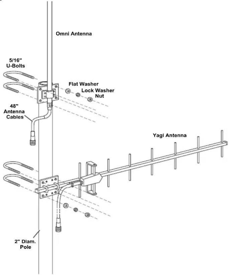
Omni and Yagi Antenna Combination Assembly
The omni and Yagi combination assembly should be performed from the bottom antenna (Yagi) up to the top antenna (Omni) so that the omni antenna can be installed flush to the top of the pole.
- Place the Yagi on the pole.
- Place a U-bolt around the pole and through the two holes at the top and of the antenna plate.
- Place a flat washer, a lock washer and a hex nut on each of the bolt ends.
- Using an adjustable wrench or 1/2" wrench, tighten the nuts.
- Place the second U-bolt around the pole and through the two holes at the bottom of the shelter.
- Put a flat washer, a lock washer, and a hex nut on each bolt end, and tighten the hex nuts so that the Yagi remains in place, but can still be adjusted.
- If the Yagi antenna is the receiving antenna, rotate it so that it points in the direction of the transmitting station (such as the ISS or a repeater). If it is the receiving antenna, rotate it so that it points at the receiver (such as a repeater or console). The antenna should also be installed so that the directors, the smaller cross bars on the boom, are parallel with the omni antenna.
- Tighten the hex nuts so that the Yagi is firmly attached.
- Place the omni antenna a distance above the Yagi antenna, providing space between the mounted antennas.
Ideally, omni antenna should be mounted flush with the very top of the pole, so that the pole does not interfere with the antenna's communication.
- While holding the omni antenna against the pole, place a U-bolt around the pole and through the two holes at the top and of the antenna plate.
- Place a flat washer, a lock washer and a hex nut on each of the bolt ends.
- Using an adjustable wrench or 1/2" wrench, tighten the nuts.
- Place the second U-bolt around the pole and through the two holes at the bottom of the shelter.
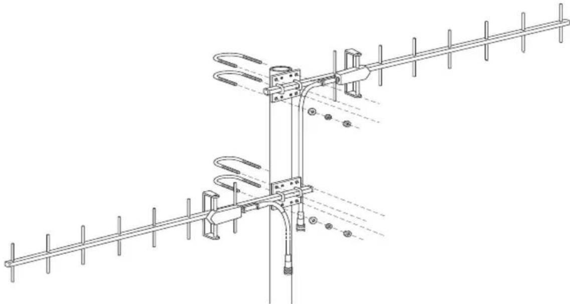
Two Yagi Antenna Combination Assembly
The Yagi and Yagi assembly should be performed from the bottom antenna (Yagi) up to the top antenna (Yagi) so that the Yagi antenna can be installed flush to the top of the pole.
Note: Be mindful of which antenna is to be the receiving antenna and which is to be the transmitting antenna.
- Place the Yagi on the pole in the general vicinity of the desired station/repeater/receiver.
- Place a U-bolt around the pole and through the two holes at the top and of the antenna plate.
- Place a flat washer, a lock washer and a hex nut on each of the bolt ends.
- Using an adjustable wrench or 1/2" wrench, tighten the nuts.
- Place the second U-bolt around the pole and through the two holes at the bottom of the shelter.
- Put a flat washer, a lock washer, and a hex nut on each bolt end, and tighten the hex nuts so that the Yagi remains in place, but can still be adjusted.
- If the first Yagi antenna is the receiving antenna, rotate it so that it points in the direction of the transmitting station (such as the ISS or a repeater). If it is the transmitting antenna, rotate it so that it points at the receiver (such as a repeater or console).
- Tighten the hex nuts so that the Yagi is firmly attached.
- Rotate the second Yagi so that it points to the desired transmitter/repeater/receiver.
- While holding the Yagi antenna in the correct alignment against the pole, place a U-bolt around the pole and through the two holes at the top of the antenna plate.
- Place a flat washer, a lock washer, and a hex nut on each of the bolt ends.
- Using an adjustable wrench or a 1/2" wrench, tighten the nuts.
- Place the second U-bolt around the pole and through the two holes at the bottom of the shelter.
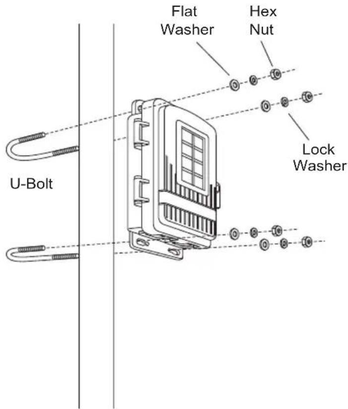
Installing a Repeater on a Pole
Refer to the following illustrations to install the repeater and antennas on a pole:
- Place the repeater enclosure on the pole somewhere below the antennas that makes it easy for the antenna cables to be routed around. It should be below the second antenna.
- Mount a repeater enclosure so that the solar panel receives the maximum amount of sunshine available at that location.
- While holding the shelter against the pole close to the bottom, place a U-bolt around the pole and through the two holes at the top of the shelter.
- Place a flat washer, a lock washer, and a hex nut on each of the bolt ends.
- Using an adjustable wrench or 7/16" wrench, tighten the nuts.
- Place the second U-bolt around the pole and through the two holes at the bottom of the shelter.
- Put a flat washer, a lock washer, and a hex nut on each bolt end, and tighten the hex nuts.
Connecting External Antennas to the Repeater
Tip:
It's important to be mindful of which antenna you have chosen to be the receiving antenna and which to be the transmitting antenna.
Once the repeater, and both external antennas have been attached to a pole and positioned, the antennas should be attached to the respective antenna cables in the wireless repeater enclosure. To do this:
- Thread each antenna cable into the individual black cable grommets at the bottom of the shelter to provide weather-resistant entrances for cables. Make sure that there is one antenna cable per grommet.
For identification purposes, the transmitting antenna cable should be threaded through the grommet on the left side and the receiving cable on the right side to align with the antenna cable connectors on the repeater board.
- Unscrew the cable clamps and thread each antenna cable through.
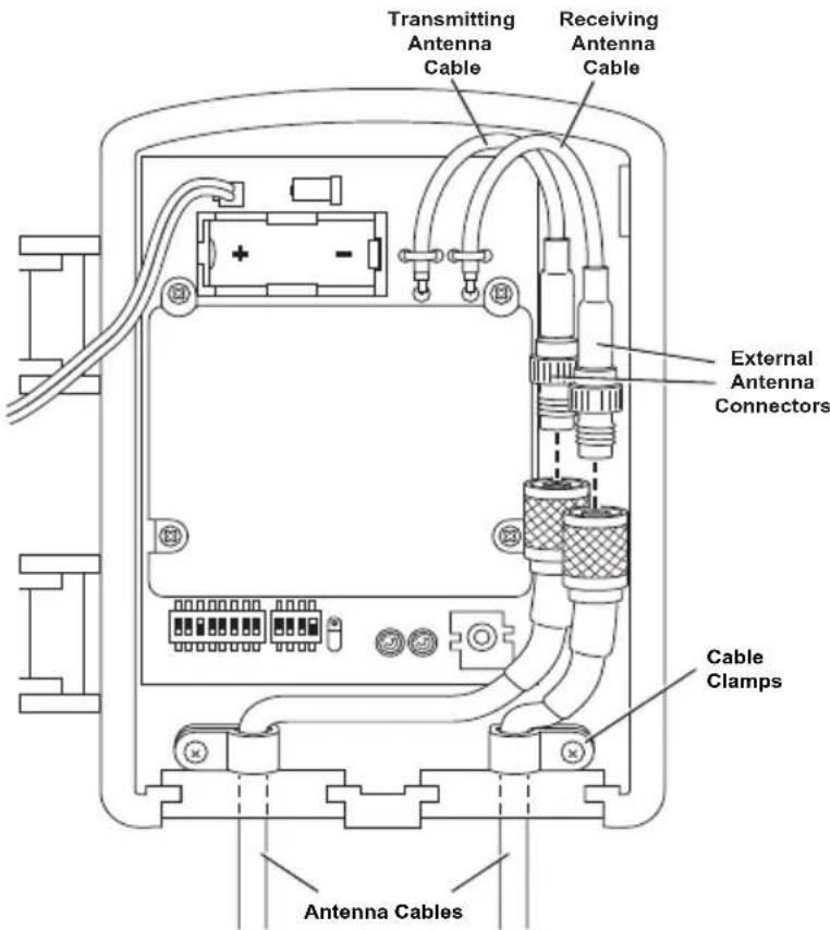
- Connect the transmitting antenna cable to the transmitting repeater connector.
- Connect the receiving antenna cable to the receiving repeater connector.
- Once all the antennas are mounted and connected to the repeater, test communication.
Specifications
Complete specifications for all of the Vantage Pro2 weather products as well as the wireless repeater are available in the Weather Support section of our website:
http://www.davisnet.com/support/weather/
General
Operating Temperature....-40 to 150° Fahrenheit (-40 to 65° Celsius)
Non-Operating Temperature ..... -40 to 150° Fahrenheit (-40 to 65° Celsius)
Current Draw 1.5 mA at 4-6 VDC (average draw when not in Test Mode and receiving from one transmitter)
Batteries CR 123A 3-volt lithium battery
Battery Life Estimates (with no solar or AC power input):
| # of IDs* | Estimated Life Expectancy (Months) |
| 1 | 4 |
| 4 | 1.5 |
| 8 | < |
1
*Both received directly by the repeater and those IDs repeated from the previous repeater in a chain.
Note: Battery life in excess of two years is expected with normal solar input.
Solar Panel 0.5 Watts
Alternate Power .... AC power adapter
Housing Material..... UV-resistant PVC plastic
Dimensions....6.25" x 2.25" x 7.88" (159 mm x 57 mm x 200 mm)
Weight. 1.188 lb. (.539 kg)
Transmit Interval
Repeater Transmit Interval .....2.5625 - 3.0000 seconds depending on ID
Wireless Communication: North America
Transmit/Receive Frequency
& Output Power: 902-928 MHz FHSS: FCC-certified low power, less than 8 mW, no license required
| Type Gain | |
| Omnidirectional Antenna (#7656) 5 dBi | |
| Yagi Antenna (#7660) 11 dBi | |
Range (Line of Sight) .... up to 2 miles (3 km) depending on antenna pair ID Codes Available .... 8
Wireless Communication (OV, models)
Transmit/Receive Frequency
& Output Power....868.0 - 868.6 MHz FHSS. CE-certified, less than 8 mW, no license required. Antenna gain cannot exceed 8 dBi maximum and no more than four transmitter IDs to comply with the EN 300 220 regulation.
ID Codes Available: 8
Range (Line of Sight) .... up to 1.5 km (5000'), assuming a pair of 8 dBi antennas.
Contacting Davis Technical Support
For questions about installing or operating your Long-Range Repeater, please contact Davis Technical Support. We'll be glad to help.
| (510) 732-7814 Monday - Friday. 7:00 A.M. to 5:30 P.M., Pacific Time. We are unable to accept collect calls. | |
| (510) 670-0589 Technical Support Fax. | |
| support@davisinstruments.com E-mail to Technical Support. | |
| info@davisinstruments.com General e-mail. | |
| www.davisinstrumentscom | Davis Instruments website. See the Weather Resources section for copies of manuals, product specifications, application notes, and information on software updates. Watch for FAQs and other updates. |
Vantage Pro2™ Long Range Wireless Repeater Addendum
Document Part Number: 07395.258 Rev D, 7/8/19
For Vantage Pro2 Long Range Wireless Repeater: 7654
Compatible with Vantage Pro2 Antennas: 7656, 7660
Vantage Pro2™, Vantage Vue®, Vantage Connect®, Weather Envoy™ and Envoy8X™ are trademarks of Davis Instruments Corp., Hayward, CA.
© Davis Instruments Corp. 2019. All rights reserved.
Davis Instruments Quality Management System is ISO 9001 certified.
Information in this document subject to change without notice.
- LONG RANGE REPEATER
- FCC PART 15 CLASS B REGISTRATION WARNING
- LONG RANGE REPEATER ADDENDUM OVERVIEW
- REPEATER BOARD CONTENTS
- ADDITIONAL TOOLS FOR SETUP
- LONG RANGE REPEATER HARDWARE
- OMNI ANTENNA
- YAGI (DIRECTIONAL) ANTENNA
- EXTERNAL ANTENNA TYPES
- ANTENNA RANGES
- ANTENNA CONFIGURATIONS
- MOUNTING THE REPEATER AND EXTERNAL ANTENNAS
- OMNI AND YAGI ANTENNA COMBINATION ASSEMBLY
- TWO YAGI ANTENNA COMBINATION ASSEMBLY
- INSTALLING A REPEATER ON A POLE
- CONNECTING EXTERNAL ANTENNAS TO THE REPEATER
- TIP
- SPECIFICATIONS
- GENERAL
- TRANSMIT INTERVAL
- WIRELESS COMMUNICATION: NORTH AMERICA
- WIRELESS COMMUNICATION (OV, MODELS)
- CONTACTING DAVIS TECHNICAL SUPPORT
- VANTAGE PRO2™ LONG RANGE WIRELESS REPEATER ADDENDUM
Brand : DAVIS
Model : DAV-7654
Category : Wi-Fi repeater