
32HDL51 - Television HITACHI - Free user manual and instructions
Find the device manual for free 32HDL51 HITACHI in PDF.


| Product Type | Television |
| Brand | Hitachi |
| Model | 32HDL51 |
| Screen Size | 32 inches (81 cm) |
| Resolution | 1366 x 768 pixels (HD Ready) |
| Aspect Ratio | 16:9 |
| Brightness | 350 cd/m² |
| Contrast Ratio | 1000:1 (typical) |
| Viewing Angle | 178° horizontal / 178° vertical |
| Refresh Rate | 60 Hz |
| Audio Power | 2 x 8W (RMS) |
| Power Consumption (Operational) | 55 W |
| Power Consumption (Standby) | <0.5 W |
| Power Supply | AC 100-240V, 50/60 Hz |
| Tuner | DVB-T/C (MPEG-4) |
| Connectivity | HDMI x2, USB x1, VGA x1, SCART x1, RF x1, Composite AV x1 |
| Features | Teletext, Sleep Timer, Child Lock, Auto Shut-off, Picture Modes |
| Cleaning | Wipe with a soft, dry cloth; do not use liquid cleaners |
| Safety Precautions | Do not expose to rain or moisture; ensure proper ventilation; use only specified accessories |
| Spare Parts Availability | Contact authorized Hitachi service centers |
| Repairability Index | 5.5 / 10 (estimated based on industry average) |
| Energy Class | A (typical for HD ready 32 inch) |
Frequently Asked Questions - 32HDL51 HITACHI
User questions about 32HDL51 HITACHI
0 question about this device. Answer the ones you know or ask your own.
Ask a new question about this device
Download the instructions for your Television in PDF format for free! Find your manual 32HDL51 - HITACHI and take your electronic device back in hand. On this page are published all the documents necessary for the use of your device. 32HDL51 by HITACHI.
USER MANUAL 32HDL51 HITACHI
AVC (Audio Video Control Center) & LCD Display Monitor
Operating Guide for 32HDL51
IMPORTANT SAFETY INSTRUCTIONS 2-3
FIRST TIME USE 4-26
THE REMOTE CONTROL 27-49
ON-SCREEN DISPLAY....50-77
USING THE RGB INPUT OF THE LCD TV 78-87
CARE OF YOUR HITACHI LCD TV & REMOTE CONTROL 88
RECEPTION PROBLEMS 89
USEFUL INFORMATION/INDEX 90-98
SAFETY POINTS YOU SHOULD KNOW ABOUT YOUR HITACHI LCD TELEVISION
Our reputation has been built on the quality, performance, and ease of service of HITACHI LCD televisions.
Safety is also foremost in our minds in the design of these units. To help you operate these products properly, this section illustrates safety tips which will be of benefit to you. Please read it carefully and apply the knowledge you obtain from it to the proper operation of your HITACHI LCD television.
Please fill out your warranty card and mail it to HITACHI. This will enable HITACHI to notify you promptly in the improbable event that a safety problem should be discovered in your product model.
Follow all warnings and instructions marked on this LCD television. LCD television consists of AVC center and display Monitor.

CAUTION: TO REDUCE THE RISK OF ELECTRIC SHOCK, DO NOT REMOVE COVER (OR BACK). NO USER SERVICEABLE PARTS INSIDE. REFER SERVICING TO QUALIFIED SERVICE PERSONNEL.
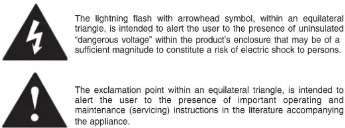
WARNING: • TO REDUCE THE RISK OF FIRE OR ELECTRIC SHOCK, DO NOT EXPOSE THIS APPARATUS TO RAIN OR MOISTURE. • THE LCD TELEVISION SHOULD NOT BE EXPOSED TO DRIPPING OR SPLASHING AND OBJECTS FILLED WITH LIQUIDS, SUCH AS VASES, SHOULD NOT BE PLACED ON THE TELEVISION.
NOTE: • There are no user serviceable parts inside the AVC center/display monitor. • Model and serial numbers are indicated on back side of the AVC center/display monitor.
CAUTION: Adjust only those controls that are covered in the instructions, as improper changes or modifications not expressly approved by HITACHI could void the user's authority to operate the television.
MODIFICATIONS: The FCC requires the user to be notified that any changes or modifications made to this device that are not expressly approved by Hitachi America, Ltd. Home Electronics Division may void the user's authority to operate the equipment.
POWER SOURCE
THIS TELEVISION IS DESIGNED TO OPERATE ON 120 VOLTS 60Hz, AC CURRENT. INSERT THE POWER CORD INTO A 120 VOLT 60Hz OUTLET.
TO PREVENT ELECTRIC SHOCK, DO NOT USE THE TELEVISION'S (POLARIZED) PLUG WITH AN EXTENSION CORD, RECEPTACLE, OR OTHER OUTLET UNLESS THE BLADES AND GROUND TERMINAL CAN BE FULLY INSERTED TO PREVENT BLADE EXPOSURE.
NEVER CONNECT THE TELEVISION TO 50Hz, DIRECT CURRENT, OR ANYTHING OTHER THAN THE SPECIFIED VOLTAGE.
NOTE: This television receiver will display television closed captioning, (cc or □), in accordance with paragraph 15.119 of the FCC rules.

CAUTION: Never remove the back cover of the AVC center/display monitor as this can expose you to very high voltages and other hazards. If the television does not operate properly, unplug the LCD television and call your authorized dealer or service center.
Read before operating equipment
Follow all warnings and instructions marked on this television.
- Read these instructions.
- Keep these instructions.
- Heed all warnings.
- Follow all instructions.
- Do not use this apparatus near water.
-
Clean only with a dry cloth.
-
Do not block any ventilation openings. Install in accordance with the manufacturer's instructions.
-
Do not install near any heat sources such as radiators, heat registers, stoves, or other apparatus (including amplifiers) that produce heat.
-
Do not defeat the safety purpose of the polarized or grounding-type plug. A polarized plug has two blades with one wider than the other. A grounding type plug has two blades and a third grounding prong. The wide blade or the third prong are provided for your safety. If the provided plug does not fit into your outlet, consult an electrician for replacement of the obsolete outlet.
-
Protect the power cord from being walked on or pinched particularly at plugs, convenience receptacles, and the point where they exit from the apparatus.
-
Only use the attachments/accessories specified by the manufacturer.
-
Use only with the cart, stand, tripod,

bracket, or table specified by the manufacturer, or sold with the apparatus. When a cart is used, use caution when moving the cart/apparatus combination to avoid injury from tip-over.
-
Unplug this apparatus during lightning storms or when unused for long periods of time.
-
Refer all servicing to qualified service personnel. Servicing is required when the apparatus has been damaged in any way, such as power-supply cord or plug is damaged, liquid has been spilled or objects have fallen into apparatus, the apparatus has been exposed to rain or moisture, does not operate normally, or has been dropped.
-
Televisions are designed to comply with the recommended safety standards for tilt and stability.
Do not apply excessive pulling force to the front, or top, of the cabinet which could cause the product to overturn resulting in product damage and/or personal injury. - Follow instructions for wall, shelf or ceiling mounting as recommended by the manufacturer.
- An outdoor antenna should not be located in the vicinity of overhead power lines or other electrical circuits.
- If an outside antenna is connected to the receiver be sure the antenna system is grounded so as to provide some protection against voltage surges and built up static charges. Section 810 of the National Electric Code, ANSI/NFPA No. 70-1984, provides information with respect to proper grounding for the mast and supporting structure, grounding of the lead-in wire to an antenna discharge unit, size of grounding connectors, location of antenna-discharge unit, connection to grounding electrodes and requirements for the grounding electrode.
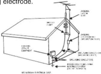
Note to the CATV system installer: This reminder is provided to call the CATV system installer's attention to Article 820-40 of the NEC that provides guidelines for proper grounding and, in particular, specifies that the cable ground shall be connected to the grounding system of the building, as close to the point of cable entry as practical.
Do not place any objects on the top of the television which may fall or cause a child to climb to retrieve the objects.
- This product contains lead and lamps that contains mercury. Dispose of this product and its lamps in accordance with applicable environmental laws. For lamp recycling and disposal information, go to www.lamprecycle.org. For product recycling and disposal information, contact your local government agency or the Electronic Industries Alliance at www.eiae.org (in the US) or the Electronic Product Stewardship Canada at www.epsc.ca (in Canada). For more information, call “1-800-HITACHI.”
PUBLIC VIEWING OF COPYRIGHTED MATERIAL
Public viewing of programs broadcast by TV stations and cable companies, as well as programs from other sources, may require prior authorization from the broadcaster or owner of the video program material.
- This digital television is capable of receiving analog basic, digital basic and digital premium cable television programming by direct connection to a cable system providing such programming. A CableCARD provided by your cable operator is required to view encrypted digital programming. Certain advanced and interactive digital cable services such as video-on-demand, a cable operator's enhanced program guide and data-enhanced television services may require the use of a set-top box. For more information call your local cable company.
- This product incorporates copyright protection technology that is protected by U.S. patents and other intellectual property rights. Use of this copyright protection technology must be authorized by Macrovision Corporation, and is intended for home and other limited consumer uses only unless otherwise authorized by Macrovision. Reverse engineering or disassembly is prohibited.
Check to make sure you have the following accessories before disposing of the packing material.
| REMOTE BATTERIES POWER CORD (2) CONTROL CONNECTION CABLE CABLE (2) | |||
| 2. | 3. 4. | 5. | |
| Subwoofer Cable 6. | Cleaning Cloth 7. | ||
| 1. | |||

CAUTION: 1. Ceiling mounting is not recommended. Mounting the panel on the ceiling does not provide adequate ventilation for the electronics or proper support for the front glass panel.
| 3. Power Cord: | 32" |
| LCD Monitor | EV01841 |
| AVC EV01841 |
- Remote Control Unit CLU-3841WL (P# HL02061) 6. Sub Woofer Cable (P# VZ11701). or CLU-3843WL (P# HL02063). 7. Cleaning Cloth (P# MS00931).
- Two "AA" size, 1.5V batteries (P# FQ00021).
- Monitor Connection Cable (P# EW07883).
- Two IR Mouse cables (P# EY01641).
REMOTE CONTROL BATTERY INSTALLATION AND REPLACEMENT
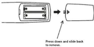
- Open the battery cover of the remote control by pushing the notched part of the cover with your fingers and pulling the cover off. BOTTOM VIEW
- Insert two new "AA" size batteries for the remote control. When replacing old batteries, push them towards the springs and lift them out.
- Match the batteries to the (+) and (-) marks in the battery compartment.
- Replace the cover.

CAUTION: Danger of explosion if battery is incorrectly replaced. Replace with the same or equivalent type.
BOTTOM VIEW (Remote Control)
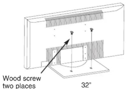
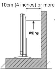
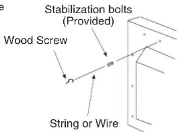
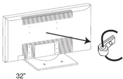
To take measures to prevent the LCD Display from tipping over and prevent possible injury it is important to mount the unit in a stable place.
Securing to a table-top
- Using wood screws (two) fasten the set to the clamping screw holes on the rear of the LCD Display stand as shown below.
- Using commercially available wood screws, secure the set firmly in position.
- Leave some space around the unit for proper operation of the power swivel stand.
Securing to a wall
- Keep the LCD Display monitor four inches away from the wall except those hung to a wall mount bracket.
- Secure the monitor to the wall as shown below.
NOTES: 1. Do not block the ventilation holes of the LCD Display monitor or the AVC center. Blocking the ventilation holes might cause fire or defect.
- The LCD television has two AC cords, one on the AVC center and the other on the LCD Display monitor. In case of an abnormal symptom, unplug both AC cords.
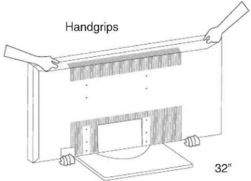
Caution when moving the main unit
As this product is heavy, whenever it is moved, two people are required to transport it safely. Whenever the unit is moved it should be lifted forward using the top and bottom frame on both sides of the 32" for stability, as shown below.
ANTENNA
Unless your LCD Television is connected to a cable TV system or to a centralized antenna system, a good outdoor color TV antenna is recommended for best performance. However, if you are located in an exceptionally good signal area that is free from interference and multiple image ghosts, an indoor antenna may be sufficient.
LOCATION
Select an area where sunlight or bright indoor illumination will not fall directly on the picture screen. Also, be sure that the location selected allows a free flow of air to and from the perforated back cover of the set.
To avoid cabinet warping, cabinet color changes, and increased chance of set failure, do not place the TV where temperatures can become excessively hot, for example, in direct sunlight or near a heating appliance, etc.
When installing your LCD TV against a wall, keep it at least 10 cm (4 inches) from the wall.
VIEWING
The major benefit of the HITACHI LCD Television is its large viewing screen. To see this large screen at its best, test various locations in the room to find the optimum spot for viewing.
The best picture is seen by sitting directly in front of the TV and about 8 to 18 feet from the screen.
During daylight hours, reflections from outside light may appear on the screen. If so, drapes or screens can be used to reduce the reflection or the TV can be located in a different section of the room.
If the TV's audio output will be connected to a Hi-Fi system's external speakers, the best audio performance will be obtained by placing the speakers equidistant from each side of the receiver cabinet and as close as possible to the height of the picture screen center. For best stereo separation, place the external speakers at least four feet from the side of the TV, place the surround speakers to the side or behind the viewing area. Differences in room sizes and acoustical environments will require some experimentation with speaker placement for best performance.
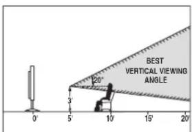
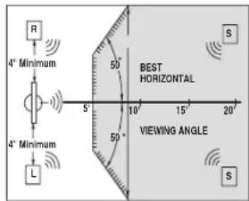
IMPORTANT NOTES
| No. | Items Notes | |
| 1 | Arching sound from LCD display monitor's panel. | A buzzing sound might be heard when the LCD display monitor is turned on in a very quiet room. This is due to the LCD panel drive circuit when it is functioning. This arching sound is normal and it is not a malfunction. |
| 2 | I nterference for infrared equipment. | Some infrared rays are emitted from the LCD display monitor's panel that might affect other infrared controlling equipment. |
| 3 | Picture Image (Spectrum) | When receiving still picture signals, (e.g. channel number indication or clock indication) for a while, you can see image-like when the picture varied. This is not a defect. |
| 4 | LCD Surface | The LCD panel is made from glass. Heavy shock on the front panel might damage it. |
| 5 | T r a n s p o | When the LCD monitor is transported horizontally, the glass panel has the possibility of being broken or increasing the picture defects. At the time of transportation, horizontal style is prohibited. More-over, please treat the LCD panel with great care because of a precision apparatus. Please instruct transporters so that it should be put into the packing box at the time of shipment.(There is a possibility that breakage of the panel or defects will increase.) Rough transportation might cause damage to the panel and pixel failure. |
| 6 | Granular spots | When a screen is seen at point-blank range, a random fine grain may be visible to a dark part. |
| 7 | Black dots and Bright Points | Black dots and Bright points may appear on the LCD screen. This is a structural property of the LCD panel and is not a defect. |
| 8 | Disturbance to video apparatus | If an apparatus (VCR, etc.) antenna line is arranged near the monitor, the image may shake, or disturbance may be received. |
| 9 | Lip Sync | There is some time lag between the picture and the sound. You can see lip motion that is delayed compared to the sound. |
| 10 | Caution on prolonged storage | Storing the LCD television for a period of more than 2 to 3 months without use might cause an unstable picture when the set is turned on. |
| 11 | Operating | Operating altitude: 800 to 1,114hPa (6,194ft to -2,484ft). Operating temperature: 41°F to 95°F. Avoid operating the LCD TV below 41°F LCD response speed may slow down when operating at these temperatures. This is a normal operating characteristic of the LCD monitor. |
| 12 | Storage | Storage Altitude: 300 to 1,114hPa (31,912ft to -2,484ft). Storage temperature: 5°F to 140°F. |
| 13 | Power ON or OFF | Frequent use of the Power ON or OFF might trigger the power protection circuit. If the TV does not turn ON, please wait a little before turning ON again. |
Most video/audio connections between components can be made with shielded video and audio cables that have phono connectors. For best performance, video cables should use 75-Ohm coaxial shielded wire. Cables can be purchased from most stores that sell audio/video products. Below are illustrations and names of common connectors. Before purchasing any cables, be sure of the output and input connector types required by the various components and the length of each cable.
natural_image
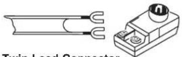
Technical line drawing of a twin lead connector with two copper leads (no text or symbols)300-Ohm Twin Lead Connector
This outdoor antenna cable must be connected to an antenna adapter (300-Ohm to 75-Ohm).

Phono Connector
Used on all standard video and audio cables which connect to inputs and outputs located on the rear jack panel and front control panel.
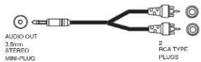
Stereo Cable (3.5 mm plug to 3.5 mm plug)
This cable is used to connect from external audio out to the audio input of the AVC Center (ex. RGB Input).

IR Mouse Cable (Provided)
Connect the IR Mouse to the IR output on your AVC center when A/V Network is used. You must place the IR mouse in front of the corresponding IR window of your cable box and VCR. This connection allows your TV to control your cable box and VCR.
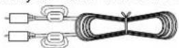
Subwoofer Cable (Provided)
This cable is used to connect an external audio component input to the subwoofer output of the Display Monitor.
natural_image
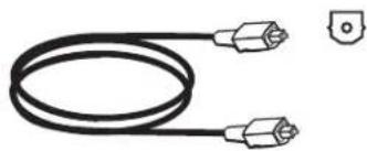
Simple line drawing of a coiled electrical plug with two connectors and a small terminal (no text or symbols)Optical Cable
This cable is used to connect to an audio amplifier with an Optical Audio In jack. Use this cable for the best sound quality.

HDMI Cable
This cable is used to connect your external devices such as Set-Top-Boxes or DVD players equipped with an HDMI output connection to the TV's HDMI input.
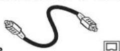
IEEE1394 Cable
This cable is used to connect your digital television to external digital devices. This cable will carry both the video and audio information.
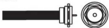
“F” Type 75-Ohm Coaxial Antenna Connector
For connecting RF signals (antenna or cable TV) to the antenna jack on the television.

S-Video (Super Video) Connector
This connector is used on camcorders, VCRs and laser-disc players with an S-Video feature in place of the standard video cable to produce a high quality picture.
natural_image
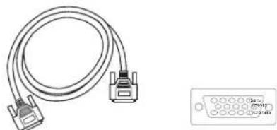
Illustration of a broadband cable with two connectors and a separate 3-pin connector (no text or symbols)D-SUB MINI 15-Pin Cable
This cable is used to connect a computer output to the ANALOG input located on the rear panel of the AVC Center. The resolution should be set correctly to display the signal on the LCD Television.
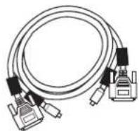
Monitor Connection Cable (Provided)
This cable is used to connect the Display Monitor to the AVC Center.
natural_image
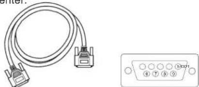
Pure electrical connector diagram showing a cable and a 53021 port (no text or symbols beyond basic labels)D-SUB MINI 9-Pin Cable
This cable is used to connect to the RS232C input located on the rear panel so you can control some of your TV functions from an external home control system.

USB Cable
This cable is used to connect your digital camera to the Photo Input in the front of the AVC.
VHF (75-Ohm) antenna/CATV (Cable TV)
When using a 75-Ohm coaxial cable system, connect the outdoor antenna or CATV coaxial cable to the ANT A (75-Ohm) terminal. If you have a second antenna, connect the coaxial cable to the ANT B terminal.
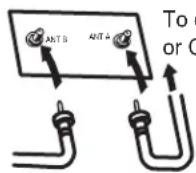
To second antenna
To outdoor antenna or CATV cable
VHF (300-Ohm) antenna/UHF antenna
When using a 300-Ohm twin lead from an outdoor antenna, connect the VHF or UHF antenna leads to screws of the VHF or UHF adapter. Plug the adapter into the antenna terminal on the TV.
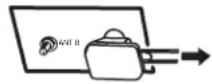
To outdoor VHF or UHF antenna
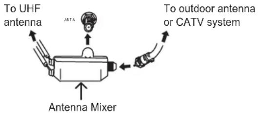
When both VHF and UHF antennas are connected
Attach an optional antenna cable mixer to the TV antenna terminal, and connect the cables to the antenna mixer. Consult your dealer or service store for the antenna mixer.
FRONT VIEW
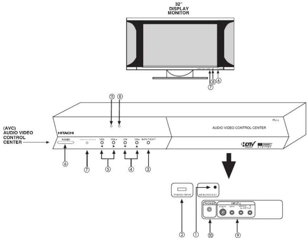
①MENU/SELECT button
This button allows you to enter the MENU, making it possible to set TV features to your preference without using the remote. This button also serves as the SELECT button when in MENU mode.
②PHOTO INPUT
Insert USB cable from your Digital Camera to view your digital still pictures (see pages 33-35).
③INPUT/EXIT button
Press this button to select the desired input, VIDEO 1 to 5, RGB, IEEE 1394, Photo Input or Ant A/B source. Your selection is shown in the top right corner of the screen. This button also serves as the EXIT button when in MENU mode.
④CHANNEL selector
Press these buttons until the desired channel appears in the top right corner of the TV screen. These buttons also serve as the cursor down (▼) and up (▲) buttons when in MENU mode.
⑤VOLUME level
Press these buttons to adjust the sound level. The volume level will be displayed on the TV screen. These buttons also serve as the cursor left (◀) and right (▶) buttons when in MENU mode.
⑥POWER button
Display Monitor "MAIN POWER" button
This power button is for the complete system, and must be turned ON/OFF manually. It is recommended to leave the "MAIN POWER" to ON condition (lights red) for stand-by mode.
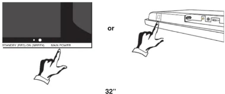
AVC POWER button
The AVC power can be turned ON/OFF manually or by remote control. Turning on the AVC Power will only turn on the AVC box if the "MAIN POWER" of the display monitor is off.
⑦POWER light indicator
To turn the monitor ON, press the main power switch located on the lower right side of the monitor. A red stand-by indicator lamp located on the lower right corner of the front bezel will illuminate. The LCD TV is now ready for remote on/off operation.
| Indicating Lamp | Power Status Operating | Rating |
| Off Off When the main power switch is set OFF. | ||
| Lights Red Off (Stand-by) monitor is ON, and the AVC Center is OFF. | ||
| Lights Green On Display monitor | MAIN POWER is ON and AVC Center power is ON. | |
| Lights Orange Off Display monitor (Power Saving) | MAIN POWER is ON and AVC Center power is ON, with no signal input except antenna (no sync. signal). | |
⑧REMOTE CONTROL sensor
Point your remote at this area when selecting channels, adjusting volume, etc.
⑨FRONT INPUT JACKS (for VIDEO: 5)
Use these audio/video jacks for a quick hook-up from a camcorder or VCR to instantly view your favorite show or new recording. Press the INPUTS button then use the CURSOR PAD and the SELECT button on the remote control to select INPUT 5. VIDEO: 5 appears in the top right corner of the TV screen. If you have mono sound, insert the audio cable into the left audio jack.
⑩PHONES JACK
Use this jack for your head-phones. The TV's internal speakers can also be heard. Turn off the internal speakers (see page 57) if you wish to listen to the head-phones only.
⑪ LEARNING AV NET Sensor
Point your equipment's remote control at this area while using the AV NET Learning Wizard.
NOTES: 1. Your HITACHI LCD TV will appear to be turned OFF (lights orange) if there is no video input when VIDEO: 1, 2, 3, 4, 5, or RGB is selected. Check the Power Light to make sure the Display Monitor is turned off or in Stand-by mode (lights red) when not in use.
- Remote Control can not turn ON/OFF the "MAIN POWER" of the display monitor.
Audio Video Control Center (AVC)
flowchart
graph TD
    A["Home Device"] --> B["Cable Cable™"]
    B --> C["Switch 1"]
    B --> D["Switch 2"]
    B --> E["Switch 3"]
    B --> F["Switch 4"]
    B --> G["Switch 5"]
    B --> H["Switch 6"]
    B --> I["Switch 7"]
    B --> J["Switch 8"]
    B --> K["Switch 9"]
    B --> L["Switch 10"]
    B --> M["Switch 11"]
    B --> N["Switch 12"]
    B --> O["Switch 13"]
    B --> P["Switch 14"]
    B --> Q["Switch 15"]
    B --> R["Switch 16"]
    B --> S["Switch 17"]
    B --> T["Switch 18"]
    B --> U["Switch 19"]
    B --> V["Switch 20"]
    B --> W["Switch 21"]
    B --> X["Switch 22"]
    B --> Y["Switch 23"]
    B --> Z["Switch 24"]
    B --> AA["Switch 25"]
    B --> AB["Switch 26"]
    B --> AC["Switch 27"]
    B --> AD["Switch 28"]
    B --> AE["Switch 29"]
    B --> AF["Switch 30"]
    B --> AG["Switch 31"]
    B --> AH["Switch 32"]
    B --> AI["Switch 33"]
    B --> AJ["Switch 34"]
    B --> AK["Switch 35"]
    B --> AL["Switch 36"]
    B --> AM["Switch 37"]
    B --> AN["Switch 38"]
    B --> AO["Switch 39"]
    B --> AP["Switch 40"]
    B --> AQ["Switch 41"]
    B --> AR["Switch 42"]
    B --> AS["Switch 43"]
    B --> AT["Switch 44"]
    B --> AU["Switch 45"]
    B --> AV["Switch 46"]
    B --> AW["Switch 47"]
    B --> AX["Switch 48"]
    B --> AY["Switch 49"]
    B --> AZ["Switch 50"]
32" Monitor Bottom View
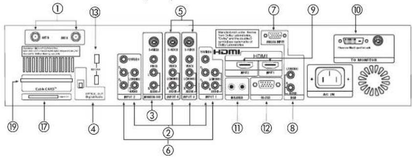
①Antenna Input
The remote control allows you to switch between two separate 75-Ohm RF antenna inputs, ANT A and ANT B. ANT A input can be displayed as a main picture or sub-picture. ANT B can only be displayed as a main picture (ANT B cannot be displayed as a sub-picture).
②Audio/Video Inputs 1, 2, 3 and 4
By using the INPUTS button, the CURSOR PAD, and the SELECT button of the remote control, you can select each video source. Use the audio and video inputs to connect external devices, such as VCRs, camcorders, laserdisc players, DVD players etc. (if you have mono sound, insert the audio cable into the left audio jack).
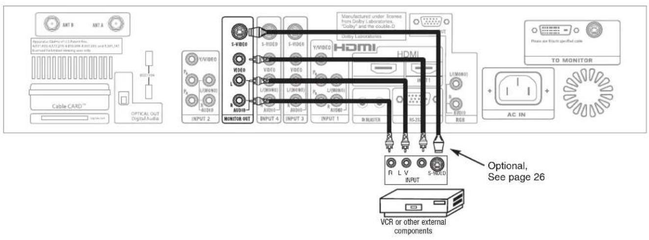
③MONITOR OUT
These jacks provide fixed audio and video signals (ANT A/B, INPUT 1\~5) which are used for recording. Use the S-VIDEO Output for high quality video output. Component signal to Input 1 and 2, RGB and HDMI inputs will not have monitor output.
④Optical Out (Digital Audio)
This jack provides Digital Audio Output for your audio device that is Dolby® Digital and PCM compatible, such as an audio amplifier.
⑤S-VIDEO Inputs 3 and 4
Inputs 3 and 4 provide S-VIDEO (Super Video) jacks for connecting equipment with S-VIDEO output capability.
NOTES: 1. You may use VIDEO or S-VIDEO inputs to connect to INPUT 3 and 4, but only one of these inputs may be used at a time.
2. S-VIDEO output may be used for recording, only when the input is of S-VIDEO type.
⑥Component: Y-P _B P _R Inputs
Inputs 1 and 2 provide Y- P_BP_R jacks for connecting equipment with this capability, such as a DVD player or Set Top Box. You may use composite video signal for INPUTS 1 and 2.
NOTES: 1. DO NOT connect composite VIDEO and S-VIDEO to Input 3, 4 or 5 at the same time. S-Video has a higher priority over video input.
2. Your component outputs may be labeled Y, B-Y, and R-Y. In this case, connect the components B-Y output to the AVC Box's P_B input and the components R-Y output to the AVC Box's P_R input.
3. Your component outputs may be labeled Y-C B C R . In this case, connect the component C B output to the AVC Box's P B input and the component C R output to the AVC Box's P R input.
4. It may be necessary to adjust TINT to obtain optimum picture quality when using the Y-P B P R inputs (See page 54).
5. To ensure no copyright infringement, the MONITOR OUT output will be abnormal, when using the Y-P B P R jacks, RGB and HDMI inputs.
⑦RGB - Analog Input
Use this 15-pin D-Sub input for your external devices with RGB output (see page 25).
⑧RGB - Audio Input
Connect audio for RGB input (if you have mono sound, insert the audio cable into the left audio jack).
⑨HDMI - Digital Input (INPUT 1 and INPUT 2)
About HDMI
HDMI is the next-generation all digital interface for consumer electronics. HDMI enables the secure distribution of uncompressed high-definition video and multi-channel audio in a single cable. Because digital television (DTV) signals remain in digital format, HDMI assures that pristine high-definition images retain the highest video quality from the source all the way to your television screen.
Use the HDMI input for your external devices such as Set-Top-Boxes or DVD players equipped with an HDMI output connection.
HDMI
HDMI, the HDMI logo and High-Definition Multimedia Interface are trademarks or registered trademarks of HDMI Licensing LLC.
NOTES: 1. The HDMI input is not intended for use with personal computers.
- Only DTV formats such as 1080i, 720p, 480i and 480p are available for HDMI input.
⑩To Monitor
Connect the Monitor Connection Cable to the AVC center's "TO MONITOR" connector, and to the display monitor's "FROM AVC" connector.
⑪IR Blaster
This jack provides IR output to your external components (VCR, Cable box, DVD player, etc.). With this connection, your external components can automatically be controlled by the A/V network feature. This connection will allow you to control the external components with your LCD Television's remote control in TV mode.
⑫RS232C Input
For use with third party home Audio/Video control systems which are commercially available. Please see your dealer regarding these “non Hitachi” home control systems (see page 76 to activate this input).
⑬IEEE1394
These jacks provide a digital interface for your external digital devices, such as a Digital VCR (D-VHS or Set-Top-Box) by means of a single cable (see page 20). When using IEEE1394 connections, you enable video and audio digital data exchange between a compatible device. This connection also enables you to control basic equipment functions (such as VCR play, rewind, fast forward, stop, etc.) from your TV On-Screen Display.
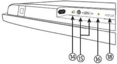
⑭Subwoofer Out
Connect this SUB WOOFER OUT output to the external audio component input using the sub woofer cable provided.
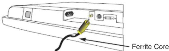
Sub-woofer cable (RCA Type)
⑮To AVC
Connect the Monitor Connection cable from the AVC center's "TO MONITOR" to these connectors ("FROM AVC").
⑯SUB-POWER button
This power is for serviceman usage.
⑰ Upgrade Card
This card slot is for future software upgrades. Hitachi will notify you if a software upgrade is required for your TV. In order to receive written notification, please complete and return your warranty card.
⑱To Power Swivel Connector
Connects to the Power Swivel Table Top Stand.
⑲CableCARD Slot
This slot is for the CableCARD that will be provided by your local cable operator to gain access to chosen cable channels. The CableCARD will allow you to tune digital and high definition cable channels. Please call your local cable operator if this service is available before requesting a CableCARD (also known as Point of Deployment (POD) module).
Connect a coaxial cable to ANT A terminal of the Rear Panel Jacks.
Insert the CableCARD into the slot (Top of card should be facing up as shown).
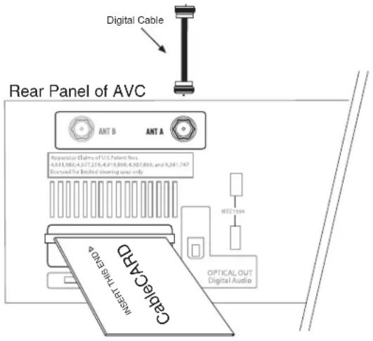
If the CableCARD is properly installed or not installed, the TV will display the following respective screens.
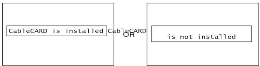
flowchart
graph TD
    A["CableCARD is installed"] --> B["OR"]
    B --> C["is not installed"]
After the CableCARD is installed, wait until the second screen below appears. The third screen below will appear if a channel is not authorized for viewing. Press the EXIT button to exit the second screen.

flowchart
graph LR
    A["Acquiring Data. Please wait."] --> B["In order to start cable service for this device, please contact your cable provider"]
    B --> C["Not an Authorized Channel"]
    B --> D["CableCARD(tm): 123-456-789-1\nHost: 123-456-789-1\nData: 123-456-789-1\nUnitAddress: 123-456-789-1"]
    D --> E["Press EXIT to return"]
Please take note of all information on the screen (you will provide this information to your cable operator). Call your cable operator and give them the information from the card to start your cable service.
NOTES: 1. A digital cable subscription is required.
- Antenna B will not be available when CableCARD is inserted.
- Do not insert a PCMCIA card into the CableCARD slot.
-
Please see pages 63-64 and 76 for additional CableCARD information.
-
From the owner's accessory you will find the Monitor Connector cable.
- Firmly, and securely insert the Monitor Connection Cable to the rear panel of the AVC box "TO MONITOR" connectors.
- Insert the other ends of the Monitor Connection Cable to the display monitor rear panel "FROM AVC" connectors.
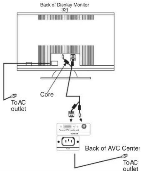
NOTE: The Display Monitor and the AVC Center have their own AC Power. Both AC cords must be completely plugged in to the AVC Center and the display monitor, then plug them in to the AC outlets.
CONNECTING EXTERNAL VIDEO SOURCES
The front panel jacks are provided as a convenience to allow you to easily connect a camcorder or VCR as shown in the following examples:
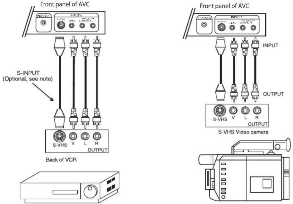
NOTES: 1. Completely insert connection cord plugs when connecting to front panel jacks. If you do not, the played back picture may be abnormal.
- If you have a S-VHS VCR, use the S-INPUT cable in place of the standard video cable.
- If you have a mono VCR, insert the audio cable into the left audio jack of your AVC box.
- S-VIDEO input takes priority over VIDEO input.
- If you have a VHS or 8mm camcorder, use the S-VIDEO cable in place of the VIDEO cable.
The exact arrangement you use to connect the VCR, camcorder, laserdisc player, DVD player, or HDTV Set Top Box to your LCD TV is dependent on the model and features of each component. Check the owner's manual of each component for the location of video and audio inputs and outputs.
The following connection diagrams are offered as suggestions. However, you may need to modify them to accommodate your particular assortment of components and features. For best performance, video and audio cables should be made from coaxial shielded wire.
Before Operating External Video Source
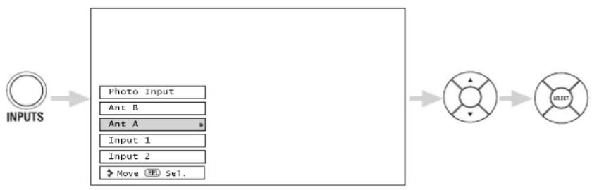
Connect an external source to one of the INPUT terminals, then press the INPUTS button to show the INPUTS menu. Use the CURSOR PAD to select the Antenna or Input of your choice. Then press the SELECT button to confirm your choice (see page 33).
flowchart
graph LR
    A["INPUTS"] --> B["Photo Input"]
    B --> C["Ant B"]
    C --> D["Ant A"]
    D --> E["Input 1"]
    D --> F["Input 2"]
    F --> G["Move SET Sel."]
    G --> H["Circle with directional arrows"]
    H --> I["Circle with directional arrows"]
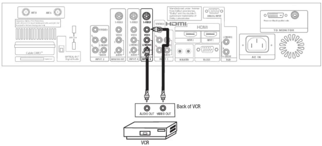
CONNECTING A MONAURAL AUDIO SOURCE TO INPUT1\~INPUT5
- Connect the cable from the VIDEO OUT of the VCR or the laserdisc player to the INPUT (VIDEO) jack, as shown on the AVC Center below.
- Connect the cable from the AUDIO OUT of the VCR or the laserdisc player to the INPUT (MONO)/L(AUDIO) jack.
- Press the INPUTS button, then select INPUT 3 from the INPUTS menu to view the program from the VCR or the laserdisc player. The VIDEO label disappears automatically after approximately four seconds.
- Select Ant A or B from the INPUTS menu to return to the previous channel.
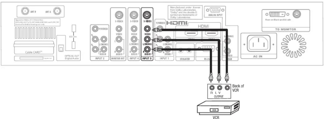
CONNECTING A STEREO VCR OR STEREO LASERDISC PLAYER
- Connect the cable from the VIDEO OUT of the VCR or the laserdisc player to the INPUT (VIDEO) jack, as shown on the AVC Center below.
- Connect the cable from the AUDIO OUT R of the VCR or the laserdisc player to the INPUT (AUDIO/R) jack.
- Connect the cable from the AUDIO OUT L of the VCR or the laserdisc player to the INPUT (AUDIO/L) jack.
- Press the INPUTS button, then select INPUT 3 from the INPUTS menu to view the program from the VCR or laserdisc player. The VIDEO label disappears automatically after approximately four seconds.
- Select ANT A or B from the INPUTS menu to return to the previous channel.
NOTES:
- Completely insert the connection cord plugs when connecting to rear panel jacks. The picture and sound that is played back will be abnormal if the connection is loose.
- A single VCR can be used for VCR #1 and VCR #2, but note that a VCR cannot record its own video or line output (INPUT: 4 in example on page 25). Refer to your VCR operating guide for more information on line input-output connections.
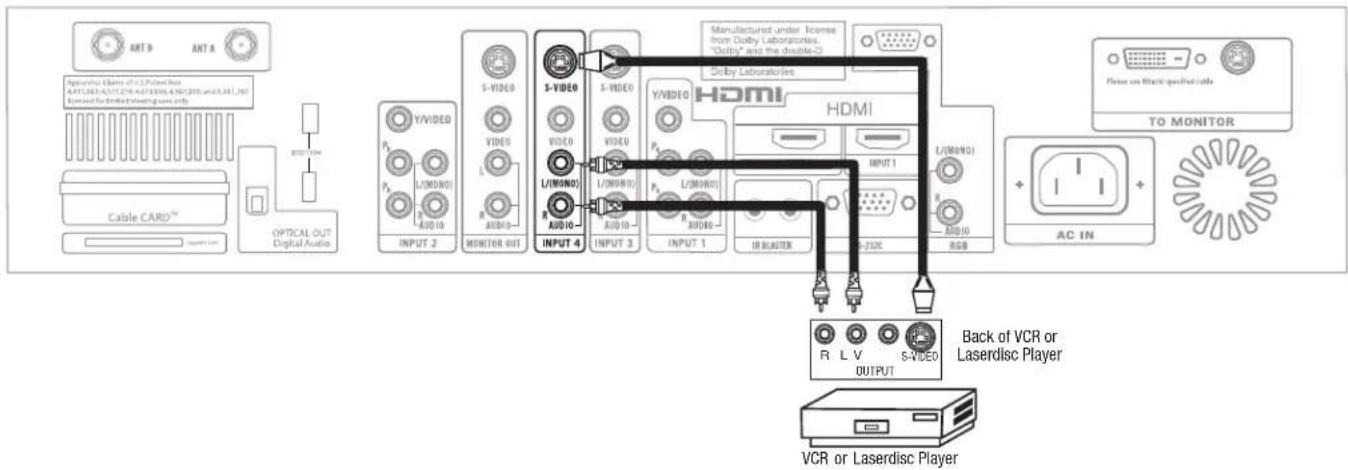
CONNECTING S-VIDEO VCR OR LASERDISC PLAYER
- Connect the cable from the S-VIDEO OUT of the S-VHS VCR or the laserdisc player to the INPUT (S-VIDEO) jack, as shown on the AVC Center below.
- Connect the cable from the AUDIO OUT R of the VCR or the laserdisc player to the INPUT (AUDIO/R) jack.
- Connect the cable from the AUDIO OUT L of the VCR or the laserdisc player to the INPUT (AUDIO/L) jack.
- Press the INPUTS button, then select INPUT 4 from the INPUTS menu to view the program from the VCR or laserdisc player. The VIDEO label disappears automatically after approximately four seconds.
- Select ANT A or B from the INPUTS menu to return to the previous channel.
NOTES:
- Completely insert the connection cord plugs when connecting to rear panel jacks. The picture and sound that is played back will be abnormal if the connection is loose.
- A single VCR can be used for VCR #1 and VCR #2, but note that a VCR cannot record its own video or line output (INPUT: 4 in example on page 25). Refer to your VCR operating guide for more information on line input-output connections.
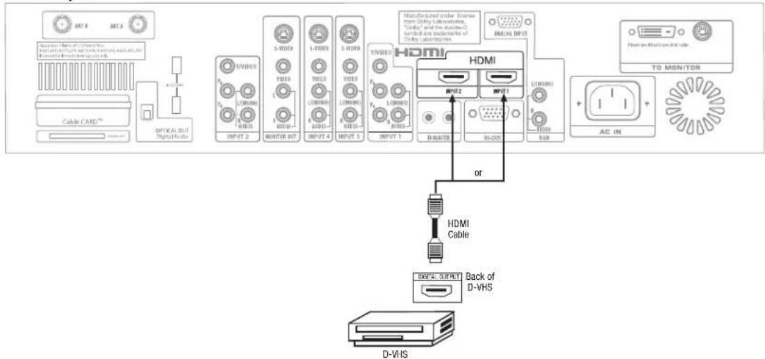
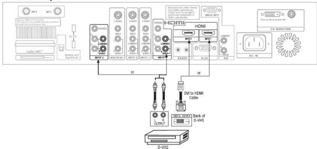
CONNECTING A COMPONENT SOURCE WITH HDMI or DVI CAPABILITY TO INPUT 1 or INPUT 2
- Connect the HDMI or DVI to HDMI connection cable from the output of the HDTV set top box or DVD player to the HDMI input as shown on the AVC Center below.
- With DVI output, connect the cable from the AUDIO OUT R of the HDTV set top box or DVD player to the INPUT (AUDIO/R) jack.
- With DVI output, connect the cable from the AUDIO OUT L of the HDTV set top box or DVD player to the INPUT (AUDIO/L) jack.
- Press the INPUTS button, then select INPUTS 1 or 2 to view the program from the HDTV set top box or DVD player. The VIDEO OSD label disappears automatically after approximately four seconds.
- Select ANT A or B from the INPUTS menu to return to the previous channel.
HDMI input
flowchart
graph TD
    A["Ant 6"] --> B["Cable CARD™"]
    C["Ant 4"] --> D["Optical OUT Digital Audio"]
    B --> E["INPUT 2"]
    D --> F["INPUT 3"]
    E --> G["3-VIDEO"]
    F --> H["3-VIDEO"]
    G --> I["1-VIDEO"]
    H --> J["1-VIDEO"]
    I --> K["1-VIDEO"]
    J --> L["1-VIDEO"]
    K --> M["1-VIDEO"]
    L --> N["1-VIDEO"]
    M --> O["1-VIDEO"]
    N --> P["1-VIDEO"]
    O --> Q["1-VIDEO"]
    P --> R["1-VIDEO"]
    Q --> S["INPUT 1"]
    R --> T["INPUT 1"]
    S --> U["HDMI"]
    T --> V["HDMI"]
    U --> W["BRACTER"]
    V --> X["RS-DISC"]
    W --> Y["+"]
    X --> Z["+"]
    Y --> AA["AC IN"]
    Z --> AB["+"]
    AC["TO MONITOR"] --> AD["Power Watchset Interface"]
    AE["Back of D-VHS"] --> AF["D-VHS"]
DVI to HDMI Input
flowchart
graph TD
    A["AT8"] --> B["CYCLE CABLE™"]
    C["AT4"] --> D["OPTICAL OUT Digital Audio"]
    B --> E["INPUT 2"]
    D --> E
    E --> F["OUTPUT"]
    F --> G["1/VDDO"]
    G --> H["L/WDMO"]
    H --> I["AUDIO"]
    I --> J["MONITOR OUT"]
    K["3/VDDO"] --> L["L/WDMO"]
    M["3/VDDO"] --> N["L/WDMO"]
    O["3/VDDO"] --> P["L/WDMO"]
    Q["3/VDDO"] --> R["L/WDMO"]
    S["3/VDDO"] --> T["L/WDMO"]
    U["3/VDDO"] --> V["L/WDMO"]
    W["3/VDDO"] --> X["L/WDMO"]
    Y["3/VDDO"] --> Z["L/WDMO"]
    AA["3/VDDO"] --> AB["L/WDMO"]
    AC["3/VDDO"] --> AD["L/WDMO"]
    AE["3/VDDO"] --> AF["L/WDMO"]
    AG["3/VDDO"] --> AH["L/WDMO"]
    AI["3/VDDO"] --> AJ["L/WDMO"]
    AK["3/VDDO"] --> AL["L/WDMO"]
    AM["3/VDDO"] --> AN["L/WDMO"]
    AO["3/VDDO"] --> AP["L/WDMO"]
    AQ["3/VDDO"] --> AR["L/WDMO"]
    AS["3/VDDO"] --> AT["L/WDMO"]
    AU["3/VDDO"] --> AV["L/WDMO"]
    AW["3/VDDO"] --> AX["L/WDMO"]
    AY["MANUFACTURED UNDER HOMES FROM DAIRY LABORATIONS, "Duty" and the double-iodo-griculture Incentrations of DAIRY LABORATIONS"] --> AZ["HDMI"]
    BA["ANEXCEL INPUT"] --> BB["HDMI"]
    BC["DVI to HDMI Cable"] --> BD["DVI to HDMI Cable"]
    BE["DVI to HDMI Cable"] --> BF["DVI to HDMI Cable"]
    BG["DVI to HDMI Cable"] --> BH["DVI to HDMI Cable"]
    BI["DVI to HDMI Cable"] --> BJ["DVI to HDMI Cable"]
NOTES:
- Completely insert the connection cord plugs when connecting to rear panel jacks. The picture and sound that is played back will be abnormal if the connection is loose.
- The HDMI input on INPUT 1 or 2 contains the copy protection system called High-bandwidth Digital Content Protection (HDCP). HDCP is a cryptographic system that encrypts video signals when using HDMI connections to prevent illegal copying of video contents.
- HDMI is not a "NETWORK" technology. It establishes a one-way point-to-point connection for delivery of uncompressed video to a display.
- The connected digital output device controls the HDMI interface so proper set-up of device user settings determines final video appearance.
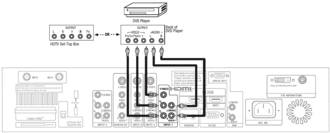
CONNECTING A STEREO LASERDISC/DVD PLAYER OR HDTV SET TOP BOX TO INPUT 1 OR 2 COMPONENT: Y-R _B P _R .
- Connect the cable from the Y OUT of the Laserdisc/DVD player or HDTV set top box to the INPUT (Y) jack, as shown on the AVC Center below.
- Connect the cable from the C B/PB OUT or B-Y OUT of the Laserdisc/DVD player or HDTV set top box to the INPUT (PB)jack.
- Connect the cable from the C R/PR OUT or R-Y OUT of the Laserdisc/DVD player or HDTV set top box to the INPUT ( P_R ) jack.
- Connect the cable from the AUDIO OUT R of the Laserdisc/DVD player or HDTV set top box to the INPUT (AUDIO/R) jack.
- Connect the cable from the AUDIO OUT L of the Laserdisc/DVD player or HDTV set top box to the INPUT (AUDIO/L) jack.
- Press the INPUTS button, then select INPUT 1 or 2 from the INPUTS menu to view the program from the Laserdisc/DVD player or HDTV set top box. The VIDEO label disappears automatically after approximately four seconds.
- Select ANT A or B to return to the previous channel.
flowchart
graph TD
    A["DVD Player"] -->|OR| B["HDTV Set-Top Box"]
    B --> C["OUTPUT"]
    C --> D["Back of DVD Player"]
    D --> E["Analog Input"]
    E --> F["AC IN"]
    F --> G["TO MONITOR"]
    G --> H["Output"]
    style A fill:#f9f,stroke:#333
    style B fill:#ccf,stroke:#333
    style C fill:#cfc,stroke:#333
    style D fill:#fcc,stroke:#333
    style E fill:#cff,stroke:#333
    style F fill:#ffc,stroke:#333
    style G fill:#cfc,stroke:#333
    style H fill:#fcc,stroke:#333
NOTE: 1. Completely insert the connection cord plugs when connecting to rear panel jacks. The picture and sound that is played back will be abnormal if the connection is loose.
- See page 26 for tips on REAR PANEL CONNECTIONS.
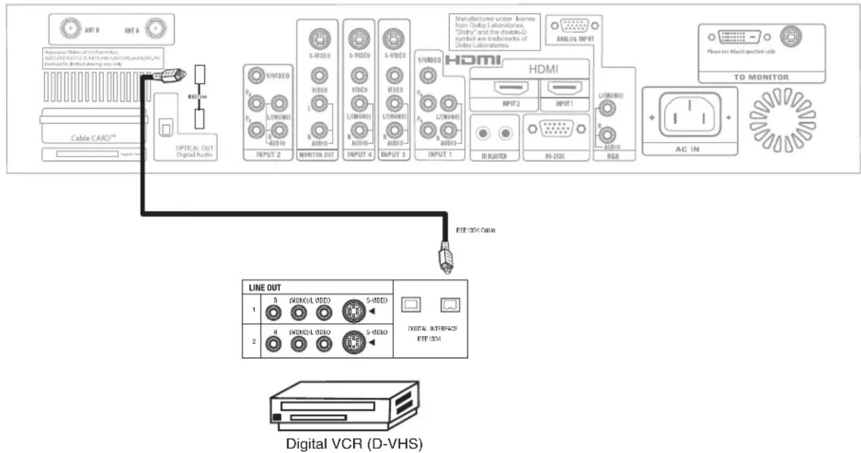
CONNECTING A COMPONENT SOURCE WITH DIGITAL INTERFACE CAPABILITY TO IEEE1394 TERMINALS
-
Connect the IEEE1394 cable from the output of the component with IEEE1394 capability, such as a Set-Top-Box or Digital VCR, to the IEEE1394 input terminals shown on the AVC Center below. IEEE 1394 allows the LCD television and the external device to communicate with one another. When using IEEE1394 connections, you enable video and audio digital data exchange between a compatible device. This connection also enables you to control basic equipment functions (such as VCR play, rewind, fast forward, stop, etc.) from your TV On-Screen Display.
-
Press the INPUTS button on the Remote Control.
- Select the IEEE1394 option (see page 36).
flowchart
graph TD
    A["APPROVATOR ON/OFFIC LUX"] --> B["Cable CARD™"]
    B --> C["OPTICAL OUT Digital Audio"]
    C --> D["LINE OUT"]
    D --> E["Digital VCR (D-VHS)"]
    subgraph Line_OUT
        F["1: N MONKOL VIDEO"] --> G["2: R MONKOL VIDEO"]
        H["S-VIDEO"] --> I["3: S-VIDEO"]
        J["DIGITAL INTERFACE IEF-ISM"] --> K["4: S-VIDEO"]
    end
    subgraph IEF-ISM Cable
        L["INPUT 2: Y/VIDEO, VIDE, S-VIDEO, VIDE, VIDE, VIDE, VIDE, VIDE, VIDE, VIDE, VIDE"] --> M["INPUT 4: Y/VIDEO, VIDE, VIDE, VIDE, VIDE, VIDE, VIDE, VIDE, VIDE, VIDE"] --> N["INPUT 3: Y/VIDEO, VIDE, VIDE, VIDE, VIDE, VIDE"] --> O["INPUT 1: HDMI"]
    end
    subgraph Digital VCR
        P["1: N MONKOL VIDEO"] --> Q["2: R MONKOL VIDEO"]
        R["S-VIDEO"] --> S["3: S-VIDEO"]
        T["DIGITAL INTERFACE IEF-ISM"] --> U["4: S-VIDEO"]
    end
    subgraph HDMI
        V["INPUT 2: HMI"]
        W["INPUT 1: HDMI"]
        X["IR BLASTER"] --> Y["RS-2026"]
        Z["AUDIO"] --> AA["RGB"]
        AB["ANALOG INPUT"] --> AC["Please to Launch specified cable"]
        AD["TO MONITOR"] --> AE["AC IN"]
    end
NOTES:
- This LCD TV's IEEE1394 connection is not compatible with a DV camcorder (Digital Video camcorder) and a PC.
- With IEEE1394 connection, video and audio will be received by the TV. It will enable you to control the D-VHS from the TV IEEE1394 menu (see page 36).
- The IEEE1394 interface contains the copy protection standard called 5C or Digital Transmission Content Protection (DTCP).
- See page 26 for tips on Rear Panel Connections.
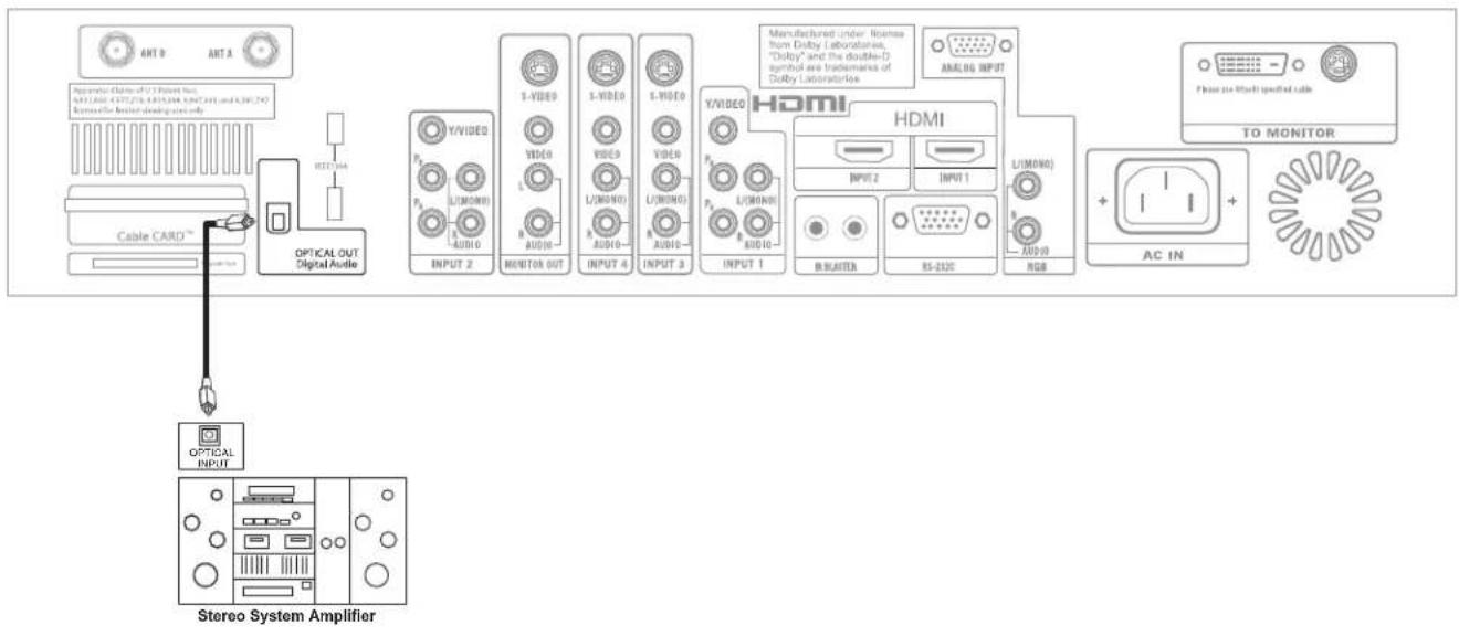
CONNECTING EXTERNAL AUDIO AMPLIFIER
To monitor the audio level of the LCD TV to an external audio amplifier, connect the system as shown below. The "OPTICAL OUT" from the AVC center is a fixed output. The Volume of the amplifier is controlled by the amplifier, not by the LCD Television. The OPTICAL OUT terminal outputs all audio sources with Optical IN capability.
flowchart
graph TD
    A["Cable CARD™"] --> B["OPTICAL OUT Digital Audio"]
    B --> C["Optical INPUT"]
    C --> D["Stereo System Amplifier"]
    D --> E["Microcontroller 2"]
    E --> F["Microcontroller 3"]
    F --> G["HDMI"]
    G --> H["Analog Input"]
    H --> I["AC IN"]
    I --> J["TO MONITOR"]
    J --> K["Phone to Multi-specific cable"]
The MONITOR OUT terminal outputs video and audio of ANT A/B and INPUTS 1, 2, 3, 4 and 5. It does not output component video, HDMI or RGB.
Your Hitachi LCD Television is equipped with an AV Network feature. This feature helps to control your external Audio/Video equipment (VCR, Set Top Box, DVD, etc.). Once this is setup, it allows your IR Mouse connector to control your equipment using your Hitachi LCD TV Remote Control. You can use your Hitachi remote control to control the Audio/Video equipment command without the equipment's remote control.
The LCD Television AVC Center has 2 IR BLASTER jacks. Each IR Mouse cable can connect up to 2 external Audio/Video components. Therefore, you can connect the LCD Television with up to four components. Please see the following example of an AV Network setup between your Hitachi LCD Television and external Audio/Video equipment (VCR and DVD Player).
CONNECTING EXTERNAL AUDIO/VIDEO COMPONENTS TO IR BLASTER FOR AV NETWORK
- Connect your external Audio/Video components to the AVC Center shown on pages 15\~21.
- Connect the IR Mouse cable to the IR BLASTER output of the AVC Center.
- Place the IR mouse in front of the infrared sensor of the external components you wish to control.
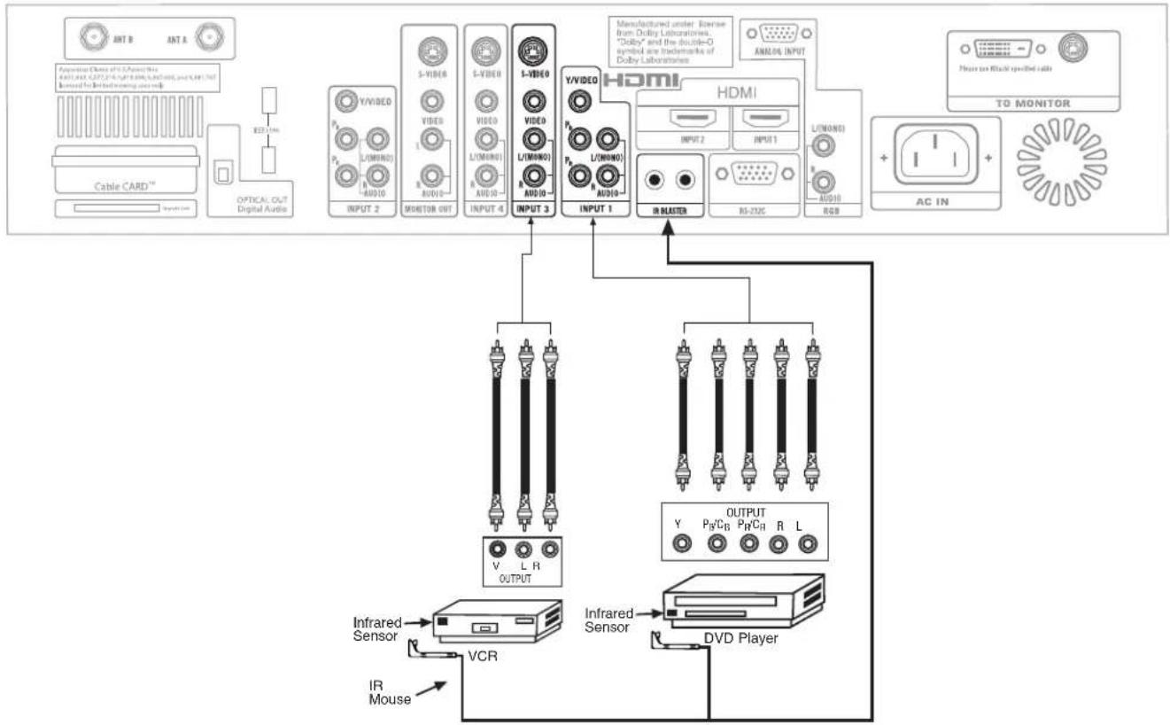
flowchart
graph TD
    A["Ant B"] --> B["Optical OUT Digital Audio"]
    C["Ant A"] --> B
    D["Cable CARD™"] --> B
    B --> E["INPUT 2"]
    E --> F["MONITOR OUT"]
    F --> G["INPUT 4"]
    G --> H["INPUT 3"]
    H --> I["INPUT 1"]
    I --> J["HDMI"]
    J --> K["INPUT 2"]
    K --> L["RS-232C"]
    L --> M["RGB"]
    M --> N["AC IN"]
    N --> O["TO MONITOR"]
    P["Infrared Sensor"] --> Q["VCR"]
    R["IR Mouse"] --> Q
    Q --> S["DVD Player"]
    T["INfrared Sensor"] --> U["OUTPUT Y"]
    V["Infrared Sensor"] --> W["PH/CB"]
    X["Infrared Sensor"] --> Y["PH/CR"]
    Z["Infrared Sensor"] --> AA["R"]
    AB["Manufactured under Exercise from Dolby Laboratories, "Dolby" and the double-O symbol are trademarks of Dolby Laboratories"] --> AC["ANALOG INPUT"]
    AD["Infrared Sensor"] --> AE["V"]
    AF["Infrared Sensor"] --> AG["L"]
    AH["Infrared Sensor"] --> AI["R"]
    AJ["Infrared Sensor"] --> AK["L (M)"]
    AL["Infrared Sensor"] --> AM["L (M)"]
    AN["Infrared Sensor"] --> AO["L (M)"]
    AP["Infrared Sensor"] --> AQ["L (M)"]
    AR["Infrared Sensor"] --> AS["L (M)"]
    AT["Infrared Sensor"] --> AU["L (M)"]
    AV["Infrared Sensor"] --> AW["L (M)"]
    AX["Infrared Sensor"] --> AY["L (M)"]
    AZ["Infrared Sensor"] --> BA["L (M)"]
    BB["Infrared Sensor"] --> BC["L (M)"]
    BD["Infrared Sensor"] --> BE["L (M)"]
    BF["Infrared Sensor"] --> BG["L (M)"]
    BH["Infrared Sensor"] --> BI["L (M)"]
    BJ["Infrared Sensor"] --> BK["L (M)"]
    BL["Infrared Sensor"] --> BLA["L (M)"]
    BM["Infrared Sensor"] --> BN["L (M)"]
    BO["Infrared Sensor"] --> BP["L (M)"]
    BP["Infrared Sensor"] --> BQ["L (M)"]
    BR["Infrared Sensor"] --> BS["L (M)"]
    BT["Infrared Sensor"] --> BU["L (M)"]
    BV["Infrared Sensor"] --> BW["L (M)"]
    BX["Infrared Sensor"] --> BY["L (M)"]
    BZ["Infrared Sensor"] --> BZL["V"]
    BN["Infrared Sensor"] --> BNL["V"]
    BO["Infrared Sensor"] --> BOL["V"]
    BP["Infrared Sensor"] --> BPL["V"]
    BB["Infrared Sensor"] --> BBL["V"]
- Press the AV NET button on the remote control. Use CURSOR PAD ▲ or ▼ to select and highlight the Device Setup
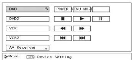
NOTES:
- The AVC Center has two IR BLASTER outputs which can control up to a total of four external components.
- The IR Mouse must be placed in front of the external components infrared sensor for the AV Network to work.
- The correct codes must be entered for each of the Audio/Video components for the AV Network to function properly.
-
Audio/Video component codes for AV network are on page 24.
-
Follow the steps below to setup your AV network (See page 24 for AV Network Codes).
SETUP PROCEDURE (DVD setup example below).
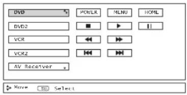
- Press the A/V Net button on the remote control.
![PV Recorder * Cable Box Set Top Box Custom Device Setup * Move [ED] Select](/content/2026/06/1147412/images/36cfd91f23d6a61a40e6248048cef371bae44038d053506f3fec9b7847887348.jpg)
- Use CURSOR PAD ▲, ▼ to select Device Setup.
- Press the SELECT button on the remote control.
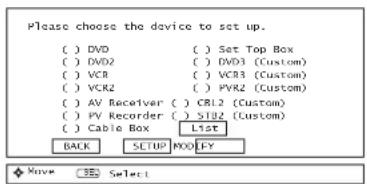
- Use the CURSOR PAD ▲, ▼ to choose DVD and press the SELECT button on the remote control.
- Cursor down to SETUP and press the SELECT button on the remote control. LIST: Select to view the list of devices that are setup.
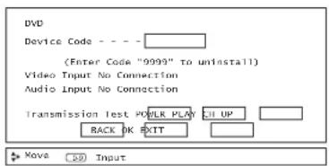
- Using the remote, enter the four digit Device Code for your equipment, found on page 24.
- Using the CURSOR PAD, set the Video and Audio Inputs to the INPUT to which your device is connected.
- Perform a Transmission Test by selecting Power, Play, or CH UP softkeys. If the device responds, then it is properly set up. Select OK. (If the Transmission Test failed, try another code.)
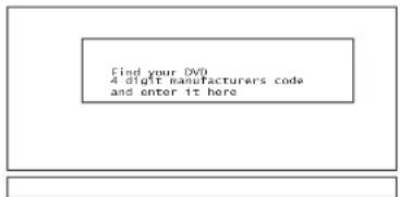
- If "OK" was selected, and the 4 digit code was invalid, the screen on the left appears, then goes back to the device entry screen.
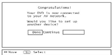
- Select CONTINUE to setup another device.
- Select DONE to finish and the following screen appears.
- Select EXIT to quit.
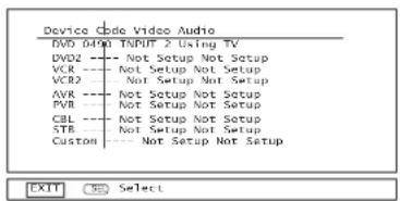
- See Remote Control AV NET button usage on pages 31 and 32.
FIRST TIME USE
| VCR BRAND | CODE |
| Admiral | 0048, 0209 |
| Adventura | 0000 |
| Aiko | 0278 |
| Awa | 0000, 0037 |
| Akai | 0041 |
| America Action | 0278 |
| American High | 0035 |
| Asha | 0240 |
| Audiovox | 0037, 0278 |
| Beaumark | 0240 |
| Bell & Howell | 0104 |
| Broksonic | 0121, 0184, 0002, 0209,0479, 1479, 0278 |
| CCE | 0072, 0278 |
| Calix | 0037 |
| Canon | 0035 |
| Carver | 0081 |
| Cineral | 0278 |
| Citizen | 0278, 0037, 1278 |
| Colt | 0072 |
| Craig | 0037, 0072, 0047, 0240 |
| Curtis Mathes | 0035, 0041, 0060, 0162, 0760, 1035 |
| Cybermex | 0240 |
| Daewoo | 0278, 1278, 0045 |
| Denon | 0042 |
| Dynatech | 0000 |
| Electrohome | 0037 |
| Electrophonic | 0037 |
| Emerex | 0032 |
| Emerson | 0184, 0002, 0209,0121, 0000, 0037, 0043 |
| Fisher | 0104, 0047 |
| Fuji | 0033, 0035 |
| Funai | 0000 |
| GE | 0035, 0060, 0240, 0760, 0807, 1035, 1060 |
| Gamard | 0000 |
| Go Video | 0432 |
| GoldStar | 0037, 0038, 1237 |
| Gradiente | 0000 |
| Hi-Q | 0047 |
| Harley Davidson | 0000 |
| Harman/Kardon | 0038, 0081 |
| Harwood | 0072 |
| Hitachi | 0000, 0041, 0042 |
| Hughes Network Systems | 0042 |
| JVC | 0067, 0041 |
| Jensen | 0041 |
| KEC | 0037, 0278 |
| KLH | 0072 |
| Kenwood | 0041, 0067, 0038 |
| Kodak | 0035, 0037 |
| LXI | 0037 |
| Lloyd's | 0000 |
| Logik | 0072 |
| MEI | 0035 |
| MGA | 0043, 0240 |
| MGN Technology | 0240 |
| MTC | 0000, 0240 |
| Magnasonic | 1278 |
| Magnavox | 0035, 0081, 0563,0000, 0039, 0149, 1781 |
| Magnin | 0240 |
| Marantz | 0081, 0035 |
| Marla | 0037 |
| Matsushita | 0035, 0162, 0454 |
| Memorex | 0047, 0037, 0104, 0209,0454,0048, 0039, 0240, 0000,0479, 1037, 1162, 1237, 1262 |
| Minolta | 0042 |
| Mitsubishi | 0043, 0067 |
| Motorola | 0035, 0048 |
| Multitech | 0000, 0072 |
| NEC | 0038, 0041, 0067, 0104 |
| Nikko | 0037 |
| Noblex | 0240 |
| Olympus | 0035 |
| Optimus | 1062, 0162, 0037, 0048,0104, 0432, 0454, 1048, 1162, 1262 |
| Orion | 0184, 0209, 0002, 0479, 1479 |
| Panasonic | 1062, 0035, 0225, 0454,0616, 1035, 1162, 1262 |
| Penney | 0035, 0037, 0240, 0042,0038, 1035, 1237 |
| Pentax | 0042 |
| Philco | 0035, 0209, 0479 |
| Phillips | 0081, 0035, 0618, 1081, 1181 |
| Pilot | 0037 |
| Pioneer | 0067 |
| Polk Audio | 0081 |
| Profitronic | 0240 |
| Proscan | 0060, 0760, 1060 |
| Protec | 0072 |
| Pulsar | 0039 |
| Quasar | 0035, 0162, 0454, 1035, 1182 |
| RCA | 0060, 0240, 0042, 0149,0760, 1035, 1060 |
| Radio Shack | 0000, 1037 |
| Radix | 0037 |
| Randex | 0037 |
| Realistic | 0035, 0037, 0048, 0047, 0000, 0104 |
| ReplayTV | 0614, 0616 |
| Runco | 0039 |
| STS | 0042 |
| Samsung | 0045, 0240 |
| Sanky | 0038, 0048 |
| Sansui | 0000, 0067, 0209, 0041, 0479, 1479 |
| Sanyo | 0047, 0240, 0104 |
| Scott | 0184, 0045, 0121, 0043 |
| Sears | 0035, 0037, 0047, 0000, 0042, 0104, 1237 |
| Semp | 0045 |
| Sharp | 0048, 0848 |
| Shintom | 0072 |
| Shogun | 0240 |
| Singer | 0072 |
| Sonic Blue | 0614, 0616 |
| Sony | 0035, 0032, 0000, 0033, 0636, 1032, 1232 |
| Sylvania | 0035, 0081, 0000, 0043, 1781 |
| Symphonic | 0000 |
| TMK | 0240 |
| Tatung | 0041 |
| Teac | 0000, 0041 |
| Technics | 0035, 0162 |
| Teknika | 0000, 0035, 0037 |
| Thomas | 0000 |
| Tivo | 0618, 0636 |
| Toshiba | 0045, 0043 |
| Totevision | 0037, 0240 |
| Unitech | 0240 |
| Vector | 0045 |
| Vector Research | 0038 |
| Video Concepts | 0045 |
| Videomagic | 0037 |
| Videosonic | 0240 |
| Wards | 0060, 0035, 0048, 0047, 0081, 0240, 0000, 0042, 0072, 0149, 0760 |
| White Westinghouse | 0072, 1278, 0209 XR-1000 0072, 0000, 0035 |
| Yamaha | 0036 |
| Zenith | 0039, 0000, 0209, 0033 0479, 1479, 0033, 0209, 0479 |
| DVD BRAND | CODE |
| Alwa | 0641 |
| Apex | 0672, 0717, 0755, 0794,0795, 0796, 0797, 0830 |
| Audiologic | 0736 |
| B & K | 0655, 0662 |
| Blue Parade | 0571 |
| Brooksonic | 0695 |
| DVD2000 | 0521 |
| Daewoo | 0784 |
| Denon | 0490, 0634 |
| Emerson | 0591 |
| Enterprise | 0591 |
| Fisher | 0670 |
| GE | 0522, 0717, 0815 |
| GPX | 0769 |
| Go Video | 0715 |
| Gradiente | 0651 |
| Greenhill | 0717 |
| Haman/Kardon | 0582, 0702 |
| Hitachi | 0490, 0573, 0664 |
| Hitaker | 0672 |
| JBL | 0702 |
| JVC | 0623, 0558, 0867 |
| KLH | 0717 |
| Kenwood | 0490, 0534, 0682 |
| Konka | 0711, 0719, 0721 |
| Koss | 0651 |
| Lasonic | 0798 |
| Magnavox | 0503, 0675 |
| Malata | 0782 |
| Marantz | 0539 |
| Microsoft | 0522 |
| Mintek | 0717 |
| Mitsubishi | 0521 |
| Nusa | 0717 |
| Onkyo | 0627, 0503 |
| Oritron | 0651 |
| Panasonic | 0490, 1362, 0632 |
| Philips | 0503, 0539, 0646, 0854 |
| Pioneer | 0525, 0571, 0632 |
| Polk Audio | 0539 |
| Princeton | 0674 |
| Proscan | 0622 |
| RCA | 0522, 0571, 1022, 0717 |
| Rowa | 0823 |
| Sampo | 0698 |
| Samsung | 0573, 0820 |
| Sansul | 0695 |
| Sanyo | 0670 |
| Sharp | 0630 |
| Sherwood | 0633 |
| Sony | 0533 |
| Sylvania | 0675 |
| Technics | 0490 |
| Techwood | 0692 |
| Theta Digital | 0571 |
| Toshiba | 0503, 0695 |
| Urban Concepts | 0503 |
| Yamaha | 0490, 0545, 0539 |
| Zenith | 0591, 0503 |
| CABLE BRAND | CODE |
| ABC | 0003, 0008, 0014, 0017 |
| Americas | |
| Bell & Howel | 0014 |
| Bell South | 0899 |
| Director | 0476 |
| General Instrument | 0003, 0476, 0276, 0810 |
| GoldStar | 0144 |
| Hannin | 0009, 0273 |
| Jerrold | 0476, 0003, 0276, 0012, 0014, 0810 |
| Memorex | 0000 |
| Motorola | 0476, 1106, 0276, 0810 |
| Pace | 0237 |
| Panasonic | 0107, 0000 |
| Phillips | 0305, 0317 |
| Pioneer | 0144, 0533, 0877, 1877 |
| Pulsar | 0000 |
| Quasar | 0000 |
| Regal | 0273, 0279 |
| Runco | 0000 |
| Samsung | 0144 |
| Scientific Atlanta | 0877, 0008, 0017, 0477, 1877 |
| Sony | 1006 |
| Starcom | 0003 |
| Supercable | 0276 |
| Tocom | 0012 |
| Torx | 0003 |
| Toshiba | 0000 |
| Zenith | 0000, 0525, 0899 |
| SATELLITE BRAND (Set-Top-Box) | CODE | |
| AlphaStar | 0772 | |
| Chapparral | 0216 | |
| Crossdigital | 1109 | |
| DishPro | 1005, 0775 | |
| Echostar | 1005, 0775 | |
| Expressvu | 0775 | |
| GE | 0566 | |
| GOI | 0775 | |
| General Instrument | 0869 | |
| HTS | 0775 | |
| Hitachi | 0819 | |
| Hughes Network Systems | 1142, 0749, 1749 | |
| JVC | 0775 | |
| Magnavox | 0724, 0722 | |
| Memorex | 0724 | |
| Mitsubishi | 0749 | |
| Motorola | 0869 | |
| Next Level | 0869 | |
| Panasonic | 0247, 0701 | |
| Paysat | 0724 | |
| Phillips | 1142, 0749, 0724, 1078, 0722, 1749 | |
| Proscan | 0392 | |
| RCA | 0392, 0566, 0855, 0143 | |
| Radioshack | 0869 | |
| SKY | 0856 | |
| Samsung | 1109 | |
| Sony | 0639 | |
| Star Choice | 0869 | |
| Toshiba | 0749, 0790, 1749 | |
| Uniden | 0724, 0722 | |
| Zenith | 0856, 1856 | |
| AMPLIFIER BRAND | CODE |
| Alwa | 0406 |
| Bose | 0674 |
| Carver | 0269 |
| Curtis Mathes | 0300 |
| Denon | 0160 |
| GE | 0078 |
| Harman/Kardon | 0892 |
| JVC | 0331 |
| Left Coast | 0892 |
| Linn | 0269 |
| Luxman | 0165 |
| Magnavox | 0269 |
| Marantz | 0269, 0321, 0892 |
| NEC | 0264 |
| Nakamichi | 0321 |
| Optimus | 0395, 0300 |
| Panasonic | 0308, 0521 |
| Parasound | 0246 |
| Philips | 0269, 0892 |
| Pioneer | 0013, 0300 |
| Polk Audio | 0269, 0892 |
| RCA | 0300 |
| Realistic | 0395 |
| Sansui | 0321 |
| Shure | 0264 |
| Sony | 0689, 0220 |
| Soundesign | 0078, 0211 |
| Technics | 0308, 0521 |
| Victor | 0331 |
| Wards | 0013, 0078, 0211 |
| Yamaha | 0354, 0133 |
| RECEIVER BRAND (Amplifier) | CODE | |
| ADC | 0531 | |
| Adcom | 0616 | |
| Alwa. | 1089, 1405, 0121, 0158,0189, 0405, 1321, 1388 | |
| Akai. | 0076, 0224 | |
| Alco | 1390 | |
| Anam. | 1074, 1609 | |
| Apex Digital. | 1257 | |
| Arcam | 1120 | |
| Audiotronic | 1189 | |
| Audiovox | 1390 | |
| Bose | 1229 | |
| Capeltronic | 0531 | |
| Carver. | 1089, 1189, 0008, 0042, 0189, 0360 | |
| Casio. | 0195 | |
| Celestion | 1264 | |
| Clarinette | 0195 | |
| Compaq. | 1136 | |
| Curtis Mathes | 0080 | |
| Denon. | 1104, 0004, 0273, 0771, 1311, 1360 | |
| Emerson | 0424 | |
| Fisher. | 0042, 0219, 0360 | |
| GPX. | 1299 | |
| Garrard. | 0424, 0463 | |
| Glory Horse. | 1263 | |
| Harman/Kardon. | 0891, 0110, 0189 | |
| Hewlett Packard. | 1181 | |
| Inkel. | 0062 | |
| JBL. | 0110, 1306 | |
| JVC. | 0074, 1253, 1374 | |
| Kenwood. | 1313, 1027, 1570, 1569, 0027, 0042,0077, 0186, 0313, 0314, 0569, 1051, 1052 | |
| Koss. | 0424, 1366 | |
| LXI. | 0181 | |
| Lexicon. | 1076 | |
| Linn. | 0189 | |
| Lloyd's. | 0195 | |
| MCS. | 0039, 0346 | |
| Magnavox | 1089, 1189, 0128,0189, 0195, 0391, 0531 |
| Maranz. | 1089, 1189, 0039, 0128, 0189 |
| Modulaire | |
| Musicmagic | |
| NAD | |
| NEC | |
| Nakamichi | |
| Onkyo | 0100, 0135, 0380, 0842, 1298 |
| Optimus | 1023, 0042, 0080, 0177, 0181, 0186,0219, 0531, 0670, 0738, 0801, 1074 |
| Panasonic | 1518, 0039, 0309,0367, 0518, 1288, 1350 |
| Penney | |
| Phillips | 1089, 1189, 1269, 0189,0391, 1120, 1268, 1283 |
| Pioneer | 1023, 0014, 0080, 0150,0244, 0531, 0630, 1343, 1384 |
| Polk Audio | |
| Proscan | |
| Quasar | |
| RCA | 1023, 1251, 0054, 0080, 0346, 0380,0530, 0531, 1074, 1154, 1390, 1609 |
| Radio Shack | |
| Realistic | |
| Samsung | |
| Sansui | 0189, 1089, 0193, 0346 |
| Sanyo | 0219, 0801, 1251 |
| Scott | |
| Sharp | |
| Sherwood | 0062, 0491, 0502 |
| Sony | 1058, 1258, 1158, 0158,0168, 0474, 1042, 1458 |
| Sounddesign | |
| Stereophonics | |
| Sunfire | 1313, 0313, 0314, 1052 |
| Teac | 0463, 0163, 1074 |
| Technics | 1308, 1309, 1518,0039, 0208, 0309, 0518 |
| Thorens | |
| Victor | |
| Wards | 0014, 0054, 0080, 0158, 0189 |
| Yamaha | 0176, 0186, 1176 |
| Yorx | |
| Zenith |
| AUDIO BRAND | CODE |
| Alwa | 0010, 0404 |
| AudioSource | 0351 |
| Cambridge Soundworks | 0351 |
| Carver | 0351 |
| Fisher | 0052 |
| Fogate | 0259 |
| HarmonyKardon | 0477 |
| JBL | 0477 |
| JVC | 0073 |
| KLH | 0351 |
| Magnavox | 0325 |
| Nikko | 0376 |
| Paramount Pictures | 0317, 0351 |
| RCA | 0056 |
| SSI | 0317 |
| Sansui | 0325 |
| Schneider | 0376 |
| Sury | 0010, 0576 |
| Sounddesign | 0376 |
| Yurx | 0376 |
| SET TOP BOX BRAND | CODE |
| Panasonic | 1120 |
| Pioneer | 1010 |
| Princeton | 0113 0295 |
| Samsung | 1190 |
| Sensory Science | 1126 |
| Sharp | 1010 |
| Sony | 0639 |
| PERSONAL VIDEO RECORDER BRAND .... CODE | |
| Echostar | 0775, 1005 |
| Hughes | 1142 |
| Panasonic | 0616 |
| Philips | 0618 |
| Proscan | 0392 |
| ReplayTV | 0614, 0616 |
| SonicBlue | 0614, 0616 |
| Sony | 0639, 0636 |
| Tivo | 0618, 0636 |
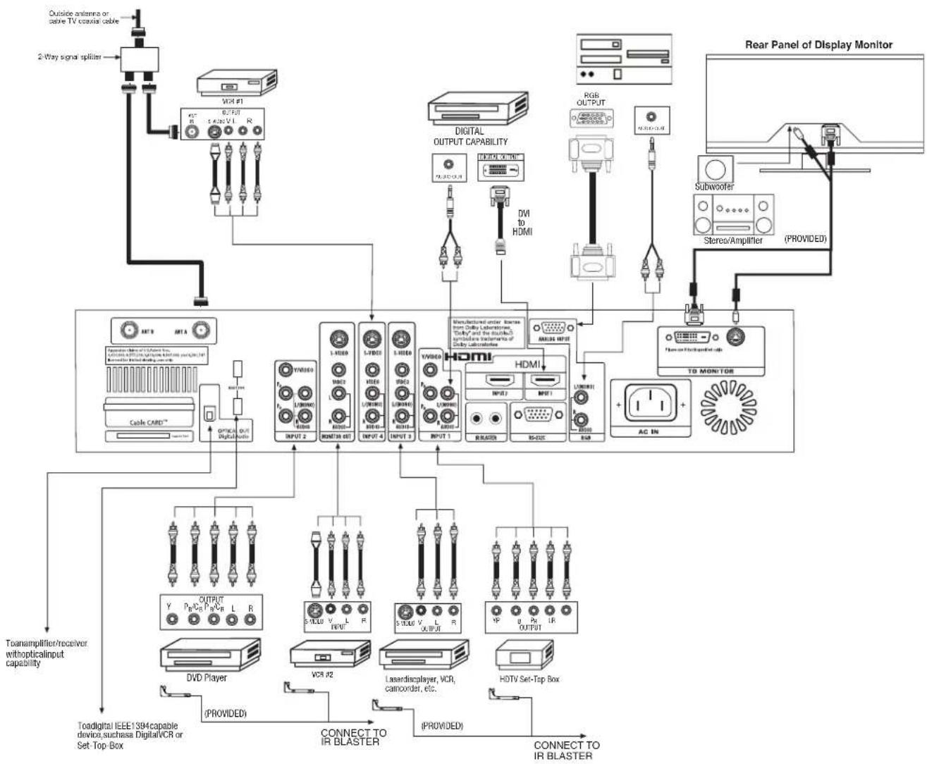
flowchart
graph TD
    A["2-Way signal splitter"] --> B["Outside antennas or cable TV conductor cable"]
    B --> C["VCR #1"]
    C --> D["0.4V/10 R 5.4V/20 V1 R"]
    D --> E["Optical output digital motors"]
    E --> F["Cable CARD™"]
    F --> G["TOANAMPLIFIER/receiver withopticalinput capability"]
    G --> H["To digital IEEE 1984 capable device, such as Digital/VCR or Set-Top Box"]
    H --> I["VCD Player"]
    I --> J["(PROVIDED)"]
    J --> K["CONNECT TO IR BLASTER"]
    K --> L["(PROVIDED)"]
    L --> M["HDTV Set-Top Box"]
    M --> N["HDTV SET-Top Box"]
    N --> O["LED/LED/LED/LED/LED/LED/LED/LED/LED/LED/LED/LED/LED/LED/LED/LED/LED/LED/LED/LED/LED/LED/LED/LED/LED/LED/LED/LED/LED/LED/LED/LED/LED/LED/LED/LED/LED/LED/LED/LED/LED/LED/LED/LED/LED/LED/LED/LED/LED/LED/LED 3"]
    N --> P["Microcontroller unit: from CDMA Laboratories, 'Supply*' and the standard symbols' statements of CDMA laboratories"]
    P --> Q["Microcontroller unit: from CDMA Laboratories, 'Supply*' and the standard symbols' statements of CDMA laboratory"]
    Q --> R["Microcontroller unit: from CDMA Laboratories, 'Supply*' and the standard symbols' statements of CDMA laboratory"]
    R --> S["Microcontroller unit: from CDMA Laboratories, 'Supply*' and the standard symbols' statements of CDMA laboratory"]
    S --> T["Microcontroller unit: from CDMA Laboratories, 'Supply*' and the standard symbols' statements of CDMA laboratory"]
    T --> U["Microcontroller unit: from CDMA Laboratories, 'Supply*' and the standard symbols' statements of CDMA laboratory"]
    U --> V["Microcontroller unit: from CDMA Laboratories, 'Supply*' and the standard symbols' statements of CDMA laboratory"]
    V --> W["Microcontroller unit: from CDMA Laboratories, 'Supply*' and the standard symbols' statements of CDMA laboratory"]
    W --> X["Microcontroller unit: from CDMA Laboratories, 'Supply*' and the standard symbols' statements of CDMA laboratory"]
    X --> Y["Microcontroller unit: from CDMA Laboratories, 'Supply*' and the standard symbols' statements of CDMA laboratory"]
    Y --> Z["Microcontroller unit: from CDMA Laboratories, 'Supply*' and the standard symbols' statements of CDMA laboratory"]
    Z --> AA["Microcontroller unit: from CDMA Laboratories, 'Supply*' and the standard symbols' statements of CDMA laboratory"]
    AA --> AB["Microcontroller unit: from CDMA Laboratories, 'Supply*' and the standard symbols' statements of CDMA laboratory"]
    AB --> AC["Microcontroller unit: from CDMA Laboratories, 'Supply*' and the standard symbols' statements of CDMA laboratory"]
    AC --> AD["Microcontroller unit: from CDMA Laboratories, 'Supply*' and the standard symbols' statements of CDMA laboratory"]
    AD --> AE["Microcontroller unit: from CDMA Laboratories, 'Supply*' and the standard symbols' statements of CDMA laboratory"]
    AE --> AF["Microcontroller unit: from CDMA Laboratories, 'Supply*' and the standard symbols' statements of CDMA laboratory"]
    AF --> AG["Microcontroller unit: from CDMA Laboratories, 'Supply*' and the standard symbols' statements of CDMA laboratory"]
    AG --> AH["Microcontroller unit: from CDMA Laboratories, 'Supply*' and the standard symbols' statements of CDMA laboratory"]
    AH --> AI["Microcontroller unit: from CDMA Laboratories, 'Supply*' and the standard symbols' statements of CDMA laboratory"]
    AI --> AJ["Microcontroller unit: from CDMA Laboratories, 'Supply*' and the standard symbols' statements of CDMA laboratory"]
    AJ --> AK["Microcontroller unit: from CDMA Laboratories, 'Supply*' and the standard symbols' statements of CDMA laboratory"]
    AK --> AL["Microcontroller unit: from CDMA Laboratories, 'Supply*' and the standard symbols' statements of CDMA laboratory"]
    AL --> AM["Microcontroller unit: from CDMA Laboratories, 'Supply*' and the standard symbols' statements of CDMA laboratory"]
    AM --> AN["Microcontroller unit: from CDMA Laboratories, 'Supply*' and the standard symbols' statements of CDMA laboratory"]
    AN --> AO["Microcontroller unit: from CDMA Laboratories, 'Supply*' and the standard symbols' statements of CDMA laboratory"]
    AO --> AP["Microcontroller unit: from CDMA Laboratories, 'Supply*' and the standard symbols' statements of CDMA laboratory"]
    AP --> AQ["Microcontroller unit: from CDMA Laboratories, 'Supply*' and the standard symbols' statements of CDMA laboratory"]
    AQ --> AR["Microcontroller unit: from CDMA Laboratories, 'Supply*' and the standard symbols' statements of CDMA laboratory"]
    AR --> AS["Microcontroller unit: from CDMA Laboratories, 'Supply*' and the standard symbols' statements of CDMA laboratory"]
    AS --> AT["Microcontroller unit: from CDMA Laboratories, 'Supply*' and the standard symbols' statements of CDMA laboratory"]
    AT --> AU["Microcontroller unit: from CDMA Laboratories, 'Supply*' and the standard symbols' statements of CDMA laboratory"]
    AU --> AV["Microcontroller unit: from CDMA Laboratories, 'Supply*' and the standard symbols' statements of CDMA laboratory"]
    AV --> AW["Microcontroller unit: from CDMA Laboratories, 'Supply*' and the standard symbols' statements of CDMA laboratory"]
    AW --> AX["Microcontroller unit: from CDMA Laboratories, 'Supply*' and the standard symbols' statements of CDMA laboratory"]
    AX --> AY["Microcontroller unit: from CDMA Laboratories, 'Supply*' and the standard symbols' statements of CDMA laboratory"]
    AY --> AZ["Microcontroller unit: from CDMA Laboratories, 'Supply*' and the standard symbols' statements of CDMA laboratory"]
NOTE: Cables are optional, except when specified.
- S-VIDEO, YPbPR, IEEE 1394 or HDMI connections are provided for high performance laserdisc players, VCRs etc. that have this feature. Use these connections in place of the standard video connection if your device has this feature.
- If your device has only one audio output (mono sound), connect it to the left audio jack on the AVC Center.
• Refer to the operating guide of your other electronic equipment for additional information on connecting your hook-up cables. - A single VCR can be used for VCR #1 and VCR #2, but note that a VCR cannot record its own video or line output (INPUT: 4 in the example on page 25). Refer to your VCR operating guide for more information on line input-output connections.
- Connect only 1 component (VCR, DVD player, camcorder, etc.) to each input jack.
- COMPONENT: Y-P BPR (Input 1 & 2) connections are provided for high performance components, such as DVD players and set-top-boxes. Use these connections in place of the standard video connection if your device has this feature.
- Your component outputs may be labeled Y, B-Y, and R-Y. In this case, connect the components B-Y output to the TV's P_B input and the components R-Y output to the TV's P_R input.
- Your component outputs may be labeled Y-C B C R . In this case, connect the components C B output to the TV's P B input and the components C R output to the TV's P R input.
- It may be necessary to adjust TINT to obtain optimum picture quality when using the Y-P _B^P R inputs. (See page 54)
- To ensure no copyright infringement, the MONITOR OUT output will be abnormal, when using the Y-P_B^P_R , RGB and HDMI input jacks.
- Input 1 or 2 can accept HDMI signal.
- Input 1 or 2 can accept both component and composite video signal.
- S-VIDEO monitor output may be used for recording only when the input is of S-VIDEO type.
- When using a DVI or HDMI input from a Set-Top-Box, it is recommended to use a 1080i or 720p input signal.
In addition to controlling all the functions on your HITACHI LCD TV, the new remote control is designed to operate different types of VCRs, CATV (Cable TV) converters, set-top-box, satellite receiver, DVD players, and other audio/video equipment with one touch. Basic operation keys are grouped together in one area.
To operate your LCD TV, point the remote control at the remote sensor of the AVC box/Display Monitor and select the TV by pressing the ◀ or ▶ button of the Source Access on the remote. The TV mode indicator will blink, indicating that the remote will now control your television.
To operate your VCR, point the remote at the remote sensor of the VCR and select PVR by pressing the ◀ or ▶ button of the Source Access on the remote. The PVR mode indicator will blink, indicating that the remote will now control your VCR (see page 45 for instructions on how to program the remote to control your VCR).
To operate your PVR (Personal Video Recorder), point the remote at the remote sensor of the PVR and select PVR by pressing the ◀ or ▶ button of the Source Access on the remote. The PVR mode indicator will blink, indicating that the remote will now control your PVR (see page 45 for instruction on how to program the remote to control your PVR).
To operate your cable box, point the remote at the remote sensor of the cable box and select the CABLE (CBL) by pressing the ◀ or ▶ button of the Source Access on the remote. The CBL mode indicator will blink, indicating that the remote will now control your cable box (see page 42 for instructions on how to program the remote to control your cable box).
To operate your set-top-box or satellite receiver point the remote at the remote sensor of the set-top-box and select the SET-TOP-BOX (STB) by pressing the ◀ or ▶ button of the Source Access on the remote. If you have a satellite receiver, use this button to program your satellite receiver. The STB mode indicator will blink, indicating that the remote will now control your set-top-box (see page 43 for instructions on how to program the remote to control your set-top-box).
To operate your DVD player, point the remote at the remote sensor of the DVD player and select DVD by pressing the ◀ or ▶ button of the Source Access on the remote. The DVD mode indicator will blink, indicating that the remote will now control your DVD Player (see page 44 for instruction on how to program the remote to control your DVD player).
To operate additional audio equipment, point the remote at the remote sensor of the component you wish to control and select AMP by pressing the ◀ or ▶ button of the Source Access on the remote. The AMP mode indicator will blink, indicating that the remote will now control your audio equipment (see page 46 for instructions on how to program the remote to control additional Audio/Video equipment).
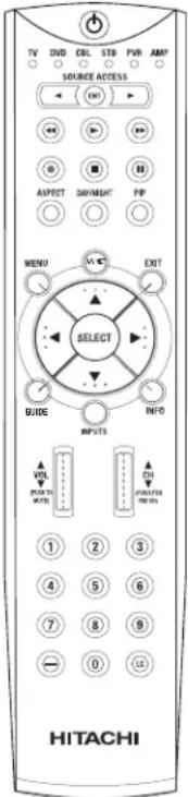
NOTE: When you are in a dark room, press any button on the remote to light up the buttons. The illumination will light for a few seconds during this time and the current mode indicator will flash one time. These buttons will not appear to light if the room is too bright.
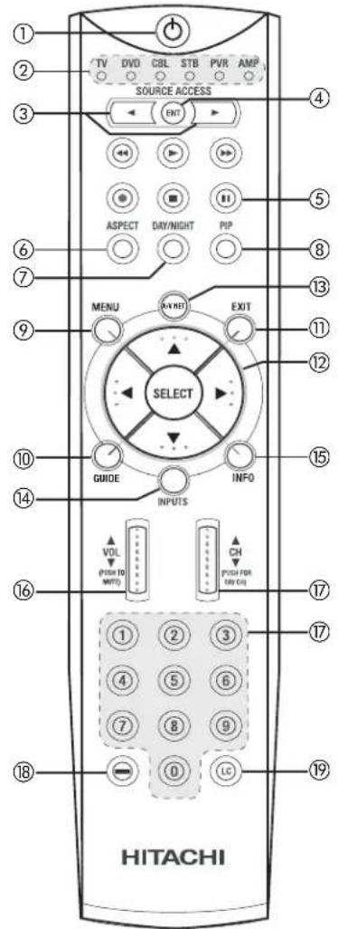
①POWER button
Press this button to turn the TV set on or off when the remote is in TV mode. (See page 27 for instructions on how to set the remote control to TV mode.)
②MODE Indicator
Turns on or blinks to show remote control mode.
③ SOURCE ACCESS (◀, ▶) buttons
Press these buttons to select remote control mode.
④SOURCE ACCESS (ENT) button
Hold down this button while entering your device code to program the remote (see pages 42-49). You can also use this button in an optional Input access feature (see page 47).
⑤ PAUSE button
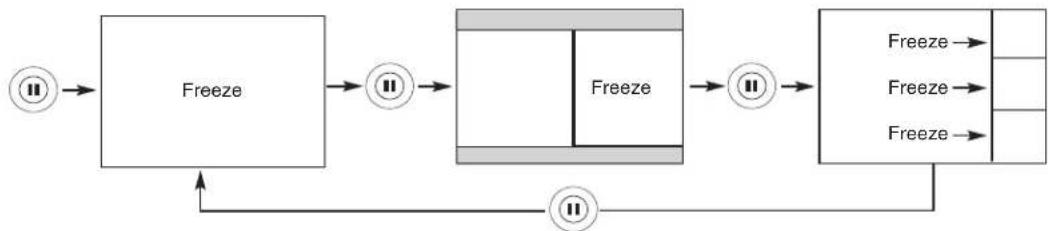
Press the PAUSE button to freeze the picture. Press the EXIT button to return the picture to motion. Press the PAUSE button repeatedly to cycle through the three different freeze modes (see page 41).
flowchart
graph LR
    A["Input"] --> B["Freeze"]
    B --> C["Intermediate"]
    C --> D["Final State"]
    D --> E["Output"]
    B --> F["Feedback Loop"]
    F --> C
    C --> G["Final Output"]
    G --> H["Output"]
⑥ASPECT button
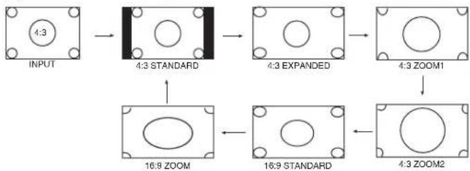
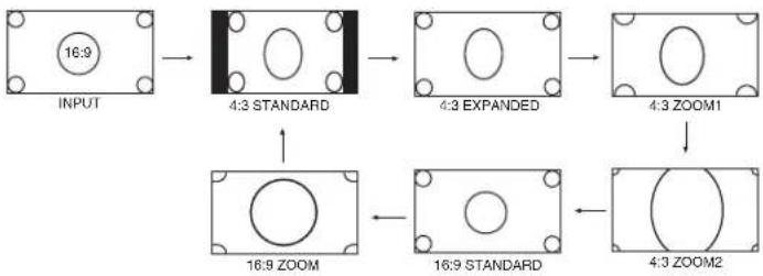
Press this button to quickly change the picture format ASPECT ratio.
Depending on the input signal format received, the picture format ratio allows you to adjust the images through the following options.
4:3 STANDARD Use this aspect mode to display conventional (4:3) images. Side panels (gray areas) are placed to the left and right of the image to preserve the original aspect ratio of the source. Note: Use this mode for only 15% of your total viewing time to prevent uneven aging of the phosphors. Phosphors in the lighted area of the picture will age more rapidly than the gray areas.
4:3 EXPANDED Use this aspect mode to display conventional (4:3) sources by linearly increasing image expansion from the center towards the edges of the display area in order to fill it.
4:3 Zoom1/Zoom2 Use these aspect modes to zoom in on conventional (4:3) sources.
16:9 STANDARD Use this aspect mode to display 16:9 sources like HDTV and DVD's preserving the original 16:9 aspect ratio.
16:9 Zoom Use this aspect to Zoom-in once while in 16:9 aspect.
(1) NTSC/480i/480P Input
flowchart
graph TD
    A["INPUT 4:3"] --> B["4:3 STANDARD"]
    B --> C["4:3 EXPANDED"]
    C --> D["4:3 ZOOM1"]
    D --> E["4:3 ZOOM2"]
    E --> F["16:9 STANDARD"]
    F --> G["16:9 ZOOM"]
(2) 480i/480P Input
flowchart
graph TD
    A["INPUT 16:9"] --> B["4:3 STANDARD"]
    B --> C["4:3 EXPANDED"]
    C --> D["4:3 ZOOM1"]
    D --> E["4:3 ZOOM2"]
    E --> F["16:9 STANDARD"]
    F --> G["16:9 ZOOM"]
(3) 720P/1080i Input

flowchart
graph LR
    A["INPUT 16:9"] --> B["16:9 STANDARD 16:9 ZOOM"]
    B --> C["4:3 EXPANDED"]
(4) RGB (Analog Input) ASPECT DISPLAY MODE.
| RGB (Analog) INPUT SIGNAL | ||||||
| ASPECT MODEAVAILABILITY | Others SVGA/XGA VGA 480p720p1080i | |||||
| X | REAL | REAL | REAL(1) | X | X | |
| NORMAL | NORMAL NORMAL | NORMAL(1) | X | X | ||
| FULL | FULL | FULL | FULL(1) | FULL(2,3) | FULL(2,3) | |
For numbers in ( ), please see corresponding note below.
NOTES: 1. Lack of raster can be seen in RGB (Analog) when a 480p signal is input.
-
AUTO ADJUST function (see page 85) is not available in 720p and 1080i input signal.
-
FULL aspect mode, only 95% of information can be displayed (5% is treated as overscan).
-
Depending on the Aspect selection, Closed Caption display may be missing.
⑦DAY/NIGHT button
Press this button to toggle between Day and Night picture mode settings. Select Day for day time viewing with more brightness and contrast to compete with room light. Select Night for night time viewing with less brightness and contrast for a more detailed picture (see page 51 for settings changes).
NOTE: For automatic DAY/NIGHT picture mode settings, see page 68.
⑧PICTURE-IN-PICTURE button
See separate section on pages 39-41 for a description.
⑨MENU button
The MENU button will start the On-Screen Display.
⑩GUIDE button
Press this button to access the Channel Guide. Press the GUIDE button again to return to normal viewing.
Select CHANNEL GUIDE to display available program information. Only scanned programs that are available at the present time will show in the Channel Guide (see Auto Channel Scan on page 60).
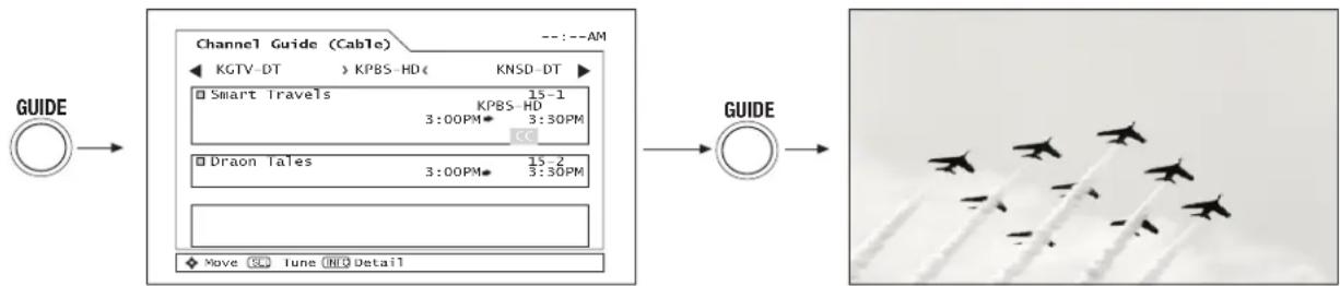
flowchart
graph LR
    A["GUIDE"] --> B["Channel Guide (Cable) --:--AM"]
    B --> C["GUIDE"]
    C --> D["Satellite Sky flying"]
Use the CURSOR PAD ▲, ▼, ◀, ▶ to highlight the channel of choice (example: KPBS-HD).
Press the CURSOR PAD ▲, ▼, to highlight the subchannel of choice (example: 15-1).
Press the SELECT button to tune the subchannel of choice.
NOTE: The availability of Channel Guide Information will depend on the type of Antenna input (Analog, Digital) and Cable subscription.
⑪ EXIT button
This button will exit all On-Screen Displays.
⑫CURSOR PAD/SELECT button
All the On-Screen Display features can be set or adjusted by using the CURSOR PAD, except for numeric entries. The CURSOR PAD will highlight functions or adjust and set different features. Press the CURSOR PAD toward desired direction and press the SELECT button to select.
⑬AV NET button
Press this button to access the Audio/Video network (AV Net) menu. The AV Net allows the user to control external components with the LCD TV's remote control. When you press the AV NET button, the following window will pop up within the Display Monitor screen. The window will disappear after 30 seconds if you don't press any buttons.
Select Device Setup to start.
Use CURSOR PAD ▲, ▼, ◀, ▶ to navigate and SELECT to select button. The command on the button is passed through the IR mouse and onto the AUDIO/VIDEO equipment. These on-screen buttons are called "Soft Keys".
Customize your Audio/Video equipment list and soft keys by selecting the Custom options and following the instructions of the AV NET learning wizard (see page 32).
This window shows the available Audio/Video equipment soft keys. The equipment list will scroll up or down.
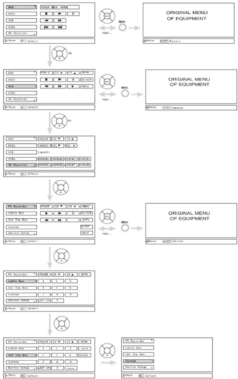
flowchart
graph TD
    A["Original MENU OF EQUIPMENT"] --> B["Menu"]
    B --> C["DOCU"]
    C --> D["Device Setup"]
    D --> E["Device Setup"]
    E --> F["Device Setup"]
    F --> G["Device Setup"]
    G --> H["Device Setup"]
    H --> I["Device Setup"]
    I --> J["Device Setup"]
    J --> K["Device Setup"]
    K --> L["Device Setup"]
    L --> M["Device Setup"]
    M --> N["Device Setup"]
    N --> O["Device Setup"]
    O --> P["Device Setup"]
    P --> Q["Device Setup"]
    Q --> R["Device Setup"]
    R --> S["Device Setup"]
    S --> T["Device Setup"]
    T --> U["Device Setup"]
    U --> V["Device Setup"]
    V --> W["Device Setup"]
    W --> X["Device Setup"]
    X --> Y["Device Setup"]
    Y --> Z["Device Setup"]
    Z --> AA["Device Setup"]
    AA --> AB["Device Setup"]
    AB --> AC["Device Setup"]
    AC --> AD["Device Setup"]
    AD --> AE["Device Setup"]
    AE --> AF["Device Setup"]
    AF --> AG["Device Setup"]
    AG --> AH["Device Setup"]
    AH --> AI["Device Setup"]
    AI --> AJ["Device Setup"]
    AJ --> AK["Device Setup"]
    AK --> AL["Device Setup"]
    AL --> AM["Device Setup"]
    AM --> AN["Device Setup"]
    AN --> AO["Device Setup"]
    AO --> AP["Device Setup"]
    AP --> AQ["Device Setup"]
    AQ --> AR["Device Setup"]
    AR --> AS["Device Setup"]
    AS --> AT["Device Setup"]
    AT --> AU["Device Setup"]
    AU --> AV["Device Setup"]
    AV --> AW["Device Setup"]
    AW --> AX["Device Setup"]
    AX --> AY["Device Setup"]
    AY --> AZ["Device Setup"]
    AZ --> BA["Device Setup"]
    BA --> BB["Device Setup"]
    BB --> BC["Device Setup"]
    BC --> BD["Device Setup"]
    BD --> BE["Device Setup"]
    BE --> BF["Device Setup"]
    BF --> BG["Device Setup"]
    BG --> BH["Device Setup"]
    BH --> BI["Device Setup"]
    BI --> BJ["Device Setup"]
    BJ --> BK["Device Setup"]
    BK --> BL["Device Setup"]
    BL --> BM["Device Setup"]
    BM --> BN["Device Setup"]
    BN --> BO["Device Setup"]
    BO --> BP["Device Setup"]
    BP --> BQ["Device Setup"]
    BQ --> BR["Device Setup"]
    BR --> BS["Device Setup"]
    BS --> BT["Device Setup"]
    BT --> BU["Device Setup"]
    BU --> BV["Device Setup"]
    BV --> BW["Device Setup"]
    BW --> BX["Device Setup"]
    BX --> BY["Device Setup"]
    BY --> BZ["DOCU"]
    BZ --> CA["DOCU"]
    CA --> CB["DVD2"]
    CB --> CC["VCR2"]
    CC --> DD["PV Receiver"]
NOTES: 1. Devices will not be available until Device Setup is completed (see pages 22-24).
- The "Custom" option will not be available until the Custom device Setup is learned and completed. After completion, the "Custom" tag will be replaced with the device tag (see page 32).
- The Custom option only accepts one device at a time. The second Custom device setup will replace the first device.
This function of the AV NET makes it more expandable because it allows the user to use equipment that is not supported by the pre-code library, listed on page 24. For example, after programming your equipment to the AV NET and the soft keys do not work, the user just has to follow the steps below. The AV NET Learning Wizard will transfer any remote button IR code of your equipment to the soft keys of your AV NET. If all remote button transfers are successful, the user can now control their equipment by using the LCD TV remote control.
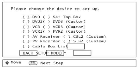
- Press A/V NET button on the remote control.
- Use the CURSOR PAD to select DEVICE SETUP, press the SELECT button.
- Use the CURSOR PAD/SELECT button to choose CUSTOM option (Ex. VCR3).
- Use the CURSOR PAD to select Setup, press the SELECT button.

- Select TV Softkeys to learn, press the SELECT button.
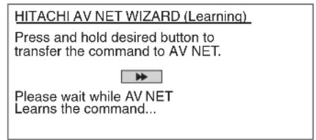
- Press and hold the ▶ button of the VCR remote control while pointing directly at the learning AV NET sensor of the AVC at a distance of 1 to 2 meters.
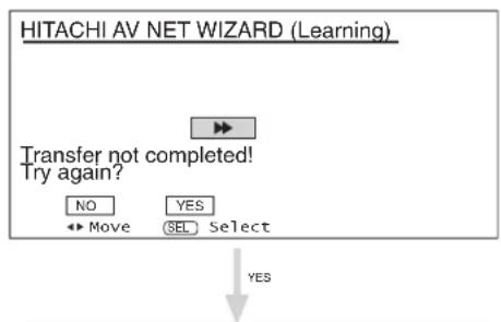
flowchart
graph TD
    A["HITACHI AV NET WIZARD (Learning)"] --> B["Transfer not completed! Try again?"]
    B --> C{NO}
    B --> D{YES}
    C --> E["Move"]
    D --> F["SEL Select"]
    G["→"] --> H["→"]
    I["→"] --> J["→"]
    K["→"] --> L["→"]
    M["→"] --> N["→"]
    O["→"] --> P["→"]
    Q["→"] --> R["→"]
    S["→"] --> T["→"]
    U["→"] --> V["→"]
    W["→"] --> X["→"]
    Y["→"] --> Z["→"]
    AA["→"] --> AB["→"]
    AC["→"] --> AD["→"]
    AE["→"] --> AF["→"]
    AG["→"] --> AH["→"]
    AI["→"] --> AJ["→"]
    AK["→"] --> AL["→"]
    AM["→"] --> AN["→"]
    AO["→"] --> AP["→"]
    AQ["→"] --> AR["→"]
    AS["→"] --> AT["→"]
    AU["→"] --> AV["→"]
    AW["→"] --> AX["→"]
    AY["→"] --> AZ["→"]
- Select OK to continue.
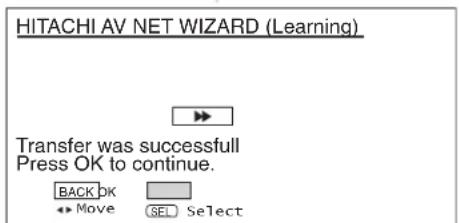
NOTES: 1. It is very important to point the equipment's remote control directly close (about 12 inches) to the LEARNING AV NET sensor of the AVC (see pages 9-10) while trying to transfer the desired remote control button to the AV NET.
2. To access the Menu function of a specific equipment, select the "MENU" soft key on OSD, then press the MENU button of the LCD TV remote control. In order to use CURSOR PAD and EXIT button of the LCD TV remote control, "arrows, select, and EXIT" button must be learned. Then the menu of the programmed equipment can be controlled with the LCD TV remote control.
⑭INPUTS button
When the remote control is in TV mode, press this button to access the INPUTS menu. Use the CURSOR PAD and SELECT button to select the inputs that are being used. Pressing the INPUTS button repeatedly will also cycle through the Inputs menu items. Then press the SELECT button to select.
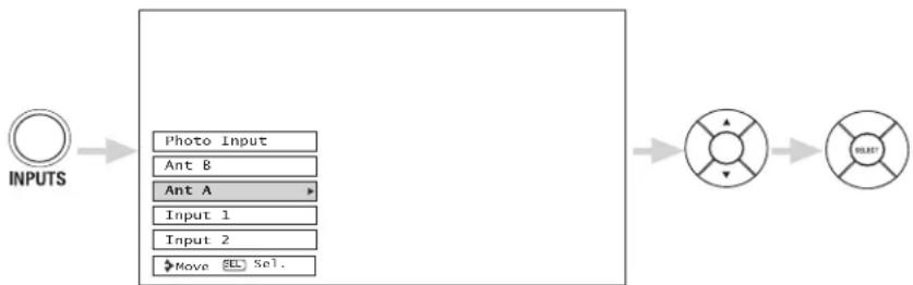
flowchart
graph LR
    A["INPUTS"] --> B["Photo Input"]
    B --> C["Ant B"]
    C --> D["Ant A"]
    D --> E["Input 1"]
    E --> F["Input 2"]
    F --> G["Move SEL Sel."]
    G --> H["OUTPUT"]
    H --> I["SIGHT"]
Photo Input
Ant B
Ant A
Input 1
Input 2
Input 3
Input 4
Input 5
RGB
IEEE 1394
Select to access your pictures from a digital camera connected to the Photo Input in the front panel of the AVC (see page 34).
Select to choose Antenna B.
Select to choose Antenna A.
Select to choose Input 1 for Video 1.
Select to choose Input 2 for Video 2.
Select to choose Input 3 for Video 3.
Select to choose Input 4 for Video 4.
Select to choose Input 5 for Video 5.
Select to choose for RGB input (see pages 78-87).
Select to choose for IEEE 1394 Input (see page 36).
PHOTO INPUT
This feature is useful for viewing digital still pictures from your digital camera using the Photo Input in the front panel of the AVC.
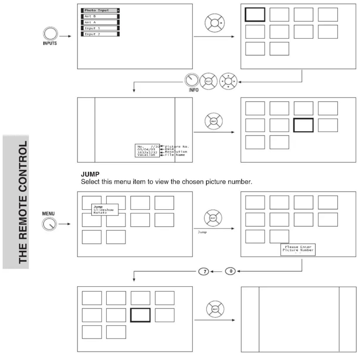
flowchart
graph TD
    A["INPUTS"] --> B["Photo Input"]
    B --> C["Ant B"]
    B --> D["Ant A"]
    B --> E["Input 1"]
    B --> F["Input 2"]
    G["INFO"] --> H["Menu with No. 7/10, Date, Vacation, File Name"]
    H --> I["Jump Slideshow Rotate"]
    I --> J["Jump"]
    J --> K["Please Enter Picture Number"]
    K --> L["Menu with 7, 0, 7"]
    L --> M["Menu with Jump"]
    M --> N["Menu with 0, 0, 0, 0, 0, 0, 0, 0, 0, 0, 0, 0, 0, 0, 0, 0, 0, 0, 0, 0, 0, 0, 0, 0, 0, 0, 0, 0, 0, 0, 0, 0"]
NOTES: 1. The maximum number of digital Photos that can be displayed is 999.
2. Press INFO button to show Picture Numbers in Thumbnail view, plus other information in individual photos.
3. Digital photos recorded on a DVD-RAM disc may not work with this Photo Input.
4. Certain types of digital cameras may not work with this Photo Input.
5. Digital cameras with low battery power may not properly display your photos in this input.
6. The screen may show "Input device not detected" if the digital camera's large capacity memory is fully loaded. Please wait 1 or 2 minutes before checking your Photo Input connections.
7. The screen may show "Input device not detected" due to slow access time on some digital cameras. Please wait 1 or 2 minutes before checking your Photo Input connections.
NOTES: 1. The maximum number of digital Photos that can be displayed is 999.
-
Press INFO button to show Picture Numbers in Thumbnail view, plus other information in individual photos.
-
Digital photos recorded on a DVD-RAM disc may not work with this Photo Input.
-
Certain types of digital cameras may not work with this Photo Input.
-
Digital cameras with low battery power may not properly display your photos in this input.
-
The screen may show "Input device not detected" if the digital camera's large capacity memory is fully loaded. Please wait 1 or 2 minutes before checking your Photo Input connections.
-
The screen may show "Input device not detected" due to slow access time on some digital cameras. Please wait 1 or 2 minutes before checking your Photo Input connections.
SLIDESHOW
Select this menu item to start a slideshow of the Photos in the Digital Camera. Time interval selections can be set from 5, 10 and 30 seconds.
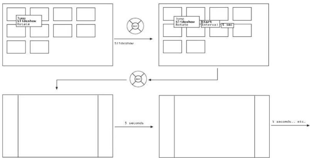
flowchart
graph TD
    A["Jump Slideshow Rotate"] --> B["Slideshow"]
    B --> C["Jump slideshow Rotate"]
    C --> D["Start Interval 5 sec"]
    D --> E["5 seconds... etc."]
    E --> F["5 seconds"]
    F --> G["Next Step"]
    G --> H["Next Step"]
    H --> I["Next Step"]
    I --> J["Next Step"]
    J --> K["Next Step"]
    K --> L["Next Step"]
    L --> M["Next Step"]
    M --> N["Next Step"]
    N --> O["Next Step"]
    O --> P["Next Step"]
    P --> Q["Next Step"]
    Q --> R["Next Step"]
    R --> S["Next Step"]
    S --> T["Next Step"]
    T --> U["Next Step"]
    U --> V["Next Step"]
    V --> W["Next Step"]
    W --> X["Next Step"]
    X --> Y["Next Step"]
    Y --> Z["Next Step"]
    Z --> A
Use CURSOR PAD ▲, ▼ to highlight Slideshow item.
While interval is highlighted, press SELECT to change interval time from 5, 10 and 30 seconds. Each press will change interval time from the three mentioned choices.
Press SELECT to stop on a chosen picture of the slideshow. After 30 seconds, the slideshow will resume, or press SELECT again to continue the slideshow.
Press EXIT to exit the slideshow.
ROTATE
Select this menu item to rotate selected photos either clockwise (CURSOR PAD ▶) and counterclockwise (CURSOR PAD ◀). Rotate menu item is also available in THUMBNAIL view.
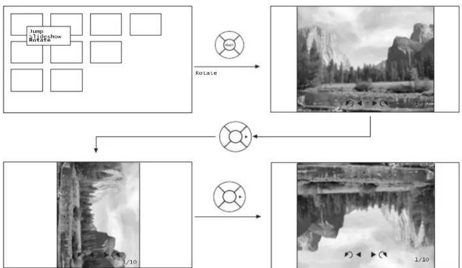
flowchart
graph TD
    A["Jump slideshow Rotate"] --> B["Rotate"]
    B --> C["Video Player"]
    C --> D["1/10"]
    D --> E["Video Player"]
    E --> F["1/10"]
NOTES:
- Photo file names modified on a computer should be 8 characters (Ex. ABCD1234.jpg). 1st character: letters; 2nd to 4th: letters or numbers; 5th to 8th: numbers. Photo files should be first placed on a sub directory name with 8 characters (Ex. 123ABCDE). 1st to 3rd: number; 4th to 8th: letters. The sub directory then should be placed on a main directory with a "dcim" file name format.
- Supported image types are up to 3072 x 2304; JPEG format should conform with DCF Standard (Design rule for Camera File System).
- This TV set displays only digital pictures from digital cameras which meet DCF Standard. Pictures that were copied, edited or modified on a computer may not be displayed on the TV set.
IEEE1394 Use this function to control your devices with digital interface capability. Press the INPUTS button, CURSOR PAD and SELECT button to select IEEE 1394.
(When an IEEE1394 device is not connected)
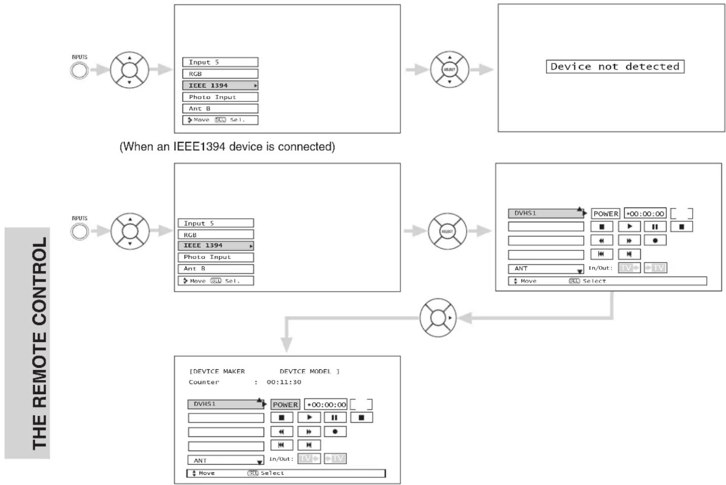
flowchart
graph TD
    A["INPUTS"] --> B["Input 5 RGB IEEE 1394 Photo Input Ant B Move Sel."]
    B --> C["SELECT"]
    C --> D["Device not detected"]
    E["INPUTS"] --> F["Input 5 RGB IEEE 1394 Photo Input Ant B Move Sel."]
    F --> G["SELECT"]
    G --> H["DVHS1 POWER *00:00:00 [■"][◀] ▶ II ■]
    H --> I["Select"]
    I --> J["ANT In/Out: TV+ -TV"]
    J --> K["Move Sel. Select"]
    K --> L["DEVICE MAKER DEVICE MODEL Counter : 00:11:30 DVHS1 POWER *00:00:00 [■"][◀] ▶ II ■]
    L --> M["In/Out: IV+ -IV ▶ Move Sel. Select"]
Use CURSOR PAD▲, ▼ to highlight connected device (example D-VHS1).
Use CURSOR PAD ▶ to select connected device (example D-VHS1).
Use CURSOR PAD cursors to highlight POWER.
Press the SELECT button to power on the device.
Use CURSOR PAD cursors to select D-VHS operation.
Press down on the CURSOR PAD to enable the selected operation.
Use CURSOR PAD cursors to highlight the TV IN/OUT operation.
Press down on CURSOR PAD to select: TV IN is DVHS
TV OUT is ANT A
NOTES:
- The digital device will be automatically recognized if properly connected.
- Four (4) IEEE1394 devices can be listed on the menu, but only 1 device at a time can be used. If a fifth device is connected, it will replace the first device on the menu list.
- This TV's IEEE1394 connection is not compatible with a DV camcorder (Digital Video Camcorder) or a PC.
- The On-Screen-Display will not disappear until the EXIT button is pressed.
- Not all devices with IEEE1394 capability are compatible with this TV. Any compatibility problems with other manufacturers devices should be brought to the attention of those manufacturers.
- TV IN/OUT functions are not available when DVHS is in playback or recording.
⑮INFO button
Press this button when you want to check the channel being received, the picture source, if the channel has stereo (ST) or second audio program (SAP), the time, CHANNEL ID and if the TIMER is set.
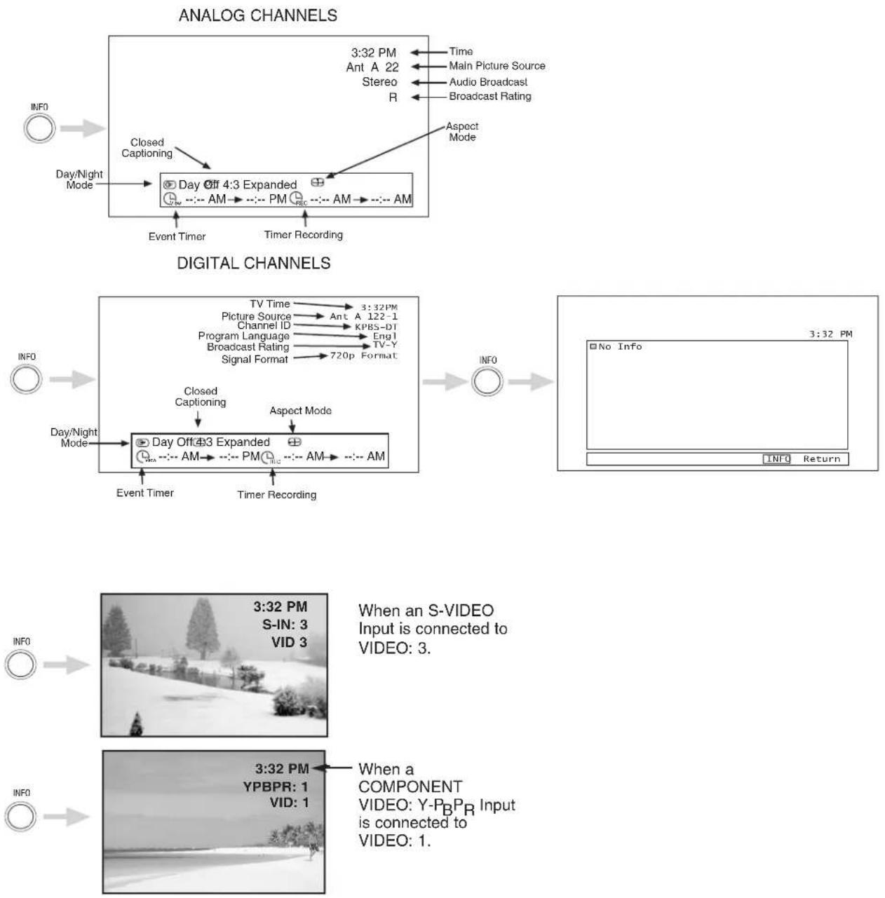
NOTES: 1. The Sleep Timer info will show momentarily after releasing INFO button.
2. Press the INFO button again or the EXIT button to return to normal viewing.
⑯VOLUME (VOL) WHEEL, MUTE button
Use the VOL WHEEL (▲ or ▼) until you obtain the desired sound level.
To reduce the sound to one half of normal volume (SOFT MUTE) to answer the telephone, etc., press the VOL wheel down. Press the VOL wheel again to turn the sound off completely (MUTE). To restore the sound, press the VOL wheel one more time, or VOL Up (▲).

flowchart
graph LR
    A["Volume 8"] --> B["VOL (FUSH TO WRITE)"]
    B --> C["Soft Mute 8"]
    C --> D["VOL (FUSH TO WRITE)"]
    D --> E["Mute 8"]
Closed Captioning will display automatically when MUTE/SOFT MUTE is on and Closed Caption is set to AUTO (see page 75).
When the TV power is turned off at a volume level 31 or greater, the volume level will default to 30 when the TV is turned on. However, if it is set to a level 30 or less, the volume level will be at the level it was set when the TV is turned ON.
⑰CHANNEL (CH) WHEEL/CHANNEL SELECTOR buttons
The CHANNEL wheel or the CHANNEL SELECTOR buttons are used to select channels, lock access code, etc. Use the CHANNEL WHEEL (▲ or ▼) to select the desired channel. Use the CHANNEL SELECTOR buttons to enter one, two, or three numbers to select channels. Enter "0" first for channels 1 to 9, or simply press the single digit channel you wish to tune then wait a few seconds for the TV to tune. For Digital Channels, use the CHANNEL SELECTOR buttons with the (-) DASH button. Channel selection may also be performed by CHANNEL WHEEL up (▲) or CHANNEL WHEEL down (▼).
Press the channel (CH) wheel to switch to Favorite (FAV) channel mode. You will know you are in Favorite Channel mode when (FAV) is displayed and the displayed channel is GREEN. Press it again to return to your regular tuned channels. You can add any channel to your Favorite channel list by pressing and holding down the Channel (CH) wheel until the displayed channel turns from WHITE to highlighted GREEN. You can also delete a channel from your favorite channel list by pressing and holding down the Channel (CH) wheel until the displayed channel turns highlighted GREEN to WHITE.

flowchart
graph LR
    A["Ant A 22 FAV Ant A 22"] --> B["Sensor: CH, Pulse Force: 150 Ω"]
    B --> C["Sensor: CH, Pulse Force: 150 Ω"]
    C --> D["Ant A 22"]
⑱(-) DASH button
Use the (-) DASH button with the CHANNEL SELECTOR buttons to enter Digital Channels that have subchannel numbers indicated by (-) DASH (example 15-1).
⑲LAST CHANNEL (LC) button
Press this button to toggle between the current and last channel viewed.
Your HITACHI LCD TV incorporates Two Tuner technology designed for improved viewing enjoyment. This Two Tuner feature allows you to view antenna inputs on both the main picture and sub-picture simultaneously, with separate tuning control for each.
ANT A input can be viewed as both the main picture and the sub-picture simultaneously. ANT B can only be viewed as a main picture. To select between main picture and PIP sub-picture tuning, use the CURSOR PAD on the remote. The green highlighted channel display will move with every press of the CURSOR PAD (◀, ▶).
The Picture-in-Picture feature is convenient when you want to watch more than one program at the same time. You can watch a TV program while viewing other programs from any of the video inputs.
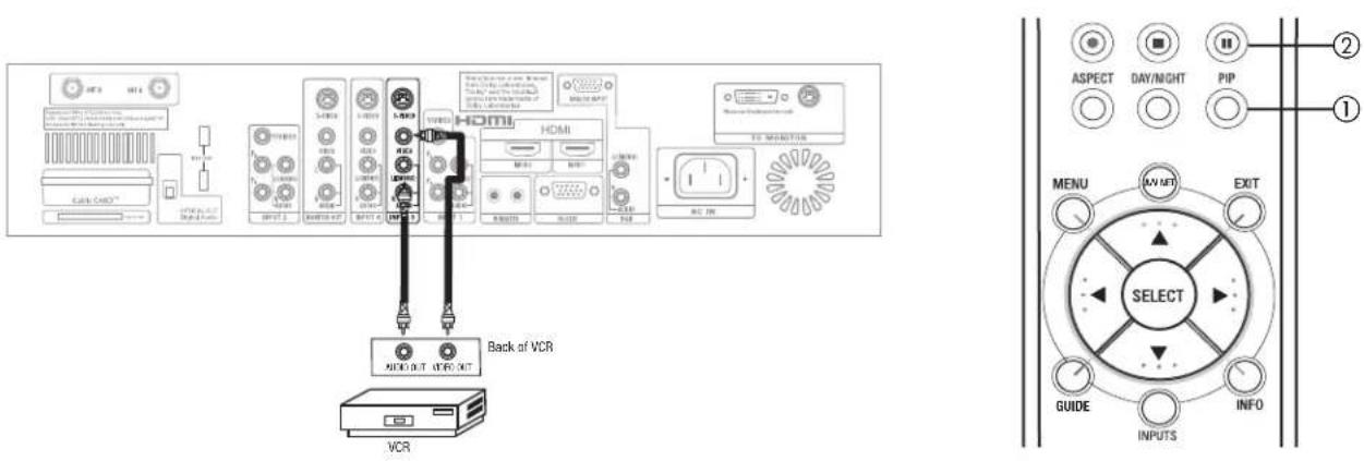
Use above connection to view VCR program as a sub-picture while viewing another program as main picture (ANT A, ANT B, INPUT:1, INPUT:2, INPUT:4, or INPUT:5). You may also view the VCR program as a main picture while viewing another program as a sub-picture (ANT A, INPUT:1, INPUT:2, INPUT:4 or INPUT:5).
When installing a CableCARD, connect your coaxial cable to ANT A (see page 13). ANT B will not be available while using a CableCARD.
① PIP button
Press the PIP button and a sub-picture will appear in one of the four different modes (POP, PIP, SPLIT or SURF), depending on the INPUT signal. To change the PIP mode, use the PIP button to cycle through the four different modes.
POP MODE PICTURE-IN-PICTURE
POP Mode PIP displays the sub-picture outside of the main picture. Use the CURSOR PAD (▲, ▼) to move the sub-picture. This feature is not available with a 1080i component input or Digital signal. Please refer to the PICTURE-IN-PICTURE MODES Table (see page 40).
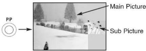
NOTES: 1. Digital Channels cannot be viewed as a sub-picture.
- PIP MODE Picture-in-Picture is only available with a 1080i component or digital signal.
- Press the CURSOR PAD (◀, ▶) to enable the sub-picture sound.
- Sub-picture channel availability depends on the channel list.
PIP MODE PICTURE-IN-PICTURE
This feature is only available with a 1080i component input or Digital signal. To prevent a pattern burn, occasionally move the sub-picture using the CURSOR PAD.
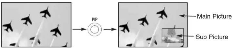
SPLIT MODE PICTURE-IN-PICTURE
Split Mode PIP displays the main picture and sub-picture evenly on the screen.
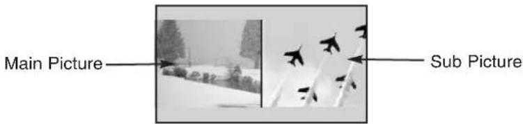
SURF MODE PICTURE-IN-PICTURE
Surf Mode PIP automatically scans all active channels (those set in memory) and displays them as PIP Pictures or Thumbnail channels.
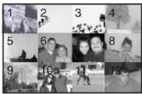
NOTE: Selecting individual sub-pictures while in Surf mode is not available.
PICTURE-IN-PICTURE (PIP) MODES
| PIP Mode | Sub Main | NTSC | 480i | 480p | 720p | 1080i |
| POP | NTSC Yes Yes -- Yes | |||||
| 480i Yes Yes -- Yes | ||||||
| PIP 4x3 | 1080i Yes Yes --- | |||||
| PIP 16x9 | 1080i Yes Yes -- Yes | |||||
| SPLIT | NTSC Yes Yes Yes Yes Yes Yes | |||||
| 480i Yes Yes Yes Yes | ||||||
| 480p Yes Yes Yes Yes | ||||||
| 720p Yes Yes Yes Yes | ||||||
| 1080i Yes Yes Yes Yes | ||||||
| 12 Pix | - Ant A/B -- | - | - | |||
② PAUSE button
If you wish to freeze the sub-picture, press the PAUSE button. This is convenient when trying to write down the address for a mail order company, recording statistics for a sporting event, etc. To return the picture to motion, press the EXIT button. Press the PAUSE button repeatedly to toggle between FREEZE modes (Main Freeze, SPLIT and STROBE).
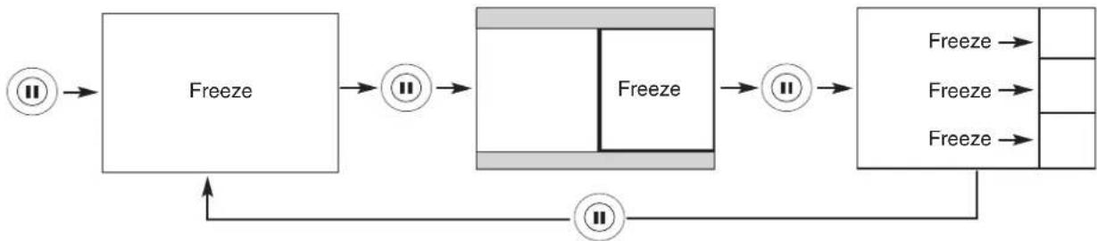
flowchart
graph LR
    A["<<"] --> B["Freeze"]
    B --> C["<<"] --> D["Freeze"]
    D --> E["<<"] --> F["Freeze"]
    F --> G["<<"] --> H["Freeze"]
    H --> I["<<"] --> J["Freeze"]
    J --> K["<<"] --> L["Freeze"]
    L --> M["<<"] --> N["Freeze"]
    N --> O["<<"] --> P["Freeze"]
    P --> Q["<<"] --> R["Freeze"]
    R --> S["<<"] --> T["Freeze"]
    T --> U["<<"] --> V["Freeze"]
    V --> W["<<"] --> X["Freeze"]
    X --> Y["<<"] --> Z["Freeze"]
    Z --> AA["<<"] --> AB["Freeze"]
    AB --> AC["<<"] --> AD["Freeze"]
    AD --> AE["<<"] --> AF["Freeze"]
    AF --> AG["<<"] --> AH["Freeze"]
    AH --> AI["<<"] --> AJ["Freeze"]
    AJ --> AK["<<"] --> AL["Freeze"]
    AL --> AM["<<"] --> AN["Freeze"]
    AN --> AO["<<"] --> AP["Freeze"]
    AP --> AQ["<<"] --> AR["Freeze"]
    AR --> AS["<<"] --> AT["Freeze"]
    AT --> AU["<<"] --> AV["Freeze"]
    AV --> AW["<<"] --> AX["Freeze"]
    AX --> AY["<<"] --> AZ["Freeze"]
    AZ --> BA["<<"] --> BB["Freeze"]
    BB --> BC["<<"] --> BD["Freeze"]
    BD --> BE["<<"] --> BF["Freeze"]
    BF --> BG["<<"] --> BH["Freeze"]
    BH --> BI["<<"] --> BJ["Freeze"]
    BJ --> BK["<<"] --> BL["Freeze"]
    BL --> BM["<<"] --> BN["Freeze"]
    BN --> BO["<<"] --> BP["Freeze"]
    BP --> BQ["<<"] --> BR["Freeze"]
    BR --> BS["<<"] --> BT["Freeze"]
    BT --> BU["<<"] --> BV["Freeze"]
    BV --> BW["<<"] --> BX["Freeze"]
    BX --> BY["<<"] --> BZ["Freeze"]
    BZ --> CA["<<"] --> CB["Freeze"]
    CB --> CC["<<"] --> CD["Freeze"]
    CD --> CE["<<"] --> CF["Freeze"]
    CF --> CG["<<"] --> CH["Freeze"]
    CH --> CI["<<"] --> CJ["Freeze"]
    CJ --> CK["<<"] --> CR["Freeze"]
    CR --> CS["<<"] --> CT["Freeze"]
    CT --> CU["<<"] --> CV["Freeze"]
    CV --> CW["<<"] --> CX["Freeze"]
    CX --> CY["<<"] --> CZ["Freeze"]
    CZ --> DA["<<"] --> DB["Freeze"]
    DB --> DC["<<"] --> DV["Freeze"]
    DV --> DW["<<"] --> DX["Freeze"]
    DX --> DBD["<<"] --> DXB["Freeze"]
MAIN FREEZE
Press the PAUSE button to freeze one frame of the picture you are currently viewing and the frozen frame will show in the Main Picture. Press the EXIT button to return to normal viewing. This feature is useful for freezing a picture frame with addresses.
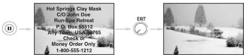
SPLIT FREEZE
Press the PAUSE button to freeze the picture you are currently viewing (only the right sub-picture will freeze). Press the EXIT button to return to normal viewing.
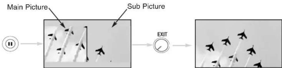
flowchart
graph LR
    A["Main Picture"] --> B["Sub Picture"]
    B --> C["EXIT"]
STROBE FREEZE
Press the PAUSE button to freeze three frames of the picture you are currently viewing (only the 3 sub-pictures will freeze). Press the EXIT button to return to normal viewing. This feature is useful for viewing a moving picture that has many details, for example, a close play in a sporting event or a golf swing.
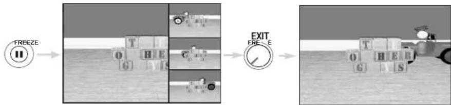
flowchart
graph LR
    A["FREEZE"] --> B["T block"]
    B --> C["G block"]
    C --> D["H block"]
    D --> E["S block"]
    E --> F["E EXIT"]
    F --> G["FREE"]
    G --> H["Tractor with blocks T, G, H, S"]
NOTES: 1. The default FREEZE mode is the MAIN freeze followed by the SPLIT freeze and then the STROBE freeze. The last Freeze mode you selected before you pressed the EXIT button will be the one that comes up after pressing the PAUSE button again.
- Each freeze frame in Strobe Freeze is delayed about 0.1 (1/10) second.
- Strobe Freeze is not available in 480p/720p/1080i inputs.
Operating the precoded function for your cable box.
This remote is designed to operate different types of cable boxes. You must first program the remote to match the remote system of your cable box (refer to pages 48-49 for pre-codes).
-
Turn ON your cable box.
-
Aim the remote control at the front of your cable box.
-
To switch to Cable (CBL) pre-coded mode, use the SOURCE ACCESS buttons (◀, ▶) on the remote control to position the LED light to the corresponding selection.
-
Hold down the ENT button on the remote and enter the four digit preset code that matches your cable box as shown on pages 48-49. Release the ENT button. The indicator light will flash 3 times if the code was accepted.
-
Aim the remote at the cable box and press the POWER button. The remote will turn off your cable box when the correct four digit preset code is entered. When this occurs, the remote control is programmed for your cable box. If the cable box does not turn off, try a different four digit preset code.
-
The remote will now control your Cable box.
NOTES:
- If your cable box cannot be operated after performing the above procedures, your cable box code has not been precoded into the remote.
- In the unlikely event that your cable box cannot be operated after performing the above procedures, please consult your cable box operating guide.
- The remote control will remember the codes you have programmed until the batteries are removed from the remote control. After replacing the batteries repeat the entire programming procedure as stated above.
①PRECODED CABLE BOX buttons
These buttons transmit the chosen precoded cable codes.
②EXCLUSIVE TV buttons
These buttons are for operating the TV.
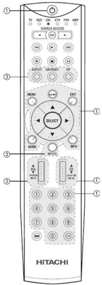
MY CABLE BOX CODE IS: ____
NOTE: Refer to instruction manual of the Cable Box for operation of the buttons exclusively for the Cable Box.
Operating the precoded function for your set-top-box/satellite receiver.
This remote is designed to operate different types of set-top-box/satellite systems. You must first program the remote to match the remote system of your set-top-box/satellite systems (refer to pages 48-49 for pre-codes).
-
Turn ON your set-top-box/satellite systems.
-
Aim the remote control at the front of your set-top-box/satellite systems.
-
To switch to set-top-box/satellite (STB) pre-coded mode, use the SOURCE ACCESS buttons (◀, ▶) on the remote control to position the LED light to the corresponding selection.
-
Hold down the ENT button on the remote and enter the four digit preset code that matches your set-top-box/satellite receiver as shown on page 48-49. Release the ENT button. The indicator light will flash 3 times if the code was accepted.
-
Aim the remote at the set-top-box/satellite receiver and press the POWER button. The remote will turn off your set-top-box/satellite receiver when the correct four digit preset code is entered. When this occurs, the remote control is programmed for your set-top-box/satellite receiver. If the set-top-box/satellite receiver does not turn off, try a different four digit preset code.
-
The remote will now control your set-top-box/satellite receiver.
NOTES:
-
If your set-top-box/satellite receiver cannot be operated after performing the above procedures, your set-top-box/satellite receiver code has not been precoded into the remote.
-
In the unlikely event that your set-top-box/satellite receiver cannot be operated after performing the above procedures, please consult your set-top-box/satellite receiver operating guide.
-
The remote control will remember the codes you have programmed until the batteries are removed from the remote control. After replacing the batteries repeat the entire programming procedure as stated above.
①PRE-CODED SET-TOP-BOX/SATELLITE RECEIVER buttons
These buttons transmit the chosen pre-coded set-top-box/satellite codes.
② EXCLUSIVE TV buttons
These buttons are for operating the TV.
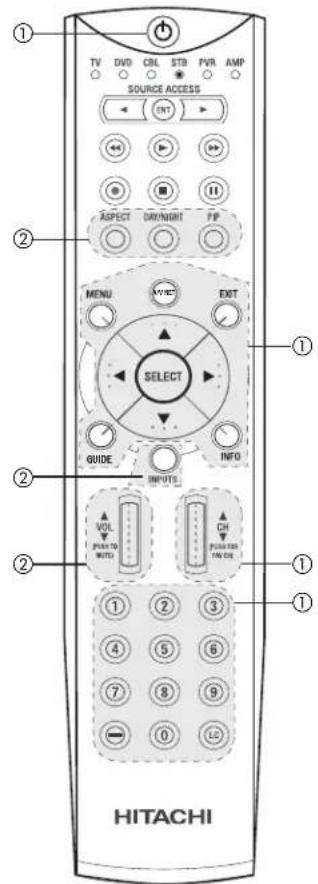
MY SATELLITE RECEIVER/STB CODE IS:
NOTE: Refer to instruction manual of the set-top-box/satellite receiver for operation of the buttons exclusively for the set-top-box/satellite receiver.
Operating the precoded function for your DVD player.
This remote is designed to operate different types of DVD players. You must first program the remote to match the remote system of your DVD player (refer to pages 48-49 for pre-codes).
- Turn ON your DVD player.
- Aim the remote control at the front of your DVD player.
- To switch to DVD pre-coded mode, use the SOURCE ACCESS buttons (◀, ▶) on the remote control to position the LED light to the corresponding selection.
- Hold down the ENT button on the remote and enter the four digit preset code that matches your DVD player, as shown on pages 48-49. Release the ENT button. The indicator light will flash 3 times if the code was accepted.
- Aim the remote at the DVD player and press the POWER button. The remote will turn off your DVD player when the correct four digit preset code is entered. When this occurs, the remote control is programmed for your DVD player. If the DVD player does not turn off, try a different four digit preset code.
- The remote will now control your DVD player.
- You will need to set the display type of your DVD player to 16:9 widescreen.
NOTES:
- If your DVD player cannot be operated after performing the above procedures, your DVD player's code has not been precoded into the remote.
- In the unlikely event that your DVD player cannot be operated after performing the above procedures, please consult your DVD player operating guide.
- The remote control will remember the codes you have programmed until the batteries are removed from the remote control. After replacing the batteries repeat the entire programming procedure as stated above.
①PRECODED DVD Buttons
These buttons transmit the chosen precoded DVD codes.
② EXCLUSIVE TV Buttons
These buttons are for operating the TV.
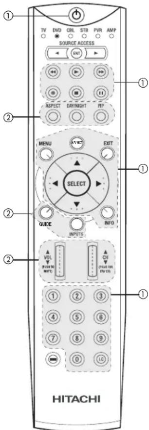
NOTE: Refer to instruction manual of the DVD player for operation of the buttons exclusively for the DVD player.
Operating the precoded function for your VCR/PVR (Personal Video Recorder).
This remote is designed to operate different types of VCRs/PVRs. You must first program the remote to match the remote system of your VCR/PVR (refer to pages 48-49 for pre-codes).
- Turn ON your VCR/PVR.
- Aim the remote control at the front of your VCR/PVR.
- To switch to VCR/PVR pre-coded mode, use the SOURCE ACCESS buttons (◀, ▶) on the remote control to position the LED light to the corresponding selection.
- Hold down the ENT button on the remote and enter the four digit preset code that matches your VCR/PVR, as shown on pages 48-49. Release the ENT button. The indicator light will flash 3 times if the code was accepted.
- Aim the remote at the VCR/PVR and press the POWER button. The remote will turn off your PVR when the correct four digit preset code is entered. When this occurs, the remote control is programmed for your VCR/PVR. If the VCR/PVR does not turn off, try a different four digit preset code.
- The remote will now control your VCR/PVR.
NOTES:
- If your PVR cannot be operated after performing the above procedures, your PVR's code has not been precoded into the remote.
- In the unlikely event that your PVR cannot be operated after performing the above procedures, please consult your PVR operating guide.
- The remote control will remember the codes you have programmed until the batteries are removed from the remote control. After replacing the batteries repeat the entire programming procedure as stated above.
- VCR precode library is included in the PVR mode. Default device for this mode is Hitachi VCR.
- INFO, GUIDE and LC (Last Channel) buttons are for PVR devices, not for VCR.
①PRECODED VCR/PVR Buttons
These buttons transmit the chosen precoded VCR/PVR codes.
② EXCLUSIVE TV Buttons
These buttons are for operating the TV.
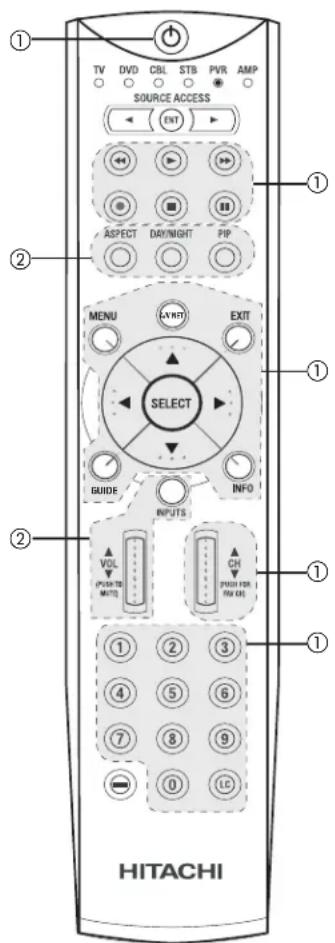
NOTE: Refer to instruction manual of the VCR/PVR for operation of the buttons exclusively for the VCR/PVR.
Operating the precoded function for your Audio component.
This remote is designed to operate different types of Audio component. You must first program the remote to match the remote system of your Audio component (refer to pages 48-49 for pre-codes).
- Turn ON your Audio component you wish to control with the Remote.
- Aim the remote control at the front of your Audio component.
- To switch to Audio (AMP) component pre-coded mode, use the SOURCE ACCESS buttons (◀, ▶) on the remote control to position the LED light to the corresponding selection.
- Hold down the ENT button on the remote and enter the four digit preset code that matches your Audio component, as shown on pages 48-49. Release the ENT button. The indicator light will flash 3 times if the code was accepted.
- Aim the remote at the Audio component and press the POWER button. The remote will turn off your Audio component when the correct four digit preset code is entered. When this occurs, the remote control is programmed for your Audio component. If the Audio component does not turn off, try a different four digit preset code.
- The remote will now control your Audio component.
- Repeat steps 1 - 6 if you wish to program the remote to control another Audio component.
NOTES:
- If your Audio component cannot be operated after performing the above procedures, your Audio component's code has not been precoded into the remote.
- In the unlikely event that your Audio component cannot be operated after performing the above procedures, please consult your Audio equipment operating guide.
- The remote control will remember the codes you have programmed until the batteries are removed from the remote control. After replacing the batteries repeat the entire programming procedure as stated above.
- CD precode library is included in the AMP mode. Default device for this mode is Hitachi Audio/Video Receiver (AVR/AMP).
- INPUT, GUIDE, Channel (up/down), Volume (up/down) and REC button are not for CD devices.
①PRECODED AUDIO Buttons
These buttons transmit the chosen precoded Audio component codes.
② EXCLUSIVE TV Buttons
These buttons are for operating the TV.
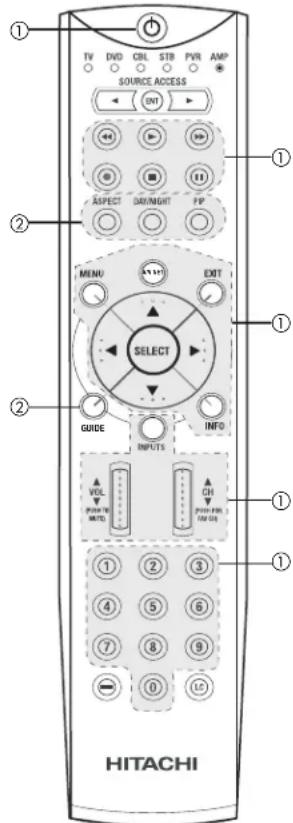
MY AUDIO EQUIPMENT CODE IS:
CD
AMP/RCVR
NOTES: 1. The REC (Record) button only applies to some precoded amplifier/receiver codes.
- Refer to instruction manual of the Audio equipment for operation of the buttons exclusively for the Audio equipment.
INPUT ACCESS
This optional feature allows the user of the remote control to setup it's ENTER (ENT) button to access the specified input of the TV. Setup for this feature is applicable to the remote control's normal mode only and only applies to the DVD, CBL, STB, PVR and AMP modes.
- Select the desired device mode (DVD, CBL, STB, PVR, or AMP) by using your SOURCE ACCESS buttons (◀, ▶) to position the LED indicator to the corresponding selection.
- Hold down the ENTER (ENT) button on the remote and enter the four digit preset code that matches your device as shown on pages 48-49.
- Then enter the assigned input number (1-5) that the device is related to.
- Release ENTER (ENT) button.
- If done correctly, the device LED indicator will flash 3 times to confirm proper setup.
- The remote will now control the desired device.
- Pressing the ENTER (ENT) button will now access the video input (1-5) of the desired device.
SETUP EXAMPLE (Hitachi DVD with precode 0573 connected to INPUT 1 of the TV)
① Select DVD mode by using your SOURCE ACCESS buttons (◀, ▶) to position the LED indicator to DVD.
② Hold down the ENTER (ENT) button and press the numbers 0, 5, 7 and 3.
③ Then press the number 1 for the assigned input number of the DVD player.
④ Release ENTER (ENT) button.
⑤ If done correctly, the device LED indicator will flash 3 times to confirm proper setup.
⑥ The remote will now control the DVD player.
⑦ Press the ENTER (ENT) button to instantly access the video input of your DVD on Input 1.
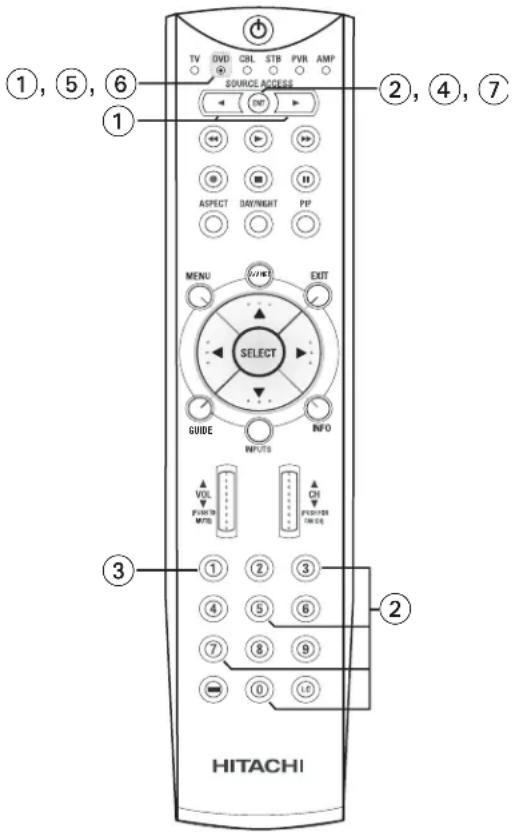
NOTES: 1. This feature is optional.
- Assigned input numbers can be used more than once if applicable.
THE REMOTE CONTROL
| VCR BRAND | CODE |
| ABS | 1972 |
| Admiral | 0048, 0209 |
| Adventura | 0000 |
| Aiko | 0278 |
| Aiwa | 0000, 0037, 0307 |
| Akai | 0041, 0061, 0106 |
| Alienware | 1972 |
| America Action | 0278 |
| American High | 0035 |
| Asha | 0240 |
| Audiovox | 0037, 0278 |
| Beaumark | 0240 |
| Bell & Howell | 0104 |
| Broksonic | 0121, 0184, 0002, 0209, 0479 |
| CCE | 0072, 0278 |
| Calix | 0037 |
| Canon | 0035 |
| Carver | 0081 |
| Cineral | 0278 |
| Citizen | 0278, 0037 |
| Colt | 0072 |
| Craig | 0037, 0072, 0047, 0240, 0271 |
| Curtis Mathes | 0035, 0041, 0060, 0162 |
| CyberPower | 1972 |
| Cybernex | 0240 |
| Daewoo | 0278, 0045, 0561 |
| Dell | 1972 |
| Denon | 0042 |
| Durabrand | 0039, 0038 |
| Dynatech | 0000 |
| Electrohome | 0037 |
| Electrophonic | 0037 |
| Emerex | 0032 |
| Emerson | 0037, 0184, 000, 0121, 0043, 0209, 0002, 0278, 0061, 0208, 0212, 0479, 0561, 1593 |
| Fisher | 0104, 0047, 0066 |
| Fuji | 0033, 0035 |
| Funai | 0000, 1593 |
| GE | 0035, 0060, 0240, 0202, 0761 |
| Garrard | 0000 |
| Gateway | 1972 |
| Go Video | 0432, 0526 |
| GoldStar | 0037, 0038 |
| Gradiente | 0000, 0008 |
| HI-Q | 0047 |
| HP | 1972 |
| Harley Davidson | 0000 |
| Harman/Kardon | 0038, 0081 |
| Harwood | 0072 |
| Headquarter | 0046 |
| Hewlett Packard | 1972 |
| Hitachi | 0000, 0041, 0042, 0105 |
| Howard Computers | 1972 |
| Hughes Network Systems | 0042 |
| iBuy Power | 1972 |
| JVC | 0067, 0041, 0008 |
| Jensen | 0041 |
| KEC | 0037, 0278 |
| KLH | 0072 |
| Kenwood | 0041, 0067, 0038 |
| Kodak | 0035, 0037 |
| LG | 0037 |
| LXI | 0037 |
| Lloyd's | 0000, 0208 |
| Logik | 0072 |
| MEI | 0035 |
| MGA | 0043, 0240, 0061 |
| MGN Technology | 0240 |
| MTC | 0000, 0240 |
| Magnasonic | 0593 |
| Magnavox | 0035, 0081, 0563, 0000, 0039, 0593 |
| Magnin | 0240 |
| Marantz | 0081, 0035 |
| Marta | 0037 |
| Matsushita | 0035, 0162, 1162 |
| Media Center PC | 1972 |
| Memorex | 0035, 0162, 0037, 0048, 0039, 0047, 0240, 0000, 0104, 0209, 0046, 0307, 0479, 1037, 1162, 1262 |
| Microsoft | 1972 |
| Mind | 1972 |
| Minolta | 0042, 0105 |
| Mitsubishi | 0061, 0043, 0067 |
| Motorola | 0035, 0048 |
| Multitech | 0000, 0072 |
| NEC | 0038, 0041, 0067, 0104 |
| Nikko | 0037 |
| Noblex | 0240 |
| Northgate | 1972 |
| Olympus | 0035 |
| Optimus | 0593, 1062, 0162, 0037, 0048, 0104, 0432, 1048, 1162, 1262 |
| Optionica | 0062 |
| Orion | 0184, 0209, 0002, 0479 |
| Panasonic | 0162, 1062, 0035, 0616, 1162, 1262 |
| Penney | 0035, 0037, 0240, 0042, 0038 |
| Pentax | 0042, 0105 |
| Philco | 0035, 0209, 0479, 0561 |
| Philips | 0081, 0035, 0618, 1081, 1181, 0062 |
| Pilot | 0037 |
| Pioneer | 0067 |
| Polk Audio | 0081 |
| Profitronic | 0240 |
| Proscan | 0060, 0202, 0761 |
| Protec | 0072 |
| Pulsar | 0039 |
| Quarter | 0046 |
| Quartz | 0046 |
| Quasar | 0035, 0162, 1162 |
| RCA | 0060, 0240, 0042, 0105, 0106, 0202, 0761, 0880 |
| Radio Shack | 0000, 1037 |
| Radix | 0037 |
| Randex | 0037 |
| Realistic | 0035, 0037, 0048, 0047, 0000, 0104, 0046, 0062, 0066 |
| ReplayTV | 0614, 0616 |
| Runco | 0039 |
| STS | 0042 |
| Samsung | 0045, 0240, 0432 |
| Sanky | 0039, 0048 |
| Sansui | 0000, 0067, 0209, 0041, 0479, 1479, 0271 |
| Sanyo | 0047, 0240, 0104, 0046 |
| Scott | 0184, 0045, 0121, 0043, 0210, 0212 |
| Sears | 0035, 0037, 0047, 0000, 0042, 0104, 1237, 0046, 0066, 0105 |
| Semp | 0045 |
| Sharp | 0048, 0848, 0062 |
| Shintom | 0072 |
| Shogun | 0240 |
| Singer | 0072 |
| Sonic Blue | 0614, 0616 |
| Sony | 0035, 0032, 0000, 0033, 0636, 1032, 1972 |
| Sylvania | 0035, 0081, 0000, 0043, 0593, 1593 |
| Symphonic | 0000, 0593, 1593 |
| Systemax | 1972 |
| TMK | 0240, 0208 |
| Tagar Systems | 1972 |
| Tatung | 0041 |
| Teac | 0000, 0041 |
| Technics | 0035, 0162 |
| Teknika | 0000, 0035, 0037 |
| Thomas | 0000 |
| Tivo | 0618, 0636, 1503 |
| Toshiba | 0045, 0043, 0066, 0210, 0212, 0366, 0845, 1008, 1145, 1503, 1972 |
| Totevision | 0037, 0240 |
| Touch | 1972 |
| Unitech | 0240 |
| Vector | 0045 |
| Vector Research | 0038 |
| Video Concepts | 0045, 0061 |
| Videomagic | 0037 |
| Videosonic | 0240 |
| Viewsonic | 1972 |
| Wards. 0060, 0062, 0035, 0048, 0047,0081, 0240, 0000, 0042, 0072, 0212 | |
| White Westinghouse | 0072, 0209 |
| XR-1000 | 0072, 0000, 0035 |
| Yamaha | 0038 |
| ZT Group | 1972 |
| Zenith | 0039, 0000, 0209, 0033,0479, 1479 |
| DVD BRAND CODE | |
| AMW | 0872 |
| Aiwa | 0641 |
| Allegro | 0869 |
| Apex Digital | 0672, 0717, 0755, 0794,0796, 0797, 1004, 1020,1056, 1061, 1100, 1915, 1937 |
| Audiovox | 0790, 1072 |
| Axion | 1072 |
| Blaupunkt | 0717 |
| Blue Parade | 0571 |
| Brooksonic | 0695 |
| CAVS | 1057 |
| CineVision | 0876, 0869 |
| Classic | 1917 |
| Coby | 1086 |
| Curtis Mathes | 1087 |
| CyberHome | 0816, 1023, 1024 |
| DVD2000 | 0521 |
| Daewoo | 0784, 0705,0833, 0869, 1918 |
| Denon | 0490, 0634 |
| Dual | 1068, 1085 |
| Emerson | 0591, 0675 |
| Enterprise | 0591 |
| Fisher | 0670 |
| Funai | 0675 |
| GE | 0522, 0717, 0815 |
| GPX | 0699, 0769 |
| Gateway | 1073 |
| Go Video | 0744, 0715, 0783,0833, 0869, 1075 |
| Gradiente | 0651 |
| Greenhill | 0717 |
| Grundig | 0705 |
| Harman/Kardon | 0702 |
| Hitachi | 0573, 0664, 0695 |
| Hiteker | 0672 |
| IRT | 0783 |
| Initial | 0717 |
| Integra | 0627 |
| Hiteker | 0672 |
| JBL | 0702 |
| JVC | 0623, 0558, 0867, 1901 |
| KLH | 0717, 0790, 1020 |
| Kawasaki | 0790 |
| Kenwood | 0490, 0534 |
| Koss | 0651 |
| Lasonic | 0798 |
| Lite-On | 1058 |
| Magnavox | 0503, 0675, 1914, 1976 |
| Marantz | 0539 |
| Memorex | 0695 |
| Microsoft | 0522 |
| Mintek | 0717, 0839 |
| Mitsubishi | 0521, 1521 |
| Nesa | 0717 |
| Norcent | 1003, 0872 |
| Onkyo | 0627, 0503 |
| Oritron | 0651 |
| Panasonic | 0490 |
| Philco | 0790 |
| Philips | 0503, 0539, 0646, 0854 |
| Pioneer | 0525, 0571, 1902 |
| Polaroid | 1061, 1086 |
| Polk Audio | 0539 |
| Proscan | 0522 |
| Qwestar | 0651 |
| RCA | 0522, 0571, 0717, 0790, 0822, 1974 |
| Recco | 0698 |
| Rio | 0869 |
| Rotel | 0623 |
| Rowa | 0823 |
| Sampo. | 0698, 0752 |
| Samsung | 0490, 0573, 0820, 0744, 1075 |
| Sansui | 0695 |
| Sanyo | 0670, 0695, 0873 |
| Semp | 0503 |
| Sharp | 0630, 0752 |
| Shinsonic | 0533, 0839 |
| Sonic Blue | 0869 |
| Sony | 0533 |
| Sylvania | 0675 |
| Symphonic | 0675 |
| TYT | 0705 |
| Teac | 0790 |
| Technics | 0490 |
| Theta Digital | 0571 |
| Tivo | 1996 |
| Toshiba | 0503, 0695, 1045, 1988, 1996, 2006 |
| Tredex | 0799, 0803 |
| US Logic | 0839 |
| Urban Concepts | 0503 |
| Venturer | 0790 |
| XBox | 0522 |
| Yamaha | 0490, 0545, 0539 |
| Zenith | 0591, 0503, 0869 |
| CABLE BRAND | CODE |
| ABC . 0003, 0008, 0011, 0013, 0014, . . . . . . . . . . . . . . . . . . . . . . . . . . . . . . . . . . . . . . . . . . . . . . . . . . . . . . . . . . . . . . . . . . . . . . . . . . . . . . . . . . . . . . . . . . . . . . . . . . . . | 0017 |
| Allegro . . . . . . . . . . . . . . . . . . . . . . . . . . . . . . . . . . . . . . . . . . . . . . . . . . . . . . . . . . . . . . . . . . . . . . . . . . . . . . . . . . . . . . . . . . . . . . . . . . . .. . . . . . . . . . . . . . . . . . . . . . . . . . . . . . . . . . . . . . . . . . . . . . . . . . . . . . . . . . . . . . . . . . . . . . . . . . . . . . . . . . . . . . . . . . . . . . . . . . . . | |
| Americast . . . . . . . . . . . . . . . . . . . . . . . . . . . . . . . . . . . . . . . . . . . . . . . . . . . . . . . . . . . . . . . . . . . . . . . . . . . . . . . . . . . . . . . . . . . . . . . . . . . | |
| Antronix . . . . . . . . . . . . . . . . . . . . . . . . . . . . . . . . . . . . . . . . . . . . . . . . . . . . . . . . . . . . . . . . . . . . . . . . . . . . . . . . . . . . . . . . . . . . . . . . . . . : | |
| Archer . . . . . . . . . . . . . . . . . . . . . . . . . . . . . . . . . . . . . . . . . . . . . . . . . . . . . . . . . . . . . . . . . . . . . . . . . . . . . . . . . . . . . . . . . . . . . . . . . . . 022 | 0797 |
| Bell & Howel. . . . . . . . . . . . . . . . . . . . . . . . . . . . . . . . . . . . . . . . . . . . . . . . . . . . . . . . . . . . . . . . . . . . . . . . . . . . . . . . . . . . . . . . . . . . . . . . . . . .0014 | |
| Bell South . . . . . . . . . . . . . . . . . . . . . . . . . . . . . . . . . . . . . . . . . . . . . . Cabletenna. . . . . . . . . . . . . . . . . . . . . . . . . . Cableview. . . . . . . . . . . . . . . . . . . . . . . Century. . . . . . . . . . . . . . . . . . . . . . . . . . Citizen. . . . . . . . . . . . . . . . . . . 0153, 0315 | |
| ClearMax. . . . . . . . . . . . . . . . . Clearmaster. . . . . . . . . . . . . . . Colour Voice. 0025, 0031 Comtronics.0040 Contec.0019 Coolmax.0883 Digi.0637 Director.0476 Dumont.0637 Emerson.0797 Everquest.0015, 0040 Focus.0400 Garrard.0153 Gemini.0015, 0797 General Instrument.0003, 0011, 0476, 0276, 0810 GoldStar.0040, 0144 Goodmind.0797 Hamlin.0009, 0020, 0034, 0273 Hitachi.0011 Jasco.0015, 0153, 0315 Jerrold.0003, 0011, 0012, 0014, 0015, 0024, 0276, 0476, 0810 Memorex.0000 Motorola.0276, 0476, 0810, 1106, 1254, 1376 Movie Time.0063 Multivision.0012 | |
NSC....0063
Novaplex 0618
Oak 0019
Optimus 0021
Pace 0237, 1877
Panasonic 0000, 0021, 0107
Panther 0637
Paragon. 0000
Philips 0305, 0317
Pioneer.....0023, 0025, 0031, 0153,
0144, 0533, 0877, 1877
Popular Mechanics ..... 0400
Pulsar 0000
Quasar 0000
RCA....0021
RadioShack. . . 0015, 0315, 0797, 0883
Recoton 0400
Regal....0020, 0273, 0279
Rembrandt....0011
Runco 0000
SL Marx 0040
Samsung 0040, 0144
Scientific Atlanta. 0877, 0008,
0017, 0477, 1877
Signal 0015.0040
Signature 0011
Sony 1006
Sprucer 0021
Starcom. 0003, 0015
Stargate....0015, 0040, 0797
Starquest 0015
Supercable 0276
Supermax 0883
TFC 0310
TV86 0063
Tandy. 0258
TeleCaption 0221
Teleview. 0040
Timeless 0040
Tocom 0012, 0013
Torx 0003
Toshiba 0000
Tristar 0883
Tusa. 0015
Unika 0022, 0153
Universal ..... 0022, 0153, 0191
V2 0883
ViewMaster 0883
Viewstar. 0063, 0258
Vision. 0883
Vortex View 0883
Zenith ..... 0000, 0054, 0525, 0899
Zentek 0400
SATELLITE BRAND (Set-Top-Box) .. CODE
| AlphaStar | 0772 |
| Amway | 0043, 0075 |
| Astro Industries | 0095 |
| BSR | 0095 |
| Cable Innovations | 0554 |
| Capetronic | 0095 |
| Century | 0856 |
| Channel Master | 0018, 0212 |
| Chapparral | 0053, 0209, 0216 |
| Conifer | 0004 |
| Crossdigital | 1109 |
| Curtis Mathes | 061 |
| DX Antenna | 0041 |
| DirecTV 0392, 0566, 0639, 1639, 1142,0247, 0749, 1749, 0724, 0819,1856, 1076, 1109, 0099, 1052,1053, 1054, 1442, 1443, 1444 | |
| Dish Network System | 1005, 0775, 1170 |
| DishPro | 1005, 0775 |
| Drake | 0018, 0064, 0245 |
| Echostar | 1005, 0775, 0148,0269, 0280, 1170 |
| Expressvu | 0775 |
| GE | 0566 |
GOI 0775
General Instrument . . 0869, 0547, 0554
Gradiente....0856
HTS 0775
Hitachi 0819
homecable....0238
Hughes Network Systems ..... 1142,
0749, 1749, 1442, 1443, 1444
Hytek 0095
IQ....0210
IQ Prism 0210
Innova 0099
Intersat 0043
JVC 0775, 1170
Janeil 0152
Legend 0269
Macom....0018, 0061
Magnavox 0724, 0722
Memorex 0724, 0269
Mitsubishi 0749
Motorola 0869
Netsat 0099
Next Level 0869
Norsat 0004
Pace 0455
Panasonic ..... 0247, 0701, 0152
Paysat 0724
Philips.....1142, 0749, 0724, 1076,
.....0722, 1749, 0856, 0099
Pico 0075
Proscan 0392, 0566
RCA. . . . . . . 0392, 0566, 0855, 0143
Radioshack 0869, 0554
Ramsey 0075
Realistic.....0052
SKY 0856, 1856, 0099
STS 0041, 0210
Samsung 1276, 1109
Sony 0639, 1639
Star Choice 0869
Star Trak ..... 0180, 0421, 0547
Strong 0421
Tivo ..... 1142, 1442, 1443, 1444
Toshiba....0749, 1749, 0790,
.....0061, 0082, 1052, 1053.
1054, 1285, 1286, 1287, 1289
Town & Country. 0547
Uniden ..... 0724, 0722, 0052, 0074,
.....0076, 0238, 0370, 0554
Zenith ..... 0856, 1856, 0061, 0064
AMPLIFIER BRAND.....CODE
| Aiwa | .0406 |
| Bose | .0674 |
| Carver | .0269 |
| Curtis Mathes | .0300 |
| Denon | .0160 |
| Durabrand | .1561 |
| GE | .0078 |
| Harman/Kardon | .0892 |
| JVC | .0331 |
| Left Coast | .0892 |
| Lenoxx | .1561 |
| Linn | .0269 |
| Luxman | .0165 |
| Magnavox | .0269 |
| Marantz | .0269, 0321, 0892 |
| NEC | .0264 |
| Nakamichi | .0321 |
| Optimus | .0395, 0300 |
| Panasonic | .0308, 0521 |
| Parasound | .0246 |
| Philips | .0269, 0892 |
| Pioneer | .0013, 0300 |
| Polk Audio | .0269, 0892 |
| RCA | .0300 |
| Realistic | .0395 |
| Sansui | .0321 |
| Shure | .0264 |
| Sony | .0815, 0689, 0220 |
Soundesign 0078, 0211
Technics 0308, 0521
Toshiba 0353
Victor 0331
Wards 0013, 0078, 0211
Yamaha 0354, 0133
RECEIVER BRAND (Amplifier) CODE
| ADC. | 0531 |
| Aiwa . 1405, 0121, 0158, 0189, 0405 | |
| Anam. | 1074, 1609 |
| Arcam | 1120 |
| Audiotronic | 1189 |
| Bose | 0639, 1229, 1253 |
| Capetronic | 0531 |
| Carver | 1189, 0042, 0189 |
| Casio | 0195 |
| Clarinette | 0195 |
| Coby | 1263 |
| Compaq | 1136 |
| Curtis Mathes | 0080 |
| Dell | 1383 |
| Denon | .0004, 1360 |
| Fisher | 0042 |
| Garrard | 0463 |
| Glory Horse | 1263 |
| Harman/Kardon | 0891, 0110, 0189 |
Hewlett Packard 1181
Hitachi 0228
Integra 0135
JBL. 0110
JVC 0074, 1263
KLH 1428
Kenwood ..... 1313, 1570, 1569,
0027, 0042, 0186, 0239
LXI 0181
Linn.0189
Lloyd's 0195
MCS 0039
Magnavox....1189, 1269, 0189, 0195,
0391, 0531
Marantz ..... 1189, 0039, 0189, 1269
Mitsubishi 1393
Modulaire....0195
Musicmagic 1089
Nakamichi 0097
Onkyo 0135, 0842
Optimus ..... 1023, 0042, 0080, 0177,
0181, 0186, 0219, 0531,
.0670.0738.0801.1074
Panasonic . . . 1518, 0039, 0309, 0367
Penney 0195
Philips .. 1189, 1269, 0189, 0391, 1120
Pioneer....1023, 0014, 0080,
0150, 0244, 0531, 0630
Polk Audio 0189
Proscan 1254
Quasar....0039
RCA 1023.1254.0080.
-
- 1609
Radio Shack 1263
Realistic. 0181, 0195
Rio 1383
Sansui 0189
Sanyo 0801 1251
Scott 0163.0322
Sharp. 0186
Sharper Image 1263
Sherwood 0491, 0502
Sonic Blue 1383
Sony.....1058, 1441, 1759, 0158,
0474, 1349, 1406, 1442
Soundesign 0670
Stereophonics 1023
Sunfire 1313
Teac. 0463, 1074
Technics ..... 1308, 1518, 0039, 0309
Thorens 1189
Toshiba 1572
Victor 0074
Wards.....0014, 0080, 0158, 0189
Yamaha 0176, 0186, 1176
Yorx. 0195
Zenith 0857
AUDIO BRAND .... CODE
| Aiwa. | 0010, 0159 |
| AudioSource | 0351 |
| Cambridge Soundworks | 0351 |
| Carver | 0351 |
| Fisher | 0052 |
| Fosgate | 0259 |
| Harmon/Kardon | 0477 |
| JBL | 0477 |
| JVC | 0073 |
| KLH | 0351 |
| Magnavox | 0325 |
| Nikko | 0376 |
| Paramount Pictures | 0317, 0351 |
| RCA | 0056 |
| SSI | 0317 |
| Sansui | 0325 |
| Schneider | 0376 |
| Sony | 0010, 0576 |
| Soundesign | 0376 |
| Yorx | 0376 |
SET TOP BOX BRAND ..... CODE
| Panasonic | 1120 |
| Pioneer | 1010 |
| Princeton | 0113, 0295 |
| Samsung | 1190 |
| Sensory Science | 1126 |
| Sharp | 1010 |
| Sony | 0639 |
| PERSONAL VIDEO RECORDER | |
| BRAND | CODE |
| Panasonic | 0616 |
| Philips | 0618 |
| ReplayTV | 0614, 0616 |
| SonicBlue | 0614, 0616 |
| Sony | 0636 |
| Tivo | 0618, 0636 |
- Press MENU on the remote control to display the different features on your HITACHI LCD TV.
- Use the CURSOR PAD to navigate to a different menu item.
- Press EXIT on the remote control to quickly exit from a menu.
- Press the A/V NET button on the remote control to access the AV Network menu to control external components.
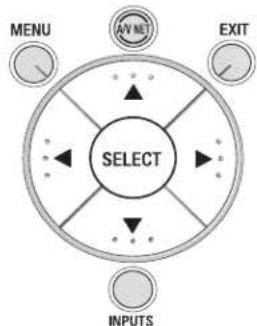
flowchart
graph TD
    A["SELECT"] --> B["AV ME"]
    A --> C["EXIT"]
    A --> D["INPUTS"]
    style A fill:#f9f,stroke:#333
    style B fill:#ccf,stroke:#333
    style C fill:#ccf,stroke:#333
    style D fill:#cfc,stroke:#333
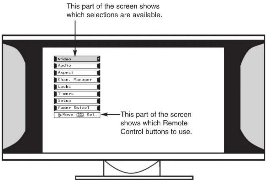
OSD (On-Screen Display)
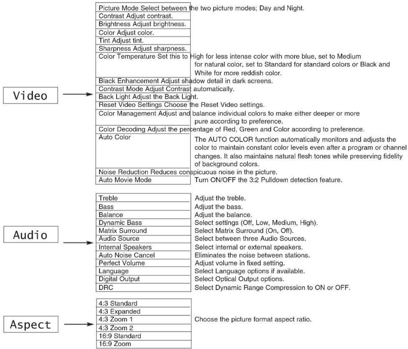
NOTE: The Language, Digital Output, and the Dynamic Range Compression feature of the Audio OSD are only available for Digital channels.
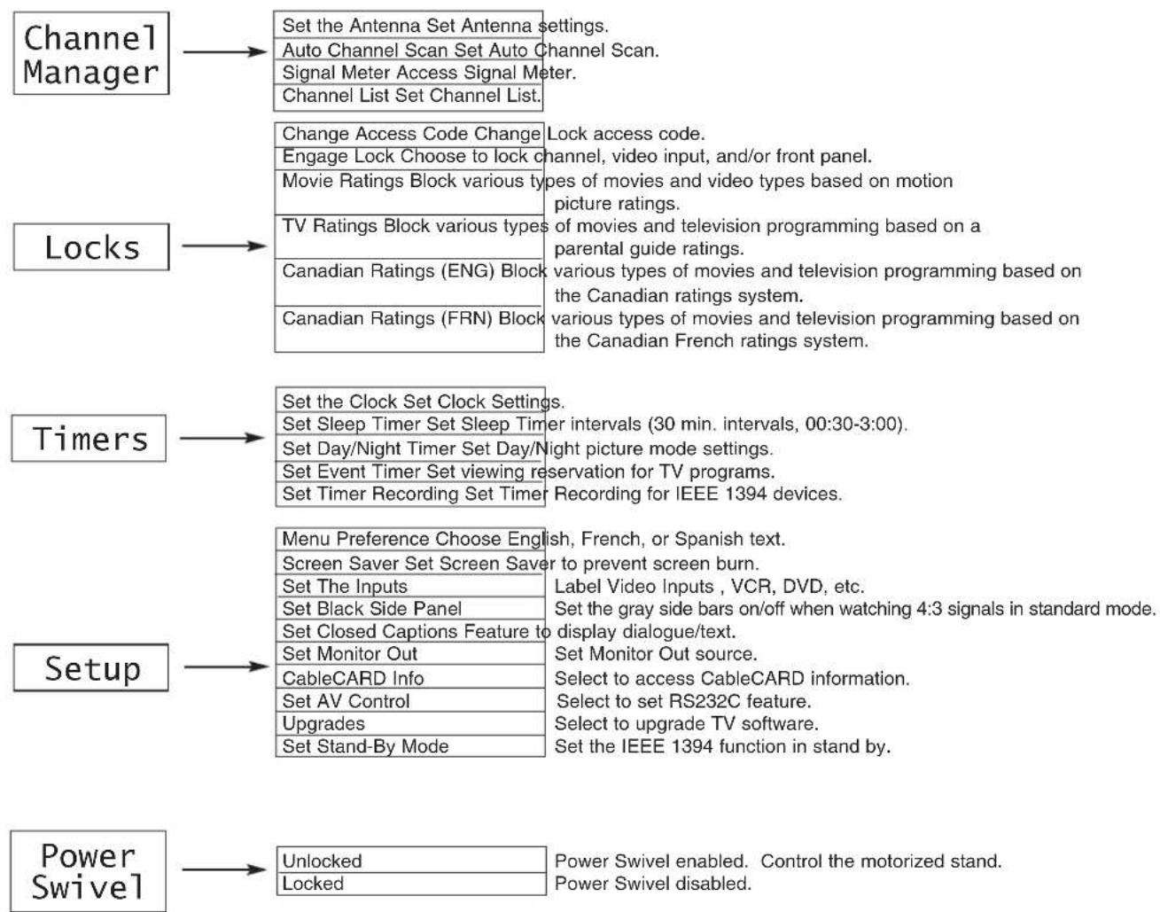
flowchart
graph TD
    A["Channel Manager"] --> B["Set the Antenna Set Antenna settings."]
    A --> C["Auto Channel Scan Set Auto Channel Scan."]
    A --> D["Signal Meter Access Signal Meter."]
    A --> E["Channel List Set Channel List."]

    F["Locks"] --> G["Change Access Code Change Lock access code."]
    F --> H["Engage Lock Choose to lock types of movies and video types based on motion picture ratings."]
    F --> I["Movie Ratings Block various types of movies and television programming based on a parental guide ratings."]
    F --> J["TV Ratings Block various types of movies and television programming based on the Canadian ratings system."]
    F --> K["Canadian Ratings (ENG) Block various types of movies and television programming based on the Canadian French ratings system."]
    F --> L["Canadian Ratings (FRN) Block various types of movies and television programming based on the Canadian French ratings system."]

    M["Timers"] --> N["Set the Clock Set Clock Settings."]
    M --> O["Set Sleep Timer Set Sleep Timer intervals (30 min. intervals, 00:30-3:00)."]
    M --> P["Set Day/Night Timer Set Day/Night picture mode settings."]
    M --> Q["Set Event Timer Set viewing reservation for TV programs."]
    M --> R["Set Timer Recording Set Timer Recording for IEEE 1394 devices."]

    S["Setup"] --> T["Menu Preference Choose English, French, or Spanish text."]
    S --> U["Screen Saver Set Screen Saver to prevent screen burn."]
    S --> V["Set The Inputs Label Video Inputs, VCR, DVD, etc."]
    S --> W["Set Black Side Panel Set the gray side bars on/off when watching 4:3 signals in standard mode."]
    S --> X["Set Closed Captions Feature to display dialogue/text."]
    S --> Y["Set Monitor Out Set Monitor Out source."]
    S --> Z["CableCARD Info Select to access CableCARD information."]
    S --> AA["Set AV Control Select to set RS232C feature."]
    S --> AB["Upgrades Select to upgrade TV software."]
    S --> AC["Set Stand-By Mode Set the IEEE 1394 function in stand by."]

    AD["Power Swivel"] --> AE["Unlocked Power Swivel enabled. Control the motorized stand."]
    AD --> AF["Locked Power Swivel disabled."]
NOTES: 1. The Signal Meter feature of the Channel Manager OSD is only available for Digital signals.
- The CableCARD information feature of the Setup OSD is only available when a CableCARD from your cable operator is installed in the rear panel of the Audio Video Control Center (AVC).
Video
Select VIDEO to adjust picture settings and improve picture quality. You can independently customize each of the Video Inputs to your preference to increase viewing performance and pleasure depending upon the video program being viewed. If RESET is selected, only the selected input will reset to initial conditions.
Picture Mode
Use this function to choose from automatic picture settings to optimize your TV's performance.
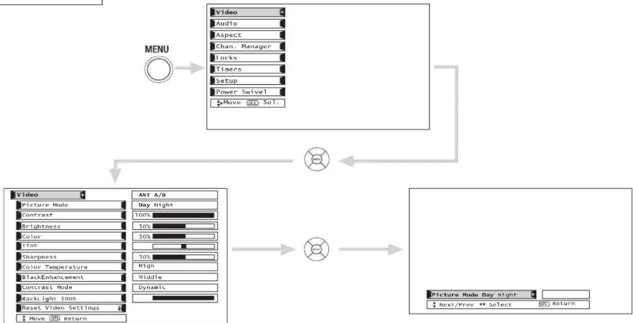
flowchart
graph TD
    A["MENU"] --> B["Video"]
    B --> C["Audio"]
    B --> D["Aspect"]
    B --> E["Chan. Manager"]
    B --> F["Locks"]
    B --> G["Timers"]
    B --> H["Setup"]
    B --> I["Power Swivel"]
    B --> J["Move SEL Sel."]
    C --> K["ANT A/B"]
    D --> L["Day Night"]
    E --> M["Brightness"]
    F --> N["Color"]
    G --> O["Tint"]
    H --> P["Sharpness"]
    I --> Q["Color Temperature"]
    J --> R["BlackEnhancement"]
    K --> S["Dynamic"]
    L --> T["High"]
    M --> U["Middle"]
    N --> V["Backlight 100%"]
    O --> W["Reset Video Settings"]
    P --> X["Move SEL Return"]
    Q --> Y["Picture Mode Day Night"]
    R --> Z["Next/Prev Select SEL Return"]
Use CURSOR PAD ◀ or ▶ to highlight and select Picture Mode settings.
| Function | Day | Night | Reset |
| Contrast 100% 91% | Reset the video menu settings on current input to the Day or Night conditions depending on the selected VIDEO mode. | ||
| Brightness 50% 53% | |||
| Color 50% 25% | |||
| Tint 50% 50% | |||
| Sharpness 50% 40% | |||
| Color Temperature | High | Standard | |
| Black Enhancement | Low | Off | |
| Contrast Mode | Dynamic | Normal | |
| Back Light 100% 50% | |||
| Auto Color | Off | Off | |
| Noise Reduction | Low | Off | |
| Color Management (Set User Colors) | Off | Off | |
| Auto Movie Mode (TV/Cinema Detection) | Off | On |
Press EXIT to quit menu or select PICTURE MODE to return to previous menu.
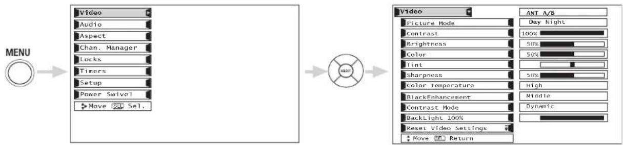
flowchart
graph LR
    A["MENU"] --> B["Video"]
    B --> C["Audio"]
    C --> D["Aspect"]
    D --> E["Chan. Manager"]
    E --> F["Locks"]
    F --> G["Timers"]
    G --> H["Setup"]
    H --> I["Power Swivel"]
    I --> J["Move Sel."]

    K["Video"] --> L["Picture Mode"]
    L --> M["Contrast"]
    M --> N["Brightness"]
    N --> O["Color"]
    O --> P["Tint"]
    P --> Q["Sharpness"]
    Q --> R["Color Temperature"]
    R --> S["BlackEnhancement"]
    S --> T["Contrast Mode"]
    T --> U["BackLight 100%"]
    U --> V["Reset Video Settings"]
    V --> W["Move Return"]

    X["ANT A/B"] --> Y["Day Night"]
    Y --> Z["100%"]
    Z --> AA["50%"]
    AA --> AB["50%"]
    AB --> AC["50%"]
    AC --> AD["High"]
    AD --> AE["Middle"]
    AE --> AF["Dynamic"]
Use the CURSOR PAD ▲ or ▼ to highlight the function to be adjusted.
Press down on CURSOR PAD to select the function settings.
Press the CURSOR PAD ◀ or ▶ to adjust the function.
Press MENU to return to main menu.
Press EXIT to quit menu.
Contrast
Use this function to change the contrast between black and white levels in the picture.
Brightness
Use this function to adjust overall picture brightness.
Color
Use this function to adjust the level of color in the picture.
Tint
Use this function to adjust flesh tones so they appear natural.
Sharpness
Use this function to adjust the amount of fine detail in the picture.
Color Temperature
Set this to High for cooler color with more blue, set to Medium for more natural color, set to Standard for accurate color or set to Black/White for more reddish color.
Black Enhancement
Use this function to enhance the shadow detail in dark scenes using the settings off, low, middle and high.
NOTES: 1. If CONTRAST is selected, you are adjusting CONTRAST. The additional menu items BRIGHTNESS, COLOR, TINT, and SHARPNESS can be selected and adjusted in the same manner.
- It may be necessary to adjust TINT to obtain optimum picture quality when using the COMPONENT VIDEO Y-P B P R input jacks.
Contrast Mode
Use this function to choose between 3 Contrast Mode settings. Set to Dynamic for darker images more in the level of Black, set to Normal for a balanced White to Black level, and set to Auto for automatic Contrast selection.
Back Light
Use this function to adjust the amount of Back Light.
Reset Video Settings
This function allows you to Reset the Video Menu Settings of the present input and return it to the Day VIDEO mode.
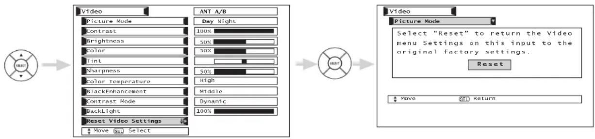
flowchart
graph LR
    A["Original Mode"] --> B["Video"]
    B --> C["Picture Mode"]
    C --> D["Contrast"]
    D --> E["Brightness"]
    E --> F["Color"]
    F --> G["Tint"]
    G --> H["Sharpness"]
    H --> I["Color Temperature"]
    I --> J["BlackEnhancement"]
    J --> K["Contrast Mode"]
    K --> L["BackLight"]
    L --> M["Reset Video Settings"]
    M --> N["Move Select"]
    B --> O["ANT A/B"]
    O --> P["Day Night"]
    P --> Q["100%"]
    Q --> R["50%"]
    R --> S["50%"]
    S --> T["50%"]
    T --> U["High"]
    U --> V["Middle"]
    V --> W["Dynamic"]
    W --> X["100%"]
Use CURSOR PAD to highlight functions.
Press the SELECT button to select Reset Video Settings.
Use the CURSOR PAD ▼ to access other video settings.
You can customize each of the Video Inputs to your preference to increase viewing performance and pleasure, depending upon the video program being viewed. If RESET is selected, only the selected Input will reset to the initial conditions as explained above.
If RESET is selected in Video:1 Input, only Video:1 Input will return to factory conditions.
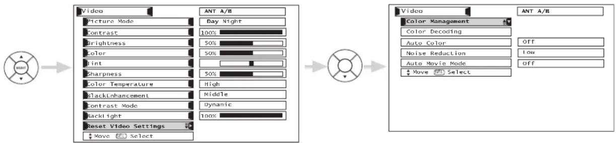
Color Management
Use this function to adjust and balance the listed individual colors to make them either deeper or more pure depending on the user's preference. Adjust the GAIN settings to make the color brighter (+) or darker (-). Adjust the PHASE settings to make the colors deeper (+) or normal (-) to match real life colors.
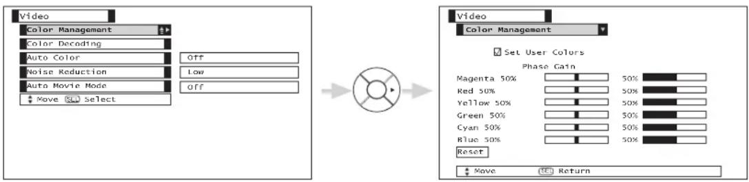
Use the CURSOR PAD to highlight function.
Press the SELECT button to select User Colors setting. When the function has a “√” in the box, it is ON.
Press the CURSOR PAD ◀, ▶, ▼, ▲, to highlight and adjust individual colors.
Use the CURSOR PAD to highlight and select "Reset" to return all colors to default settings.
NOTE: When the Set User Colors box is not checked, the listed colors will be grayed out.
Color Decoding
Use this function to adjust and balance the percentage of Red, Green and Blue according to the user's preference in each of the four color temperature settings. Use TINT to adjust flesh tones so they appear natural.
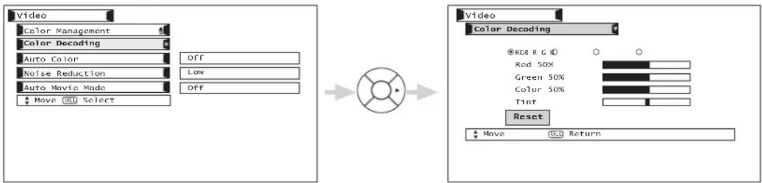
Use CURSOR PAD to highlight function.
Press down to select from 4 menu items.
Press CURSOR PAD ◀, ▶, ▼, ▲, to highlight and adjust Red, Green, Color and Tint.
Use CURSOR PAD to highlight and select "Reset" to return all settings to default.
NOTE: Color Decoding settings are independently stored in each of the 4 Color Temperature settings.
Auto Color
The AUTO COLOR function automatically monitors and adjusts the color to maintain constant color levels even after a program or channel changes. It also maintains natural flesh tones while preserving fidelity of background colors.
NOTE: When using Component or DVI-HDTV input, Auto Color will not be available (grayed out).
Noise Reduction
The NOISE REDUCTION function automatically reduces conspicuous noise in the picture without degrading picture quality. Set NOISE REDUCTION to OFF if the TV experiences picture blocking.
Auto Movie Mode
The Auto Movie Mode function turns ON or OFF the 3:2 PULLDOWN DETECTION SPECIAL FEATURE. Theatrical movies are shot on film at 24 frames or still pictures per second, instead of 30 frames or 60 fields like video. When film is transferred to video for television viewing, the disparity between the two frame rates must be reconciled. This involves a process known as 3:2 pulldown.
When Auto Movie Mode is turned ON from the VIDEO menu, your Hitachi LCD Television will activate the circuitry for this special feature to improve video performance when watching film based sources.
NOTES: 1. When using Progressive Scan Component or HDMI OR DVI input (Ex. 480p, 720p), Auto Movie Mode will not be available (grayed out). Please see table below for additional information.
| ANT A/B, VIDEO, 480i 480p/720p/1080i | ||
| 32” AVAILABLE GRAYED OUT | ||
- All Video settings are independent of each other based on it's input (ANT A/B, Input 1\~5, Photo Input).
AUDIO
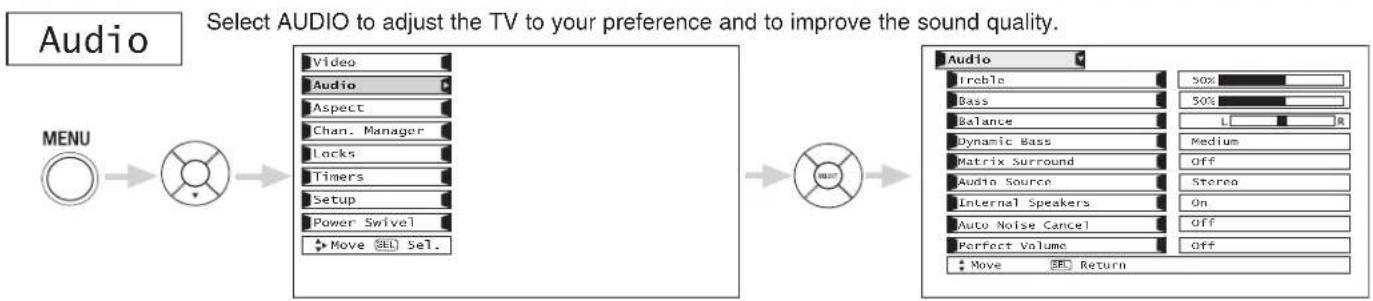
flowchart
graph LR
    A["MENU"] --> B["Select Audio to adjust the TV to your preference and to improve the sound quality."]
    B --> C["Audio Level: Treeble 50%, Bass 50%, Balance L R"]
    C --> D["Audio Source: Internal Speakers On, Auto Noise Cancel Off, Perfect Volume Off"]
    D --> E["Audio Return: Move SEL Sel."]
Press CURSOR PAD ▲, ▼, to select menu item.
Press CURSOR PAD ◀ or ▶ to adjust the function.
Press EXIT to quit the MENU, or select Audio to return to the main menu.
NOTE: If TREBLE is selected you are adjusting treble. The additional menu items Bass and Balance can be selected and adjusted in the same manner.
Treble
This function controls the high frequency audio to all speakers.
Bass
This function controls the low frequency audio to all speakers.
Balance
This function will control the left to right balance of the LCD TV internal speakers.
Dynamic Bass
This function complements and enhances bass performance.
Matrix Surround
The Matrix Surround features the spacious sound effects of a stadium that can be turned ON or OFF.
Audio Source
Multi-Channel Television Sound will allow you to select STEREO (a stereo broadcast), MONO (monaural sound) used when receiving a weak stereo broadcast or 2nd Audio Prog (SAP) which may be a secondary language, weather report, etc. The sources received will be displayed at the top right edge of the TV. The source you select will be displayed above the sources received. See example below for each selection when both stereo and second audio are received (monaural is always received).
STEREO SELECTED
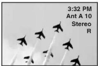
SAP SELECTED
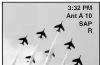
MONO SELECTED
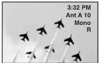
Internal Speakers
This function is useful when setting up the external speakers. If you prefer to use only speakers from a separate stereo system, turn this feature OFF. When set to OFF, the LCD TV speakers and the sub-woofer output are OFF. Also, set to OFF, if you prefer to use only your head-phones.
Auto Noise Cancel
This function eliminates the noise between stations. If a channel is tuned and is noisy, this function will automatically eliminate the audio for that channel.
Perfect Volume
This function will automatically adjust volume so each channel and input has the same average volume level.
Use the functions below if your TV is connected to an amplifier/receiver with optical digital input with Dolby Digital or PCM decoder capabilities.
![Audio Treble 50% Bass 65% Balance R DynamicBass Medium Matrix Surround Off Audio Source Stereo Internal Speakers On Auto Noise Cancel Off Perfect Volume Off Audio Language 1[English] Digital Output Dulby Digital DRC Off Move Select Return Move Move Return](/content/2026/06/1147412/images/910271c8883412655c5f8872a9ce9f8efaf112f91a75aef5b490848d3b58f068.jpg)
Language
Some programs transmit more than one DTV language option. Most will have English as a default language. The language function will allow you to select up to 4 language options (if available).
Digital Output
This function allows you to select between Dolby® Digital and PCM.
Dolby® Digital - Select this feature if the TV is connected to an amplifier/receiver with a Dolby® Digital only decoder; it will provide six independent soundtrack channels through the optical output jack (Digital Audio).
PCM - Select this feature if the TV is connected to an amplifier/receiver with a PCM only decoder; it will provide two independent soundtrack channels through the optical output jack (Digital Audio).
*Manufactured under license from Dolby Laboratories. "Dolby" and the double-D symbol are trademarks of Dolby Laboratories.
DRC
Dynamic Range Compression - Use this function to compress the range of sound volume. By compressing the range of sound volume, it is possible not only to suppress the output of loud sound at night but also to raise the volume of low sound. This is only effective when the TV is connected via the optical out (digital audio) to an amplifier/receiver with a Dolby® Digital decoder. The default setting is ON.
Use the CURSOR PAD ◀, ▶ to select the chosen options.
NOTE: These functions are only available when viewing digital programs.
Aspect
Use this function to select the Picture Format Aspect Ratio.
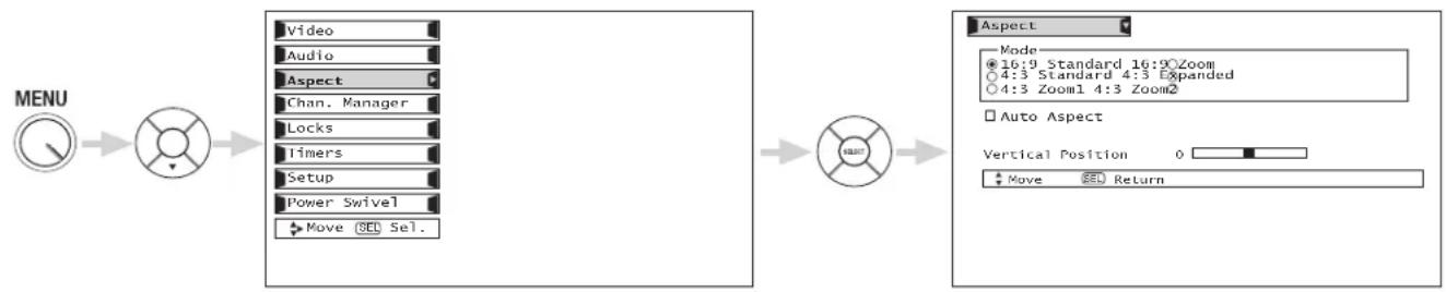
flowchart
graph LR
    A["MENU"] --> B["Switch"]
    B --> C["Video"]
    B --> D["Audio"]
    B --> E["Aspect"]
    B --> F["Chan. Manager"]
    B --> G["Locks"]
    B --> H["Timers"]
    B --> I["Setup"]
    B --> J["Power Swivel"]
    B --> K["Move SEL Sel."]
    L["Aspect"] --> M["Mode"]
    M --> N["16:9 Standard 16:9 Zoom"]
    M --> O["4:3 Standard 4:3 Expanded"]
    M --> P["4:3 Zoom1 4:3 Zoom2"]
    M --> Q["Auto Aspect"]
    Q --> R["Vertical Position 0"]
    Q --> S["Move SEL Return"]
Auto Aspect
Automatically adjust the Aspect Ratio depending on the input signal to fill the screen.
Press CURSOR PAD ▲, ▼, to select menu item.
Press the Select button to select. A "√" in the box indicates that the feature is ON.
NOTES: 1. The Auto Aspect function is recommended on an input signal with VIDEO ID.
2. The Auto Aspect function is best used on composite video, S-Video, and 480i component signals.
3. See page 29 for Aspect Mode availability.
Vertical Position
This function allows you to select when aspect style is either 4:3 EXPANDED/ZOOM1/ZOOM2 or 16:9 ZOOM. Vertical position can be changed with these modes. For example, it will be useful for centering the picture area at both the top and bottom of the picture with 480i/480P signal. Adjustable range is -10 (video center is toward bottom of screen) to +10 (video center is toward top of screen).
Press CURSOR PAD ▲, ▼, to select menu item.
Press CURSOR PAD ◀ or ▶ to adjust the function.
Press EXIT to quit the MENU, or select Aspect to return to the main menu.
NOTE: Vertical Position will not be available in 4:3 Standard and 16:9 Standard modes.
Chan. Manager
Select Channel Manager to set your Antenna options, run Auto Channel Scan, Check Signal Meter and Set Channel List.
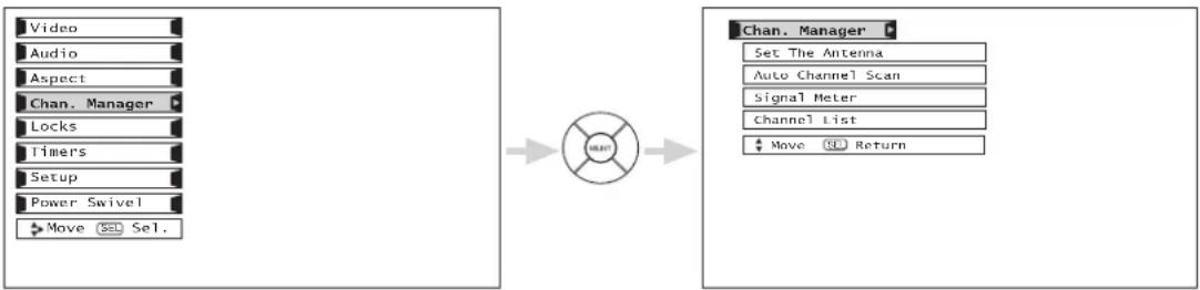
flowchart
graph LR
    A["Video"] --> C((Split))
    B["Audio"] --> C
    D["Aspect"] --> C
    E["Chan. Manager"] --> C
    F["Locks"] --> C
    G["Timers"] --> C
    H["Setup"] --> C
    I["Power Swivel"] --> C
    J["Move Sel."] --> C
    C --> K["Chan. Manager"]
    K --> L["Set The Antenna"]
    K --> M["Auto Channel Scan"]
    K --> N["Signal Meter"]
    K --> O["Channel List"]
    K --> P["Move Sel Return"]
Press CURSOR PAD ▲, ▼ to highlight function, the press the SELECT button to select.
Set The Antenna
This feature will select Antenna options.
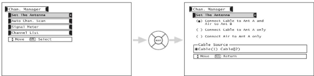
Press CURSOR PAD ▲, ▼ to highlight function, the press the SELECT button to select.
NOTE: When a CableCARD is installed, antenna settings will be set automatically to "Connect Cable to Ant A only".
Auto Channel Scan
This feature will automatically store active Analog and Digital channels in Auto Channel Scan memory.
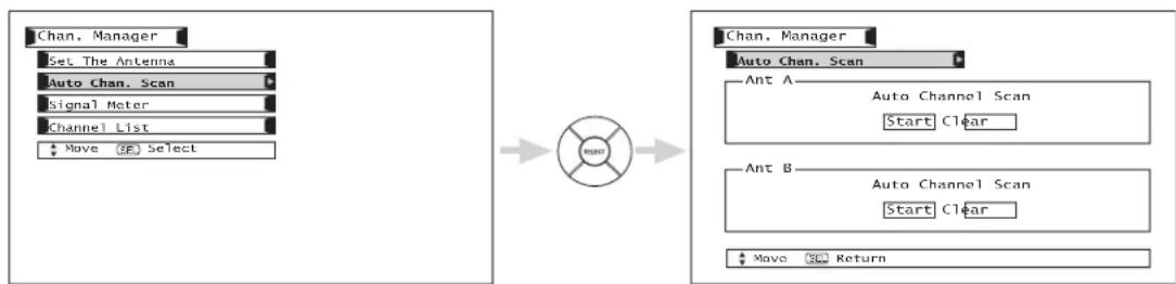
flowchart
graph LR
    A["Chan. Manager"] --> B["Set The Antenna"]
    B --> C["Auto Chan. Scan"]
    C --> D["Signal Meter"]
    D --> E["Channel List"]
    E --> F["Move (SP) Select"]
    G["Chan. Manager"] --> H["Auto Chan. Scan"]
    H --> I["Ant A: Auto Channel Scan Start Clear"]
    J["Chan. Manager"] --> K["Auto Channel Scan Start Clear"]
    L["Chan. Manager"] --> M["Move (SP) Return"]
Press CURSOR PAD ▲, ▼, ◀, ▶ to highlight Ant A or Ant B. Press CURSOR PAD ◀, ▶ to highlight the Start or Clear option. Press the SELECT button to start Auto Channel Scan.
NOTE: When a CableCARD is installed, Auto Channel Scan will not be available since channels will be fixed based on what was agreed upon by you and your cable operator.
Signal Meter
Select Signal Meter when using an indoor or outdoor antenna. This feature will show the signal strength and peak values of the Antenna signal to help you adjust your antenna to optimize signal reception.
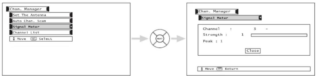
flowchart
graph LR
    A["Chan. Manager"] --> B["Set The Antenna"]
    B --> C["Auto Chan. Scan"]
    C --> D["Signal Meter"]
    D --> E["Channel List"]
    E --> F["Move Select"]
    G["Channel : 3 - Strength : 1 Peak : 1 Close"] --> H["Move SPI Return"]
Use the CURSOR PAD and the SELECT button to highlight and select "close" to exit.
NOTE: The Signal Meter will not be available (grayed out) when watching analog channels.
Channel List
This function allows you to review which channels are labeled (CH ID), which have been added to Channel Memory (SCAN), which are protected by LOCK and which are your Favorite (FAV) Channels.
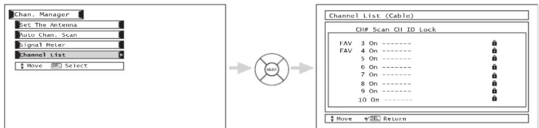
flowchart
graph LR
    A["Chan. Manager"] --> B["Set The Antenna"]
    B --> C["Auto Chan. Scan"]
    C --> D["Signal Meter"]
    D --> E["Channel List"]
    E --> F["Move Select"]
    G["Channel List (Cable)"] --> H["CII# Scan CII ID Lock"]
    H --> I["FAV 3 On ----"]
    H --> J["FAV 4 On ----"]
    H --> K["5 On ----"]
    H --> L["6 On ----"]
    H --> M["7 On ----"]
    H --> N["8 On ----"]
    H --> O["9 On ----"]
    H --> P["10 On ----"]
    Q["Move Return"] --> R
Use the CURSOR PAD to navigate the Channel List.
Press the CURSOR PAD (▲, ▼) to select On or Off on the Scan column.
Press the EXIT button to return to normal viewing.
NOTE: When a CableCARD is installed, the Channel List will be dependent on channels agreed upon by you and your cable operator.
Locks
This function will block out the picture and sound of the selected channel or video input. It can also be used to keep the TV from being viewed for a scheduled time period that you set.
The code to enter the Locks feature is a four digit access code number. The factory preset code is 0000. Use the number buttons to enter the access code.
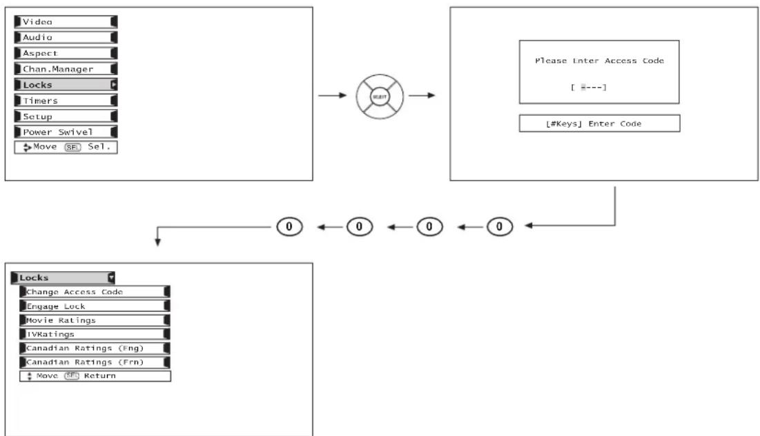
flowchart
graph TD
    A["Video"] --> B["OK"]
    C["Audio"] --> B
    D["Aspect"] --> B
    E["Chan.Manager"] --> B
    F["Locks"] --> B
    G["Timers"] --> B
    H["Setup"] --> B
    I["Power Swivel"] --> B
    J["Move SE Sel."] --> B
    K["Please Enter Access Code\n[ ---"] \n["#Keys"] Enter Code] --> L["0 ← 0 ← 0 ← 0 ←"]
    L --> M["Locks\nChange Access Code\nEngage Lock\nMovie Ratings\nIVKatings\nCanadian Ratings (Fng)\nCanadian Ratings (Frn)\nMove (FF) Return"]
Use the CURSOR PAD ▲ or ▼ to highlight function and then press the SELECT button. To change the access code number, select Change Access Code. Enter a new four digit number.
Select CHANGE ACCESS CODE to change the factory preset code (0000) to your preference.
When ENGAGE LOCK is selected, SET CHANNEL LOCK, SET INPUT LOCK, and SET FRONT PANEL LOCK can be set individually.
When SET CHANNEL LOCK is turned on, the picture and sound for the chosen channel will be blocked out.
When SET INPUT LOCK is turned on, the picture and sound for all video inputs and the picture and sound for channels 3, 4 will be blocked out.
When FRONT PANEL LOCK is turned on, all buttons on the Front Panel will be deactivated, except the Power button.
When MOVIE RATINGS is selected, you can block various types of movies and video tapes based on motion picture ratings. Picture-in-Picture will also be blocked automatically (see page 63).
When TV RATINGS is selected, various types of television programming based on a parental guide ratings will be blocked. Picture-in-Picture will also be blocked automatically (see page 64).
Use CANADIAN RATINGS to block various types of movies and television programs based on the two rating systems used in Canada that you feel may be inappropriate due to its content (see pages 65-66).
If you forget your access code, use the factory code 7777 to erase your key number. This will reset the access code number back to the factory preset 0000. Press EXIT to quit the menu.
NOTE: If MOVIE/TV Ratings Lock function settings are ON, SURF will be deactivated.
Movie Ratings
Use MOVIE RATINGS to prevent viewing of any movie that you feel may be inappropriate due to its content.

flowchart
graph LR
    A["MENU"] --> B["Switch"]
    B --> C["Locks"]
    C --> D["Change Access Code"]
    C --> E["Lengage Lock"]
    C --> F["TV Time Lock"]
    C --> G["Movie Ratings"]
    C --> H["TV Ratings"]
    C --> I["Canadian Ratings (Lng)"]
    C --> J["Canadian Ratings (+Rn)"]
    C --> K["Move (SE) Select"]
    L["Menu"] --> M["Locks"]
    M --> N["Movie Ratings"]
    N --> O["Status"]
    O --> P["Not Rated: 📄"]
    O --> Q["G: 📄"]
    O --> R["PG: 📄"]
    O --> S["PG-13: 📄"]
    O --> T["R: 📄"]
    O --> U["NC-17: 📄"]
    O --> V["X: 📄"]
    W["Move (SE) Return"] --> X
Use the CURSOR PAD ▲ or ▼ to select the MOVIE RATING category that you want to block.
Press SELECT to block the MOVIE RATING that you have selected. Once rating is selected, for example PG-13, all movies rated PG-13 and higher (R, NC-17, and X) will be blocked.
Press EXIT to quit the menu or select MOVIE RATING to return to the previous menu.
Motion Picture Ratings Chart
| G | General audiences. All ages admitted. |
| PG | Parental guidance suggested. Some material may not be suitable for children. |
| PG-13 | Parents strongly cautioned. Some material may be inappropriate for children under 13. |
| R | Restricted. Under 17 requires accompanying parent or adult guardian. |
| NC-17 | No one 17 and under admitted. |
| X | Adults only |
| NOT RATED (NR) | Contains no rating. Not Rated (NR) and Not Applicable (NA) programs. Movie has not been rated or ratings do not apply. |
NOTES:
- A movie rating is dependent upon the movie that is viewed. If the movie does not carry a rating, the TV will not block it.
- Blocking "NOT RATED (NR)" programs may block emergency programming, sports, news, public service announcements, religious programs and weather.
- If a CableCARD is installed, your cable operator may provide an Emergency Alert System (EAS) message in the event of a local or national emergency with the purpose of alerting the general public. When you receive such messages, the LCD Television will immediately tune to an EAS channel as directed by the EAS message. Please be advised that if the EAS channel is blocked using the Locks feature, you will not be able to tune to that channel.
TV Ratings
Use TV RATINGS to prevent the viewing of any TV program that you feel may be inappropriate due to its content.


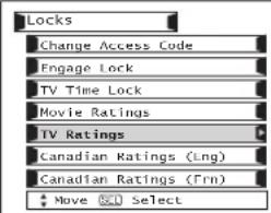
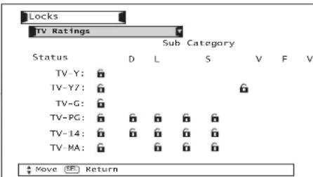
Use the CURSOR PAD ▲ or ▼ to highlight the category that you want to block.
Press select to block the TV RATINGS that you have selected.
Press EXIT to quit the menu or select TV RATINGS to return to the previous menu.
TV Parental Guide Ratings Chart
| N/A | None. |
| TV-Y | All children. The themes and elements in this program are specifically designed for a very young audience, including children from ages 2-6. |
| TV-Y7 | Directed to older children. Themes and elements in this program may include mild physical or comedic violence, or may frighten children under the age of 7. |
| TV-G | General audience. It contains little or no violence, no strong language, and little or no sexual dialogue or situations. |
| TV-PG | Parental guidance suggested. The program may contain infrequent coarse language, limited violence, some suggestive sexual dialogue and situations. |
| TV-14 | Parents strongly cautioned. This program may contain sophisticated themes, intense sexual situation, more intense violence and intensely suggestive dialogue. |
| TV-MA | Mature audiences only. This program may contain mature themes, indecent language, graphic violence, and explicit sexual content. |
| FV | Fantasy Violence |
| V | Violence |
| S | Sexual Situation |
| L | Adult Language |
| D | Sexually Suggestive Dialogue. |
NOTES:
- If you Block TV-14D, you will still permit TV MA programs; If you block TV-14DV, you will automatically block TV-MAV programs, but you will still permit TV-MALS programs. This means that the TV will block violence in TV-14 and higher (TV-MA), but not language and sex.
- TV program ratings are dependent on the broadcaster. If the program is not rated, the TV will not block it.
- If a CableCARD is installed, your cable operator may provide an Emergency Alert System (EAS) message in the event of a local or national emergency with the purpose of alerting the general public. When you receive such messages, the LCD Television will immediately tune to an EAS channel as directed by the EAS message. Please be advised that if the EAS channel is blocked using the Locks feature, you will not be able to tune to that channel.
Canadian Ratings (Eng)
Use Canadian Ratings (Eng) to block any type of movie and television program in Canada that you feel might be inappropriate in its content.

flowchart
graph LR
    A["MENU"] --> B["Locks"]
    B --> C["Change Access Code"]
    B --> D["Lngage Lock"]
    B --> E["TV Time Lock"]
    B --> F["Movie Ratings"]
    B --> G["TV Ratings"]
    B --> H["Canadian Ratings (Eng)"]
    B --> I["Canadian Ratings (Fm)"]
    B --> J["Move (SF) Select"]
    K["Locks"] --> L["Canadian Ratings (Eng)"]
    L --> M["Status"]
    M --> N["C: 📞"]
    M --> O["C8+: 📞"]
    M --> P["G: 📞"]
    M --> Q["PG: 📞"]
    M --> R["14+: 📞"]
    M --> S["18+: 📞"]
    T["Move 📄 Return"] --> U
Use the CURSOR PAD ▲ or ▼ to select the CANADIAN RATINGS (Eng) category that you want to block. Press SELECT to set the CANADIAN RATINGS (Eng) that you have selected. Once rating is selected, for example C8+, all movies and television programs rated C8+ and higher (G, PG, 14+ and 18+) will be blocked automatically. Press EXIT to quit menu.
Canadian Ratings English Chart
| C | Programming intended for children under age 8 - Violence Guidelines; Careful attention is paid to themes, which could threaten children's sense of security and well-being. There will be no realistic scenes of violence. Depictions of aggressive behaviour will be infrequent and limited to portrayals that are clearly imaginary, comedic or unrealistic in nature. Other Content Guidelines: There will be no offensive language, nudity or sexual content. |
| C8+ | Programming generally considered acceptable for children 8 years and over to watch on their own - Violence Guidelines: Violence will not be portrayed as the preferred, acceptable, or only way to resolve conflict; or encourage children to imitate dangerous acts which they may see on television. Any realistic depictions of violence will be infrequent, discreet, of low intensity and will show the consequences of the acts. Other Content Guidelines: There will be no profanity, nudity or sexual content. |
| G | General Audience - Violence Guidelines: Will contain very little violence, either physical or verbal or emotional. Will be sensitive to themes which could frighten a younger child, will not depict realistic scenes of violence which minimize or gloss over the effects of violent acts. Other Content Guidelines: There may be some inoffensive slang, no profanity and no nudity. |
| PG | Parental Guidance - Programming intended for a general audience but which may not be suitable for younger children. Parents may consider some content inappropriate for unsupervised viewing by children ages 8-13. Violence Guidelines: Depictions of conflict and/or aggression will be limited and moderate; may include physical, fantasy, or supernatural violence. Other Content Guidelines: May contain infrequent mild profanity, or mildly suggestive language. Could also contain brief scenes of nudity. |
| 14+ | Programming contains themes or content which may not be suitable for viewers under the age of 14 - Parents are strongly cautioned to exercise discretion in permitting viewing by pre-teens and early teens. Violence Guidelines: May contain intense scenes of violence. Could deal with mature themes and societal issues in a realistic fashion. Other Content Guidelines: May contain scenes of nudity and/or sexual activity. There could be frequent use of profanity. |
| 18+ | Adult - Violence Guidelines: May contain violence integral to the development of the plot, character or theme, intended for adult audiences. Other Content Guidelines: May contain graphic language and explicit portrayals of nudity and/or sex. |
Canadian Ratings (Frn)
Use CANADIAN RATINGS (FRN) to block Canadian French programs according to various program ratings that you feel might be inappropriate in its content.


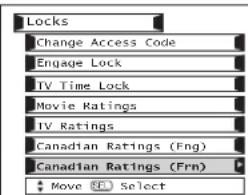
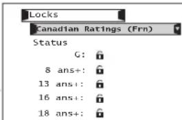
Move SEL Return
Use the CURSOR PAD ▲ or ▼ to highlight the category that you want to block.
Press SELECT to set the CANADIAN RATINGS (FRN) that you have selected.
Once rating is selected, for example 8 ans+, all movies and television programs rated 8 ans+ and higher will be automatically blocked.
Press EXIT to quit menu or select the CURSOR PAD ◀ to return to the previous menu.
Canadian Ratings French Chart
| G | General - Programming intended for audiences of all ages. Contains no violence, or the violence content is minimal or is depicted appropriately with humor or caricature or in an unrealistic manner. |
| 8 ans + | 8 + General - Not recommended for young children - Programming intended for a broad audience but contains light or occasional violence that could disturb young children. Viewing with an adult is therefore recommended for young children (under the age of 8) who cannot differentiate between real and imaginary portrayals. |
| 13 ans + | Programming may not be suitable for children under the age of 13 - Contains either a few violent scenes or one or more sufficiently violent scenes to affect them. Viewing with an adult is therefore strongly recommended for children under 13. |
| 16 ans + | Programming is not suitable for children under the age of 16 - Contains frequent scenes of violence or intense violence. |
| 18 ans + | Programming restricted to adults - Contains constant violence or scenes of extreme violence. |
Timers
Select Timers to set your Clock, Sleep Timer, Event Timer and Day/Night Timer Recordings.
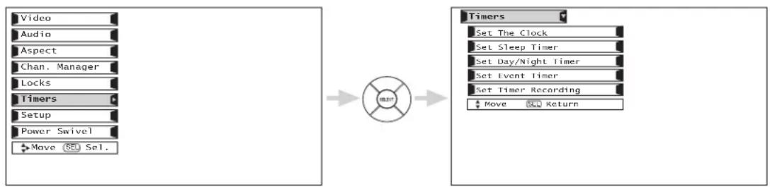
flowchart
graph LR
    A["Video"] --> B["Audio"]
    B --> C["Aspect"]
    C --> D["Chan. Manager"]
    D --> E["Locks"]
    E --> F["Timers"]
    F --> G["Setup"]
    G --> H["Power Swivel"]
    H --> I["Move Sel."]

    J["Timer"] --> K["Set The Clock"]
    K --> L["Set Sleep Timer"]
    L --> M["Set Day/Night Timer"]
    M --> N["Set Event Timer"]
    N --> O["Set Timer Recording"]
    O --> P["Move Return"]
Set The Clock
The Clock must be adjusted before you can use the "Set Event Timer" or Day/Night Timer" feature.
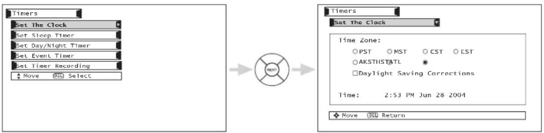
flowchart
graph LR
    A[" Timers "] --> B[" Set The Clock "]
    B --> C[" Set Sleep Timer "]
    C --> D[" Set Day/Night Timer "]
    D --> E[" Set Event Timer "]
    E --> F[" Set Timer Recording "]
    F --> G[" Move Select "]
    H[" Timers "] --> I[" Set The Clock "]
    I --> J[" Time Zone: PST MST CST CST AKSTHSTATL Daylight Saving Corrections Time: 2:53 PM Jun 28 2004"]
    J --> K[" Move Return "]
Use the CURSOR PAD ▲, ▼, ◀, ► to highlight the chosen Time Zone settings.
Press the SELECT button to select.
If you observe daylight savings, use CURSOR PAD to highlight "Daylight Saving Correction" and press the SELECT button to select.
Use the CURSOR PAD ▲, ▼, ◀, ▶ to highlight the current time (hour and minute), AM or PM, Month, Day, and Year.
Use the CURSOR PAD ▲, ▼ to adjust settings.
Press the SELECT button to set the Time and Date.
Press EXIT to quit the menu.
NOTES: When "Daylight Saving Correction" is checked "√", the TV will automatically calculate the clock adjustment for Daylight Saving.
Set Sleep Timer
Select this feature to set your Sleep Timer from 30 minutes to 3 hours (30 minute increments).
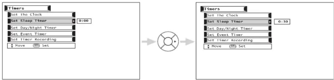
Press the CURSOR PAD ▶ repeatedly to set your Timer from 0:00, 0:30, 1:00, 1:30, 2:00, 2:30 and 3:00.
Set Day/Night Timer
Select this feature to activate and set your TV's Day/Night Picture Mode automatically.
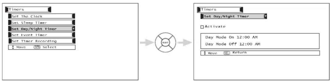
flowchart
graph LR
    A["Timers"] --> B["Set The Clock"]
    B --> C["Set Sleep Timer"]
    C --> D["Set Day/Night Timer"]
    D --> E["Set Event Timer"]
    E --> F["Set Timer Recording"]
    F --> G["Move (S) Select"]
    H["Timers"] --> I["Set Day/Night Timer"]
    I --> J["Activate"]
    J --> K["Day Mode On 12:00 AM"]
    J --> L["Day Mode Off 12:00 AM"]
    L --> M["Move Return"]
Use the CURSOR PADS and the SELECT button to activate the Day/Night Timer. Use the CURSOR PADS to select Day Mode On and to set it's timer. Use the CURSOR PADS to select Day Mode Off and to set it's timer.
Set Event Timer
This function will automatically operate the TV viewing reservation of a program. If the clock is not set, you can not use this function and the screen below will appear. The message on the screen will disappear after 3 seconds, then the screen automatically goes to the clock setup mode (see page 67).
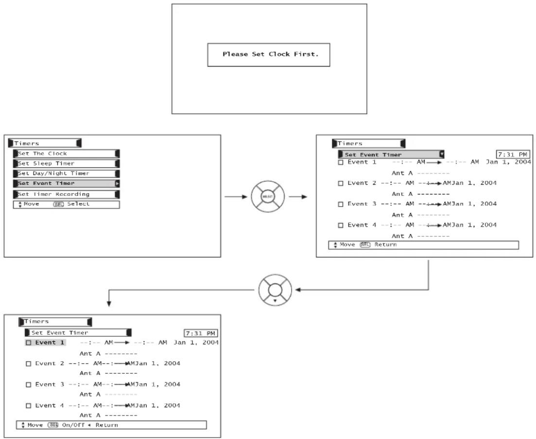
flowchart
graph TD
    A["Please Set Clock First."] --> B["Timing Select"]
    B --> C["Event 1: AM→AM Jan 1, 2004 Ant A ----"]
    B --> D["Event 2: AM→AMJan 1, 2004 Ant A ----"]
    B --> E["Event 3: AM→AMJan 1, 2004 Ant A ----"]
    B --> F["Event 4: AM→AMJan 1, 2004 Ant A ----"]
    B --> G["Move ON/OFF Return"]
    C --> H["Time Window"]
    D --> H
    E --> H
    F --> H
    G --> H
Use CURSOR PAD ▲, ▼ to highlight Event 1, Event 2, Event 3, Event 4 and then press the SELECT button to select.
Use CURSOR PAD ▶, ▲, ▼ to highlight and select START TIME Hour/Minute.
Use CURSOR PAD ▶, ▲, ▼ to highlight and select START TIME AM/PM.
Use CURSOR PAD ▶, ▲, ▼ to highlight and select FINISH TIME Hour/Minute.
Use CURSOR PAD ▶, ▲, ▼ to highlight and select FINISH TIME AM/PM.
Use CURSOR PAD ▶ to highlight the MONTH.
Use CURSOR PAD ▲ to select a MONTH or CURSOR PAD ▼ to select Daily, Weekly - Sunday to Monday. Use CURSOR PAD ◀ to return to MONTH.
Use CURSOR PAD ▶, ▲, ▼ to highlight and select the DAY of the MONTH.
Use CURSOR PAD ▶, ▲, ▼ to highlight and select the YEAR.
Use CURSOR PAD ▶, ▲, ▼ to highlight and select Ant A or Ant B.
Use CURSOR PAD ▶, ▲, ▼ or NUMBER buttons to set the channel the TV will tune into.
A “√” in the box means it is enabled.
NOTE:
- When the INFO button is pressed, the Event Timer Icon will only display the current date ON/OFF timer.
- The Off Timer will only activate if the TV was turned on by the On Timer and no channel selection was made after this time. If you change the channel after the On Timer has been activated, the Off Timer will deactivate.
- If no remote control button is pressed after viewing reservation is activated, the TV will automatically turn off after three hours. Therefore, do not Set Event Timer for more than three hours if you do not plan to control your television with the remote control.

CAUTION: Do not use your TV as a deterrent when away from home by using the On and Off Timers. For safety, the TV should be turned off when you are away from home.
Set Timer Recording
Select this feature to set and record digital channels using your device connected to the IEEE 1394 jacks (ex. D-VHS).
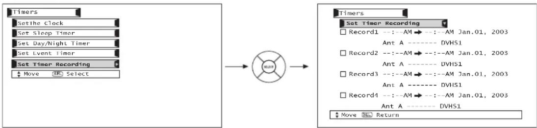
flowchart
graph LR
    A["Set the Clock"] --> B["Set Sleep Timer"]
    B --> C["Set Day/Night Timer"]
    C --> D["Set Event Timer"]
    D --> E["Set Timer Recording"]
    E --> F["Move Select"]
    G["Set Timer Recording"] --> H["Record1 --: AM --> : -AM Jan.01, 2003"]
    H --> I["Ant A ---- DVHS1"]
    I --> J["Record2 --: AM --> : -AM Jan.01, 2003"]
    J --> K["Ant A ---- DVHS1"]
    K --> L["Record3 --: AM --> : -AM Jan.01, 2003"]
    L --> M["Ant A ---- DVHS1"]
    M --> N["Record4 --: AM --> : -AM Jan.01, 2003"]
    N --> O["Ant A ---- DVHS1"]
    O --> P["Move Return"]
Use CURSOR PAD ▲, ▼ to highlight Record 1, Record 2, Record 3 and then press CURSOR PAD to select.
Use CURSOR PAD ▶, ▲, ▼ to highlight and select START TIME Hour/Minute.
Use CURSOR PAD ▶, ▲, ▼ to highlight and select START TIME AM/PM.
Use CURSOR PAD ▶, ▲, ▼ to highlight and select FINISH TIME Hour/Minute.
Use CURSOR PAD ▶, ▲, ▼ to highlight and select FINISH TIME AM/PM.
Use CURSOR PAD ▶ to highlight the MONTH.
Use CURSOR PAD ▲ to select a MONTH or CURSOR PAD ▼ to select Daily, Weekly - Sunday to Monday. Use CURSOR PAD ▲ to return to MONTH.
Use CURSOR PAD ▶, ▲, ▼ to highlight and select the DAY of the MONTH.
Use CURSOR PAD ▶, ▲, ▼ to highlight and select the YEAR.
Use CURSOR PAD ▶, ▲, ▼ to highlight and select ANT C channel # to be recorded.
Use CURSOR PAD ▶, ▲, ▼ to highlight and select 1394 Device to be used.
Press the SELECT button to return and highlight Record 1.
A “√” in the box means it is enabled.
NOTES: 1. Set the Time and connect the IEEE1394 devices before using this feature.
- The Timer Recording has priority over the Event Timer. If the Timer Recording is set at the same time as the Event Timer or overlaps with each other, the TV will only perform the function of the Timer Recording.
Setup
Select SETUP when setting up your TV for the first time. Use the CURSOR PAD ▲ or ▼ on the remote to highlight the function desired.
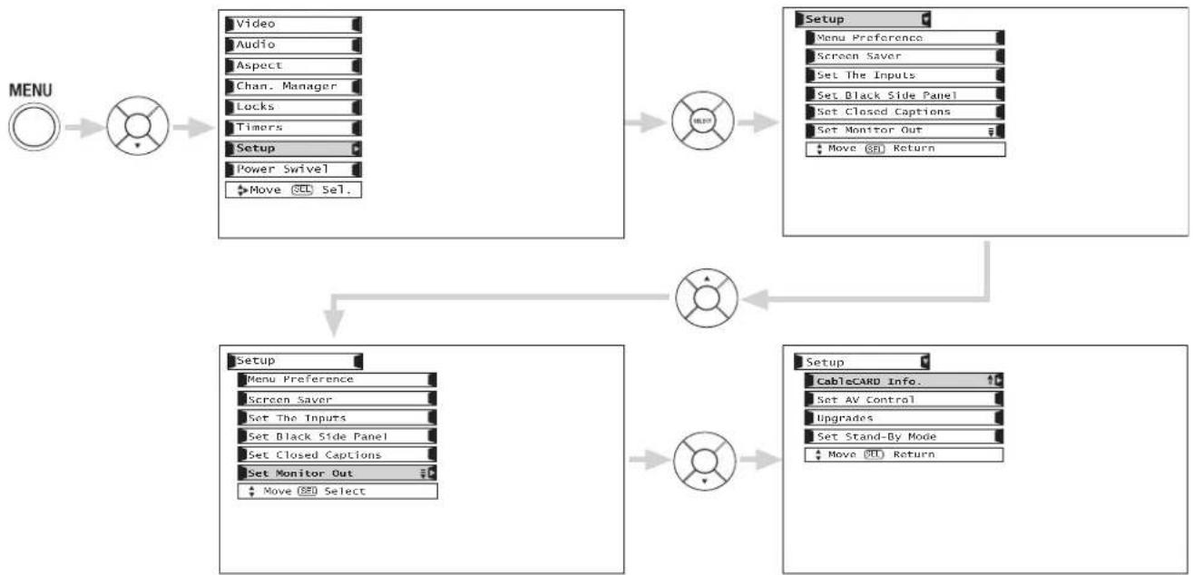
flowchart
graph TD
    A["MENU"] --> B["Menu"]
    B --> C["Video"]
    C --> D["Audio"]
    D --> E["Aspect"]
    E --> F["Chan. Manager"]
    F --> G["Locks"]
    G --> H["Timors"]
    H --> I["Setup"]
    I --> J["Power Swivel"]
    J --> K["Move Select"]
    K --> L["Setup"]
    L --> M["Menu Preference"]
    M --> N["Screen Saver"]
    N --> O["Set The Inputs"]
    O --> P["Set Black Side Panel"]
    P --> Q["Set Closed Captions"]
    Q --> R["Set Monitor Out"]
    R --> S["Move Select"]
    S --> T["Setup"]
    T --> U["CableCARD Info."]
    U --> V["Set AV Control"]
    V --> W["Upgrades"]
    W --> X["Set Stand-By Mode"]
    X --> Y["Move Select"]
    Y --> Z["Setup"]
Use CURSOR PAD (▲,▼,◀,▶) to select the sub-menu of your choice.
Press the SELECT button to select.
Menu Preference
This feature will allow you to select any one of three different languages for all on-screen displays.
MENU


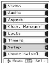

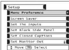

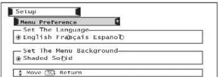
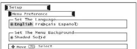
Use CURSOR PAD ◀, ▶ to highlight the language of your choice.
Press SELECT to select the highlighted language.
Press EXIT to quit the menu.
Menu Background
This function allows you to choose from two menu backgrounds.
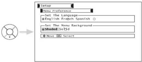
Use CURSOR PAD ◀, ▶ to highlight SET THE MENU BACKGROUND (shaded or solid), and the SELECT button to select the setting. Press EXIT to quit the menu.
Select SOLID and background is visible (no picture can be seen behind menu screen), select SHADED and a light background is visible.
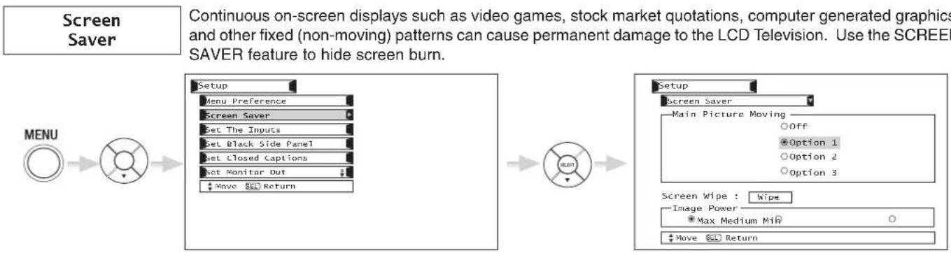
flowchart
graph LR
    A["Menu"] --> B["Setup"]
    B --> C["Main Picture Moving"]
    C --> D["Main Picture Moving"]
    D --> E["Main Picture Moving"]
    E --> F["Main Picture Moving"]
    F --> G["Main Picture Moving"]
    G --> H["Main Picture Moving"]
    H --> I["Main Picture Moving"]
    I --> J["Main Picture Moving"]
    J --> K["Main Picture Moving"]
    K --> L["Main Picture Moving"]
    L --> M["Main Picture Moving"]
    M --> N["Main Picture Moving"]
    N --> O["Main Picture Moving"]
    O --> P["Main Picture Moving"]
    P --> Q["Main Picture Moving"]
    Q --> R["Main Picture Moving"]
    R --> S["Main Picture Moving"]
    S --> T["Main Picture Moving"]
    T --> U["Main Picture Moving"]
    U --> V["Main Picture Moving"]
    V --> W["Main Picture Moving"]
    W --> X["Main Picture Moving"]
    X --> Y["Main Picture Moving"]
    Y --> Z["Main Picture Moving"]
    Z --> AA["Main Picture Moving"]
    AA --> AB["Main Picture Moving"]
    AB --> AC["Main Picture Moving"]
    AC --> AD["Main Picture Moving"]
    AD --> AE["Main Picture Moving"]
    AE --> AF["Main Picture Moving"]
    AF --> AG["Main Picture Moving"]
    AG --> AH["Main Picture Moving"]
    AH --> AI["Main Picture Moving"]
    AI --> AJ["Main Picture Moving"]
    AJ --> AK["Main Picture Moving"]
    AK --> AL["Main Picture Moving"]
    AL --> AM["Main Picture Moving"]
    AM --> AN["Main Picture Moving"]
    AN --> AO["Main Picture Moving"]
    AO --> AP["Main Picture Moving"]
    AP --> AQ["Main Picture Moving"]
    AQ --> AR["Main Picture Moving"]
    AR --> AS["Main Picture Moving"]
    AS --> AT["Main Picture Moving"]
    AT --> AU["Main Picture Moving"]
    AU --> AV["Main Picture Moving"]
    AV --> AW["Main Picture Moving"]
    AW --> AX["Main Picture Moving"]
    AX --> AY["Main Picture Moving"]
Use CURSOR PAD▲, ▼ to highlight Screen Saver's Main Picture Moving options. Press down on CURSOR PAD to select and EXIT to quit.
Option 1
The whole picture will shift every 20 minutes by two pixels.
Option 2
The whole picture will shift every 40 minutes by two pixels.
Option 3
The whole picture will shift every 60 minutes by two pixels.
Screen Wipe
If pattern mark occurs, use Screen Wipe (White Field Signal) for at least 10 minutes to refresh any damage that may have occurred from a pattern mark. Screen Wipe can resolve pattern mark to a certain degree, if caution is not used, permanent damage may occur. Press the EXIT button to return to normal viewing.
Screen Saver Picture's Movement
flowchart
graph TD
    A[" "] --> B[" "]
    C[" "] --> D[" "]
    E[" "] --> F[" "]
    G[" "] --> H[" "]
    B --> D
    D --> F
    F --> H
    H --> I["Image Power"]
This function allows you to choose Power Consumption reduction.
Set The Inputs
Use this feature to give a name to any of the five video inputs.
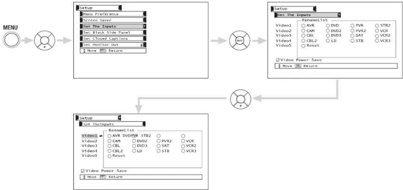
flowchart
graph TD
    A["MENU"] --> B["Menu"]
    B --> C["Setup"]
    C --> D["Set The Inputs"]
    D --> E["Setup"]
    E --> F["Set The Inputs"]
    F --> G["Video1 AVR DVD PVR STB2"]
    F --> H["Video2 CAM DVD2 PVR2 VCR"]
    F --> I["Video3 CBL DVD3 SAT VCR2"]
    F --> J["Video4 CBL2 LD STB VCR3"]
    F --> K["Video5 Reset"]
    L["Video Power Save"] --> M["Move 3D Return"]
    N["Setup"] --> O["Setup"]
    O --> P["Setup"]
    P --> Q["Setup"]
    Q --> R["Setup"]
    R --> S["Setup"]
    S --> T["Setup"]
    T --> U["Setup"]
Press CURSOR PAD ▲, ▼ to highlight the name of the video inputs. Press the SELECT button to select desired input name.
Select RESET to set video names to original factory preset condition.
NOTE: The video input name will be displayed only when video input is displayed as main picture.
Video Power Save
Use this feature to reduce power consumption for video input when there is no video input signal. In RGB mode, this feature will always be on.
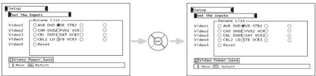
flowchart
graph LR
    A["Setup"] --> B["Set The Inputs"]
    B --> C["Rename List"]
    C --> D["Video1: AVR DVD PVR STR2 ○ ○"]
    C --> E["Video2: CAM DVD2 PVR2 VCR ○ ○"]
    C --> F["Video3: CBL DVD3 SAT VCR2 ○ ○"]
    C --> G["Video4: CBL2 LD STB VCR3 ○ ○"]
    C --> H["Video5: Reset"]
    I["Video Power Save"] --> J["Move CLL Return"]
    K["Setup"] --> L["Set The Inputs"]
    L --> M["Rename List"]
    M --> N["Video1: AVR DVD PVR STR2 ○ ○"]
    M --> O["Video2: CAM DVD2 PVR2 VCR ○ ○"]
    M --> P["Video3: CBL DVD3 SAT VCR2 ○ ○"]
    M --> Q["Video4: CBL2 LD STB VCR3 ○ ○"]
    M --> R["Video5: Reset"]
    S["Video Power Save"] --> T["Move CLL Return"]
Press CURSOR PAD ▼ to highlight VIDEO POWER SAVE. Press the SELECT button to select.
Video 2 Auto Link
Use this function to automatically turn the TV on and tune to Video 2 when it detects a video signal to input 2.
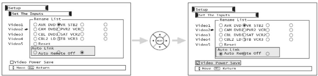
Use CURSOR PAD ▲, ▼, ◀, ▶ then press the SELECT button to change AUTO LINK setting.
When AUTO is selected, the TV will turn on and switch to Video2 automatically, when the Video2 input device is turned on. This is convenient when you want to watch a movie with your VCR, laserdisc player, or DVD player.
When REMOTE is selected, the TV will turn on and switch to Video2 automatically when the Video2 input device is turned on (VCR, laserdisc, or DVD) and any of the buttons on your remote control is pressed.
Select Off to disable this function.
Press EXIT to quit the menu.
NOTES: 1. Once the TV has been turned on using the AUTO LINK feature, it must be reset before AUTO LINK is used again. To do this, turn your VCR, laserdisc, or DVD player OFF. This feature is now reset and will turn on your TV as described above.
2. When using REMOTE mode, any remote control button will substitute for your video input device play button. However, intended operation is for use with your VCR, laserdisc, or DVD play button.
3. If no remote control button is pressed after the TV is turned on by AUTO LINK, the TV will automatically turn off after three hours.
Set Black Side Panel
The BLACK SIDE PANEL function turns the gray side bars on/off when watching 4:3 signals in Standard mode.
| Setting Signal | Off On Auto 1 | Auto 2 | Recommended Aspect | |
| NTSC/480i/480pAspect: 4:3 standard | Gray | Black Gray Gray | 4x3 Expanded | |
| 1080i (4x3 source)Aspect: 16:9 standard | Black | Black Gray Gray | 4x3 Expanded | |
| 1080i (4x3 source with logo on cornerAspect: 16:9 standard | Black | Black Black Gray | 4x3 Expanded |
NOTES: 1. To prevent screen burn when watching 4:3 signal, turn off the BLACK SIDE PANEL. It is recommended to watch 4:3 signal with gray side bar.
2. Depending on received signals, some images and Closed Caption displays may be missing when the Black Side Panel is set to Auto 1 or Auto 2.
Set Closed Caption
Closed Captions are the dialogue, narration, and/or sound effects of a television program or home video which are displayed on the TV screen. Your local TV program guide denotes these programs as cc or

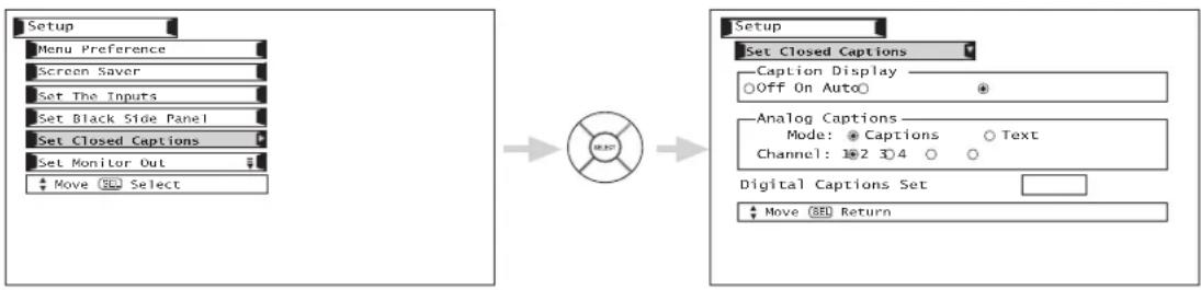
Caption Display: On/Off will turn the display on or off.
Auto will turn the display on when Mute/Soft Mute is on.
Caption Mode: Captions is for the program you are viewing.
Text is for additional information such as news reports or a TV program guide. This information covers the entire screen and viewing the TV program is not possible. Text may not be available with every program.
CHANNEL: 1 is used for the primary language (usually English).
2 is sometimes used for a second language (may vary by region).
3 is sometimes used for a third language (may vary by region).
4 is sometimes used for a fourth language (may vary by region).
Use the CURSOR PAD ▲, ▼, ◀, ▶ to highlight the function to change then press the SELECT button to select the function.
Press EXIT to quit menu or the CURSOR PAD ◀ to return to previous menu.
Digital Captions: Set captions for digital programs. This function will help choose and set available language, font, size and style of digital captions.
![Setup Set Closed Captions Caption Display Off On Auto Analog Captions Mode: Captions Text Channel: 2 8 4 0 Digital Captions SET Move 35 Return Digital Caption Font Style Service: [1 2 3 4 5 6] Language: [Unknown ] Font : [Default 1 2 3 4 5 6 7 8] Size : Standard Small Large Style : Standard High Visibility [HITACHI] Move 35 Return](/content/2026/06/1147412/images/8194d5e1b4febb84f21675b09e813dc76d3e007483aae860357fc2dfa62fb9f2.jpg)
Use the CURSOR PAD ▲, ▼, ◀, ▶ to highlight desired Digital Captions feature.
Press the SELECT button to select desired feature.
Press EXIT to quit menu or the CURSOR PAD ◀ to return to previous menu.
NOTES:
- Depending on the source, some types of digital closed captions may not work with this TV.
- CAPTION DISPLAY will not work when viewing a 480p, 720p, or 1080i input via the COMPONENT: Y-P B P R inputs.
- When PIP Surf is on, Closed Caption will not work.
- Digital Captions Font Style are sometimes different from the Font Style of Analog Captions.
- Closed Caption and Digital Captions availability and content depends on the broadcaster. Closed Caption is available when Closed Caption icon is displayed on screen.
- Digital Captions will not be available (grayed out) when using analog channels.
Set Monitor Out
This feature will select the source of the Monitor Output.
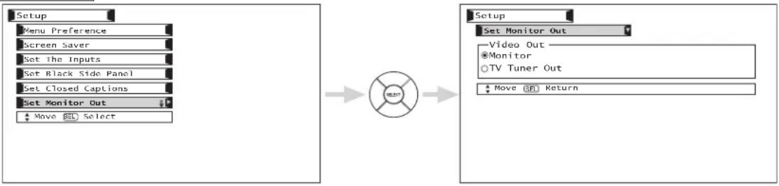
flowchart
graph LR
    A["Setup"] --> B["Menu Preference"]
    B --> C["Screen Saver"]
    C --> D["Set The Inputs"]
    D --> E["Set Black Side Panel"]
    E --> F["Set Closed Captions"]
    F --> G["Set Monitor Out"]
    G --> H["Move SEL Select"]
    I["Setup"] --> J["Set Monitor Out"]
    J --> K["Video Out"]
    K --> L["Monitor"]
    L --> M["TV Tuner Out"]
    M --> N["Move SEL Return"]
Monitor- Select Monitor to output the audio and video signals of the chosen input source (ANT A, ANT B, VID1-VID5) to a VCR or other A/V device.
TV Tuner Out- Select TV Tuner Out to output the audio and video signals of the last watched Antenna Source (ANT A, ANT B).
Use CURSOR PAD ▲, ▼ to highlight the function to change then press the SELECT button to select the function.
Press EXIT to quit menu or CURSOR PAD ◀ to return to previous menu.
CableCARD Info
Select this feature to access your CableCARD ID and HOST ID. Please have this information ready when you call your cable operator (see also page 13).
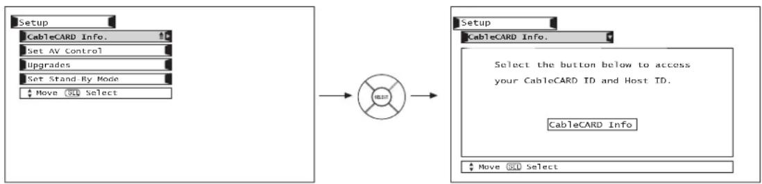
flowchart
graph LR
    A["Setup"] --> B["CableCARD Info."]
    B --> C["Set AV Control"]
    C --> D["Upgrades"]
    D --> E["Set Stand-By Mode"]
    E --> F["Move OK Select"]
    G["Target Button"] --> H["Setup"]
    H --> I["CableCARD Info."]
    I --> J["Select the button below to access your CableCARD ID and Host ID."]
    J --> K["CableCARD Info"]
    L["Move OK Select"] --> M["End"]
Set AV Control
This feature will select the AV Control feature. Set this feature if you want to control some of the TV functions from an external home control system.
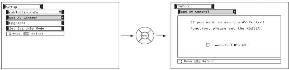
flowchart
graph LR
    A["Setup"] --> B["CableCARD Info."]
    B --> C["Set AV Control"]
    C --> D["Upgrades"]
    D --> E["Set Stand-By Mode"]
    E --> F["Move Select"]
    G["User"] --> H["Setup"]
    H --> I["Set AV Control"]
    I --> J["If you want to use the AV Control function, please set the RS232C."]
    J --> K["Connected RS232C"]
    L["Move Return"] --> M["User"]
Use the CURSOR PADS and the SELECT button to check the Connected RS232C box.
NOTE: For use with third party home Audio/Video control systems which are commercially available. Please see your dealer regarding these “non Hitachi” home control systems.
Upgrades
It shows software information and easy upgrade procedure. This function allows the TV software to be upgraded by using a flash card (MMC Card). If a future software upgrade is required for your TV, Hitachi will notify and provide you with a flash card. In order to receive written notification and the flash card, please complete and return the warranty card.
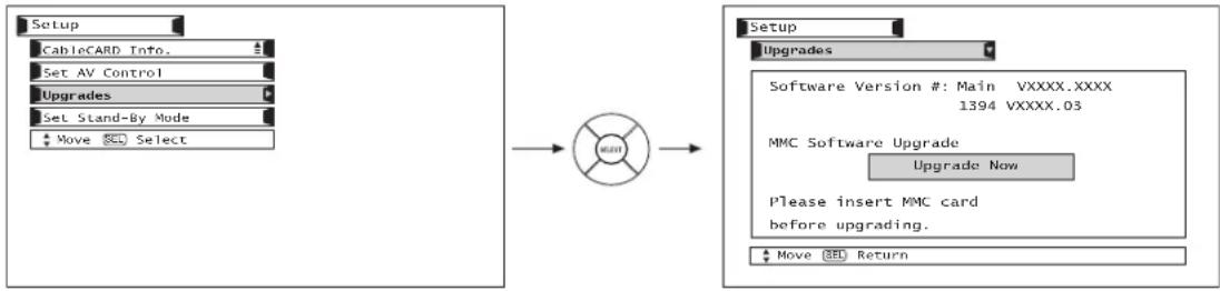
flowchart
graph LR
    A["Setup"] --> B["CableCARD Info."]
    B --> C["Set AV Control"]
    C --> D["Upgrades"]
    D --> E["Set Stand-By Mode"]
    E --> F["Move SEL Select"]
    G["Setup"] --> H["Upgrades"]
    H --> I["Software Version #: Main VXXXX.XXXX 1394 VXXXX.03"]
    I --> J["MMC Software Upgrade Upgrade Now"]
    J --> K["Please insert MMC card before upgrading."]
    K --> L["Move SEL Return"]
Insert MMC card, then press the CURSOR PAD ▲, ▼ to highlight "Upgrade Now". Press the SELECT button to select and start upgrading.
NOTE: Any power interruption during the upgrade process will cancel the upgrade. When this happens, repeat the upgrade procedure.
Set Stand-By Mode
This function sets the IEEE1394 in Stand-By Mode to ON or OFF. Certain digital devices have a power save feature, in which the device automatically powers OFF when not in use (sleep mode). Only by setting the IEEE1394 function in Stand-By mode to ON, will the TV be able to control a device that is in sleep mode.
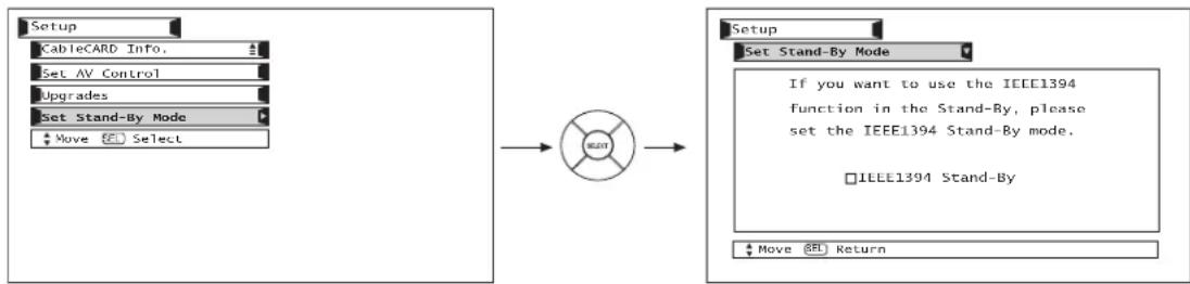
flowchart
graph LR
    A["Setup"] --> B["CableCARD Info."]
    B --> C["Set AV Control"]
    C --> D["Upgrades"]
    D --> E["Set Stand-By Mode"]
    E --> F["Move Select"]
    G["Start"] --> H["Setup"]
    H --> I["Set Stand-By Mode"]
    I --> J["If you want to use the IEEE1394 function in the Stand-By, please set the IEEE1394 Stand-By mode."]
    J --> K["IEEE1394 Stand-By"]
    L["Move Return"] --> M["End"]
NOTE: By turning ON the IEEE1394 function, your TV set will no longer be set for power saving Stand-By mode. The IEEE1394 Stand-By function must be set to OFF to return your TV set to the power saving Stand-By mode.
Power Swivel
This feature controls the motorized stand. It allows the customer to turn the LCD display left or right using the remote control.
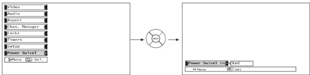
flowchart
graph LR
    A["Video"] --> C["Control Unit"]
    B["Audio"] --> C
    D["Aspect"] --> C
    E["Chan. Manager"] --> C
    F["Locks"] --> C
    G["Timers"] --> C
    H["Setup"] --> C
    I["Power Swivel"] --> C
    J["Move SCL Sel."] --> C
    K["Power Swivel Unlocked"] --> L["Move BB Set"]
Exit OSD menu system before controlling the motorized stand.
Use CURSOR PAD ▶ to rotate the TV to the right.
Use CURSOR PAD ◀ to rotate the TV to the left.
Release the CURSOR PAD to stop rotation.
NOTES: 1. The Power Swivel has a maximum turning radius of 30^ (left and right).
- Do not place any objects on the path of the monitor when using the power swivel feature.
- Before using the power swivel feature, please make sure that the path of the monitor is clear of any fingers, hands or any other body parts to avoid causing injury.
- When the Picture-in-Picture (PIP) or Freeze mode is ON, the Power Swivel is disabled.
IMPORTANT: TURN OFF THE AVC BOX, THE DISPLAY MONITOR AND THE EXTERNAL COMPONENT BEFORE CONNECTING OR DISCONNECTING ANY CABLES.
- AVC rear panel connection to an external component with an analog RGB output.
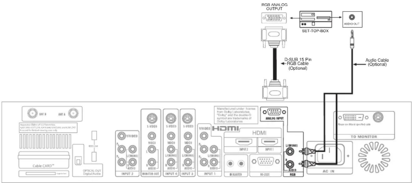
flowchart
graph TD
    A["RGB ANALOG OUTPUT"] --> B["SET-TOP-BOX"]
    B --> C["AUDIO OUT"]
    D["D-SUB 15 Pin RGB Cable (Optional)"] --> C
    E["Audio Cable (Optional)"] --> C
    F["ANT B ANT A"] --> G["Cable CARD™"]
    G --> H["OPTICAL OUT Digital Audio"]
    H --> I["INPUT 2"]
    I --> J["S-VIDEO"]
    J --> K["VIDEO"]
    K --> L["S-VIDEO"]
    L --> M["VIDEO"]
    M --> N["S-VIDEO"]
    N --> O["VIDEO"]
    O --> P["VIDEO"]
    P --> Q["VIDEO"]
    Q --> R["VIDEO"]
    R --> S["VIDEO"]
    S --> T["VIDEO"]
    T --> U["VIDEO"]
    U --> V["VIDEO"]
    V --> W["VIDEO"]
    W --> X["VIDEO"]
    X --> Y["VIDEO"]
    Y --> Z["VIDEO"]
    Z --> AA["VIDEO"]
    AA --> AB["VIDEO"]
    AB --> AC["VIDEO"]
    AC --> AD["HDMI"]
    AD --> AE["INPUT 1"]
    AE --> AF["L(MONG)"]
    AF --> AG["RGB"]
    AD --> AH["HDMI"]
    AH --> AI["INPUT 2"]
    AI --> AJ["L(MONG)"]
    AJ --> AK["RGB"]
    AH --> AL["INPUT 1"]
    AL --> AM["IR BLASTER"]
    AM --> AN["RS-232C"]
    AD --> AO["AC IN"]
    AO --> AP["TO MONITOR"]
This LCD Television can automatically detect and display the signal format below.
- RGB input signal.
This LCD Television can accept the following signal formats.
Recommended Signal List
| Signal Mode | ||||
| No. | Signal Name | Resolution | Vertical Horizontal Frequency (Hz) | Frequency (kHz) |
| 1 VESA 640 x 400 | 70.09 31.47 | |||
| 2 VGA 640 x 480 | 59.94 31.47 | |||
| 3 640 x 480 72.81 | 37.86 | |||
| 4 640 x 480 75.00 | 37.50 | |||
| 5 800 x 600 56.25 | 35.16 | |||
| 6 800 x 600 60.32 | 37.88 | |||
| 7 VESA 800 x 600 | 72.19 48.08 | |||
| 8 800 x 600 75.00 | 46.88 | |||
| 9 1024 x 768 60.00 | 48.36 | |||
| 10 1024 x 768 70.07 | 56.48 | |||
| 11 1024 x 768 75.03 | 60.02 | |||
| 12 | 1280 x 1024 | 60.02 63.98 | ||
| 13 | 1280 x 1024 | 75.03 79.98 | ||
| 14 | 1080i 1080 | 59.94 33.72 | ||
| 15 | 720p | 720 | 59.94 44.96 | |
| 16 | 480p | 480 | 59.94 31.47 | |
NOTE: 1. Dots correspond to the true resolution in Real Mode of aspect ratio, when you select VGA 640 x 480 signal from the table above. (One dot corresponds to one pixel).
2. Always reset AUTO ADJUST feature when setting new display setting or when changing to a new computer (see page 85).
- The new setting (horizontal position, vertical position, clock, and phase) of the signal will be stored. The monitor can store up to 13 settings in addition to the 15 pre-set signal timing. Any additional new settings (more than 15) will over-write the first user's setting, second setting and so on.
- Operation in RGB mode in relation to TV functions are shown below.
| No. | tem Operation | |
| 1 | Video Control Contrast and brightness work separately, however, other picture controls are not available. | |
| 2 | AV Net Available. | |
| 3 | Audio Settings Not available. | |
| 4 | Closed Caption Not available. | |
| 5 | Clock Clock indication is shown. | |
| 6 | Monitor Out Both picture and audio are not available. | |
| 7 | Lock Not available. | |
| 8 | Auto Link Not Available. | |
- Other signal formats may not be displayed correctly. Use AUTO ADJUST to automatically adjust the horizontal position, vertical position, clock, and phase. We recommend you use a signal, which has more than 50% of amplitude of white area at each corner of the picture, when performing Auto Adjustment. It may not work correctly with dark picture (see page 85).
- Input signal level.
| SYNC TTL level H/V separate signal | |
| RGB INPUT 0.7Vpp/1.0Vpp |
NOTE: Interlaced signal is not available.
- RGB input signal will not appear at all when receiving a signal which is not supported by this product. If the setting is wrong, the Display Monitor will display:
NO SYNC. SIGNAL
INVALID SCAN FREQ.
Without sync Either horizontal or vertical
POWER SAVING mode will come on after 10 seconds.
frequency is inappropriate or out of range.
INVALID SCAN FREQ. will disappear after 60 seconds.
NOTE: 1. If the Display Monitor cannot display a signal, please try AUTO ADJUST to display the signal. This is used to initialize the MultiScan Converter.
2. Not all signals have AUTO ADJUST feature (see page 85).
3. Set-Top-Box and DVD player input signal does not have AUTO ADJUST feature.
- Press the INPUTS button, then use the CURSOR PAD and SELECT button on the remote control to display the different features in RGB MODE.
- Press EXIT on the remote control to quickly exit from a menu.
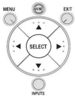
flowchart
graph TD
    A["SELECT"] --> B["AV ME"]
    A --> C["EXIT"]
    A --> D["INPUTS"]
    A --> E["MENU"]
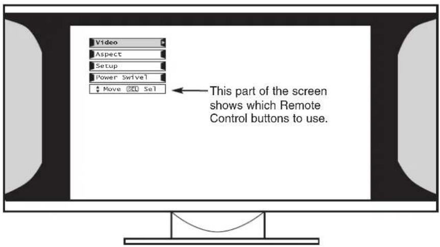
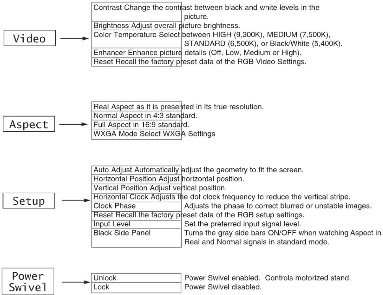
flowchart
graph TD
    A["Video"] --> B["Contrast Change the contrast"]
    B --> C["Brightness Adjust overall picture brightness"]
    B --> D["Color Temperature Select between HIGH (9,300K), MEDIUM (7,500K), STANDARD (6,500K), or Black/White (5,400K). details (Off, Low, Medium or High)."]
    B --> E["Enhancer Enhance picture Reset Recall the factory preset data of the RGB Video Settings."]
    A --> F["Aspect"]
    F --> G["Real Aspect as it is presented in its true resolution."]
    F --> H["Normal Aspect in 4:3 standard."]
    F --> I["Full Aspect in 16:9 standard."]
    F --> J["WXGA Mode Select WXGA Settings"]
    K["Setup"] --> L["Auto Adjust Automatically adjust the geometry to fit the screen."]
    K --> M["Horizontal Position Adjust horizontal position."]
    K --> N["Vertical Position Adjust vertical position."]
    K --> O["Horizontal Clock Adjusts the dot clock frequency to reduce the vertical stripe."]
    K --> P["Clock Phase"]
    K --> Q["Reset Recall the factory preset data of the RGB setup settings."]
    K --> R["Input Level"]
    K --> S["Black Side Panel"]
    K --> T["Turns the gray side bars ON/OFF when watching Aspect in Real and Normal signals in standard mode."]
    U["Power Swivel"] --> V["Unlock"]
    U --> W["Lock"]
    U --> X["Power Swivel enabled. Controls motorized stand. Power Swivel disabled."]
VIDEO ADJUSTMENTS
The following adjustments are independent of the TV mode:
- Press MENU in RGB mode for on screen display.
- Press CURSOR PAD ▲ or ▼ to highlight the item to be adjusted.
- Press SELECT to select the highlighted item.
This feature allows you to adjust the contrast in RGB mode.
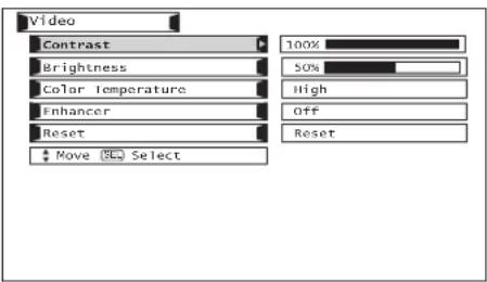
Use CURSOR PAD ◀ or ▶ to adjust contrast. Press MENU button to return to RGB MODE MENU and EXIT to quit.
NOTES: 1. Contrast can be set up to 110% if CURSOR PAD ▶ is pressed and held for more than 3 seconds.
2. See TV contrast feature for additional information regarding contrast.
NOTES: 1. Contrast can be set up to 110% if CURSOR PAD ▶ is pressed and held for more than 3 seconds.
2. See TV contrast feature for additional information regarding contrast.
This feature allows you to adjust brightness in RGB Mode.
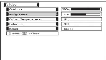
Use CURSOR PAD ◀ or ▶ to adjust brightness. Press MENU button to return to RGB MODE MENU and EXIT to quit.
Use the CURSOR PAD ◀ or ▶ to change the COLOR TEMPERATURE. Set to HIGH for a cooler picture with more blue (1,200K), set to MEDIUM for more natural color (9,300K), or set to STANDARD for accurate color (6,500K), or Black/White (5,400K).
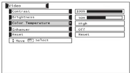
ENHANCER
Enhances the picture detail.
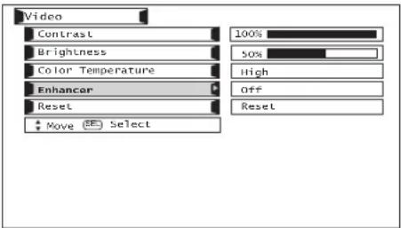
Use CURSOR PAD ◀ or ▶ to set ENHANCER Off, Low, Medium or High. Press SELECT button to ACCEPT and EXIT to quit.
RESET
Set CONTRAST, BRIGHTNESS, COLOR TEMPERATURE, and ENHANCER to factory preset condition.
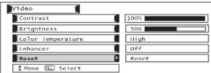
Use CURSOR PAD◀ or ▶ to highlight Reset. Press the SELECT button to RESET to factory preset settings.
ASPECT
Use this function to select the picture format aspect ratio while using RGB input.
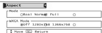
Use CURSOR PAD to highlight chosen selections. Press SELECT button to set and EXIT button to quit.
Recommendation
| Input Signal Mode | WXGA Mode |
| XGA Normal Off | |
| WXGA (1280x768) Full 1280x768 | |
| WXGA (1366x768) Full 1366x768 | |
RGB ASPECT DISPLAY MODE.
| RGB (Analog) INPUT SIGNAL | ||||||
| ASPECT MODE AVAILABILITY | Others | SVGA/XGA | VGA | 480p | 720p | 1080i |
| X | REAL | REAL | REAL(1) | X | X | |
| NORMAL | NORMAL | NORMAL | NORMAL(1) | X | X | |
| FULL | FULL | FULL | FULL(1) | FULL(2,3) | FULL(2,3) | |
For numbers in (), please see corresponding note below.
NOTES: 1. Lack of raster can be seen in RGB when a 480p signal is input.
-
AUTO ADJUST function (see page 85) is not available in 720p, 1080i, and 480p input signal.
-
FULL aspect mode, only 95% of information can be displayed (5% is treated as overscan).
AUTO ADJUST
HORIZONTAL POSITION, VERTICAL POSITION, HORIZONTAL CLOCK and CLOCK PHASE for current RGB format are adjusted automatically.
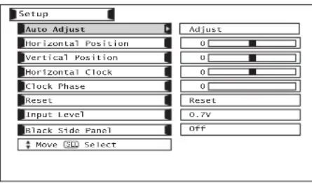
Use CURSOR PAD ◀, ▶ cursors to highlight adjust. Press SELECT to select AUTO ADJUST.
NOTES:• Press SELECT to AUTO ADJUST the RGB mode.
- The other functions do not operate while AUTO ADJUST is in progress.
- Allow the LCD TV to warm up for 20 minutes before performing AUTO ADJUST.
- Select a bright image for display while AUTO ADJUST takes place.
- If AUTO ADJUST terminates unsuccessfully, try AUTO ADJUST again. If AUTO ADJUST fails several times in succession, try using manual adjustment to adjust Vertical Frequency, Aspect Ratio, Timing Frequency and Picture.
- Always reset AUTO ADJUST when setting new display setting or when changing to a new external component.
H POSITION
This feature allows you to adjust the horizontal position of the display.
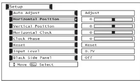
Use CURSOR PAD◀, ▶ to adjust the horizontal position. Press the MENU button to return to previous menu item. Press EXIT to quit.
V POSITION
This feature allows you to adjust the vertical position in RGB mode.

Use CURSOR PAD ◀, ▶ to adjust the vertical position.
Press MENU button to return to previous menu item. Press EXIT to quit.
HORIZONTAL CLOCK
Adjusts the pixel clock frequency to reduce the vertical stripe.
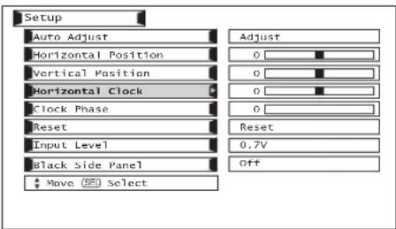
Use CURSOR PAD ◀, ▶ to adjust the horizontal clock. Press the MENU button to return to previous menu. Press EXIT to quit.
NOTE: Due to varying signal content, you may see vertical or horizontal lines bend occasionally in RGB mode. However, this phenomenon is not a defect. It's caused by a lack of picture content due to under-scanning in RGB mode.
CLOCK PHASE
Adjusts the phase to correct blurred or unstable images.
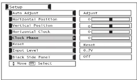
Use CURSOR PAD ◀, ▶ to adjust the clock phase. Press the MENU button to return to previous menu item. Press EXIT to quit.
RESET
Set HORIZONTAL POSITION, VERTICAL POSITION, HORIZONTAL CLOCK and CLOCK PHASE to factory preset, for current RGB format.
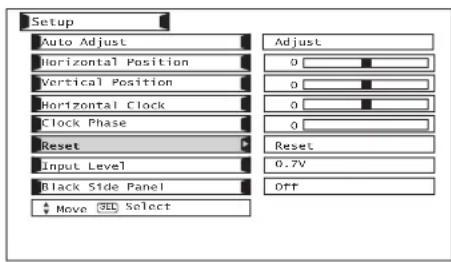
Use CURSOR PAD ◀, ▶ to highlight Reset. Press the SELECT button to RESET to factory preset settings.
INPUT LEVEL
Select the Input Level voltage between 0.7V and 1.0V.
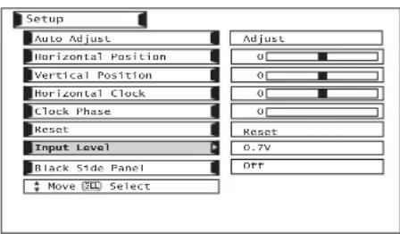
Use CURSOR PAD ◀, ▶ to select between 0.7V and 1.0V depending on the amount of brightness in the picture.
BLACK SIDE PANEL
The BLACK SIDE PANEL function turns the gray side bars ON/OFF when watching Aspect in Real and Normal signals in Standard Mode.
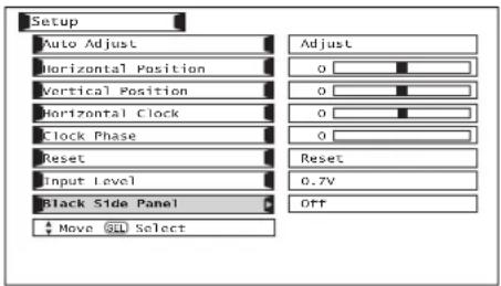
Press the SELECT button to select BLACK SIDE PANEL ON/OFF.
POWER SWIVEL
This feature controls the motorized stand. It allows the customer to turn the LCD display left or right using the remote control.
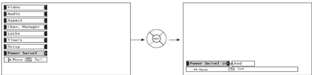
flowchart
graph LR
    A["Video"] --> C["Lock"]
    B["Audio"] --> C
    D["Aspect"] --> C
    E["Chan. Manager"] --> C
    F["Locks"] --> C
    G["Timers"] --> C
    H["Setup"] --> C
    I["Power Swivel"] --> C
    J["Move OK Sel."] --> C
    C --> K["Power Swivel Unlocked"]
    K --> L["Move OK Set"]
Exit OSD menu system before controlling the motorized stand.
Use CURSOR PAD ▶ to rotate the TV to the right.
Use CURSOR PAD ◀ to rotate the TV to the left.
Release the CURSOR PAD to stop rotation.
NOTES:
- The Power Swivel has a maximum turning radius of 30^ (left and right).
- Do not place any objects on the path of the monitor when using the power swivel feature.
- Before using the power swivel feature, please make sure that the path of the monitor is clear of any fingers, hands or any other body parts to avoid causing injury.
- When the Picture-in-Picture (PIP) or Freeze mode is ON, the Power Swivel is disabled.
DO
Dust the screen and frame with a cleaning cloth from the accessories pack.
Clean the screen and frame with a soft cloth moistened in warm water and dry with a soft cloth. A mild soap may be used if the screen is extremely dirty.
Place your LCD Television away from extreme heat, humidity, and extremely dusty places.
Remove the plug (AVC Center/Display Monitor) from the wall outlet if your LCD Television will not be used for a long period of time, for instance, when you go on vacation.
DO NOT
Do not clean your screen with strong cleaners, polishes or a chemically treated cloth.
Do not place rubber or vinyl products or cellophane tape on your LCD Television.
Avoid repeatedly touching the screen.
Do not subject the remote control to shocks such as dropping it on the floor, etc. This may cause physical damage to the precision parts.
Avoid placing the remote control in a high humidity place or getting it wet. Do not leave it on or near a heater. Excessive heat or moisture may cause the remote control unit to fail.
When the batteries run down, remote control operation will become erratic or become unresponsive. Replace the old batteries with two new "AA" size batteries. Do not use an old battery with a new battery.
Exposing the screen to direct sunlight for a long period of time or heat may cause damage to the LCD screen.
 | • IGNITION NOISE:Black spots or horizontal streaks may appear, picture may flutter or drift.Usually caused by interference from automobile ignition systems, neon lamps, electrical drills, and other electrical appliances. |
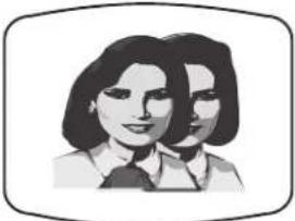 | • GHOSTS:Ghosts are caused by the television signal following two paths. One is the direct path and the other is reflected from tall buildings, hills or some other objects. Changing the direction or position of the antenna may improve reception. Ghosting may also be caused by defects in the antenna system such as unshielded leads or connecting several sets to the same antenna without using multiple antenna couplers. |
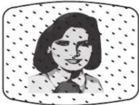 | • SNOW:If your receiver is located in the fringe area of a television station where the signal is weak, your picture may be marred by the appearance of small dots. When the signal is extremely weak, it may be necessary to install a special antenna to improve the picture. |
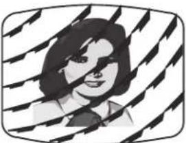 | • RADIO FREQUENCY INTERFERENCE:The interference produces moving ripples or diagonal streaks, and in some cases, causes loss of contrast in the picture. |
NOTE: The TV set can generate sound distortion in external devices such as a radio. Please separate radio equipment from the TV set to a considerable distance.
| SYMPTOMS | CHECK THESE ITEMS ANDTRY THESE ADJUSTMENTS | ||||||||||||
| Be sure external connection is correct | |||||||||||||
| Be sure power cord is plugged in | |||||||||||||
| Try another channel (station trouble) | |||||||||||||
| Check antenna connections (back of TV) | |||||||||||||
| Check antenna for broken lead-in wire | |||||||||||||
| Check outside antenna | |||||||||||||
| Adjust Contrast control | |||||||||||||
| Adjust Color control | |||||||||||||
| Adjust Tint control | |||||||||||||
| Adjust Volume control | |||||||||||||
| No Picture, no sound | ● | ● | ● | ● | ● | ● | ● | ||||||
| Sound OK, picture poor | ● | ● | ● | ● | ● | ● | ● | ● | |||||
| Picture OK, sound poor | ● | ● | ● | ● | ● | ● | ● | ||||||
| Picture blurred | ● | ● | ● | ● | ● | ● | |||||||
| Lines or streaks in picture | ● | ● | ● | ● | ● | ||||||||
| Poor reception on some channels | ● | ● | ● | ● | ● | ||||||||
| Picture rolls vertically | ● | ● | |||||||||||
| No color | ● | ● | ● | ● | ● | ● | |||||||
| Poor color | ● | ● | ● | ● | ● | ● | ● | ||||||
| Dark Picture | ● | ● | |||||||||||
HITACHI Liquid Crystal Display incorporates advanced power surge protection technology designed to protect against component or circuit damage due to external or internal voltage power surges.
IF YOUR TELEVISION SHOULD APPEAR TO HAVE A LOSS OF POWER, PLEASE FOLLOW THIS PROCEDURE:
- Press the power switch (ON/OFF switch) once.
- If there is still no power, wait 30 seconds and press the power switch again.
- If there is still no power, unplug the power cord from the wall. Wait 30 seconds and plug the power cord back in. Press the power switch again.
This protective technology should provide for years of lasting entertainment from your HITACHI Liquid Crystal Display.
This LCD Television complies with VESA DDC2B specifications, Plug & Play is a system with computer, peripherals (including monitors) and operating system. It works when the monitor is connected to a DDC ready computer that is running an operating system software that is capable for the plug & play.
When a Plug and Play PC is powered on, it sends a command to the Monitor requesting identification. The Monitor sends back a string of data including its characteristics.
natural_image
Cartoon illustration of a smiling computer monitor with eyes and nose (no text or symbols)TRADEMARK ACKNOWLEDGMENT
DDC ^™ is a trademark of Video Electronics Standard Association. IBM PC/AT and VGA are registered trademarks of International Business Machines Corporation of the U.S.A. Apple and Macintosh are registered trademarks of Apple Computer, Inc. VESA is a trademark of a nonprofit organization, Video Electronics Standard Association.
This Class B digital apparatus meets all requirements of the Canadian Interference-Causing Equipment Regulations. This Class B digital apparatus complies with Canadian ICES-003.
Cet appareil numérique de la classe B est conforme à la norme NMB-003 du Canada.
Cable Compatible Television Apparatus- Télèvision câblocompatible, Canada.
Notes on Closed Caption:
This LCD Television receiver will display television closed captioning, (CC or □), in accordance with paragraph 15.119 of the FCC rules.
AGENCY REGULATORY INFORMATION
Federal Communications Commission Notice
This equipment has been tested and found to comply with the limits for a Class B digital device, pursuant to Part 15 of the FCC Rules. These limits are designed to provide reasonable protection against harmful interference in a residential installation. This equipment generates, uses and can radiate radio frequency energy and if not installed and used in accordance with the instructions, may cause harmful interference to radio communications. However, there is no guarantee that interference will not occur in a particular installation. If this equipment does cause harmful interference to radio or television reception, which can be determined by turning the equipment off and on, the user is encouraged to try to correct the interference by one or more of the following measures:
- Reorient or relocate the receiving antenna.
- Increase the separation between the equipment and the receiver.
- Connect the equipment into an outlet on a circuit different from that to which the receiver is connected.
- Consult the dealer or an experienced radio/television technician for help.
Modifications
The FCC requires the user to be notified that any changes or modifications made to this device that are not expressly approved by Hitachi Home Electronics (America), Inc. may void the user's warranty.
Cables
Connections to this device must be made with shielded cables with metallic RFI/EMI connector hoods to maintain compliance with FCC Rules and Regulations.
Any cables that are supplied with the system must be replaced with identical cables in order to assure compliance with FCC rules. Order Hitachi spares as replacement cables.
Declaration of Conformity
This device complies with Part 15 of the FCC Rules. Operation is subject to the following two conditions: (1) this device may not cause harmful interference and (2) this device must accept any interference received, including interference that may cause undesired operation.
For questions regarding this declaration, contact:
Hitachi America, LTD.
Home Electronics Division
900 Hitachi Way
Chula Vista, CA 91914-3556
Tel. 1-800-448-2244 (1-800-HITACHI)
ATTN: CUSTOMER RELATIONS
Features:
- New Easy-to-Use On-Screen Menu Control (3 Language)
- New AV Network System Control Control up to 4 components with one remote 2 IR Mouse cables included Control Codes Stored in AV Control Center
- Two Tuner Split Screen except RGB modes.
- Illuminated and Preprogrammed Remote Control
• Power Management: ON/OFF via signal detection - Menu Control Keys accessible from AV Control Center
• Picture Enhancement - Input Signal Identification
- CableCARD compatible - Contact your local cable operator for more information
- HDMI (High Deifinition Multimedia Interface)(High Bandwidth Digital Content Protection V1.1 Compatible)
• Photo Input (for your digital camera)
Video:
• 1366 x 768 Display Resolution (32")
• High-Contrast Pure-Color Glass Shield
- Wide Viewing Angle: More than 170°
- 4 Color Temperature Presets: Black/White-5400K, Standard-6500K, Medium-9300K, High-1200K.
- Multiple Screen Fill Modes (4:3 Standard/Expanded/Zoom1/Zoom2/16:9 Standard/Zoom) ^1
• 4MB 10-bit 3D Y/C Comb Filter
• Picture Modes (Day and Night)
- Computer Display: VGA, (SVGA, XGA, SXGA-scaled) (32")
Inputs:
• Power Input .....AC 120V, 60Hz
- Power Consumption
- Refer to rear panel at the back of the LCD Monitor and AVC Center
- Antenna input impedance ....75 Ohm
- Channel coverage .....191ch.
VHF-Band .....2 \~ 13
UHF-Band .....14 \~ 69
CATV Mid Band .....A-5 \~ A-1
.....A-I
Super Band .....J-W
Hyper Band .....W+1 - W+28
Ultra Band .....W+29 - W+94
• Video .....1.0Vp-p, 75 Ohm
- S-Video
Luminance (Y) .....1.0Vp-p, 75 Ohm
Chrominance (C) .....0.286Vp-p, 75 Ohm
- Component Video
Luminance (Y) ....1.0Vp-p, 75 Ohm
Chrominance (P B /P R ) ....0.7Vp-p, 75 Ohm
• Audio input Impedance .....47k Ohm
• Average input level .....470mVrms
- RGB 0.7Vp-p, 75 Ohm
• HDMI .....(19 PIN)
Outputs:
• Video .....1.0Vp-p. 75 Ohm
• Audio .....470mVrms, 1k Ohm
• Optical Out (Digital Audio) ....1 Optical Connector
Audio:
- MTS Stereo/SAP
• Dynamic Bass and Matrix Surround - 10W+10W
- Soft Mute (50% and 100%)
Supplied Accessories:
- Remote Control
- Batteries
• 9' Monitor Connection Cable - 6' AC Cable (2)
- Subwoofer Cable
- IR Mouse Cable (2)
INPUTS/OUTPUTS
- Inputs: ......RGB, VIDEO 1-5
- Wideband Component Y, Pb,Pr ....2
- RGB: Analog Input ....1
- Composite Video....5
• S-Video ....3 - Antenna (RF) Inputs....2
- Audio Output....1
• Monitor Output ....1
• Headphone Output....1 - Subwoofer Output ....1
• HDMI 2 - Photo Input....1
- IEEE 1394....2
SPECIFICATIONS
- Multi-Scanning: 24-109kHz (h), 50-85Hz (v)
- Pixel Pitch ....0.51(horiz.) x 0.51(vert.) mm (32")
- FCC class: ......B for Consumer Use
• Power Requirements: 108-132V, 60Hz
DIMENSIONS
32"
- Width 30 3/4"
• Height 17 3/4"
• Depth 2 1/16"
• Weight 86 lbs.
Audio Video Control Center
- Width 16 15/16"
• Height....3 3/8" - Depth....9 1/2"
- Weight....9.5 lbs.
^1 Screen mode availability varies by input format HDTV Monitors display HDTV when combined with an HDTV Tuner and Source. All specifications, weights, and dimensions are subject to change without prior notice. Please access www.hitachi.com/tv for detailed specifications and dimensions for custom installations.
UltraVision Digital is a registered trademark of Hitachi Home Electronics (America), Inc.

HDMI, the HDMI logo and High-Definition Multimedia Interface are trademarks or registered trademarks of HDMI Licensing LLC.
HITACHI

To locate an authorized HITACHI service facility in the continental U.S.A. and Canada,
DIAL TOLL FREE
7 days a week, 24 hours a day
800 HITACHI
(1-800-448-2244)
Hitachi America, LTD. Home Electronics Division
Hitachi has made every effort to assure you hours of trouble free operation from your unit. However, should you require service, a network of Hitachi Authorized Service Facilities has been established in all 50 states and Puerto Rico. Each facility will provide you with convenient and expedient assistance. Our service hotline operator will direct you to the Hitachi Authorized Service Facility nearest you. Just present proof of purchase and/or delivery receipts to the Hitachi Authorized Service Facility, and service will be rendered in accordance with the terms of the limited warranty as stated on your warranty card or operating guide.
Should you have any questions regarding warranty, service, operation, or technical assistance, please contact:
Hitachi America, LTD.
Home Electronics Division
900 Hitachi Way
Chula Vista, CA 91914-3556
Hitachi Canada, LTD. Digital Media Division
Should you have any questions regarding warranty, service, operation, or technical assistance, please contact:
In Canada:
1-800-HITACHI
(1-800-448-2244)
Monday - Friday EST 9:00am - 7:00pm
Saturday EST 9:00am - 5:00pm
Look for your French Manual on the outside of the box.
If the manual is missing, call
1-800-HITACHI
(1-800-448-2244)
for a copy.
Lundi - Vendredi L'EST 9:00am - 7:00pm
Samedi L'EST 9:00am - 5:00pm
2495 Meadowpine Blvd.
Mississauga, ON L5N 6C3
A
Accessories, 4
Antennas (Connecting), 8
Antenna Setup 60
Aspect Ratio, 29, 59
Audio (Sound Enhancement)
Audio Settings 57
Audio Source 57
Auto Adjust (RGB Input) .....85
Auto Noise Cancel 57
A/V Network .....22-24, 31-32
B
Balance 57
Bass 57
Caution and Safety Tips 2-3
Channel Manager....60-61
Auto Channel Scan 60
Clock
Phase 86
Time 67
Closed Captions
Captions 75
Color Management ....55
Color Decoding ....56
Color Temperature 54
Color 54
Contrast 54
Contrast Mode 54
E
Event Timer 69
External Video Source .....14-22
F
Favorite Channel 38
Freeze 28
H
HDMI 18
|
Input Setup 73-74
IEEE 1394 .20,36
L
Language
Menu Language ....71
Locks
Change Access Code 62
Channel Lock 62
Front Panel Lock 62
Input Lock 62
Movie Ratings 63
TV Ratings 64
TV Ratings (Canadian - English) . . . . . . . . . . . . . . . . . . . . . . . . . . . . . . . . . . . . . . . . . . 65
TV Ratings (Canadian - French) .....66
M
Matrix Surround ....57
Menu Preference
Language 71
Background 72
Monitor Out 76
N
Noise Reduction 56
P
Perfect Volume 57
Photo Input 33-35
Picture Mode 53
Picture-in-Picture (PIP) .....39-41
Position (RGB Input)
Horizontal 85
Vertical 85
R
Remote Control
Functions 27-49
Programming Codes 48-49
Installing Batteries 4
R/G/B .....25, 78-87
S
Screen Saver....72
Sharpness ....54
Speakers .....57
Connecting External Speakers .....21
Internal Speakers 57
Split Mode 40
T
Timers....67-70
Time 67
Tint 54
Treble 57
V
Video Settings ....53-56
END USER LICENSE AGREEMENT FOR HITACHI DTV SOFTWARE
IMPORTANT – READ CAREFULLY: This License Agreement is a legal agreement between you and Hitachi America, Ltd., Home Electronics Division ("HAL-HED"). By using this Hitachi digital television (the "DTV") and its software (the "Software"), you agree to be bound by the terms of this License Agreement. IF YOU DO NOT AGREE TO BE BOUND BY THIS LICENSE AGREEMENT, DO NOT USE THIS DTV AND ITS SOFTWARE.
The Software is protected by copyright laws and international copyright treaties, as well as other intellectual property laws and treaties. The Software is licensed, not sold.
- LICENSE GRANT. Subject to all of the terms, conditions and restrictions of this License Agreement, HAL-HED grants to you a limited, revocable, non-exclusive right to use one copy of the Software only on one Hitachi labeled DTV owned by you.
- RIGHTS AND LIMITATIONS. Software Not for Resale. You may not resell or otherwise transfer for value the Software, except that you may transfer the Software as part of a resale of the entire DTV product only. Prohibition on Reverse Engineering, Decompilation, Disassembly and/or Modification. You may not reverse engineer, decompile, disassemble or modify the Software.
Separation of Components. The Software is licensed as single product. Its component parts may not be separated for use on more than one DTV.
No Transfers. You may not transfer, assign, rent, lease, lend or in any way sublicense the Software.
Trademarks. This License Agreement does not grant you any rights to any trademarks.
Third Party Software. You shall not use the Software in combination with any third party software.
- VIOLATIONS; INDEMNITY. You understand that any use, copying or transfer of the Software, except as permitted pursuant to this License Agreement, constitutes a violation of legal rights and may subject you to damages and an award to HAL-HED of attorneys' fees in connection with any violation of this License. You further understand that you may be held legally responsible for any copyright infringement or other violation of intellectual property rights that is caused or encouraged by your failure to abide by the terms of this License Agreement. You agree to defend, indemnify and hold HAL-HED and its parent and affiliate companies harmless from and against any and all liability resulting from any breach by you of this License Agreement and/or any use by you of the Software in combination with third party software.
- COPYRIGHT. All title and intellectual property rights in and to the Software (including but not limited to any images, photographs, animation, video, audio, music, text, and "applets" incorporated into the Software), and any accompanying printed materials are owned by HAL-HED. All title and intellectual property rights in and to the content which may be accessed through use of the Software is the property of the respective content owner and may be protected by applicable copyright or other intellectual property laws and treaties. This License Agreement grants you no rights to use such content. All rights not expressly granted are reserved by HAL-HED. This provision applies to U.S. Government end-users, who are granted only those rights expressly set forth herein.
- EXPORT RESTRICTIONS. HAL-HED is licensing the Software for use within the United States only. You agree that you will not export or re-export the Software. You specifically agree not to export or re-export the Software: (i) to any country to which the U.S. has embargoed or restricted the export of goods or services, which currently include, but are not necessarily limited to Cuba, Iran, Iraq, Libya, North Korea, Sudan, and Syria, or to any national of any such country, wherever located, who intends to transmit or transport the Software back to such country; (ii) to any person or entity who you know or have reason to know will utilize the Software in the design, development, or production of nuclear, chemical, or biological weapons; or (iii) to any person or entity who has been prohibited from participating in U.S. export transactions by any federal agency of the U.S. government. You warrant and represent that neither the Bureau of Export Administration (BXA) nor any other U.S Federal Agency has suspended, revoked, or denied your export privileges.
-
NO WARRANTIES. THE SOFTWARE IS PROVIDED "AS-IS, WHERE-IS." HAL-HED MAKES NO WARRANTIES OF ANY KIND WHATSOEVER REGARDING THE SOFTWARE AND, TO THE MAXIMUM EXTENT PERMITTED BY LAW, HEREBY EXPRESSLY DISCLAIMS ALL WARRANTIES OF ANY KIND WHATSOEVER, EXPRESS OR IMPLIED, WITH RESPECT TO THE SOFTWARE. ALL IMPLIED WARRANTIES, INCLUDING WITHOUT LIMITATION, THE IMPLIED WARRANTIES OF NON-INFRINGEMENT, MERCHANTABILITY AND FITNESS FOR A PARTICULAR PURPOSE ARE HEREBY EXPRESSLY DISCLAIMED TO THE MAXIMUM EXTENT PERMITTED BY LAW.
-
LIMITATION OF LIABILITY. IN NO EVENT SHALL HAL-HED OR ANY OF ITS PARENT OR AFFILIATE COMPANIES BE LIABLE TO YOU OR ANY THIRD PARTY FOR ANY DIRECT, INDIRECT, INCIDENTAL, SPECIAL, EXEMPLARY, OR CONSEQUENTIAL DAMAGES (INCLUDING, BUT NOT LIMITED TO, PROCUREMENT OF SUBSTITUTE GOODS OR SERVICES; LOSS OF USE, DATA, OR PROFITS; LOSS OF GOODWILL, EXPENDITURES MADE OR COMMITTED FOR IN RELIANCE ON THE CONTINUATION OF THIS LICENSE AGREEMENT OR BUSINESS INTERRUPTION) HOWEVER CAUSED AND ON ANY THEORY OF LIABILITY, WHETHER IN CONTRACT, STRICT LIABILITY, OR TORT (INCLUDING NEGLIGENCE OR OTHERWISE) ARISING IN ANY WAY OUT OF THE USE OF THE SOFTWARE, EVEN IF ADVISED OF THE POSSIBILITY OF SUCH DAMAGE.
- NO FAILURE OF ESSENTIAL PURPOSE. YOU AGREE THAT NO FAILURE TO REPAIR A DEFECT, ERROR OR BUG IN THE SOFTWARE SHALL CONSTITUTE A FAILURE OF THE ESSENTIAL PURPOSE OF THIS LICENSE AGREEMENT.
- CRYPTOGRAPHIC SOFTWARE. THIS PRODUCT CONTAINS SOFTWARE DEVELOPED BY THE OpenSSL PROJECT INCLUDING CRYPTOGRAPHIC SOFTWARE WRITTEN BY ERIC YOUNG (THE "CRYPTOGRAPHIC SOFTWARE"). THE CRYPTOGRAPHIC SOFTWARE IS PROVIDED BY THE OpenSSL PROJECT "AS IS" AND ANY EXPRESSED OR IMPLIED WARRANTIES, INCLUDING BUT NOT LIMITED TO, THE IMPLIED WARRANTIES OF MERCHANTABILITY AND FITNESS FOR A PARTICULAR PURPOSE ARE HEREBY EXPRESSLY DISCLAIMED TO THE MAXIMUM EXTENT PERMITTED BY LAW. IN NO EVENT SHALL THE OpenSSL PROJECT, ITS CONTRIBUTORS, HAL-HED OR ANY OF ITS PARENT OR AFFILIATE COMPANIES BE LIABLE FOR ANY DIRECT, INDIRECT, INCIDENTAL, SPECIAL, EXEMPLARY, OR CONSEQUENTIAL DAMAGES (INCLUDING, BUT NOT LIMITED TO, PROCUREMENT OF SUBSTITUTE GOODS OR SERVICES; LOSS OF USE, DATA, OR PROFITS; OR BUSINESS INTERRUPTION) HOWEVER CAUSED AND ON ANY THEORY OF LIABILITY, WHETHER IN CONTRACT, STRICT LIABILITY, OR TORT (INCLUDING NEGLIGENCE OR OTHERWISE) ARISING IN ANY WAY OUT OF THE USE OF THE SOFTWARE OR THE CRYPTOGRAPHIC SOFTWARE, EVEN IF ADVISED OF THE POSSIBILITY OF SUCH DAMAGE.
- TERMINATION. This License Agreement may be terminated at any time by HAL-HED effective immediately upon notice to you.
- GOVERNING LAW; SEVERABILITY. This Agreement shall be governed and construed in accordance with the laws of the State of California, without regard to its conflict of laws rules, and any disputes hereunder shall be subject to the exclusive jurisdiction and venue of the U.S. Federal Courts in the Southern District of California. If any part of this License Agreement is unenforceable, the remainder shall be valid and binding to the maximum extent permitted by applicable law.
HITACHI
QR62241
- AVC (Audio Video Control Center) & LCD Display Monitor
- Operating Guide for 32HDL51
- SAFETY POINTS YOU SHOULD KNOW ABOUT YOUR HITACHI LCD TELEVISION
- POWER SOURCE
- Read before operating equipment
- Do not place any objects on the top of the television which may fall or cause a child to climb to retrieve the objects.
- PUBLIC VIEWING OF COPYRIGHTED MATERIAL
- REMOTE CONTROL BATTERY INSTALLATION AND REPLACEMENT
- Securing to a table-top
- Securing to a wall
- Caution when moving the main unit
- ANTENNA
- LOCATION
- VIEWING
- 300-Ohm Twin Lead Connector
- Phono Connector
- Stereo Cable (3.5 mm plug to 3.5 mm plug)
- IR Mouse Cable (Provided)
- Subwoofer Cable (Provided)
- Optical Cable
- HDMI Cable
- IEEE1394 Cable
- “F” Type 75-Ohm Coaxial Antenna Connector
- S-Video (Super Video) Connector
- D-SUB MINI 15-Pin Cable
- Monitor Connection Cable (Provided)
- D-SUB MINI 9-Pin Cable
- USB Cable
- VHF (75-Ohm) antenna/CATV (Cable TV)
- VHF (300-Ohm) antenna/UHF antenna
- When both VHF and UHF antennas are connected
- ①MENU/SELECT button
- ②PHOTO INPUT
- ③INPUT/EXIT button
- ④CHANNEL selector
- ⑤VOLUME level
- ⑥POWER button
- Display Monitor "MAIN POWER" button
- AVC POWER button
- ⑦POWER light indicator
- ⑧REMOTE CONTROL sensor
- ⑨FRONT INPUT JACKS (for VIDEO: 5)
- ⑩PHONES JACK
- ⑪ LEARNING AV NET Sensor
- ①Antenna Input
- ②Audio/Video Inputs 1, 2, 3 and 4
- ③MONITOR OUT
- ④Optical Out (Digital Audio)
- ⑤S-VIDEO Inputs 3 and 4
- ⑥Component: Y-P _B P _R Inputs
- ⑦RGB - Analog Input
- ⑧RGB - Audio Input
- ⑨HDMI - Digital Input (INPUT 1 and INPUT 2)
- About HDMI
- HDMI
- ⑩To Monitor
- ⑪IR Blaster
- ⑫RS232C Input
- ⑬IEEE1394
- ⑭Subwoofer Out
- ⑮To AVC
- ⑯SUB-POWER button
- ⑰ Upgrade Card
- ⑱To Power Swivel Connector
- ⑲CableCARD Slot
- CONNECTING EXTERNAL VIDEO SOURCES
- Before Operating External Video Source
- CONNECTING A MONAURAL AUDIO SOURCE TO INPUT1\~INPUT5
- CONNECTING A STEREO VCR OR STEREO LASERDISC PLAYER
- NOTES:
- CONNECTING S-VIDEO VCR OR LASERDISC PLAYER
- CONNECTING A COMPONENT SOURCE WITH HDMI or DVI CAPABILITY TO INPUT 1 or INPUT 2
- CONNECTING A STEREO LASERDISC/DVD PLAYER OR HDTV SET TOP BOX TO INPUT 1 OR 2 COMPONENT: Y-R _B P _R .
- CONNECTING A COMPONENT SOURCE WITH DIGITAL INTERFACE CAPABILITY TO IEEE1394 TERMINALS
- CONNECTING EXTERNAL AUDIO AMPLIFIER
- CONNECTING EXTERNAL AUDIO/VIDEO COMPONENTS TO IR BLASTER FOR AV NETWORK
- ⑥ASPECT button
- ⑦DAY/NIGHT button
- ⑧PICTURE-IN-PICTURE button
- ⑨MENU button
- ⑩GUIDE button
- ⑪ EXIT button
- ⑫CURSOR PAD/SELECT button
- ⑬AV NET button
- ⑭INPUTS button
- Photo Input
- SLIDESHOW
- ROTATE
- ⑮INFO button
- ⑯VOLUME (VOL) WHEEL, MUTE button
- ⑰CHANNEL (CH) WHEEL/CHANNEL SELECTOR buttons
- ⑱(-) DASH button
- ⑲LAST CHANNEL (LC) button
- ① PIP button
- POP MODE PICTURE-IN-PICTURE
- PIP MODE PICTURE-IN-PICTURE
- SPLIT MODE PICTURE-IN-PICTURE
- SURF MODE PICTURE-IN-PICTURE
- ② PAUSE button
- MAIN FREEZE
- SPLIT FREEZE
- STROBE FREEZE
- Operating the precoded function for your cable box.
- ①PRE-CODED SET-TOP-BOX/SATELLITE RECEIVER buttons
- ② EXCLUSIVE TV buttons
- Operating the precoded function for your DVD player.
- Operating the precoded function for your Audio component.
- ①PRECODED AUDIO Buttons
- INPUT ACCESS
- SETUP EXAMPLE (Hitachi DVD with precode 0573 connected to INPUT 1 of the TV)
- OSD (On-Screen Display)
- Video
- Picture Mode
- Contrast
- Brightness
- Color
- Tint
- Sharpness
- Color Temperature
- Black Enhancement
- Contrast Mode
- Back Light
- Reset Video Settings
- Color Management
- Color Decoding
- Auto Color
- Noise Reduction
- Auto Movie Mode
- AUDIO
- Language
- Digital Output
- DRC
- Aspect
- Auto Aspect
- Vertical Position
- Chan. Manager
- Set The Antenna
- Auto Channel Scan
- Signal Meter
- Channel List
- Locks
- Movie Ratings
- TV Ratings
- TV Parental Guide Ratings Chart
- Canadian Ratings (Eng)
- Canadian Ratings (Frn)
- Canadian Ratings French Chart
- Timers
- Set The Clock
- Set Sleep Timer
- Set Day/Night Timer
- Set Event Timer
- NOTE:
- Set Timer Recording
- Setup
- Menu Preference
- MENU
- Menu Background
- Option 1
- Option 2
- Option 3
- Screen Wipe
- Set The Inputs
- Video Power Save
- Video 2 Auto Link
- Set Black Side Panel
- Set Closed Caption
- Set Monitor Out
- CableCARD Info
- Set AV Control
- Upgrades
- Set Stand-By Mode
- Power Swivel
- VIDEO ADJUSTMENTS
- ENHANCER
- RESET
- AUTO ADJUST
- H POSITION
- V POSITION
- HORIZONTAL CLOCK
- CLOCK PHASE
- INPUT LEVEL
- BLACK SIDE PANEL
- DO
- DO NOT
- TRADEMARK ACKNOWLEDGMENT
- Notes on Closed Caption:
- AGENCY REGULATORY INFORMATION
- Federal Communications Commission Notice
- Modifications
- Cables
- Declaration of Conformity
- Features:
- Video:
- Inputs:
- Outputs:
- Audio:
- Supplied Accessories:
- INPUTS/OUTPUTS
- SPECIFICATIONS
- DIMENSIONS
- Audio Video Control Center
- HITACHI
- DIAL TOLL FREE
- HITACHI
- Hitachi America, LTD. Home Electronics Division
- Hitachi Canada, LTD. Digital Media Division
- A
- B
- E
- F
- H
- |
- L
- M
- N
- P
- R
- S
- T
- V
- END USER LICENSE AGREEMENT FOR HITACHI DTV SOFTWARE
Brand : HITACHI
Model : 32HDL51
Category : Television