
AVT 100P - Démodulateur TV Extron - Free user manual and instructions
Find the device manual for free AVT 100P Extron in PDF.


| Product Type | Analog TV and Cable Demodulator |
| Model | AVT 100P (PAL version) |
| Dimensions (Height x Width x Depth) | 1.7" x 4.3" x 6.7" (4.3 cm x 10.9 cm x 17.0 cm) |
| Weight | 0.8 lbs (0.4 kg) |
| Power Supply | External 12 VDC, 0.5 A; autoswitchable 100-240 VAC, 50/60 Hz |
| Enclosure | Metal, 1U high, quarter-rack wide |
| RF Input Connector | 1 female IEC 169-2, 75 ohms (PAL model) |
| Video Output Connector | 1 BNC female, composite video |
| Audio Output | 1 balanced/unbalanced stereo, 5-pole captive screw connector |
| Control Interface | RS-232 via 5-pole captive screw; optional wired IR |
| Channel Reception (PAL) | Antenna and cable channels 48-855 |
| Presets | 99 for antenna, 99 for cable (total 198) |
| Audio Muting | Yes, via front panel, IR remote, or SIS command |
| Video Muting | Yes, via front panel, IR remote, or SIS command |
| Front Panel Security Lockout | Yes (Executive mode) via SIS or software |
| IR Remote Control | Optional hand-held remote, up to 30 feet range |
| Auto-Scan Function | Scans all channels and saves active signals |
| PAL Standard Selection | B/G (default), D/K, I |
| Compliance | CE, FCC Class A, VCCI, AS/NZS, ICES |
| Operating Temperature | +32 to +122 °F (0 to +50 °C) |
| Warranty | 3 years parts and labor |
| Maintenance | No user-serviceable parts; refer servicing to qualified personnel |
| Included Accessories | Power supply, power cord, rubber feet, Tweeker, user manual, software on disk |
Frequently Asked Questions - AVT 100P Extron
User questions about AVT 100P Extron
0 question about this device. Answer the ones you know or ask your own.
Ask a new question about this device
Download the instructions for your Démodulateur TV in PDF format for free! Find your manual AVT 100P - Extron and take your electronic device back in hand. On this page are published all the documents necessary for the use of your device. AVT 100P by Extron.
USER MANUAL AVT 100P Extron
Analog TV and Cable Demodulator
68-905-01 Rev G
01 08

www.extron.com
Extron Electronics, USA
1230 South CHW St Jocelyn, Cl. 93075
Alzheim, CA 50430 501672056, 214491190
Fax 71449115:7
Extron Electronics, Europe
Beeilschemmberg 60
3521 At Amsterdam, The Netherlands
FAX +31 33 453 0360
Extron Electronics, Asia
135 Joo Seno Rd. #04-01
PA Industrial Eng., Singapore - Onside (810-5739865) - US 5192.4400
TAX -35.8203.4861
Extron Electronics, Japan
Ryde Building, 16 kbitanche
Chiyots-81, Tokyo 102-0652
+61 3 551 7855 (A) -01 3 551 7856
Precautions
Safety Instructions • English

This symbol is intended to alert the user of important operating and maintenance (servicing) instructions in the literature provided with the equipment.

This symbol is intended to alert the user of the presence of uninsulated dangerous voltage within the product's enclosure that may present a risk of electric shock.
Caution
Read instructions • Read and understand all safety and operating instruments before using the equipment.
Retain Instructions + the safety instructors should be kept for future
Follow Warnings • Follow all warnings and awareness posted on the seasonal or in the year introduction.
Avoid Attachments * Do not use tools or attachments that are not
We believe by the equal amount of cash, in 14 May and 15 July to be recorded.
Andes in your plan, 24.19.18 in the Nitzelschutzschutz
Power sources. This equipment should be operated only from the power source
the first of the 2013. The approximation is described to be used with the power system with a grounded (neutral) combinator. The third (grounding) put in a safety mixture, do not attempt to bypass or displace it.
Power disconnection * To remove power from the equipment safety, remove all power cards from the rear of the equipment, or the desktop power module (if detachable), or turn the power source receptacle (wall plug).
Power coal protection + Power cars should be sold so that they are not likely to be equipped on or passed by them placed upon or against them.
Servicing • Referral servicing to qualified service personnel. There are no use of servitable parts contracts, to prevent the risk of shock, do not attempt to serve the equipment yourself because opening or removing and often may expand you to determine willower or other resources.
Slots and openings of the equipment has slots or holes in the enclosure, these are provided to cover, outlining of accordance with its own tools. These openings must never be blocked by other objects.
1 Lithium memory. There is a danger of exploitation if Kennedy is increasingly replaced
Manufacturers. Filgons of used timber or zirconite to the manufacturer's
15年五月16日
Avertissement
Extron Electronics warrants this product against defects in materials and workmanship for a period of three years from the date of purchase. In the event of malfunction during the warranty period attributable directly to faulty workmanship and/or materials, Extron Electronics will, at its option, repair or replace said products or components, to whatever extent it shall deem necessary to restore said product to proper operating condition, provided that it is returned within the warranty period, with proof of purchase and description of malfunction to:
USA, Canada, South America, Europe, Africa, and the Middle East; and Central America:
Extron Electronics Beeldschermweg 6C 1001 East Ball Road 3821 AH Amersfoort Anaheim, CA 92805, USA The Netherlands
Asia: Japan:
Extron Electronics, Asia Extron Electronics, Japan 135 Joo Seng Road, #04-01 Kyodo Building PM Industrial Bldg. 16 Ichibancho Singapore 368363 Chiyoda-ku, Tokyo 102-0082
Japan
This Limited Warranty does not apply if the fault has been caused by misuse, improper handling care, electrical or mechanical abuse, abnormal operating conditions or non-Extron authorized modification to the product.
If it has been determined that the product is defective, please call Extron and ask for an Applications Engineer at (714) 491-1500 (USA), 31.33.453.4040 (Europe), 65.6383.4400 (Asia), or 81.3.3511.7655 (Japan) to receive an RA# (Return Authorization number). This will begin the repair process as quickly as possible.
Units must be returned insured, with shipping charges prepaid. If not insured, you assume the risk of loss or damage during shipment. Returned units must include the serial number and a description of the problem, as well as the name of the person to contact in case there are any questions.
Extron Electronics makes no further warranties either expressed or implied with respect to the product and its quality, performance, merchantability, or fitness for any particular use. In no event will Extron Electronics be liable for direct, indirect, or consequential damages resulting from any defect in this product even if Extron Electronics has been advised of such damage.
Please note that laws vary from state to state and country to country, and that some provisions of this warranty may not apply to you.
安全须知 · 中文

This equipment has been tested and found to comply with the limits for a Class A digital device, pursuant to part 15 of the FCC Rules. Operation is subject to the following two conditions: (1) this device may not cause harmful interference, and (2) this device must accept any interference received, including interference that may cause undesired operation. The Class A limits are designed to provide reasonable protection against harmful interference when the equipment is operated in a commercial environment. This equipment generates, uses, and can radiate radio frequency energy and, if not installed and used in accordance with the instruction manual, may cause harmful interference to radio communications. Operation of this equipment in a residential area is likely to cause harmful interference, in which case the user will be required to correct the interference at his own expense.
NOTE
This unit was tested with shielded cables on the peripheral devices. Shielded cables must be used with the unit to ensure compliance with FCC emissions limits.
Precautions, cont'd
Table of Contents
Chapter 1 • Introduction....1-1
About This Manual 1-2
About the AVT 100 Demodulator 1-2
Models 1-2
Features 1-2
Application diagram 1-4
Chapter 2 • Installation and Connection ..... 2-1
Mounting the AVT 100 2-2
Tabletop use 2-2
Rack mounting 2-2
UL requirements for rack mounting 2-2
Rack mounting procedure 2-3
Rear Panel Features 2-4
Wiring and Connecting the RS-232 Cable 2-6
Connecting the AVT 100 to the IR Link 2-7
Connecting the AVT 100 to a MediaLink™
Controller 2-9
Chapter 3 • Operation....3-1
Front Panel Features 3-2
Using the Control Buttons 3-2
Changing the channel 3-2
Initiating Auto-Scan 3-3
Adding and deleting channels.... 3-3
Special Functions 3-3
Locking front panel controls (executive mode) 3-3
Selecting tune or preset mode 3-4
Presets 3-4
Muting the audio and video outputs 3-5
Selecting the audio output mode 3-5
Selecting the PAL broadcasting standard 3-6
Selecting the cable TV frequency (NTSC only) 3-6
Using the IR Remote for AVT 100 3-6
Locking IR remote access 3-7
Installing batteries in the IR remote 3-7
Buttons on the AVT 100 IR Remote Control 3-8
Selecting a channel (tuning) using the IR remote 3-9
Saving a preset using the IR remote 3-10
Table of Contents, cont'd
Chapter 4 • Software Configuration and Control 4-1
Using Simple Instruction Set (SIS™) Commands .... 4-2
Host-to-AVT communications 4-2
AVT 100-initiated messages 4-2
Error responses 4-3
Using the command/response tables.... 4-3
Symbol definitions 4-4
Command/response table for SIS commands 4-5
Command/response table for special function SIS
commands 4-8
Advanced Instruction Set commands 4-13
Windows®-Based Control/Configuration
Software 4-14
Compatibility 4-14
Installing the software 4-14
Starting the software program.... 4-16
Using the Windows-based control/configuration
software Help 4-17
Appendix A • Specifications, Parts, and
Accessories ...... A-1
Specifications A-2
Models A-5
Included Parts A-5
Optional Accessories A-5
Appendix B • Channel Frequencies ...... B-1
PAL Format Channels B-2
PAL channels B-3
NTSC Format Channels B-9
NTSC TV channels B-10
NTSC cable channels — Standard frequency ...... B-11
NTSC cable channels — IRC frequency ...... B-12
NTSC cable channels — HRC frequency...... B-13
NTSC TV channels — Japan standard frequencies ...... B-14
NTSC cable channels — Japan standard frequencies ...... B-15
All trademarks mentioned in this manual are the properties of their respective owners.
68-905-01 Rev. G
01 08

AVT 100
1 Chapter One
Introduction
About This Manual
About the AVT 100 Demodulator
Introduction
About This Manual
This manual provides information on the Extron AVT 100 Analog TV and Cable Demodulator, and discusses how to install and operate it.
About the AVT 100 Demodulator
The Extron AVT 100 is an audio/video demodulator that provides cable and television tuning for integration into professional A/V environments. The TV band provides reception of over-thc-air TV (antenna) and CATV (cable) channels. Channels 2 through 125 are available in the United States and other countries that use the NTSC standard. Channels 48 through 855 are available in countries in which the PAL standard is used.
NOTE In Japan, which uses the NTSC standard, channels 1 through 62 (antenna) and 1 through 63 (cable) are available, on different frequencies from the USA.
The AVT 100 may receive signals from a cable input or TV antenna. It is controllable from the front panel or through software via the RS-232 port.
The AVT 100 also provides wired IR for extended range infrared (IR) operation. The optional AVT 100 IR Remote Control and the Extron IR Link Signal Repeater are available separately to be used in conjunction with this feature.
Models
Two models of the AVT 100 are available:
- AVT 100N (NTSC version) — Handles NTSC signals only. This version is used in the USA, Japan, and some other countries.
- AVT 100P (PAL version) — Handles PAL signals only. This version is used in Great Britain and other nations that use the PAL standard.
These two models have different radio frequency (antenna) connectors, but in all other functionality, they are identical.
Features
Antenna (TV) and cable (CATV) channel reception — A full range of antenna and cable channels are available.
AVT 100N (NTSC):
Antenna 2-69
Cable 2-125
AVT 100N (NTSC) Japan frequencies:
Antenna 1-62
Cable 1-63
AVT 100P (PAL):
Antenna and cable 48-855
RS-232 interface — Enables you to enter Simple Instruction Set (SIS ^™ ) commands and interact with the Windows ^® -based control software. The optional IR Link is also connected to this port.
IR Remote Control — Enables control of the AVT 100 via a hand-held remote control device that sends infrared signals to the AVT from a distance of up to 30 feet. Communication is provided through an infrared receiver and hard wiring. The Extron IR Link is an option, available separately.
Balanced and unbalanced audio output — Enables you to use a wide variety of output devices without the need for conversion.
Savable configuration files — Lets you save the system configuration as a file. The saved configuration can subsequently be reloaded to the AVT 100 to restore all settings at once.
Power supply — An external desktop 12 VDC power supply connects to the back panel of the unit via a two-pin captive screw connector and accepts 100 to 240 VAC.
Enclosure — Compact, 1U, quarter-rack enclosure, 6.7 inches in depth.
Cable/antenna (TV) DIP switch — Enables switching between cable and antenna modes.
99 presets — Presets can be associated with channels using SIS programming, the IR remote control, or the AVT Windows-based control software. The AVT provides 99 programmable channel presets for TV and 99 for cable. Stored presets can be used to recall the corresponding cable or antenna channel in preset mode. With SIS commands, presets can be recalled in tune mode as well as preset mode.
Audio and video muting — Enables the audio and video outputs to be individually muted through the appropriate SIS command, the IR remote, or the Windows-based control software.
Introduction, cont'd
Mono audio — Can be selected by SIS commands or the Windows-based control software. When Mono is disabled (the factory default), stereo reception is enabled.
Front panel security lockout (executive mode) — Locks out users from all front panel functions. Executive mode can be enabled via SIS commands or the Windows-based control software.
IR remote access On/Off — Locks out users from controlling the AVT 100 through the IR remote control. This access can be turned on and off via SIS commands or the Windows-based control software.
Rack mountability — The AVT 100 can be mounted on a rack shelf, using the optional mounting accessories. It can also be placed on a tabletop, for which four self-adhesive feet are provided.
PAL standard selection — Lets you select the appropriate PAL broadcasting standard for your area.
CATV frequency selection (NTSC only) — Lets you select the NTSC cable frequency used by your cable provider.
Application diagram
The following application diagram gives an example of how the various supported devices can be connected to the AVT 100. Use it as a guide for all AVT 100 connections.

flowchart
graph TD
    A["Optional IR Remote"] --> B["Extron AVT 100 Analog TV/Cable Demodulator"]
    B --> C["RF"]
    C --> D["Audio"]
    D --> E["Control System"]
    E --> F["Plasma/LCD Display"]
    G["Cable Feed"] --> H["Antenna"]
    I["or"] --> H
AVT 100 application example

AVT 100

Installation and Connection
Mounting the AVT 100
Rear Panel Features
Wiring and Connecting the RS-232 Cable
Connecting the AVT 100 to the IR Link
Connecting the AVT 100 to a MediaLink™ Control Module
Installation and Connection
Mounting the AVT 100
The AVT 100 demodulator can be set on a table or mounted on a rack shelf.
Tabletop use
Four self-adhesive rubber feet are included with the AVT 100. For tabletop use, attach one foot at each corner on the bottom surface of the unit, and place the unit in the desired location.
Rack mounting
For optional rack mounting, do not install the rubber feet. Mount the AVT 100 on an RSU 129 Universal Rack Shelf Kit (part #60-190-01) or an RSB 129 Basic Rack Shelf (part #60-604-01).
UL requirements for rack mounting
The following Underwriters Laboratories (UL) requirements pertain to the safe installation of the equipment in a rack.
- Elevated operating ambient temperature — If the equipment is installed in a closed or multi-unit rack assembly, the operating ambient temperature of the rack environment may be greater than room ambient temperature. Therefore, install the equipment in an environment compatible with the maximum ambient temperature (Tma = +113 °F, +45 °C) specified by Extron.
- Reduced air flow — Install the equipment in a rack so that the amount of air flow required for safe operation of the equipment is not compromised.
- Mechanical loading — Mount the equipment in the rack so that a hazardous condition is not achieved due to uneven mechanical loading.
- Circuit overloading — Connect the equipment to the supply circuit and consider the effect that circuit overloading might have on overcurrent protection and supply wiring. Appropriate consideration of equipment nameplate ratings should be used when addressing this concern.
- Reliable carthing (grounding) — Maintain reliable grounding of rack-mounted equipment. Pay particular attention to supply connections other than direct connections to the branch circuit (e.g., use of power strips).
Rack mounting procedure
To rack mount the AVT,
- If feet were previously installed on the bottom of the AVT 100, remove them.
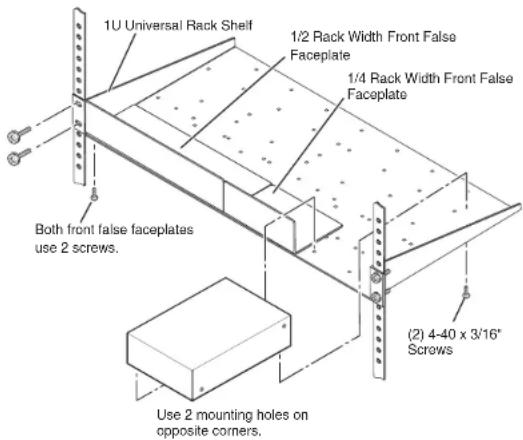
Mounting the AVT 100 on a rack shelf
- Mount the AVT 100 on the rack shelf, using two 4-40 by 3/16" screws in opposite (diagonal) corners to secure the unit to the shelf.
- Install blank panels or other units in the remaining space on the rack shelf.
Installation and Connection, cont'd
Rear Panel Features
The following figure shows the switches and connectors on the rear panel of the AVT 100.

AVT 100 rear panel
① Power connector — Plug the external 12 VDC power supply into this 2-pin, 3.5 mm captive screw connector. The power supply is included with the unit. The figure on the next page shows how to wire the connector.
CAUTION The length of the exposed (stripped) copper wires is important. The ideal length is 3/16" (5 mm). Longer bare wires can short together. Shorter wires are not as secure in the captive screw connectors and could be pulled out.
CAUTION Do not tin the stripped power supply leads before installing the captive screw connector. Tinned wires are not as secure in the captive screw connectors and could be pulled out.
WARNING Keep the two power cord wires separate while plugging in the power supply. Remove power before wiring.
To verify the polarity before connection, plug in the power supply with no load and check the output with a voltmeter.

2-Pole Orange Captive Screw Connector (12V)
Power connector wiring
② Radio frequency (RF) connector — Plug an antenna or CATV cable into the 75 ohm F type female coaxial connector (for NTSC), or into the 75 ohm female IEC 169-2 connector (for PAL).
③ Cable/antenna switch — Use this DIP switch to select between cable (CATV) and antenna (TV) modes. Presets and NTSC Auto-Scan channels are saved separately for antenna and CATV.
④ Composite video output connector — Plug a television or other A/V output device into this female BNC connector.
⑤ Audio connector — Plug an audio output device into this 5-pole captive screw connector. Balanced or unbalanced audio is output on this connector.

Wiring the audio output connector
Installation and Connection, cont'd
CAUTION Connect the sleeve to ground (). Connecting the sleeve to a negative (-) terminal will damage the audio output circuits.
⑥ RS-232/IR connector — Use this five-pole connector for an RS-232 connection to a PC for entering SIS commands and using the Windows-based control software, and/or for connecting the wired IR Link. See "Wiring and Connecting the RS-232 Cable," on the next page, for information on connecting to this port.
⑦ Reserved switch — This is an extra DIP switch that is not used.
⑧ Version label — Indicates the version, PAL or NTSC, of the AVT 100.
Wiring and Connecting the RS-232 Cable
To connect your computer or control system to the RS-232 connector, use a male 9-pin, D-to-bare-wire RS-232 cable or a universal control cable (UC 50', UC 100', or UC 200'). One end of the UC cable is terminated with a female 9-pin, D connector, and the other end is unterminated. Wire the unterminated end to the provided five-pin captive screw plug.
The following diagram shows the UC cable's pin assignments.

UC cable pin assignment color codes
- Wire the RS-232 cable to the five-pole captive screw connector, provided with the AVT 100, as described below (see the illustration on page 2-7). Connect only the red, orange, and green wires in the cable; and use only the first three pins on the connector, starting at the left.
a. Connect the red wire to the first pin on the left, which plugs into the Tx (Transmit) port.
b. Connect the orange wire to the second pin, which plugs into the Rx (Receive) port.
c. Connect the green wire to the third pin, which plugs into the ground port, marked with this symbol: 12
- Plug the five-pole connector into the RS-232/IR receptacle on the AVT 100 rear panel.
The following diagram shows how to connect your PC or control system to the RS-232/IR port.

Wiring the AVT 100 to a PC or control station through the RS-232/IR port
Connecting the AVT 100 to the IR Link
The optional IR Link Infrared Signal Repeater can be connected directly to an AVT 100. To wire the IR Link for use with your AVT 100,
-
Prepare the site and install a wall box, following the directions in the IR Link User's Manual, provided with your IR Link equipment.
-
Cut a length of 150' (45 m) or less of Extron Comm-Link (CTL or CTLP) cable to go between the AVT 100 and the IR Link.
-
Attach a 3.5 mm, 5-pole captive screw connector to each end of the cable. Only three wires (between pins A, B, and D on the IR Link end, and pins Ground, IR, and +12 V on the AVT 100 end) are required. Wire the cable as shown in the illustration on the next page. Connectors are included with the IR Link, but the cable must be purchased separately.
-
Plug the 5-pole connector into one of the IR Link's communications connectors.
Installation and Connection, cont'd
- Plug the other end of the cable into the RS-232/IR port on the rear panel of the AVT 100.
CAUTION
Do not connect more than one IR Link (either in parallel or in series) to a demodulator.

Using the AVT 100 IR Remote with the IR Link
The following diagram shows how to wire the AVT 100 to use the infrared remote control with the optional IR Link.
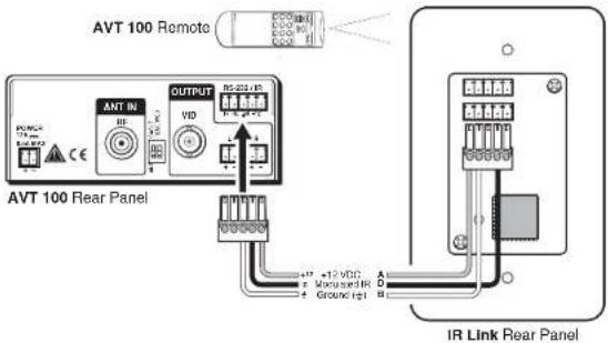
Wiring the IR Link to the AVT 100
NOTE The ground pin is shared between RS-232 control and the IR Link connection.
Connecting the AVT 100 to a MediaLink™ Controller
You can hard wire an MLC MediaLink™ Controller's modulated IR output connector directly to the AVT 100 to provide remote control of the AVT.
Follow these steps to connect the AVT 100 to an MLC. See the diagrams on the next page for examples.
-
Cut a length of 150' (45 m) or less of Extron Comm-Link (CTL or CILP) cable, which will go between the AVT 100 and the MediaLink controller.
-
Attach the provided 3.5 mm, 5-pole connector to the end of the cable that will attach to the AVT 100, connecting one wire to the center pin (which will plug into the AVT's ground connector pin, marked with ± ), and another wire to the pin to the right of the center ground pin. (This pin will plug into the AVT's IR connector.) Plug this end of the cable into the RS-232/IR connector on the AVT's rear panel.
-
On the other (MediaLink controller) end of the cable, do either of the following:
-
Attach the cable's corresponding wires to the ground and IR output pins of the captive screw connector that will plug into the MLC. Plug this end of the cable into the IR connector on the MLC's rear panel.
-
Attach the cable's wires directly to the ground and IR output pins on the MLC's rear panel.
-
Using Global Configurator software, program the MLC with the proper IR drivers for the AVT 100. Refer to your MediaLink controller user's manual for more information.
NOTE If the AVT 100 does not respond to commands from the MediaLink controller, a 1k ohm resistor may be required between the ground and IR pins on the AVT 100.
This resistor is required when you are using an MLC 52 to control the AVT.
Installation and Connection, cont'd

Wiring the AVT 100 to an MLC 52
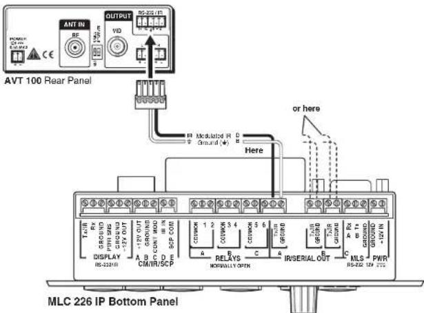
Wiring the AVT 100 to an MLC 226 IP
NOTE The MLC can also control the AVT 100 via an optional IR Emitter. Refer to your MLC user's manual for information on connecting the emitter.

AVT 100
3 Chapter Three
Operation
Front Panel Features
Using the Control Buttons
Special Functions
Using the IR Remote Control for AVT 100
Operation
Front Panel Features
The NTSC and the PAL versions of the AVT 100 have the same front panel with identical components and appearance. The following features and functions are available on the AVT 100 front panel.

AVT 100 front panel
① Digital display — This 3-digit, alphanumeric LED display indicates the antenna TV or CATV channel being received (in Tune mode) or the selected channel preset (in Preset mode).
② IR receiver (not visible from the exterior of the unit) — This sensor receives commands via infrared signals from the optional AVT 100 IR Remote Control.
③ Channel up and down buttons — These push-buttons are used to increment or decrement the channel or preset number. You can also activate Auto-Scan by pressing and holding both of these buttons simultaneously for 2 seconds (see "Initiating Auto-Scan" on the next page).
Using the Control Buttons
Changing the channel
If the AVT 100 is in Tune mode (factory default):
- Press the up or down Channel button to tune to the desired channel. The current channel number is displayed in the 3-digit LED display.
- Press and hold down one of the Channel buttons to change the channels rapidly until the button is released. When the highest channel number available is reached, the display restarts numbering at the lowest channel number.
If the AVT 100 is in Preset mode (available only by SIS command, the Windows-based control software, or the IR remote control), you can change only to a preset channel. To change the preset, press the Channel buttons to display the numbers of the programmed presets in incremental or decremental order.
Initiating Auto-Scan
When Auto-Scan is enabled, the AVT 100 scans all channels and saves to memory those with an active signal.
To initiate automatic scanning, press and hold both Channel buttons. After about 2 seconds, the AVT 100 scans through the channels and saves them to memory.
Adding and deleting channels
Auto-Scanned channels can be added to or removed from memory individually by using SIS commands or the Windows-based control software. (See chapter 4, "Software Configuration and Control," for further information.)
Special Functions
The AVT 100 offers some special functions that are accessible only by using SIS commands, the AVT 100 Remote, and the Windows-based control software. Refer to chapter 4, "Software Configuration and Control," or the AVT 100 help file for the commands to enable these functions.
Locking front panel controls (executive mode)
Executive mode disables all front panel controls, locking out the user from those functions. Putting the AVT 100 in this mode enhances security by protecting against inappropriate or accidental changes to settings.
When the AVT 100 is in executive mode, all serial port commands remain enabled.
When executive mode is enabled, the AVT 100 displays the following message on the digital display for 2 seconds:

Any attempt to use the front panel buttons while the AVT 100 is in executive mode causes the LOC (Locked) message to flash.
Operation, cont'd
When executive mode is disabled, the AVT 100 displays the UNL (Unlocked) message:

Selecting tune or preset mode
Two channel selection modes are available: Tune and Preset. You can use the Windows-based control software, SIS commands, or the AVT 100 Remote to switch between modes.
- In Tune mode, the Channel up and down buttons increment and decrement by one channel with each press of the button. If a button is held down for 2 seconds, the channels tune rapidly up or down until the button is released. Tune mode is the factory default.
- In Preset mode, the Channel buttons step up or down through presets that have been associated with channels via SIS commands, the AVT 100 Remote, or the Windows-based control software.
NOTE Presels can be recalled via SIS commands, the Windows-based control software, or the AVT 100 Remote in both tune mode and presel mode.
Presets
The AVT 100 provides 198 programmable presets—99 for antenna and 99 for cable. Presets are associated with channels by SIS commands (see chapter 4, "Software Configuration and Control"), the AVT 100 Remote (see "Using the IR Remote Control for AVT 100," later in this chapter), or via the Windows-based control software (see the software's help file).
Channel presets that are programmed while the AVT is in either antenna or CATV mode remain exclusive to the mode in which they were saved.
The following table shows the ranges of channel numbers that may be preset.
| NTSC | NTSC Japan | PAL | |||
| DIP Switch | Antenna | Cable Cable | Antenna | Antenna and Cable | |
| Channel # | 2 to 69 | 2 to 125 | 1 to 62 | 1 to 63 | 48 to 885 |
Channels available for presetting
When the AVT 100 is in tune mode and a preset is recalled via the appropriate SIS command, the AVT 100 Remote, or the Windows-based control software, a stored preset recalls the cable or antenna TV channel that was programmed for it. When you select a preset in either tune or preset mode, its preset number is displayed for 2 seconds. Then the display changes to the channel number associated with the selected preset.
Example: If preset 30 is selected via the Channel buttons in Preset mode, the digital display shows the following:
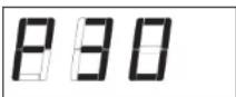
After 2 seconds, the digital display shows the channel number (28 in this example) associated with preset number 30.

To overwrite a preset and change its channel, enter the SIS command or the Windows-based control software selection, or press the appropriate buttons on the IR remote control to save a different channel to that preset number. See chapter 4, "Software Configuration and Control, for information on programming the presets using SIS commands.
Muting the audio and video outputs
Audio and video outputs can be individually muted through the appropriate SIS command, the IR remote control, or the Windows-based control software. (See chapter 4, "Software Configuration and Control" or the AVT 100 help file for further information.)
Selecting the audio output mode
You can select the audio output mode (mono or stereo) using SIS commands or the Windows-based control software. (Mono is the factory default.)
On PAL models, the following four audio selections are available if a dual channel is detected:
- L-L — Select the left audio channel for dual mono output.
- R-R — Select the right audio channel for dual mono output.
Operation, cont'd
• L - R — Select the left input channel for left output and the right input channel for right output.
• R - L — Select the right input channel for left output and the left input channel for right output.
(See chapter 4, "Software Configuration and Control," for information on the SIS commands for audio mode selection. To switch audio output modes using the Windows-based control software, refer to the help file.)
Selecting the PAL broadcasting standard
There are several different PAL broadcasting standards. You can select the appropriate standard using SIS commands (see chapter 4, "Software Configuration and Control) or the Windows-based control software (see the software program's help file).
Selecting the cable TV frequency (NTSC only)
You can select the CATV frequency (Standard, IRC, HRC, or Japan standard) so that your AVT 100 is compatible with the frequency used by your cable provider. You can select the frequency using SIS commands (see chapter 4, "Software Configuration and Control") or the Windows-based control software (see the software program's help file).
Using the IR Remote Control for AVT 100
The optional hand-held AVT 100 IR Remote Control lets you remotely perform many of the functions that are also available through the front panel buttons, SIS commands, and/or the Windows-based control software. The AVT responds to commands from the AVT 100 Remote as if the corresponding button were pressed on the front panel, or the corresponding SIS command or Windows-based control software selection were entered.
From a distance of no more than 30 feet, the remote control sends infrared (IR) signals to the AVT 100 through the tuner's front panel. The IR receiver is located to the right of the channel display, but is not visible from in front of the AVT 100.
The infrared remote receiver can receive the signal if it is sent from within a 40 degree arc to the right or left of direct line of sight between the remote and the AVT 100 receiver. See the diagram below.

Area for remote signal reception
NOTE The AVT 100 must be plugged in before you operate the remote control. Setup operations cannot be performed from the remote.
Locking IR remote access
The AVT 100 Remote Control can be set to lock out users from using it to control the AVT 100. This remote access can be turned on and off via SIS commands or the Windows-based control software. When remote access is set to Off, all AVT 100 controls remain available through other means (SIS commands, Windows-based control software, and the front panel).
Installing batteries in the AVT 100 Remote
Install two AAA batteries in the AVT 100 Remote Control as shown below.

Installing batteries in the AVT 100 Remote
Operation, cont'd
Buttons on the AVT 100 IR Remote Control
The following functions are available through the buttons on the AVT 100 Remote Control.
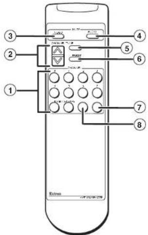
Buttons on the AVT 100 Remote Control
① Channel selection (0 through 9) — In tune mode, press these number buttons to specify a channel number, then press Enter to select it.
In preset mode, pressing these buttons also selects the channel whose number(s) you pressed. The buttons do not select preset numbers.
② Channel up/down — Press the up and down arrows on this rocker button to increment and decrement the channel or preset number.
In tune mode, pressing either part of this button displays the adjacent channel number. If an Auto-Scan has been performed, pressing the Channel button causes the display to cycle between the channels that were set by the scan for the mode (TV or cable) in which the scan was done. (In this case, the adjacent channel may not be available for display.)
In Preset mode, the next or previous preset channel is displayed, depending on which part of the button you pressed. The AVT 100 briefly displays the preset number preceded by a "P," then it displays the channel number associated with that preset.
If no presets have been defined when the Channel button is pressed, the display shows "P00," then the channel number to which the AVT 100 was set before entering preset mode.
NOTE The Channel up/down button applies to antenna (TV) and cable modes. Use the DIP switch on the rear panel to switch between these modes.
③ Video Mute — Press this button to toggle video muting on and off. When muting is on, video output is mute.
④ Audio Mute — Press this button to toggle audio muting on and off. When muting is on, audio output is mute.
⑤ Tune — Press this button to switch to tune mode. In tune mode, the Channel buttons switch between channel numbers.
⑥ Preset — Press this button to switch to preset mode. In preset mode, the Channel buttons switch between preset channels.
⑦ Save — After keying in a preset number, press this button to save the currently selected channel as a preset.
⑧ Enter — After keying in a channel number, press this button to switch to that channel.
Selecting a channel (tuning) using the IR remote
To select or change a channel using the AVT 100 IR Remote Control,
- Using the IR remote channel selection number buttons in the same way you would use the number keys on a calculator, enter the number of the desired channel.
Example: To change to channel 105, press the buttons numbered 1, then 0, then 5.
- Press the Enter button to activate the channel change. If the number you entered is a valid channel, the AVT 100 switches to it, and the number remains displayed on the AVT 100 front panel.
If you enter an invalid (out of range) channel number, after 3 seconds the front panel display returns to the channel number that was displayed previously and does not change the channel.
Operation, cont'd
Saving a preset using the IR remote
To assign a channel number to one of the 198 available presets,
- Switch to the channel that you want to assign. (See "Selecting a channel (tuning) using the IR remote," on the previous page.)
- Enter the preset number to which you want to assign the current channel.
- Press Save. The AVT 100 saves the preset, and displays "P" and the preset number as confirmation. After 3 seconds, the display returns to the channel number that you just saved.
NOTE If an invalid preset number is entered, no preset is saved.

AVT 100
Chapter Four
Software Configuration and Control
Using Simple Instruction Set (SIS™) Commands
Windows®-Based Control Software
Software Configuration and Control
The AVT 100 demodulator can be remotely set up and controlled via a host computer or other device (such as a control system), attached to the rear panel RS-232 port. See chapter 2, "Installation and Connection," for information on connections. The control device (host) can use the Extron Simple Instruction Set (SIS ^™ ) commands or the Windows-based control software.
Using Simple Instruction Set (SIS™) Commands Host-to-AVT communications
SIS commands consist of one or more characters per field. No special characters are required to begin or end a command sequence. You can enter these commands from your PC using a communication software program such as HyperTerminal. When the AVT 100 determines that a command is valid, it executes the command and sends a response to the host device.
Most responses from the AVT 100 to the host (PC) end with a carriage return and a line feed (CR/LF = ↓ which signals the end of the response character string. A string is one or more characters.
AVT 100-initiated messages
When a local event such as a front panel selection takes place, the AVT 100 responds by sending a message to the host, indicating what selection was entered. No response is required from the host. One of the following AVT 100-initiated messages is displayed, depending on your version.
NOTE
These messages are displayed only at power-up.
NOTE
For the x4 and x1 values shown below, see "Symbol definitions" on page 4-4.
NTSC version:
(C) Copyright 2006, Extron Electronics, AVT 100 - NTSC Version, Vx.xx
Dip x4
TVC
PAL version:
(C) Copyright 2005, Extron Electronics, AVT 100 – PAL Version, Vx.xx
Dip X4
TVC x1
The AVT 100 sends the copyright message when it first powers on. Vx.xx is the firmware version number.
Error responses
If the AVT 100 is unable to execute a command it receives because the command is invalid or contains invalid parameters, the AVT returns an error response to the host. Error response codes and their descriptions are as follows:
E01 - Invalid input channel number (out of range)
E10 - Invalid command
E11 - Invalid preset
E13 – Invalid value (out of range)
Using the command/response tables
The command/response tables on the following pages list valid command ASCII and hexadecimal codes, the AVT 100's responses to the host, and a description of the command's function or the results of executing the command.
The ASCII to HEX conversion table below is for use with the command/response tables.
| ASCII to HEX Conversion Table | Esc 1B | CR 0D | LF 0A | ||||||
| 20 | ! | 21 | * | 22 | # | 23 | S 24 | % 25 | & 26 |
| ( 28 ) | ) | 29 | * | 2A | + | 2B | , 2C | - 2D | - 2E |
| ∅ 30 | 1 | 31 | 2 | 32 | 3 | 33 | 4 34 | 5 35 | 6 36 |
| 8 38 | 9 | 39 | : | 3A | ; | 3B | < 3C | = 3D | > 3E |
| @ 40 | A | 41 | B | 42 | C | 43 | D 44 | E 45 | F 46 |
| H 48 | I | 49 | J | 4A | K | 4B | L 4C | M 4D | N 4E |
| P 50 | Q | 51 | R | 52 | S | 53 | T 54 | U 55 | V 56 |
| X 58 | Y | 59 | Z | 5A | [ | 5B | \ 5C] | 5D | ^ 5E |
| . 60 | a | 61 | b | 62 | c | 63 | d 64 | e 65 | f 66 |
| h 68 | i | 69 | j | 6A | k | 6B | l 6C | m 6D | n 6E |
| p 70 | q | 71 | r | 72 | s | 73 | t 74 | u 75 | v 76 |
| x 78 | y | 79 | z | 7A | { | 7B | l 7C} | 7D | - 7E |
Software Configuration and Control, cont'd
Symbol definitions
= CR/LF (carriage return/line feed) (hex 0D 0A)
← = Soft carriage return (no line feed)
- = Space
Esc = Escape key
X1 = Channel number NTSC antenna: 002 - 069 NTSC cable: 002 - 125 NTSC Japan antenna: 001-062 NTSC Japan cable: 001-063 PAL antenna and cable: 48 - 855
X2 = Muting/Executive mode 0 = Off 1 = On
X3 = Presets 1 - 99 (The preset number cannot be more than two digits.)
X4 = Antenna or cable DIP switch setting 0 = Antenna (TV) 1 = CATV (cable)
X5 = PAL standard selection 0 = B/G (default) 1 = D/K 2 = 1
XE = Part number
X7 = Audio adjustment level: -63 through +12
= Gain level: 0 - 12
x9 = Attenuation level: 0 - 63
NOTE
If a command is not case-sensitive, this is indicated by showing the command letter in uppercase, followed by a slash (i), then the same letter in lowercase.
Examples: B/b, Z/z
Command/response table for SIS commands
| Command ASCII Response Additional(host to AVT) (AVT to host) | information | ||
| Memory preset | |||
| Save preset (active channel) | x3, Spr | x3 ↓ | x3 = Presets 01-99. |
| Recall preset | x3, Rpr | x3 chn x1 ↓ | |
| Save preset (user-specified channel) | x1 * x3, pre | x3 chn x1 ↓ | x1 channel values:NTSC antenna: 002-069NTSC CATV: 002-125PAL antenna (TV) and CATV:048-855 |
| View all presets | Esc .← | pre01chnxxx ↓ through pre99chnxxx ↓ | |
| Video mute | |||
| Mute on 1B/b Vmt | x2 ↓ | Mutes video output.For x2: 0 = off; 1 = on. | |
| Mute off 0B/b Vmt | x2 ↓ | Unmutes video output. | |
| View video mute status B/b Vmt | x2 ↓ | Shows muting status. | |
| Audio mute | |||
| Mute on 1Z/z Amt | x2 ↓ | Mutes audio output. | |
| Mute off 0Z/z Amt | x2 ↓ | Unmutes audio output. | |
| View the audio mute status Z/z Amt | x2 ↓ | Shows muting status. | |
| Command ASCII Response Additional(host to AVT) | (AVT to host) | information | |
| PAL standard selection (PAL version only) | |||
| Select standard | xs S/s | Sys xe ← | Select PAL standard.x5 values are:0 = B/G (default).1 = D/K.2 = I. |
| View status | S/s | Sys x6 ← | Show the current PAL standard. |
| Request information | |||
| Request channel number | I/i | TVC x1 ← | x1 = channel number. |
| Audio gain and attenuation (NTSC model only) | |||
| Set specific gain | x0 G | Aud x7 ← | Set the gain to x7 dB.Range for gain (x8) is 0 to +12. |
| Set specific attenuation | x9 g | Aud x7 ← | Set the attenuation to x7 dB.Range for attenuation (x9) is 0 to +63. |
| Increment gain or attenuation | -G/g | Aud x7 ← | Set audio level to x7 dB by increasing gain or attenuation.Default audio level is 0dB. |
| Decrement gain or attenuation | -G/g Aud | x7 ← | Set audio level to x7 dB by decreasing gain or attenuation. |
| View gain or attenuation | G/g | x7 ← | View current audio level in dB. |
Command/response table for SIS commands (continued)
| Command ASCII Response Additional information(host to AVT 100) (AVT 100 to host) | |||
| Executive mode | |||
| Disable 0X/x Exe0 Enables control via the front panel | ↓ | by disabling executive mode. | |
| Enable 1X/x Exe1 | ↓ | Locks out control from thefront panel. | |
| View Status X/x Exe | x2 Shows whether executive mode is onor off. | ||
| Query firmware version | |||
| Query firmware version Q/q x.xx Shows current firmware | ↓ | version. x.xx is the format of theversion number. | |
| Request Part Number | |||
| Request AVT 100 part number | N/n | x5 ↓ | x6 values:NTSC = 60-647-01.PAL. = 60-647-02. |
| Reset to default settings (Zap command) | |||
| Zap settings/memories | zXXX← | ZapXXX← | The default settings are:Tune modeAll presets removedAuto-Scan channels cleared |
Software Configuration and Control, cont'd
Command/response table for special function SIS commands
The syntax for initiating a special function is:
[X!] * _ #
where _ is the function number and ! is the value.
To view a function's setting, use:
__#
where _ is the function number.
In the following special functions command table, the values of the variable are different for each command/function. These values are given in the far right column.
Command/response table for special function SIS commands
| Command ASCII command Response (host to AVT) (AVT to host) and additional descriptions | |||
| Preset and Tune modes | |||
| Select mode | 1 * 1 \# Mod | 1 = Preset. | 1 = Tune. |
| Example: 1 * 1 # Mod 1 | Enable Tune Mode. | ||
| View 1 # Mod | 1 | ||
| Auto-Scan | |||
| Activate Auto-Scan 2 # Scr Same function as holding down both channel | buttons on the front panel | ||
| Delete Auto-Scan channel | 1 * 3 \# Del | 1 | 1 values for NTSC:002-069 (antenna TV channel)002-125 (CATV channel) 1 values for NTSC Japan:001-062 (antenna TV channel)001-063 (CATV channel) 1 values for PAL:048-855 (antenna and CATV channel)(1, 2, or 3 digits may be entered.) |
| Example: 011 * 3 # Del 011 | Delete channel 11. | ||
| Add Auto-Scan Channel | 1 * 4 \# Add | 1 | 1 values for NTSC:002-069 (TV channel) (001-062 Japan)002-125 (CATV channel) (001-063 Japan) 1 values for PAL:048-855 (antenna and CATV channel) |
| Example: 011 * 4 # Add 011 | Add channel 11. | ||
| Command | ASCII command(host to AVT) | Response(AVT to host) and additional descriptions | |
| Presets | |||
| Delete presetExample: | 1 * 5\# Del25 * 5 # | 1 Del 025 | 1-99 presets each for cable and TVDelete preset 25. |
| Change channel | |||
| Increment channel | +6 # | TVC 1 | 1 values for NTSC:002-069 (TV channel)002-125 (cable channel) 1 values for NTSC in Japan:001-062 (antenna TV channel)001-063 (CATV channel) 1 values for PAL:048-855 (antenna and CATV channel) |
| Decrement channel | -6 # | TVC 1 See | 1 values for decrementing the channel. |
| Set TV ChannelExample: | 1 * 6\# TVC056 * 6 # | 1 SeeTVC 056 | 1 values for setting the channel.Set TV channel to 56. |
| View channel | 6 # TVC | 1 | |
| View DIP switch setting | |||
| Antenna/cable selection | 8 # | Dip 1 | Shows whether the AVT is set to antenna(TV) or CATV (cable) mode.For 1 0 = Antenna.1 = Cable. |
| Example: | 8 # | Dip1 | DIP switch has been set to cable. |
Command/response table for special function SIS commands (continued)
| Command ASCII command Response(host to AVT) (AVT to host) and additional descriptions | ||
| Audio configuration | ||
| Audio output mode | x1 * 7 # Mon | x1 ⇧= Stereo. |
Command/response table for special function SIS commands (continued)
| Command ASCII command Response (host to AVT 100) (AVT 100 to host) and additional descriptions | xl values | ||
| View Auto-Scan channels | |||
| View all channels 0*10# chn002 • | xl List all channels. chn003 • xl ← Enable. . 0 = Disable. | ||
| View specific channel | xl *10# | xl ← | Show a specified channel. For xl: 0 = Off. 1 = On. [xl] = Channel #. |
| CATV frequency selection (NTSC model only) | |||
| Set frequency | xl * 11# | Cbl xl | Select the set of frequencies used by your cable company: For xl: 1 = IRC. 2 = HRC. 3 = Standard (default). 4 = Japan standard. |
| View frequency setting | 11# | Cbl[xl] | |
Advanced Instruction Set commands
The advanced instructions use hexadecimal commands that are more complex than the Simple Instruction Set. They are used by the Windows-based control program and special third party applications.
Command/response table for Advanced Instruction Set commands
| Command Hex command Response Additional information(host to AVT 100) (AVT 100 to host) | |
| Read/write entire memory (to back up or restore the system) | |
| Read all memory contents 90 91 xxxx bytes of data + 1 byte checksum | Uploads all channels saved, active channel, presets, mode selection, and audio settings. |
| Write all memory contents 90 92 + xxxx bytes of data + 1 byte checksum | Downloads all channels saved, the active channel, presets, mode selection, and audio settings. |
Software Configuration and Control, cont'd
Windows®-Based Control/Configuration Software
In addition to the SIS commands, the AVT 100 Windows-based control/configuration software provides you with another means of configuring and controlling the AVT 100 via RS-232.
This program includes the functions found on the AVT's front panel and the IR remote control, and some additional features that are available only through the Windows-based software or the SIS commands.
Compatibility
The software is compatible with Microsoft ^® Windows 98, Windows NT, Windows 2000, and Windows XP.
Installing the software
Extron's AVT 100 Windows-based software program is provided on a CD with the AVT. You can obtain additional copies of the software at no extra charge and download updates from the Extron Web site at http://www.extron.com.
The Windows-based control software program requires a minimum of 2.5 MB (megabytes) of hard disk space.
To use the software that is on the CD, you must install the program on your computer. Follow these steps:
-
Insert CD ROM Disk B into your CD drive. The disk should open automatically. If it does not, double-click LAUNCH.EXE on the CD to start it.
-
On the "Extron Software Products Disc B: Issue 2007.x" screen, click the Software button, shown at right.
-
On the Control Software screen, click the AVT 100's Install link (outlined in the illustration on the next page).

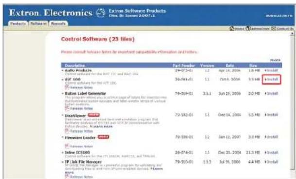
Software Installation screen on CD
- On the File Download window that appears, click Run to begin installing the program.
NOTE
If you want to save the installation file (AVT100Setupv3_n.exe) to your desktop, click Save. On the Save As window, save the setup file to the desired location on your computer. When you are ready to install the software, double-click on the AVT100Setupv3_n.exe icon and follow the directions on the screens.
-
A Security prompt appears. Click Run on this window to continue with the installation.
-
Follow the instructions on the InstallShield Wizard screens to complete the program installation.
By default the installation creates a folder called "AVT 100" in the following location on the computer:
c:\Program Files\Extron\AVT 100
If there is no Extron folder in your Program Files folder, the installation program creates it as well.
Software Configuration and Control, cont'd
Starting the software program
Some items found in the software program correspond directly to the front panel or remote controls. (See chapter 3,
"Operation," for front panel and IR remote control features and settings.) Other features are accessible only through the software or SIS commands (discussed earlier in this chapter).
The AVT 100 Help program provides complete information on settings and on how to use the software.
- To run the program, double-click on the AVT 100.exe file icon, shown at right.

The Extron AVT 100 window appears, with all objects grayed out. The Communication Setup window is displayed in front of it.

AVT 100 window with Communication Setup dialog box
-
From the Port drop-down menu, select the communications port that is connected to your tuner's Config/RS-232 port.
-
Click Connect. The currently selected channel number appears in the Channel box, and all menu options (except Connect) become available. The AVT 100 window's status bar at the bottom of the screen indicates your AVT's configuration — NTSC or PAL.


AVT 100 window, connected (PAL and NTSC versions)
You are now ready to configure presets, select channels, and perform the other tasks available from the pull-down menus, check boxes, and the TV/Cable Channel field on the AVT 100 window.
NOTE
The TV/Cable Channel field is titled "TV Channel" or "Cable Channel," depending on the position of the Antenna/Cable DIP switch on the rear panel.
Using the Windows-based control software help file
The AVT 100 Windows-based control software contains a help program, which explains all menu options, buttons, and functions that are accessible from the AVT 100 window.
To open the help file, select Contents... from the Help pull-down menu on the AVT 100 window, or press the F1 key on your computer keyboard.
Software Configuration and Control, cont'd

AVT 100
Appendix A
Specifications, Parts, and Accessories
Specifications
Models
Included Parts
Optional Accessories
Specifications, Parts, and Accessories
Specifications
RF video input
Number/signal type .... 1 radio frequency (RF)
Connectors
NTSC model ...... 1 female F connector
PAL model ...... 1 female IEC 169-2, 75 ohm connector
Sensitivity -20 to +20 dBmV
Frequency range 55 MHz to 855 MHz
NTSC over the air TV channels. 2-69
Japan 1-62
NTSC CATV cable channels ..... 2-125
Japan 1-63
PAL over the air TV and cable channels 48 MHz to 855 MHz
Impedance 75 ohms
Vertical frequency
NTSC model 60 Hz
PAL model 50 Hz
Video output
Number/signal type ...... 1 composite video
Connectors 1 BNC female
Nominal level 1 Vp-p for composite video
Minimum/maximum levels ..... 0.4 V to 1.0 Vp-p (follows input)
Impedance 75 ohms
DC offset ....±10 mV with input at 0 offset
Sync
Standards
NTSC model .... NTSC 3.58
International model ..... PAL
Audio
THD + Noise ..... NTSC: 0.4% @ 1 kHz
PAL: 0.6% @ 1 kHz
S/N NTSC: -55 dB @ 1 kHz
PAL: -58 dB @ 1 kHz
Stereo channel separation ....>35 dB @ 1 kHz
RF audio input
Number/signal type .... 1 (as part of the RF signal)
NOTE 0 dBu = 0.775 Vrms, 0 dBV = 1 Vrms, 0 dBV ≈ 2 dBu
Audio output
Number/signal type .... 1 balanced/unbalanced; stereo for NTSC, PAL B/G, PAL D/K; mono only for PAL I
Connectors (1) 3.5 mm captive screw connector, 5 pole
Impedance 50 ohms unbalanced, 100 ohms balanced
Gain error.... ± 0.5 dB channel to channel
Nominal level 0 dBu
Output level.... 1 Vrms (max.)
Control/remote — AVT 100
Serial control port .... RS-232; 3.5 mm captive screw connector, 5 pole
Baud rate and protocol ..... 9600 baud, 8 data bits, 1 stop bit, no parity
Serial/IR control pin configurations 1 = TX, 2 = RX, 3 = GND, 4 = modulated IR, 5 = +12 VDC
IR controller module ...... AVT Remote (optional)
30' maximum, 40 degrees off axis
Program control .... Extron's control/configuration program for Windows ^®
Extron's Simple Instruction Set (SIS ^TM )
General
External power supply .... 100 VAC to 240 VAC, 50/60 Hz, external, autoswitchable; to 12 VDC, 1 Λ (max.), regulated
Power input requirements ..... 12 VDC, 0.5 A
Temperature/humidity .... Storage: -40 to +158 °F (-40 to +70 °C) / 10% to 90%, noncondensing Operating: +32 to +122 °F (0 to +50 °C) / 10% to 90%, noncondensing
Cooling ...... Convection, unvented
Rack mount..... Yes, with optional 1U, 9.5" deep rack shelf, (RSU 129, part #60-190-01 or RSB 129, #60-604-01)
Enclosure type ...... Metal
Specifications, Parts, and Accessories, cont'd
| Enclosure dimensions | 1.7" H x 4.3" W x 6.7" D (1U high, quarter rack wide) |
| 4.3 cm H x 10.9 cm W x 17.0 cm D (Depth excludes connectors.) | |
| Product weight | 0.8 lbs (0.4 kg) |
| Shipping weight | 3 lbs (2 kg) |
| Vibration | ISTA 1A in carton (International Safe Transit Association) |
| Compliances | CE, FCC Class A, VCCI, AS/NZS, ICES |
| MTBF | 30,000 hours |
| Warranty | 3 years parts and labor |
NOTE All nominal levels are at ±10%.
NOTE Specifications are subject to change without notice.
Models
| Model Part number |
| AVT 100 - NTSC Version 60-647-01 |
| AVT 100 - PAL Version 60-647-02 |
Included Parts
These items are included in each order for an AVT 100:
| Item Part number |
| Windows-based control software on disk |
| Power cord |
| Tweeker (small screwdriver) |
| Rubber feet (not attached) |
| AVT 100 User's Manual |
| External power supply |
| 5-pole captive screw connector 10-319-10LF |
Optional Accessories
These items can be ordered separately:
| Accessory Part number | |
| 1U, 9.5" Deep RSU 129 Universal Rack 60-190-01Shelf Kit | |
| 1U, 9.5" Deep RSB 129 Basic Rack Shelf 60-604-01 | |
| AVT 100 IR Remote kit 70-366-01 | |
| IR Link (black, white, RAL9010 white) 60-404-02, -03,-05 | |
| CTL Series Comm-Link cable 22-148-02, -03 | |
| CTLP Series Comm-Link cable | 22-119-xx22-461-xx |
Specifications, Parts, and Accessories, cont'd

AVT 100
Appendix B
Channel Frequencies
PAL Format Channels
NTSC Format Channels
Channel Frequencies
PAL Format Channels
The table on the following pages lists all the antenna and CATV channels that are available through the AVT 100 in areas using the PAL standard.
The AVT 100 display shows only whole numbers; it does not show decimal fractions. Therefore, when a PAL channel number is displayed, it does not reflect the exact frequency of that channel. To find out the exact tuning frequency for a PAL channel, locate the channel number in the Channel column, then find its frequency (stated in MHz) beside it in the Freq (MHz) column.
Example: The frequency for channel 82 is 82.25 MHz.
PAL channels
| Channel Freq (MHz) Channel Freq (MHz) Channel Freq (MHz) | |||||
| 48 | 48.25 | 93 | 93.25 | 138 | 138.25 |
| 49 | 49.25 | 94 | 94.25 | 139 | 139.25 |
| 50 | 50.25 | 95 | 95.25 | 140 | 140.25 |
| 51 | 51.25 | 96 | 96.25 | 141 | 141.25 |
| 52 | 52.25 | 97 | 97.25 | 142 | 142.25 |
| 53 | 53.25 | 98 | 98.25 | 143 | 143.25 |
| 54 | 54.25 | 99 | 99.25 | 144 | 144.25 |
| 55 | 55.25 | 100 | 100.25 | 145 | 145.25 |
| 56 | 56.25 | 101 | 101.25 | 146 | 146.25 |
| 57 | 57.25 | 102 | 102.25 | 147 | 147.25 |
| 58 | 58.25 | 103 | 103.25 | 148 | 148.25 |
| 59 | 59.25 | 104 | 104.25 | 149 | 149.25 |
| 60 | 60.25 | 105 | 105.25 | 150 | 150.25 |
| 61 | 61.25 | 106 | 106.25 | 151 | 151.25 |
| 62 | 62.25 | 107 | 107.25 | 152 | 152.25 |
| 63 | 63.25 | 108 | 108.25 | 153 | 153.25 |
| 64 | 64.25 | 109 | 109.25 | 154 | 154.25 |
| 65 | 65.25 | 110 | 110.25 | 155 | 155.25 |
| 66 | 66.25 | 111 | 111.25 | 156 | 156.25 |
| 67 | 67.25 | 112 | 112.25 | 157 | 157.25 |
| 68 | 68.25 | 113 | 113.25 | 158 | 158.25 |
| 69 | 69.25 | 114 | 114.25 | 159 | 159.25 |
| 70 | 70.25 | 115 | 115.25 | 160 | 160.25 |
| 71 | 71.25 | 116 | 116.25 | 161 | 161.25 |
| 72 | 72.25 | 117 | 117.25 | 162 | 162.25 |
| 73 | 73.25 | 118 | 118.25 | 163 | 163.25 |
| 74 | 74.25 | 119 | 119.25 | 164 | 164.25 |
| 75 | 75.25 | 120 | 120.25 | 165 | 165.25 |
| 76 | 76.25 | 121 | 121.25 | 166 | 166.25 |
| 77 | 77.25 | 122 | 122.25 | 167 | 167.25 |
| 78 | 78.25 | 123 | 123.25 | 168 | 168.25 |
| 79 | 79.25 | 124 | 124.25 | 169 | 169.25 |
| 80 | 80.25 | 125 | 125.25 | 170 | 170.25 |
| 81 | 81.25 | 126 | 126.25 | 171 | 171.25 |
| 82 | 82.25 | 127 | 127.25 | 172 | 172.25 |
| 83 | 83.25 | 128 | 128.25 | 173 | 173.25 |
| 84 | 84.25 | 129 | 129.25 | 174 | 174.25 |
| 85 | 85.25 | 130 | 130.25 | 175 | 175.25 |
| 86 | 86.25 | 131 | 131.25 | 176 | 176.25 |
| 87 | 87.25 | 132 | 132.25 | 177 | 177.25 |
| 88 | 88.25 | 133 | 133.25 | 178 | 178.25 |
| 89 | 89.25 | 134 | 134.25 | 179 | 179.25 |
| 90 | 90.25 | 135 | 135.25 | 180 | 180.25 |
| 91 | 91.25 | 136 | 136.25 | 181 | 181.25 |
| 92 | 92.25 | 137 | 137.25 | 182 | 182.25 |
Channel Frequencies, cont'd
PAL channels (continued)
| Channel Freq (MHz) Channel Freq (MHz) Channel Freq (MHz) | |||||
| 183 | 183.25 | 228 | 228.25 | 273 | 273.25 |
| 184 | 184.25 | 229 | 229.25 | 274 | 274.25 |
| 185 | 185.25 | 230 | 230.25 | 275 | 275.25 |
| 186 | 186.25 | 231 | 231.25 | 276 | 276.25 |
| 187 | 187.25 | 232 | 232.25 | 277 | 277.25 |
| 188 | 188.25 | 233 | 233.25 | 278 | 278.25 |
| 189 | 189.25 | 234 | 234.25 | 279 | 279.25 |
| 190 | 190.25 | 235 | 235.25 | 280 | 280.25 |
| 191 | 191.25 | 236 | 236.25 | 281 | 281.25 |
| 192 | 192.25 | 237 | 237.25 | 282 | 282.25 |
| 193 | 193.25 | 238 | 238.25 | 283 | 283.25 |
| 194 | 194.25 | 239 | 239.25 | 284 | 284.25 |
| 195 | 195.25 | 240 | 240.25 | 285 | 285.25 |
| 196 | 196.25 | 241 | 241.25 | 286 | 286.25 |
| 197 | 197.25 | 242 | 242.25 | 287 | 287.25 |
| 198 | 198.25 | 243 | 243.25 | 288 | 288.25 |
| 199 | 199.25 | 244 | 244.25 | 289 | 289.25 |
| 200 | 200.25 | 245 | 245.25 | 290 | 290.25 |
| 201 | 201.25 | 246 | 246.25 | 291 | 291.25 |
| 202 | 202.25 | 247 | 247.25 | 292 | 292.25 |
| 203 | 203.25 | 248 | 248.25 | 293 | 293.25 |
| 204 | 204.25 | 249 | 249.25 | 294 | 294.25 |
| 205 | 205.25 | 250 | 250.25 | 295 | 295.25 |
| 206 | 206.25 | 251 | 251.25 | 296 | 296.25 |
| 207 | 207.25 | 252 | 252.25 | 297 | 297.25 |
| 208 | 208.25 | 253 | 253.25 | 298 | 298.25 |
| 209 | 209.25 | 254 | 254.25 | 299 | 299.25 |
| 210 | 210.25 | 255 | 255.25 | 300 | 300.25 |
| 211 | 211.25 | 256 | 256.25 | 301 | 301.25 |
| 212 | 212.25 | 257 | 257.25 | 302 | 302.25 |
| 213 | 213.25 | 258 | 258.25 | 303 | 303.25 |
| 214 | 214.25 | 259 | 259.25 | 304 | 304.25 |
| 215 | 215.25 | 260 | 260.25 | 305 | 305.25 |
| 216 | 216.25 | 261 | 261.25 | 306 | 306.25 |
| 217 | 217.25 | 262 | 262.25 | 307 | 307.25 |
| 218 | 218.25 | 263 | 263.25 | 308 | 308.25 |
| 219 | 219.25 | 264 | 264.25 | 309 | 309.25 |
| 220 | 220.25 | 265 | 265.25 | 310 | 310.25 |
| 221 | 221.25 | 266 | 266.25 | 311 | 311.25 |
| 222 | 222.25 | 267 | 267.25 | 312 | 312.25 |
| 223 | 223.25 | 268 | 268.25 | 313 | 313.25 |
| 224 | 224.25 | 269 | 269.25 | 314 | 314.25 |
| 225 | 225.25 | 270 | 270.25 | 315 | 315.25 |
| 226 | 226.25 | 271 | 271.25 | 316 | 316.25 |
| 227 | 227.25 | 272 | 272.25 | 317 | 317.25 |
PAL channels (continued)
| Channel Freq (MHz) Channel | Freq (MHz) | Channel Freq (MHz) | |||
| 318 | 318.25 | 363 | 363.25 | 408 | 408.25 |
| 319 | 319.25 | 364 | 364.25 | 409 | 409.25 |
| 320 | 320.25 | 365 | 365.25 | 410 | 410.25 |
| 321 | 321.25 | 366 | 366.25 | 411 | 411.25 |
| 322 | 322.25 | 367 | 367.25 | 412 | 412.25 |
| 323 | 323.25 | 368 | 368.25 | 413 | 413.25 |
| 324 | 324.25 | 369 | 369.25 | 414 | 414.25 |
| 325 | 325.25 | 370 | 370.25 | 415 | 415.25 |
| 326 | 326.25 | 371 | 371.25 | 416 | 416.25 |
| 327 | 327.25 | 372 | 372.25 | 417 | 417.25 |
| 328 | 328.25 | 373 | 373.25 | 418 | 418.25 |
| 329 | 329.25 | 374 | 374.25 | 419 | 419.25 |
| 330 | 330.25 | 375 | 375.25 | 420 | 420.25 |
| 331 | 331.25 | 376 | 376.25 | 421 | 421.25 |
| 332 | 332.25 | 377 | 377.25 | 422 | 422.25 |
| 333 | 333.25 | 378 | 378.25 | 423 | 423.25 |
| 334 | 334.25 | 379 | 379.25 | 424 | 424.25 |
| 335 | 335.25 | 380 | 380.25 | 425 | 425.25 |
| 336 | 336.25 | 381 | 381.25 | 426 | 426.25 |
| 337 | 337.25 | 382 | 382.25 | 427 | 427.25 |
| 338 | 338.25 | 383 | 383.25 | 428 | 428.25 |
| 339 | 339.25 | 384 | 384.25 | 429 | 429.25 |
| 340 | 340.25 | 385 | 385.25 | 430 | 430.25 |
| 341 | 341.25 | 386 | 386.25 | 431 | 431.25 |
| 342 | 342.25 | 387 | 387.25 | 432 | 432.25 |
| 343 | 343.25 | 388 | 388.25 | 433 | 433.25 |
| 344 | 344.25 | 389 | 389.25 | 434 | 434.25 |
| 345 | 345.25 | 390 | 390.25 | 435 | 435.25 |
| 346 | 346.25 | 391 | 391.25 | 436 | 436.25 |
| 347 | 347.25 | 392 | 392.25 | 437 | 437.25 |
| 348 | 348.25 | 393 | 393.25 | 438 | 438.25 |
| 349 | 349.25 | 394 | 394.25 | 439 | 439.25 |
| 350 | 350.25 | 395 | 395.25 | 440 | 440.25 |
| 351 | 351.25 | 396 | 396.25 | 441 | 441.25 |
| 352 | 352.25 | 397 | 397.25 | 442 | 442.25 |
| 353 | 353.25 | 398 | 398.25 | 443 | 443.25 |
| 354 | 354.25 | 399 | 399.25 | 444 | 444.25 |
| 355 | 355.25 | 400 | 400.25 | 445 | 445.25 |
| 356 | 356.25 | 401 | 401.25 | 446 | 446.25 |
| 357 | 357.25 | 402 | 402.25 | 447 | 447.25 |
| 358 | 358.25 | 403 | 403.25 | 448 | 448.25 |
| 359 | 359.25 | 404 | 404.25 | 449 | 449.25 |
| 360 | 360.25 | 405 | 405.25 | 450 | 450.25 |
| 361 | 361.25 | 406 | 406.25 | 451 | 451.25 |
| 362 | 362.25 | 407 | 407.25 | 452 | 452.25 |
Channel Frequencies, cont'd
PAL channels (continued)
| Channel Freq (MHz) Channel Freq (MHz) Channel Freq (MHz) | |||||
| 453 | 453.25 | 498 | 498.25 | 543 | 543.25 |
| 454 | 454.25 | 499 | 499.25 | 544 | 544.25 |
| 455 | 455.25 | 500 | 500.25 | 545 | 545.25 |
| 456 | 456.25 | 501 | 501.25 | 546 | 546.25 |
| 457 | 457.25 | 502 | 502.25 | 547 | 547.25 |
| 458 | 458.25 | 503 | 503.25 | 548 | 548.25 |
| 459 | 459.25 | 504 | 504.25 | 549 | 549.25 |
| 460 | 460.25 | 505 | 505.25 | 550 | 550.25 |
| 461 | 461.25 | 506 | 506.25 | 551 | 551.25 |
| 462 | 462.25 | 507 | 507.25 | 552 | 552.25 |
| 463 | 463.25 | 508 | 508.25 | 553 | 553.25 |
| 464 | 464.25 | 509 | 509.25 | 554 | 554.25 |
| 465 | 465.25 | 510 | 510.25 | 555 | 555.25 |
| 466 | 466.25 | 511 | 511.25 | 556 | 556.25 |
| 467 | 467.25 | 512 | 512.25 | 557 | 557.25 |
| 468 | 468.25 | 513 | 513.25 | 558 | 558.25 |
| 469 | 469.25 | 514 | 514.25 | 559 | 559.25 |
| 470 | 470.25 | 515 | 515.25 | 560 | 560.25 |
| 471 | 471.25 | 516 | 516.25 | 561 | 561.25 |
| 472 | 472.25 | 517 | 517.25 | 562 | 562.25 |
| 473 | 473.25 | 518 | 518.25 | 563 | 563.25 |
| 474 | 474.25 | 519 | 519.25 | 564 | 564.25 |
| 475 | 475.25 | 520 | 520.25 | 565 | 565.25 |
| 476 | 476.25 | 521 | 521.25 | 566 | 566.25 |
| 477 | 477.25 | 522 | 522.25 | 567 | 567.25 |
| 478 | 478.25 | 523 | 523.25 | 568 | 568.25 |
| 479 | 479.25 | 524 | 524.25 | 569 | 569.25 |
| 480 | 480.25 | 525 | 525.25 | 570 | 570.25 |
| 481 | 481.25 | 526 | 526.25 | 571 | 571.25 |
| 482 | 482.25 | 527 | 527.25 | 572 | 572.25 |
| 483 | 483.25 | 528 | 528.25 | 573 | 573.25 |
| 484 | 484.25 | 529 | 529.25 | 574 | 574.25 |
| 485 | 485.25 | 530 | 530.25 | 575 | 575.25 |
| 486 | 486.25 | 531 | 531.25 | 576 | 576.25 |
| 487 | 487.25 | 532 | 532.25 | 577 | 577.25 |
| 488 | 488.25 | 533 | 533.25 | 578 | 578.25 |
| 489 | 489.25 | 534 | 534.25 | 579 | 579.25 |
| 490 | 490.25 | 535 | 535.25 | 580 | 580.25 |
| 491 | 491.25 | 536 | 536.25 | 581 | 581.25 |
| 492 | 492.25 | 537 | 537.25 | 582 | 582.25 |
| 493 | 493.25 | 538 | 538.25 | 583 | 583.25 |
| 494 | 494.25 | 539 | 539.25 | 584 | 584.25 |
| 495 | 495.25 | 540 | 540.25 | 585 | 585.25 |
| 496 | 496.25 | 541 | 541.25 | 586 | 586.25 |
| 497 | 497.75 | 542 | 542.25 | 587 | 587.25 |
PAL channels (continued)
| Channel Freq (MHz) | Channel Freq (MHz) | Channel Freq (MHz) | Channel Freq (MHz) | |
| 588 | 588.25 | 633 | 633.25 | 678 |
| 589 | 589.25 | 634 | 634.25 | 679 |
| 590 | 590.25 | 635 | 635.25 | 680 |
| 591 | 591.25 | 636 | 636.25 | 681 |
| 592 | 592.25 | 637 | 637.25 | 682 |
| 593 | 593.25 | 638 | 638.25 | 683 |
| 594 | 594.25 | 639 | 639.25 | 684 |
| 595 | 595.25 | 640 | 640.25 | 685 |
| 596 | 596.25 | 641 | 641.25 | 686 |
| 597 | 597.25 | 642 | 642.25 | 687 |
| 598 | 598.25 | 643 | 643.25 | 688 |
| 599 | 599.25 | 644 | 644.25 | 689 |
| 600 | 600.25 | 645 | 645.25 | 690 |
| 601 | 601.25 | 646 | 646.25 | 691 |
| 602 | 602.25 | 647 | 647.25 | 692 |
| 603 | 603.25 | 648 | 648.25 | 693 |
| 604 | 604.25 | 649 | 649.25 | 694 |
| 605 | 605.25 | 650 | 650.25 | 695 |
| 606 | 606.25 | 651 | 651.25 | 696 |
| 607 | 607.25 | 652 | 652.25 | 697 |
| 608 | 608.25 | 653 | 653.25 | 698 |
| 609 | 609.25 | 654 | 654.25 | 699 |
| 610 | 610.25 | 655 | 655.25 | 700 |
| 611 | 611.25 | 656 | 656.25 | 701 |
| 612 | 612.25 | 657 | 657.25 | 702 |
| 613 | 613.25 | 658 | 658.25 | 703 |
| 614 | 614.25 | 659 | 659.25 | 704 |
| 615 | 615.25 | 660 | 660.25 | 705 |
| 616 | 616.25 | 661 | 661.75 | 706 |
| 617 | 617.25 | 662 | 662.25 | 707 |
| 618 | 618.25 | 663 | 663.25 | 708 |
| 619 | 619.25 | 664 | 664.25 | 709 |
| 620 | 620.25 | 665 | 665.25 | 710 |
| 621 | 621.25 | 666 | 666.25 | 711 |
| 622 | 622.25 | 667 | 667.25 | 712 |
| 623 | 623.25 | 668 | 668.25 | 713 |
| 624 | 624.25 | 669 | 669.25 | 714 |
| 625 | 625.25 | 670 | 670.25 | 715 |
| 626 | 626.25 | 671 | 671.25 | 716 |
| 627 | 627.25 | 672 | 672.25 | 717 |
| 628 | 628.25 | 673 | 673.25 | 718 |
| 629 | 629.25 | 674 | 674.25 | 719 |
| 630 | 630.25 | 675 | 675.25 | 720 |
| 631 | 631.25 | 676 | 676.25 | 721 |
| 632 | 632.25 | 677 | 677.25 | 722 |
Channel Frequencies, cont'd
PAL channels (continued)
| Channel Freq (MHz) Channel Freq (MHz) Channel Freq (MHz) | |||||
| 723 | 723.25 | 768 | 768.25 | 813 | 813.25 |
| 724 | 724.25 | 769 | 769.25 | 814 | 814.25 |
| 725 | 725.25 | 770 | 770.25 | 815 | 815.25 |
| 726 | 726.25 | 771 | 771.25 | 816 | 816.25 |
| 727 | 727.25 | 772 | 772.25 | 817 | 817.25 |
| 728 | 728.25 | 773 | 773.25 | 818 | 818.25 |
| 729 | 729.25 | 774 | 774.25 | 819 | 819.25 |
| 730 | 730.25 | 775 | 775.25 | 820 | 820.25 |
| 731 | 731.25 | 776 | 776.25 | 821 | 821.25 |
| 732 | 732.25 | 777 | 777.25 | 822 | 822.25 |
| 733 | 733.25 | 778 | 778.25 | 823 | 823.25 |
| 734 | 734.25 | 779 | 779.25 | 824 | 824.25 |
| 735 | 735.25 | 780 | 780.25 | 825 | 825.25 |
| 736 | 736.25 | 781 | 781.25 | 826 | 826.25 |
| 737 | 737.25 | 782 | 782.25 | 827 | 827.25 |
| 738 | 738.25 | 783 | 783.25 | 828 | 828.25 |
| 739 | 739.25 | 784 | 784.25 | 829 | 829.25 |
| 740 | 740.25 | 785 | 785.25 | 830 | 830.25 |
| 741 | 741.25 | 786 | 786.25 | 831 | 831.25 |
| 742 | 742.25 | 787 | 787.25 | 832 | 832.25 |
| 743 | 743.75 | 788 | 788.25 | 833 | 833.75 |
| 744 | 744.25 | 789 | 789.25 | 834 | 834.25 |
| 745 | 745.25 | 790 | 790.25 | 835 | 835.25 |
| 746 | 746.25 | 791 | 791.25 | 836 | 836.25 |
| 747 | 747.25 | 792 | 792.25 | 837 | 837.25 |
| 748 | 748.25 | 793 | 793.25 | 838 | 838.25 |
| 749 | 749.25 | 794 | 794.25 | 839 | 839.25 |
| 750 | 750.25 | 795 | 795.25 | 840 | 840.25 |
| 751 | 751.25 | 796 | 796.25 | 841 | 841.25 |
| 752 | 752.25 | 797 | 797.25 | 842 | 842.25 |
| 753 | 753.25 | 798 | 798.25 | 843 | 843.25 |
| 754 | 754.25 | 799 | 799.25 | 844 | 844.25 |
| 755 | 755.25 | 800 | 800.25 | 845 | 845.25 |
| 756 | 756.25 | 801 | 801.25 | 846 | 846.25 |
| 757 | 757.25 | 802 | 802.25 | 847 | 847.25 |
| 758 | 758.25 | 803 | 803.25 | 848 | 848.25 |
| 759 | 759.25 | 804 | 804.25 | 849 | 849.25 |
| 760 | 760.25 | 805 | 805.25 | 850 | 850.25 |
| 761 | 761.25 | 806 | 806.25 | 851 | 851.25 |
| 762 | 762.25 | 807 | 807.25 | 852 | 852.25 |
| 763 | 763.25 | 808 | 808.25 | 853 | 853.25 |
| 764 | 764.25 | 809 | 809.25 | 854 | 854.25 |
| 765 | 765.25 | 810 | 810.25 | 855 | 855.25 |
| 766 | 766.25 | 811 | 811.25 | ||
| 767 | 767.25 | 812 | 812.25 | ||
NTSC Format Channels
The tables on the following pages list all the antenna (TV) and CATV (cable) channels that are available through the AVT 100 in areas using the NTSC standard (including the US). Tables are included for four cable channel frequencies: standard, IRC, HRC, and Japan standard.
The AVT 100 display shows the NTSC channel numbers. To find out the exact tuning frequency for a channel, locate the channel number in the Channel column, then find its frequency (stated in MHz) beside it in the Freq (MHz) column.
Channel Frequencies, cont'd
NTSC TV channels
| Channel | Freq (MHz) | Channel | Freq |
| 2 | 55.25 | 46 | 663.25 |
| 3 | 61.25 | 47 | 669.25 |
| 4 | 67.25 | 48 | 675.25 |
| 5 | 77.25 | 49 | 681.25 |
| 6 | 83.25 | 50 | 687.25 |
| 7 | 175.25 | 51 | 693.25 |
| 8 | 181.25 | 52 | 699.25 |
| 9 | 187.25 | 53 | 705.25 |
| 10 | 193.25 | 54 | 711.25 |
| 11 | 199.25 | 55 | 717.25 |
| 12 | 205.25 | 56 | 723.25 |
| 13 | 211.25 | 57 | 729.25 |
| 14 | 471.25 | 58 | 735.25 |
| 15 | 477.25 | 59 | 741.25 |
| 16 | 483.25 | 60 | 747.25 |
| 17 | 489.25 | 61 | 753.25 |
| 18 | 495.25 | 62 | 759.25 |
| 19 | 501.25 | 63 | 765.25 |
| 20 | 507.25 | 64 | 771.25 |
| 21 | 513.25 | 65 | 777.25 |
| 22 | 519.25 | 66 | 783.25 |
| 23 | 525.25 | 67 | 789.25 |
| 24 | 531.25 | 68 | 795.25 |
| 25 | 537.25 | 69 | 801.25 |
| 26 | 543.25 | ||
| 27 | 549.25 | ||
| 28 | 555.25 | ||
| 29 | 561.25 | ||
| 30 | 567.25 | ||
| 31 | 573.25 | ||
| 32 | 579.25 | ||
| 33 | 585.25 | ||
| 34 | 591.25 | ||
| 35 | 597.25 | ||
| 36 | 603.25 | ||
| 37 | 609.25 | ||
| 38 | 615.25 | ||
| 39 | 621.25 | ||
| 40 | 627.25 | ||
| 41 | 633.25 | ||
| 42 | 639.25 | ||
| 43 | 645.25 | ||
| 44 | 651.25 | ||
| 45 | 657.25 |
(MHz)
NTSC cable channels — Standard frequency
| Channel Freq (MHz) Channel Freq (MHz) Channel | Freq (MHz) | ||||
| 2 | 55.25 | 46 | 355.25 | 90 | 619.25 |
| 3 | 61.25 | 47 | 361.25 | 91 | 625.25 |
| 4 | 67.25 | 48 | 367.25 | 92 | 631.25 |
| 5 | 77.25 | 49 | 373.25 | 93 | 637.25 |
| 6 | 83.25 | 50 | 379.25 | 94 | 643.25 |
| 7 | 175.25 | 51 | 385.25 | 95 | 91.25 |
| 8 | 181.25 | 52 | 391.25 | 96 | 97.25 |
| 9 | 187.25 | 53 | 397.25 | 97 | 103.25 |
| 10 | 193.25 | 54 | 403.25 | 98 | 109.25 |
| 11 | 199.25 | 55 | 409.25 | 99 | 115.25 |
| 12 | 205.25 | 56 | 415.25 | 100 | 649.25 |
| 13 | 211.25 | 57 | 421.25 | 101 | 655.25 |
| 14 | 121.25 | 58 | 427.25 | 102 | 661.25 |
| 15 | 127.25 | 59 | 433.25 | 103 | 667.25 |
| 16 | 133.25 | 60 | 439.25 | 104 | 673.25 |
| 17 | 139.25 | 61 | 445.25 | 105 | 679.25 |
| 18 | 145.25 | 62 | 451.25 | 106 | 685.25 |
| 19 | 151.25 | 63 | 457.25 | 107 | 691.25 |
| 20 | 157.25 | 64 | 463.25 | 108 | 697.25 |
| 21 | 163.25 | 65 | 469.25 | 109 | 703.25 |
| 22 | 169.25 | 66 | 475.25 | 110 | 709.25 |
| 23 | 217.25 | 67 | 481.25 | 111 | 715.25 |
| 24 | 223.25 | 68 | 487.25 | 112 | 721.25 |
| 25 | 229.25 | 69 | 493.25 | 113 | 727.25 |
| 26 | 235.25 | 70 | 499.25 | 114 | 733.25 |
| 27 | 241.25 | 71 | 505.25 | 115 | 739.25 |
| 28 | 247.25 | 72 | 511.25 | 116 | 745.25 |
| 29 | 253.25 | 73 | 517.25 | 117 | 751.25 |
| 30 | 259.25 | 74 | 523.25 | 118 | 757.25 |
| 31 | 265.25 | 75 | 529.25 | 119 | 763.25 |
| 32 | 271.25 | 76 | 535.25 | 120 | 769.25 |
| 33 | 277.25 | 77 | 541.25 | 121 | 775.25 |
| 34 | 283.25 | 78 | 547.25 | 122 | 781.25 |
| 35 | 289.25 | 79 | 553.25 | 123 | 787.25 |
| 36 | 295.25 | 80 | 559.25 | 124 | 793.25 |
| 37 | 301.25 | 81 | 565.25 | 125 | 799.25 |
| 38 | 307.25 | 82 | 571.25 | ||
| 39 | 313.25 | 83 | 577.25 | ||
| 40 | 319.25 | 84 | 583.25 | ||
| 41 | 325.25 | 85 | 589.25 | ||
| 42 | 331.25 | 86 | 595.25 | ||
| 43 | 337.25 | 87 | 601.25 | ||
| 44 | 343.25 | 88 | 607.25 | ||
| 45 | 349.25 | 89 | 613.25 | ||
Channel Frequencies, cont'd
NTSC cable channels — IRC frequency
| Channel Freq (MHz) Channel Freq (MHz) Channel Freq (MHz) | |||||
| 2 | 55.25 | 46 | 355.25 | 90 | 619.25 |
| 3 | 61.25 | 47 | 361.25 | 91 | 625.25 |
| 4 | 67.25 | 48 | 367.25 | 92 | 631.25 |
| 5 | 79.25 | 49 | 373.25 | 93 | 637.25 |
| 6 | 85.25 | 50 | 379.25 | 94 | 643.25 |
| 7 | 175.25 | 51 | 385.25 | 95 | 91.25 |
| 8 | 181.25 | 52 | 391.25 | 96 | 97.25 |
| 9 | 187.25 | 53 | 397.25 | 97 | 103.25 |
| 10 | 193.25 | 54 | 403.25 | 98 | 109.25 |
| 11 | 199.25 | 55 | 409.25 | 99 | 115.25 |
| 12 | 205.25 | 56 | 415.25 | 100 | 649.25 |
| 13 | 211.25 | 57 | 421.25 | 101 | 655.25 |
| 14 | 121.25 | 58 | 427.25 | 102 | 661.25 |
| 15 | 127.25 | 59 | 433.25 | 103 | 667.25 |
| 16 | 133.25 | 60 | 439.25 | 104 | 673.25 |
| 17 | 139.25 | 61 | 445.25 | 105 | 679.25 |
| 18 | 145.25 | 62 | 451.25 | 106 | 685.25 |
| 19 | 151.25 | 63 | 457.25 | 107 | 691.25 |
| 20 | 157.25 | 64 | 463.25 | 108 | 697.25 |
| 21 | 163.25 | 65 | 469.25 | 109 | 703.25 |
| 22 | 169.25 | 66 | 475.25 | 110 | 709.25 |
| 23 | 217.25 | 67 | 481.25 | 111 | 715.25 |
| 24 | 223.25 | 68 | 487.25 | 112 | 721.25 |
| 25 | 229.25 | 69 | 493.25 | 113 | 727.25 |
| 26 | 235.25 | 70 | 499.25 | 114 | 733.25 |
| 27 | 241.25 | 71 | 505.25 | 115 | 739.25 |
| 28 | 247.25 | 72 | 511.25 | 116 | 745.25 |
| 29 | 253.25 | 73 | 517.25 | 117 | 751.25 |
| 30 | 259.25 | 74 | 523.25 | 118 | 757.25 |
| 31 | 265.25 | 75 | 529.25 | 119 | 763.25 |
| 32 | 271.25 | 76 | 535.25 | 120 | 769.25 |
| 33 | 277.25 | 77 | 541.25 | 121 | 775.25 |
| 34 | 283.25 | 78 | 547.25 | 122 | 781.25 |
| 35 | 289.25 | 79 | 553.25 | 123 | 787.25 |
| 36 | 295.25 | 80 | 559.25 | 124 | 793.25 |
| 37 | 301.25 | 81 | 565.25 | 125 | 799.25 |
| 38 | 307.25 | 82 | 571.25 | ||
| 39 | 313.25 | 83 | 577.25 | ||
| 40 | 319.25 | 84 | 583.25 | ||
| 41 | 325.25 | 85 | 589.25 | ||
| 42 | 331.25 | 86 | 595.25 | ||
| 43 | 337.25 | 87 | 601.25 | ||
| 44 | 343.25 | 88 | 607.25 | ||
| 45 | 349.25 | 89 | 613.25 | ||
NTSC cable channels — HRC frequency
| Channel Freq (MHz) Channel Freq (MHz) Channel Freq (MHz) | |||||
| 2 | 54.00 | 46 | 354.00 | 90 | 618.00 |
| 3 | 60.00 | 47 | 360.00 | 91 | 624.00 |
| 4 | 66.00 | 48 | 366.00 | 92 | 630.00 |
| 5 | 78.00 | 49 | 372.00 | 93 | 636.00 |
| 6 | 84.00 | 50 | 378.00 | 94 | 642.00 |
| 7 | 174.00 | 51 | 384.00 | 95 | 90.00 |
| 8 | 180.00 | 52 | 390.00 | 96 | 96.00 |
| 9 | 186.00 | 53 | 396.00 | 97 | 102.00 |
| 10 | 192.00 | 54 | 402.00 | 98 | 108.00 |
| 11 | 198.00 | 55 | 408.00 | 99 | 114.00 |
| 12 | 204.00 | 56 | 414.00 | 100 | 648.00 |
| 13 | 210.00 | 57 | 420.00 | 101 | 654.00 |
| 14 | 120.00 | 58 | 426.00 | 102 | 660.00 |
| 15 | 126.00 | 59 | 432.00 | 103 | 666.00 |
| 16 | 132.00 | 60 | 438.00 | 104 | 672.00 |
| 17 | 138.00 | 61 | 444.00 | 105 | 678.00 |
| 18 | 144.00 | 62 | 450.00 | 106 | 684.00 |
| 19 | 150.00 | 63 | 456.00 | 107 | 690.00 |
| 20 | 156.00 | 64 | 463.00 | 108 | 696.00 |
| 21 | 162.00 | 65 | 468.00 | 109 | 702.00 |
| 22 | 168.00 | 66 | 474.00 | 110 | 708.00 |
| 23 | 216.00 | 67 | 480.00 | 111 | 714.00 |
| 24 | 222.00 | 68 | 486.00 | 112 | 720.00 |
| 25 | 228.00 | 69 | 492.00 | 113 | 726.00 |
| 26 | 234.00 | 70 | 498.00 | 114 | 732.00 |
| 27 | 240.00 | 71 | 504.00 | 115 | 738.00 |
| 28 | 246.00 | 72 | 510.00 | 116 | 744.00 |
| 29 | 252.00 | 73 | 516.00 | 117 | 750.00 |
| 30 | 258.00 | 74 | 522.00 | 118 | 756.00 |
| 31 | 264.00 | 75 | 528.00 | 119 | 762.00 |
| 32 | 270.00 | 76 | 534.00 | 120 | 768.00 |
| 33 | 276.00 | 77 | 540.00 | 121 | 774.00 |
| 34 | 282.00 | 78 | 546.00 | 122 | 780.00 |
| 35 | 288.00 | 79 | 552.00 | 123 | 786.00 |
| 36 | 294.00 | 80 | 558.00 | 124 | 792.00 |
| 37 | 300.00 | 81 | 564.00 | 125 | 798.00 |
| 38 | 306.00 | 82 | 570.00 | ||
| 39 | 312.00 | 83 | 576.00 | ||
| 40 | 318.00 | 84 | 582.00 | ||
| 41 | 324.00 | 85 | 588.00 | ||
| 42 | 330.00 | 86 | 594.00 | ||
| 43 | 336.00 | 87 | 600.00 | ||
| 44 | 342.00 | 88 | 606.00 | ||
| 45 | 348.00 | 89 | 612.00 | ||
Channel Frequencies, cont'd
NTSC TV channels — Japan standard frequencies
| Channel | Freq (MHz) | Channel | Freq |
| 1 | 91.25 | 45 | 663.25 |
| 2 | 97.25 | 46 | 669.25 |
| 3 | 103.25 | 47 | 675.25 |
| 4 | 171.25 | 48 | 681.25 |
| 5 | 177.25 | 49 | 687.25 |
| 6 | 183.25 | 50 | 693.25 |
| 7 | 189.25 | 51 | 699.25 |
| 8 | 193.25 | 52 | 705.25 |
| 9 | 199.25 | 53 | 711.25 |
| 10 | 205.25 | 54 | 717.25 |
| 11 | 211.25 | 55 | 723.25 |
| 12 | 217.25 | 56 | 729.25 |
| 13 | 471.25 | 57 | 735.25 |
| 14 | 477.25 | 58 | 741.25 |
| 15 | 483.25 | 59 | 747.25 |
| 16 | 489.25 | 60 | 753.25 |
| 17 | 495.25 | 61 | 759.25 |
| 18 | 501.25 | 62 | 765.25 |
| 19 | 507.25 | ||
| 20 | 513.25 | ||
| 21 | 519.25 | ||
| 22 | 525.25 | ||
| 23 | 531.25 | ||
| 24 | 537.25 | ||
| 25 | 543.25 | ||
| 26 | 549.25 | ||
| 27 | 555.25 | ||
| 28 | 561.25 | ||
| 29 | 567.25 | ||
| 30 | 573.25 | ||
| 31 | 579.25 | ||
| 32 | 585.25 | ||
| 33 | 591.25 | ||
| 34 | 597.25 | ||
| 35 | 603.25 | ||
| 36 | 609.25 | ||
| 37 | 615.25 | ||
| 38 | 621.25 | ||
| 39 | 627.25 | ||
| 40 | 633.25 | ||
| 41 | 639.25 | ||
| 42 | 645.25 | ||
| 43 | 651.25 | ||
| 44 | 657.25 |
(MHz)
NTSC cable channels — Japan standard frequencies
| Channel | Freq (MHz) | Channel | Freq |
| 1 | 91.25 | 45 | 355.25 |
| 2 | 97.25 | 46 | 361.25 |
| 3 | 103.25 | 47 | 367.25 |
| 4 | 171.25 | 48 | 373.25 |
| 5 | 177.25 | 49 | 379.25 |
| 6 | 183.25 | 50 | 385.25 |
| 7 | 189.25 | 51 | 391.25 |
| 8 | 193.25 | 52 | 397.25 |
| 9 | 199.25 | 53 | 403.25 |
| 10 | 205.25 | 54 | 409.25 |
| 11 | 211.25 | 55 | 415.25 |
| 12 | 217.25 | 56 | 421.25 |
| 13 | 109.25 | 57 | 427.25 |
| 14 | 115.25 | 58 | 433.25 |
| 15 | 121.25 | 59 | 439.25 |
| 16 | 127.25 | 60 | 445.25 |
| 17 | 133.25 | 61 | 451.25 |
| 18 | 139.25 | 62 | 457.25 |
| 19 | 145.25 | 63 | 463.25 |
| 20 | 151.25 | ||
| 21 | 157.25 | ||
| 22 | 163.25 | ||
| 23 | 223.25 | ||
| 24 | 229.25 | ||
| 25 | 235.25 | ||
| 26 | 241.25 | ||
| 27 | 247.25 | ||
| 28 | 253.25 | ||
| 29 | 259.25 | ||
| 30 | 265.25 | ||
| 31 | 271.25 | ||
| 32 | 277.25 | ||
| 33 | 283.25 | ||
| 34 | 289.25 | ||
| 35 | 295.25 | ||
| 36 | 301.25 | ||
| 37 | 307.25 | ||
| 38 | 313.25 | ||
| 39 | 319.25 | ||
| 40 | 325.25 | ||
| 41 | 331.25 | ||
| 42 | 337.25 | ||
| 43 | 343.25 | ||
| 44 | 349.25 |
(MHz)
Channel Frequencies, cont'd
This page was intentionally left blank.
- Precautions
- Safety Instructions • English
- Caution
- Avertissement
- USA, Canada, South America, Europe, Africa, and the Middle East; and Central America:
- Asia: Japan:
- 安全须知 · 中文
- NOTE
- Precautions, cont'd
- Table of Contents
- Chapter 1 • Introduction....1-1
- About the AVT 100 Demodulator 1-2
- Chapter 2 • Installation and Connection ..... 2-1
- Mounting the AVT 100 2-2
- Rear Panel Features 2-4
- Wiring and Connecting the RS-232 Cable 2-6
- Connecting the AVT 100 to the IR Link 2-7
- Connecting the AVT 100 to a MediaLink™
- Controller 2-9
- Chapter 3 • Operation....3-1
- Front Panel Features 3-2
- Using the Control Buttons 3-2
- Special Functions 3-3
- Using the IR Remote for AVT 100 3-6
- Table of Contents, cont'd
- Chapter 4 • Software Configuration and Control 4-1
- Windows®-Based Control/Configuration
- Appendix A • Specifications, Parts, and
- Appendix B • Channel Frequencies ...... B-1
- Chapter One
- Introduction
- About This Manual
- About the AVT 100 Demodulator
- Models
- Features
- Introduction, cont'd
- Application diagram
- Installation and Connection
- Mounting the AVT 100
- Tabletop use
- Rack mounting
- UL requirements for rack mounting
- Rack mounting procedure
- Mounting the AVT 100 on a rack shelf
- Installation and Connection, cont'd
- Rear Panel Features
- Power connector wiring
- Wiring and Connecting the RS-232 Cable
- UC cable pin assignment color codes
- Connecting the AVT 100 to the IR Link
- Using the AVT 100 IR Remote with the IR Link
- Wiring the IR Link to the AVT 100
- Connecting the AVT 100 to a MediaLink™ Controller
- Chapter Three
- Operation
- Front Panel Features
- Using the Control Buttons
- Changing the channel
- Initiating Auto-Scan
- Adding and deleting channels
- Special Functions
- Locking front panel controls (executive mode)
- Operation, cont'd
- Selecting tune or preset mode
- Presets
- Channels available for presetting
- Muting the audio and video outputs
- Selecting the audio output mode
- Selecting the PAL broadcasting standard
- Selecting the cable TV frequency (NTSC only)
- Using the IR Remote Control for AVT 100
- Locking IR remote access
- Installing batteries in the AVT 100 Remote
- Buttons on the AVT 100 IR Remote Control
- Selecting a channel (tuning) using the IR remote
- Saving a preset using the IR remote
- Chapter Four
- Software Configuration and Control
- Using Simple Instruction Set (SIS™) Commands Host-to-AVT communications
- AVT 100-initiated messages
- NTSC version:
- Error responses
- Using the command/response tables
- Software Configuration and Control, cont'd
- Symbol definitions
- Command/response table for special function SIS commands
- Windows®-Based Control/Configuration Software
- Compatibility
- Installing the software
- Starting the software program
- AVT 100 window with Communication Setup dialog box
- AVT 100 window, connected (PAL and NTSC versions)
- Using the Windows-based control software help file
- Appendix A
- Specifications, Parts, and Accessories
- Specifications
- RF video input
- Video output
- Sync
- Audio
- RF audio input
- Audio output
- Control/remote — AVT 100
- General
- Specifications, Parts, and Accessories, cont'd
- Included Parts
- Optional Accessories
- Appendix B
- Channel Frequencies
- PAL Format Channels
- Channel Frequencies, cont'd
- NTSC Format Channels
Brand : Extron
Model : AVT 100P
Category : Démodulateur TV