TCC-80I-RP - Uncategorized Moxa - Free user manual and instructions
Find the device manual for free TCC-80I-RP Moxa in PDF.


| Product Type | Serial-to-Fiber Converter |
| Model | TCC-80I-RP |
| Brand | Moxa |
| Interface | RS-232/422/485 to Multi-Mode Fiber (ST connector) |
| Data Rate | Up to 115.2 kbps |
| Transmission Distance | Up to 2 km (multi-mode fiber) |
| Power Input | 12 to 48 VDC |
| Power Consumption | 220 mA @ 12 VDC (typical) |
| Dimensions (W x H x D) | 67 x 100 x 22 mm (2.6 x 3.9 x 0.87 in) |
| Weight | 105 g |
| Operating Temperature | -10 to 60°C (14 to 140°F) |
| Storage Temperature | -20 to 75°C (-4 to 167°F) |
| Humidity | 5 to 95% (non-condensing) |
| Enclosure | Plastic |
| Installation | DIN-rail mountable |
| Protection | Polarity reverse protection, surge protection |
| Regulatory | CE, FCC |
| Features | Supports RTS/CTS flow control, automatic baud rate detection, DIP switch configurable |
| Maintenance | No special cleaning required; use dry cloth |
| Safety | Use certified power supply; do not operate in wet conditions |
| Spare Parts | Not applicable; no user-serviceable parts |
| Reparability | Non-repairable by user; contact Moxa support |
Frequently Asked Questions - TCC-80I-RP Moxa
User questions about TCC-80I-RP Moxa
0 question about this device. Answer the ones you know or ask your own.
Ask a new question about this device
Download the instructions for your Uncategorized in PDF format for free! Find your manual TCC-80I-RP - Moxa and take your electronic device back in hand. On this page are published all the documents necessary for the use of your device. TCC-80I-RP by Moxa.
USER MANUAL TCC-80I-RP Moxa
The RS-422/RS-485 port with Terminal Block Connector is shown below. Note that some for some RS-422/485 devices, "B" is used in place of "+" and "A" is used in place of "-" That is, Data(B) Data(A) are equivalent to Data (+) and Data(-), respectively.
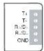

| PIN | RS-422/485 |
| 1 | T+ |
| 2 | T- |
| 3 | R+/D+ |
| 4 | R-/D- |
| 5 | GND |
RS-232 Pinouts
The female DB9 port for the RS-232 signal is shown in the following figure.

| PIN | RS-232 |
| 1 | DCD |
| 2 | TxD |
| 3 | RxD |
| 4 | DSR |
| 5 | GND |
| 6 | DTR |
| 7 | CTS |
| 8 | RTS |
Note: The RTS and CTS pins are shorted, and the DTR, DSR, and DCD pins are shorted, so that users do not need to worry about the hardware flow control cable wiring problem.
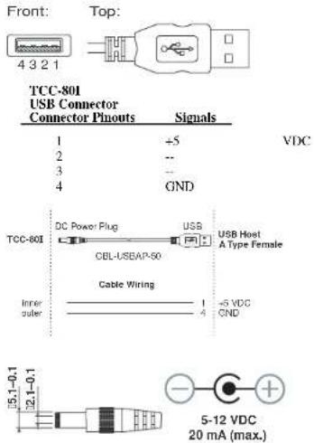
USB Power Cord
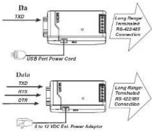
If additional external power is required, the TCC-80I can be connected to a standard 5 to 12 VDC power supply, or the USB power cord (CBL-USBAP-50) can be used.
USB "A" Male Connector
Isolated High-Speed Serial Port Powered Serial Media Conversion Solution
TCC-80I / TCC-80I-DB9
First high-speed, isolated, self-powered RS-232 to RS-422, 2-wire/4-wire RS-485 bi-directional converter with 2.5 KV isolation and 15 KV ESD protection.
Overview
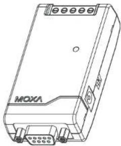
The TCC-80I is the world's first high-speed, isolated, self-powered converter. It is powered through the host's RS-232 port and provides complete signal conversion between RS-232 and RS-422/485 devices. The TCC-80I coverts back and forth between RS-232's TxD and RxD lines to either half duplex 2-wire RS-485 or the balanced signal of full duplex 4-wire RS-422/485. In addition, the TCC-80I provides comprehensive 15 KV LSD protection for all serial lines. Perhaps the most important feature is the 2.5 KV isolation designed to prevent ground loop currents, reduce damage caused by data loss, and prevent damage to the communication interfaces. The TCC-80I is also designed to provide RS-485 auto data direction control, in which the RS-485 driver is enabled automatically when the circuitry senses the TxD output from the RS-232 signal. Programming effort is not required to control the transmission direction of the half duplex RS-485 signal.
natural_image
Line drawing of a device labeled 'MOXA' with ports and connectors (no readable text beyond label)Package Checklist
• TCC-80I or TCC-80I-DB9
- USB Power Cord
- User's Manual
Applications
• Multipoint data acquisition
- Factory automation
- Remote serial device control
• Building security automation
• Critical industrial control
Features and Specifications
- Signals:
RS-232: TxD, RxD and GND
RS-422: TxD+(B)/-(A),
RxD + (B) / -(A), GND
RS-485: Data+(B)/-(A), GND
- Port types:
RS-232: Female DB9
RS-422/485: Terminal Block or Male DB9
• Auto-senses baudrates from 50bps to 921.6Kbps
• RS-232 loopback:
RTS to CTS: DTR to DSR and DCD
• Supports automatic RS-485 data direction control
with no baudrate switch settings
• 15 KV ESD for all serial RS-232/422/485 signals
• 2.5 KV isolation
• Built-in 120 ohm termination resistors for
RS-422/RS-485 (DIP switch selectable)
• Supports up to 32 units connected in an RS-485
multi-drop network
- Serial Power Source: TxD, RTS, or DTR
(RTS/DTR ON is recommended)
• LED Port Power Indicator (switch settings)
• External Power (jack): DC +5V to +12V adaptors
or USB Power cord (DC +5V)
• Operating temperature: 0 to 60°C
(32 to 140°F)
• Dimensions: 42 × 80 × 22 mm
- Case ABS + PC
• Weight: 50 ± 5 g
CE. FCC Class B approval
• Power Consumption: 20 mA at +5 VDC
(termination disabled)
- Warranty: 5 years
MOXA®
www.moxa.com
Moxa Inc.
TCC-80I/80I-DB9 User's Manual
P/N: 1802000801012
Third Edition.
Installation
Serial (RS-232) Port Power
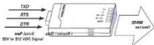
The RS-232 port of TCC-80I is designed with a female DB9 socket to connect directly to the host PC, with power drawn from the TxD. RTS, or DTR lines. TCC-80I is capable of taking enough power from the attached Tx line only. For those attached serial RS-232 devices which does not provide enough power on its Tx line, additional handshake lines should be connected to TCC-80I. The DC jack of TCC-80I is also provided for connecting a 5 to 12 VDC power supply via a USB power cord or external power adaptor.
Port Power Dissipation
When installing an RS-232 port-powered TCC-80I converter, pay attention to the power consumption, RS-232 cable length, power provided by the serial port, and the RS-422/485 transmission distance. In general, TCC-80I itself derives 70 mW from the power source; a standard COM port on a host PC can provide 70 to 90 mW of power if the TxD, RTS, and DTR lines are connected. Moreover, the RS-232 cable length should be shorter than 15 m (€ 9600 bps) to ensure that less power is lost from the host/device to the TCC-80L.
Serial Port Power Compatibility
Serial ports use a diversity of interface chips, but the power provided by the different ports is not always the same. In fact, some of the ports do not provide enough power to activate the TCC-80I. The on-board COM1 and COM2 ports seldom have problems. The table shows the add-on cards and the serial-to-Ethernet device servers that have been tested as a good power source to drive the TCC-80I.
| Multiport Serial Boards | Serial Device Servers |
| Moxa Boards | Moxa NPort Servers |
| CP-168U Series | CN2510 |
| CP-104U Series | CN2610 |
| CP-102U Series | NPort5110 |
| C168H Series | NPort5210 |
| C104II Series | NPort5410 |
| NPort5610 | |
| NPort6150 | |
| NPort6250 | |
| NPort6450 | |
| NPort6650 |
LED Port Power Indicator
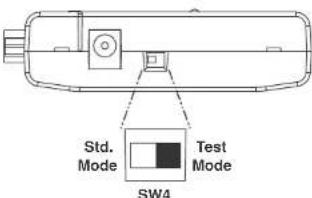
The best way to ensure the attached serial port provides enough electricity to the TCC-80I is to check the power indicator LED at the front panel. To do this, connect the TCC-80I to the target RS-232 port, and then turn the SW4 switch to the right side to the "Test" mode. The TCC-80I is receiving enough power if the LED lights up after activating the attached serial device. If the LED does NOT light up, you will need to attach the external power cord to the TCC-80I.
Note: Be sure to turn the SW4 switch back to Std. mode (the default) when you finish testing. When in Test mode, the TCC-80I WILL NOT transmit data.
Optional External Power
Termination is a critical requirement for port-power devices such as the TCC-80L. In most circumstances, termination resistors are used when the RS-422/485 cable length is longer than 100 m. Regardless of how much the data signal is dissipated, the termination resistors absorb more than 75 mW of
power from the power source when TCC-80I is unable to use the limited serial power. In other words, if long distance RS-422/485 transmission or termination is required, then an external USB power cord or DC power supply should be used (in this case, DIP SW3 must be ON).
flowchart
graph TD
    A["Input TXD"] --> B["USB Port Power Cord"]
    C["Input DTR"] --> D["Data"]
    B --> E["Long Range Terminated RS-422485 Connection"]
    D --> F["Long Range Terminated RS-622485 Connection"]
    G["5 to 12 VDC Ext. Power Adaptor"] --> H["Output"]
By testing the TCC-80I at different baudrates and transmission distances, we have determined the maximum transmission distance that can be achieved when using serial port power. The test results are shown in the following table.
| Baudrate (bps) | RS-422/485 Transmission Distance (m) | Embedded Terminator | External Power Required |
| 9600 | 1200 | (ON) 120Ω | NO |
| 19200 | 1200 | (ON) 120Ω | NO |
| 38400 | 600 | (ON) 120Ω | NO |
| 57600 | 300 | (ON) 120Ω | NO |
| 115200 | 150 | (ON) 120Ω | NO |
Switch and Jumper Settings
To change the operation mode, check the DIP Switch settings on the back panel.

DIP Switch Settings
| RS-422 with Terminator | SW1 | SW2 | SW3 |
| OFF | OFF | ON | |
| RS-422 | SW1 | SW2 | SW3 |
| OFF | OFF | OFF | |
| 4-wire RS-485 with Terminator | SW1 | SW2 | SW3 |
| ON | OFF | ON | |
| 4-wire RS-485 | SW1 | SW2 | SW3 |
| ON | OFF | OFF | |
| 2-wire RS-485 with Terminator | SW1 | SW2 | SW3 |
| ON | ON | ON | |
| 2-wire RS-485 | SW1 | SW2 | SW3 |
| ON | ON | OFF |
DIP SW1 and SW2 are used to select the operation modes (RS-422, 4W or 2W RS-485). The termination is controlled by DIP SW3.
Ext. Power supply
If additional external power is required, TCC-80I is designed to be connected to a standard 5 to 12 VDC power adapter.
- RS-232 Pinouts
- USB Power Cord
- USB "A" Male Connector
- Isolated High-Speed Serial Port Powered Serial Media Conversion Solution
- TCC-80I / TCC-80I-DB9
- Overview
- Package Checklist
- Applications
- Features and Specifications
- MOXA®
- Installation
- Serial (RS-232) Port Power
- Port Power Dissipation
- Serial Port Power Compatibility
- LED Port Power Indicator
- Optional External Power
- Switch and Jumper Settings
- Ext. Power supply
Brand : Moxa
Model : TCC-80I-RP
Category : Uncategorized