FGK-102 - Door/window sensor Fibaro - Free user manual and instructions
Find the device manual for free FGK-102 Fibaro in PDF.

User questions about FGK-102 Fibaro
0 question about this device. Answer the ones you know or ask your own.
Ask a new question about this device
Download the instructions for your Door/window sensor in PDF format for free! Find your manual FGK-102 - Fibaro and take your electronic device back in hand. On this page are published all the documents necessary for the use of your device. FGK-102 by Fibaro.
USER MANUAL FGK-102 Fibaro
OPERATING MANUAL
DOOR / WINDOW SENSOR
FGK - 101 - 107 v2.1 - v2.3
The Fibro Door, Viroanna Sensor is a wireless, rotary powered, 22-inch composite read sensor. Each time in the park is, the sensor's body and a magel sequence, a clock signal is sent in addition to the Vivron Door, Viroanna Sensor supports one OS10025 long-term sensor and has one colored line input. The Fibro Door, Window Sensor is a good tool for use with sound in home information systems, alarm and outside systems and everywhere are where information is limited to opening (closing of these windows, group prices, etc.) reached.
Technical data:
| Power supply | Single ER-4500 (10kA) 3.8V battery |
| Input | Single, peroxide, 100 |
| Supported temperature sensors | Single, DS40822 |
| Operating temperature | 0 - 10°C |
| Ratio protocol | 2x10^-6 |
| Ratio frequency | 40K 1 Hz/10040K 1 Hz/100K371.4 MHz/62.9Hz308.2 MHz/62.9 |
| Range | up to 80 m ohms, depending on building metering user and the building phone |
| Dimensions of 5×10^4 cm | 25 x 12 x 10 mm |
Technical information:
- Controlled via Fibro System components or any other Z-Wave comorbid controller.
- Door window opening detected through Sensor's body and a
• Quick installation - easily mounted or down, window, garage
grows, or let hinds, using double sided schemes we tape of razew
• Company's 2015-2016 temperature range: • After cooling DSS4830 use single unit, no longer than 30
• May be introduced in a north-southwest-bone. Natural

HINT
Connections should be made specifically according to the diagrams presented in this manual. Incorrect connections may be hazardous or lead to device damage.
I General Information on the Fibro System:
I become a system that then needs any uncontrolled transactions, it is bound on the 2/3/2006 technology, if there can a wide range of uncertainties in companies or other under-sampling. In quarters, manual-coated systems solution in direct, intervention between the reservoir and the manufacturer. Transient against an unsatisfied by access obstacle to such path for the manufactured oxy-fuel, furniture, etc. In the case, one the manual-sampling cameras for functions. The advantages of the F-bare system in the fact that the devices are not only as a signed receiver and manufacturer, but also as a signal repeater. If a direct link between the manufacturer and the receiver cannot be discontinued. The connection will be carried out with the use of other devices participating in community control.
F bar is a bidirectional wireless system. This means the digital is not only cent to its receivers, but also the receivers stand feedback confirming the reception of the digital. This also confirms the condition of receivers, which allows us to check whether or not a device has actually been written in order. The ability of the transmission of the Radio System is comparable with it who linked to the system. F bar covers in the free band for data transmission. The frequency depends on the radio regulation in each individual country.
Each Fiber network has to own unique network identification number home. By which is why one or more independent systems may be installed in a single building without any interference.
Although the Z-4Wave technology is fairly new. It has already been accepted as an official standard, just like 'WHF', numerous manufacturers from various fields offer solution based on Z-4Wave technology compatible with one another. This moves the system II for the future and a move for further development. For more information go to www.fiharm.com
I have published a dynamic network structure from the number of nodes-up, the location data of respective classes of the I have System is updated automatically, in our terms by confirming their relation to the making network.
II Sensor Installation:
- Connect Fibre Door/Window Sensor according to the
appropriate diagram (if necessary) - Placed battery inside the sensor's casing
- Includes into the 7-Wire system
- Install Fibro DoorWindow Sensor observing diagram 4.
2017年1月1日,公司召开2017年第二次临时股东大会。
EXPLANATION OF CONDUCTOR MARKINGS
TMP - Europe in Italy, Barcelona, Tel Aviv; 103-625
In a series table, to be an exchange of the two variables: 2/Alexes
IN - Potential in
TP - (TEMP POWER) - Power cut (or D816620 lat premiums
TD-/TEMP DATA! Signal kernel for OS18E20 temperature
SOTR20

NOTE:
To ensure the most accurate position detecting always installed the magnet in relation to the Sensor's body, as shown in diagram 4.

NOTE:
Fibro DoorWindow Sensor has two TMP buttons
inside and unders do the easing.
During normal operation both TMP buttons must be
secure. Do not use the sensor with closed easing.

NOTE:
TMP button, located on the underside of the device, has two functions:
1. set a mode into the next mode inside to i

Exclude from a 24-wave network, 2 warmer button. After certain installation (Fig. 5 and 6) running the whole sensor from location or opening for any may welcome the TMI' button and trigger an alarm. If the TMI' is required as a larger button, noation for next connection group must be registered optotrols, use the Transformer III
USING IN INPUT:
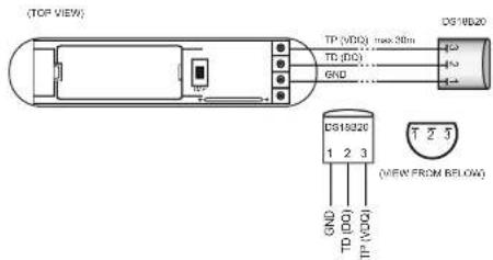
USING DG10B20 TEMPERATURE SENSOR:
ANTENNA ARRANGEMENT INSTRUCTIONS:
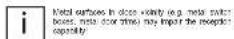
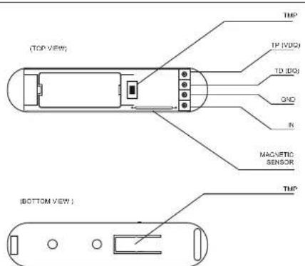
Diagram 1 - General
BELL-PUSH
Diagram 3 - Example connection - momentary switch
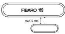
Diagram 4 - Correct positioning of the Sensor and the magnet
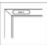
Diagram 5 - Correct sensor installation
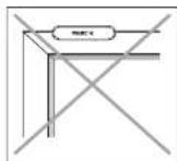
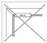
Diagram 6 - Incorrect sensor installation
GLOSSARY OF TERMS:
- INCLUSION - the Canadian sends out a Honda Info home, which makes it possible to add it to the Flare System (Home Center 2).
- EXCLUSION - remove the device from the F bare System.
- ASSOCIATION - controlling other devices included in the Fibro System,
- Multi Channel Association - controlling other multi-channel devices included in the Floor System
III Fibaro Sensor Start-up
1. Installation of the DoorWindow Sensor
STEP 1
Install the device observing the Figure 4 for correct positioning of the Sensor and the maps. Close the Sensor's casing.
[Inclusion/Exclusion] of the Picaro DownWindow Sensor [baffcn] the Z-Wave network.
8TEP 2
The Fibro module must be in range of the Hema Center 2 controller, because the procedure of inclusion to the Fibro System requires direct communication with the controller.
STEP 5
Loose TMP burden, which allows for proper inclusion of device.
STEP 4
Sel the Home Center 2 controller to the reduce on or work on more (see Home Center 2 controller including)
STEPS
The door door (Another Service is noted in the network by quickly proceeding. Pre TM 1 but not done from [the station is located on the outside of the device, needs to carry])
8TEP 6
Cerase, inclusion of the device to the network will be signalled by the Home Center 2 (see: Home Center 2 controller operation instructional
[Non-Text]
BATTERY USE
The Floor Down/Measure Sumner's battery is up 1-2 years, so defell softness.

Current battery level is displayed in the Home Center 2 configuration interface. It is a battery turns out, it means the battery needs replacement. In order not to trigger an alarm when replacing the battery, I and association group must be clicked and the Sensor's configuration must be arranged to default prior to the battery change.

NOTE
DoorWindow Button is equipped with a built-in LED. LED blinks each time DoorWindow Button changes its zone. LED blinking slowly = contact inclusion. LED blinking rapidly = inclusion ever.

NOTE
Every time any charges are needed to the manipulation of TP and TD lines (with) at where D816B20 sensor is connected. It is necessary to ensure the procedure of modulation and updated indicators of the sensor module to the 2' space network. The system will move into the learning mode only after connected D816B20 sensor has been detected (about 10 s).

NOTE
Do not, out and sends other than OS18E20 to the 1-sine line (TP and TD membrane).

NOTE
It is probriced to connect the TP and TD lines to devices not compatible with the 1-to-3e protocol.
2. Resetting the Fibro Door/Window Sensor
There is a very way to read the Fisram Data/Makes Service. The procedure draws its EFROM memory, including the main controller and Z-Wire network data.
To reset the Figure DoorWindow Sense please follow below instructions.
1) Tats off the Sensor's cover and remove battery. Make sure the TNP billion used.
2) Trust the Service is busy with a need,
S) Input (input value).
4) Remove the magnetic force on the Sensor's body.
6) Remove the battery
6) Re install the battery,
7) Reservill be confirmed by double LED link
[Non-Text]
NOTE
Resetting the device memory doesn't remove it from the Z-Wave network's main controller memory. To be able to re-clude the device into the Z-Wave network please conclude it first. Execution may be performed either before or after the reset procedure.
- Controlling the Fibro Door/Window Sensor with the Home Center 2 Controller
The DoorWindow Sensor is a multikannel device. This means that it is equipped with an independent input circuit and a 1-wire bus allowing it to be connected to a DB16820 temperature sensor. As a result, each device is represented by an independent icon in the System.
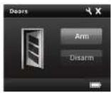
Fig. 1 - Door / Window Button room in the Home Center controller
Fig. 2 - OS18820 temperature sensor icon in the Home Center controller
Sensor does without a DS10820 sensor, or does with a water tank connected to (N) and will be recomposed by single door. After the DS10820 temperature sensor has lower tank connected, temperature sensor has will be discharged.

NOTE1
If a temperature sensor is on is not displayed, displace the fact the sensor itself has been connected, or if the temperature readings are incorrect, inspect the connection on the 1-wire bus, in particular the connection between sensor outputs and the line, and the total length of the bus wire which should not exceed 80 m.
IV Association
Association allows the Fibroic DoorWindow Sensor to directly control another device in the Z-wave network, e.g. Dimmer, Switch (On-Off). Roller Shutter or Trigger scene (scene control is only possible via the Home Center 2 controlled).

NOTE!
Association allows for direct transmission of control commands between devices and takes place without the partialation of the main controller. Owing to this mechanism the DocuWindow Sensor may common calls with devices even if the main controller is completely destroyed, e.g. in the event of a line.
The Fibra DoorWindow Sensor supports three association groups.
Group I is assigned to input NT [and the aggregate sensor]. Sending BASIC SET or ALARM external hardware.
Group II is assigned to TMP button. Once the button is released, ALARM GENERIC frame is sent to associated devices
Group III reports on the condition of the device, only one device may be assigned to the group (main controller by default).
The F-bare DoorWindow Sensor allows for control over 5 regular devices and 5 multichannel devices per group, out of which 1 field is reserved for the network controller.
In order to add an association (with the use of the Home Center 2
controller, go to device options by clicking this key:
Stand the place agents into the, specify which decisions and the associated, and to which container groups. Knowing of the manufacturer comments to associated decision might take up in a few hours depending on previous decision awards and the number of decisions within the market.

NOTE!
Any one, Association under given with any association commands are already being sent to devices, etc. but previous one.
V Configuration
The Door / Window Sensor offers a wide range of advanced settings. The parameters listed below are available in the Fibro configuration interface.
In order to examine the Date Center / Wireless Sensor (using the Date Center 2 controller) go on the device via a ordering pin

Hood, andet: The vitamin aspirate (a).
Device parameters:
Parameter no. 1
Input IN alarm cancellation delay. Additional delay after an alarm from input IN has ceased. The parameter allows user to specify additional time, after which the input IN alarm is cancelled once its bladder has ceased.
Default value: 0
Parameter value: 2 bps
Parameter no. 2
status change of the LED
Default rating
Available parameter set reps
B-1:11 Turned CF
表 10-2 号: 2017年6月
(1) 2018年1月1日
Parameter no. 3
Debut value = IRPL/T, NC (Karnal Close)
Aonish parvolester setings
0 - INPUT_M1 [NSFOOD LEQ] 1 - INPUT_ND [Harmot Com]
2 - INPUT MONGSTANLL
Percentile value: 1 [z=1]
Parameter no. 5
Type of control frame transmitted for association group 1, activated via IN input. The parameter allows you to specify the type of an element from or to know control frames that are assumed (BASIC: BET).
Default value: 255 BASIC SET
Available parameter settings
- A##N GENEER TURS
2 ALARMOD frame
\$ ALARM CO2 Fano
5.4 GEM WATER
255 - Control Time BASIC_SET
Parameter value: 1 byte.
Parameter no. 7
Value of the parameters specifying the based need of corresponding parameter order (which when 'should not' are needed) is used by the case from statistical groups?
In case of alarm from an alarm priority is spaced.
Debut value 255
Value of 256 makes it possible to activate a device. In case of the Dimmer module it means activating the device and setting it to the previously closed condition, e.g. when Dimmer is set to 92%, deactivated and then reorganized using 256 command. It will be automatically set to the previous condition in 92%.
Parameter value: 1 [byte]
Parameter no. 9
Deoachering transmission of the alarm canceling frame or the control frame deactivating the device (Basic) allows for disabling the function of deoachering the device and cancelling alarms for devices associated with IN input.
Default value: 0
Available personnel at long
The potential Canada company, information is
1 alarm isolation or school on commands for decrease, from association on groups are always used.
Parameter no. 12
Sensitivity to temperature changes the maximum acceptable reference between the last reported temperature and the current temperature need from the sense. If the temperature differ by the red value or more, it was used with the current temperature value is used in the sense recognized in secondary group in 3.
Denali value: 8 E,50C
Available parameter settings: 0 - 256.0x2 to "dsC" [23r] - 80.8x1
To the information obtained, we have to be in millions of dollars
Theorem 7.4. For Calculus
• delta T = 25.10, for Eplus
2.5 character value
delta - maximum acceptable temperature gradient in Celsius on Fahrenheit.
Up your next in
- If the above interval is set to 255 seconds the maximum required will be and according to the interval.
I'd be make up internal air to over 255 temperatures except will be sent each on 4 minutes.
Parameter value: 1 bps.
Parameter no. 13
Sending an alarm or control frame (for IN input, depending on parameter no.6 values), and TMP button alarm frame. The frame is sent in broadcast mode. I.e. to all devices within range information sent in this mode is not repeated by the mesh network.
Default value: 0
available parameter settings
D-N and KP-Emycled mode irradiance
-
14 broadest 100, 27A, 15 broadest 100, 31C;
-
N and "NE" broadcast post date
Parameter value: 1 byte.

Рараметр No. 14
The decision class is the possibility of sending commands compatible with Command class, where adoption. Information is sent in device assigned to association group on 3
Entirements such as the Entire Center 2 were able to explore such certificate and note on those certificates actually covered, in which specific street Els have been recognized. The user may require the functionality of a hidden connected to the input by the following: the sequence of it is being planted. The example, though they would trigger the passage? Soone and into stock would trigger the missing season. To fully use the approximate skill by the parameter n=54. It is recommended to be used in secondary or allergic switch (pananarian n=3).
Score 10 is determined in the following manner.
Birpur.
SALON FROM "BRIC" OF DUC
Remaining IDs are recognized correctly if the value of parameter
in S was all in 2
E-mail: 012
Douche de 12:14
To: 46:1015
Fermester, 1 l.u.
