
500SS - Car radio KICKER - Free user manual and instructions
Find the device manual for free 500SS KICKER in PDF.


| Type | Car audio amplifier (2-channel stereo) |
| Brand | KICKER |
| Model | 500SS |
| Power Output (RMS) per channel into 4Ω | 250W (0.02% THD, 20Hz-20kHz) |
| Power Output (RMS) per channel into 2Ω | 425W (0.02% THD, 20Hz-20kHz) |
| Bridged Power (RMS) into 4Ω | 850W (0.02% THD, 20Hz-20kHz) |
| Frequency Response | 10 Hz – 28 kHz (+0, -1dB) |
| Signal-to-Noise Ratio | >100 dB (unweighted, relative to rated power) |
| Input Sensitivity | 125 mV – 2.5 V |
| Slew Rate | 36 V/μs |
| Damping Factor | >350 @4Ω |
| Input Impedance | 22 kΩ |
| Max Current Draw | 130 A |
| Supply Voltage | 12.5 – 16 VDC (negative ground) |
| Protection Circuits | Thermal, speaker short, reversed power connections |
| Optional Modules | ASW, AMR, ATW, AEE, AEQ, ACR, ARG |
| Wiring Gauge Required | 8 AWG for power and ground |
| Fuse Rating (at battery) | 120 A (within 18 inches of battery) |
| Mounting Orientation | Vertical or flat with fins up |
| Mounting Surface | Non-conductive |
| Warranty | 3 years if installed by authorized dealer, otherwise 1 year |
Frequently Asked Questions - 500SS KICKER
User questions about 500SS KICKER
0 question about this device. Answer the ones you know or ask your own.
Ask a new question about this device
Download the instructions for your Car radio in PDF format for free! Find your manual 500SS - KICKER and take your electronic device back in hand. On this page are published all the documents necessary for the use of your device. 500SS by KICKER.
USER MANUAL 500SS KICKER
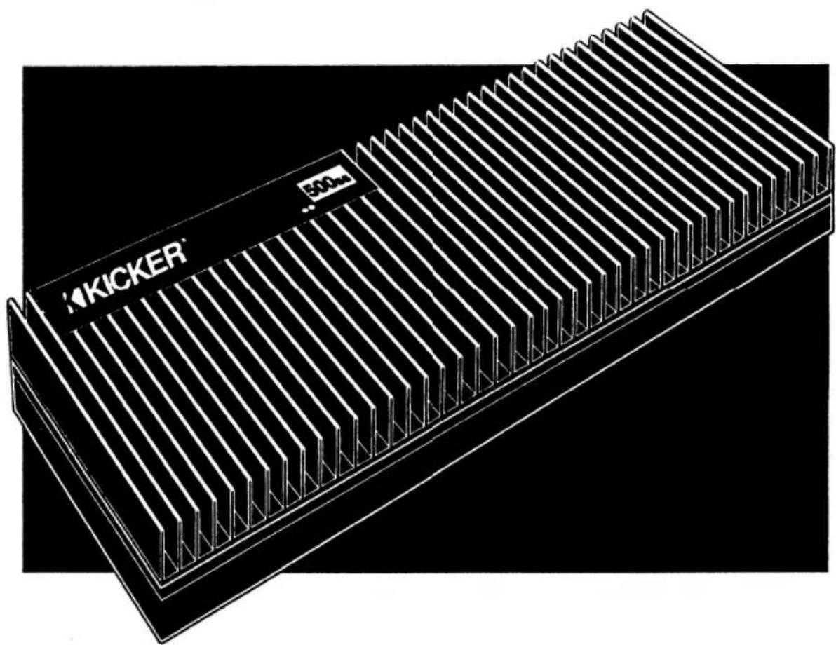
Congratulations. You've just purchased the best amplifier in car audio. It's only natural that an amplifier this good would be called a KICKER. Over the last decade Stillwater Designs has established KICKER as the premier car audio speaker. The name is synonymous with rugged design, outstanding performance, and timeless quality, a KICKER tradition that is continued in your new amplifier.
natural_image
Technical line drawing of a Kicker memory chip with visible slots and control panel (no text or symbols beyond branding)CONTENTS:
Introduction.... 2 Setting Gain Control .... 8
Features.... 2 Modules.... 9
Wiring 3 Trouble Shooting 9
Mounting 4 Specifications 11
System Diagrams .... 6 Warranty.... 12
INTRODUCTION
From the cast aluminum base to the completely functional heat sink, this amp is built for performance. Uncompromising attention to detail, flexibility and pure clean power, KICKER Car Audio Amplifiers—The way amplifiers ought to be.
Stillwater Designs recommends that the KICKER Amplifier be installed at an authorized dealer. The length of your KICKER Amplifier's warranty is three times as long when installed by an authorized KICKER Dealer.
FEATURES & CONTROLS
Your new KICKER Power Amplifier incorporates today's most advanced and innovative design techniques. Three different circuits provide continuous protection from the severe conditions associated with car audio. These are thermal, speaker short, and reversed power connections. The high input impedance allows for multiple amplifiers to be daisy-chained from a single source, without degrading the signal. The custom tooled connectors provide positive contact for power and speaker connections, while allowing maximum gauge wires to be used effectively. Optional plug-in modules can provide active equalization, crossover, and other signal processing functions. The output of the module can be directed to successive amplifiers through the signal output of the initial amplifier. All these features are included in an attractive and easy to install chassis.
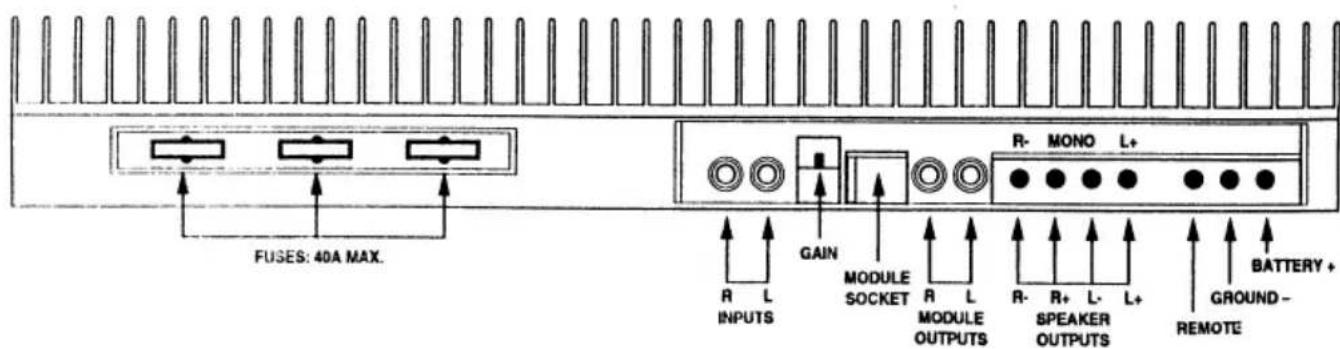
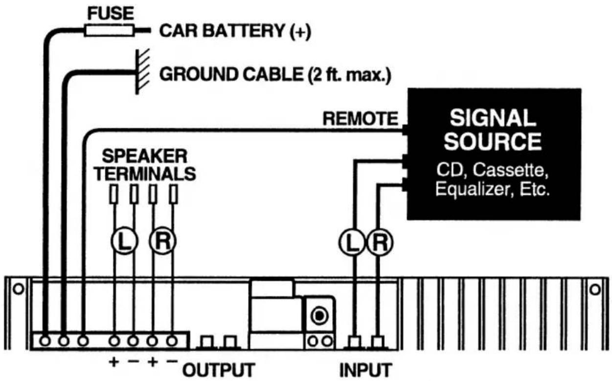
The 500ss amplifier requires 8 gauge power wires for both +12v and ground connections. The screws in the amplifiers terminal strip must be very tight. Always make the ground connection first when installing this amplifier and disconnect ground last when removing it from the system. Connect the ground wire, which is 24 inches or less, to a structural chassis member. Be sure this connection is to bare metal and securely screwed or bolted. (It is not recommended to run the ground wire to the battery.) Run the positive wire directly to the positive terminal of the battery and use a 120 amp fuse within 18 inches of the battery. This fuse protects the wire run from the battery. Run the power and signal wires on opposite sides of the car. This helps to reduce noise in the signal wires between the source and the amplifier. The speaker connections can accept up to 8 gauge wire to reduce losses in long runs.
The cover panel allows for two wiring methods; standard and stealth. The standard method requires the removal of a break-away panel, as shown in the following diagram.
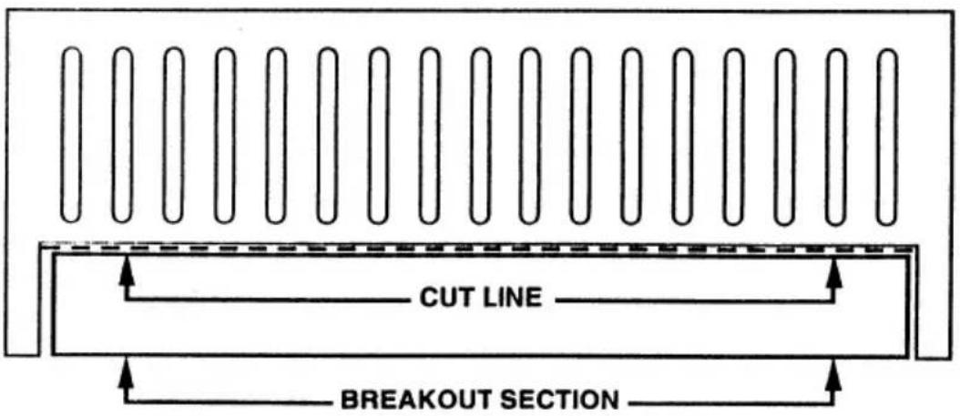
The breakout panel is removed by scoring the groove with a razor knife and bending the shaded portion away from the cut. The remaining edge can then be touched up with a small file. This allows the wiring to be run directly out of the control panel side of the amplifier.
The opening in the base of the amplifier allows the wiring to travel through the base without altering the cover panel for a stealth look, which is often preferred for custom installations. With this method, short right angle RCA connectors are required for the signal connections.
Caution:
Do not route the wires beneath the vehicle without proper protection. Do not pinch wires beneath seat frames or trim panels.
Caution:
Do not ground speaker leads.
MOUNTING INSTRUCTIONS
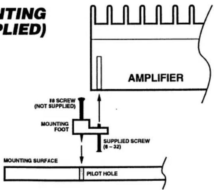
The orientation of the amplifier is critical to provide proper cooling. The cooling fins are designed to operate best when run in a vertical position or mounted flat with the fins up. The mounting feet can be attached so they are positioned to the end or the edge of the amplifier, whichever works best for you.
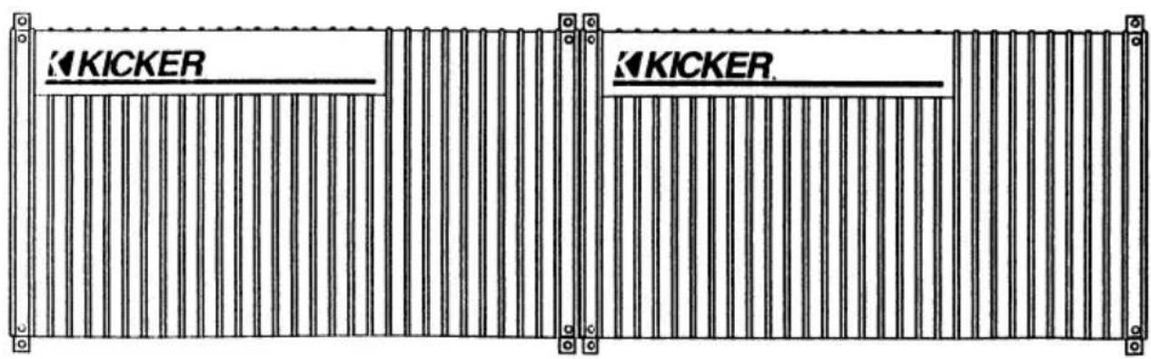
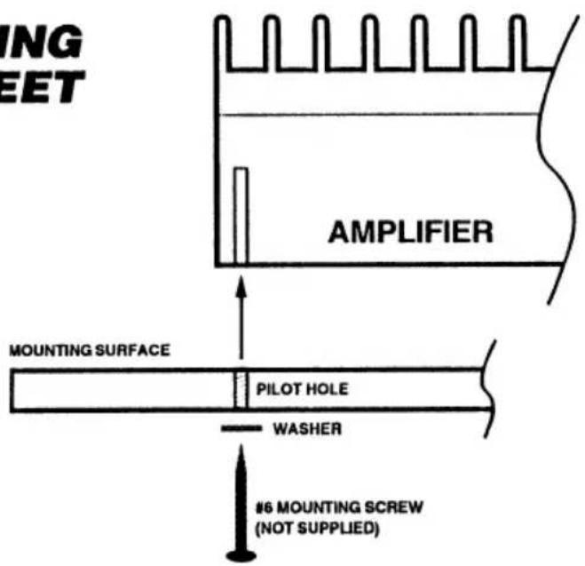
Stealth mounting is accomplished by using the template provided in the box. The template shows where the screw holes are located and where the mounting surface must be cut out to run the wires. A #6 sheet metal screw must be used when stealth mounting the amplifier. The chart on the template shows the screw length needed for the thickness of mounting board used.
Since the case of the amplifier is part of the noise shielding system in the amplifier, it is necessary to mount it to a non-conductive surface. Mounting the amplifier to chassis ground will cause engine noise.
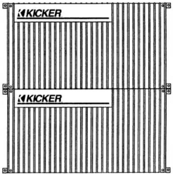
AMPLIFIER MOUNTING
WITHOUT FEET
AMPLIFIER MOUNTING WITH FEET (SUPPLIED)
SYSTEM DIAGRAMS
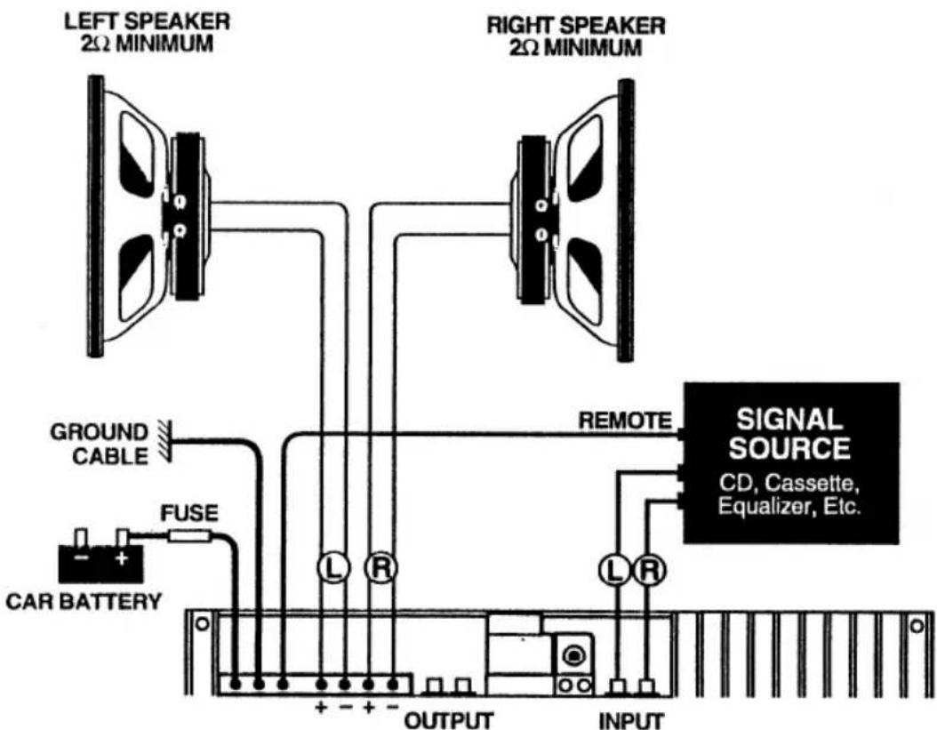
Two Channel Operation
In conventional stereo or two channel operation, a signal input is required for each channel and a speaker load of no less than 2 ohm is connected to the right and left outputs.
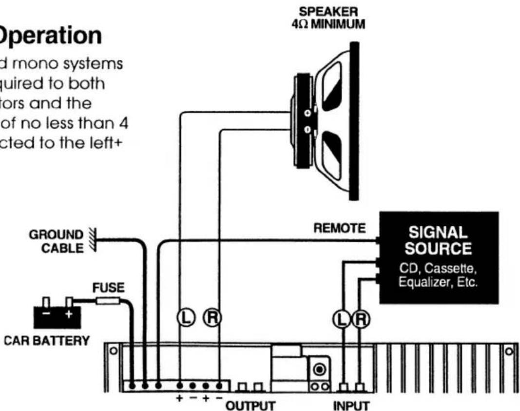
Bridged Operation
For bridged mono systems an input is required to both input connectors and the speaker load of no less than 4 ohm is connected to the left+ and right-.
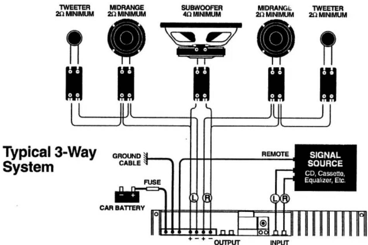
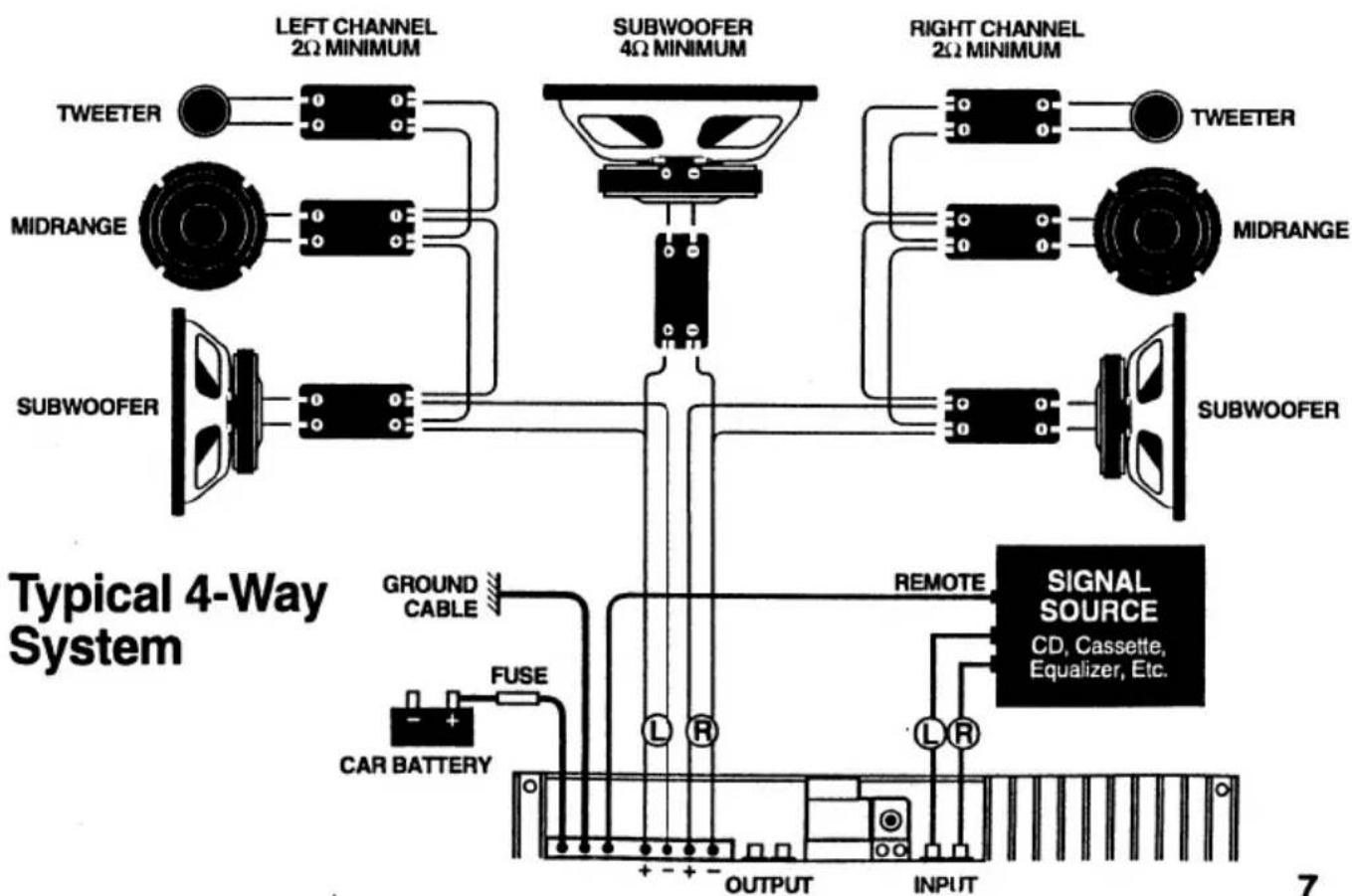
Three Channel (Mixed Mono) Operation
(Left Channel, Right Channel & Subwoofer Channel)
The upper frequency drivers are connected in stereo while the mono woofer is connected from the left+ to the right-. A typical crossover point would be 100 Hz. These systems require the use of passive crossovers to maintain proper impedance loads at all frequencies.
flowchart
graph TD
    A["TWEETER"] --> B["LEFT CHANNEL 2Ω MINIMUM"]
    C["MIDRANGE"] --> D["SUBWOOFER"]
    E["CAR BATTERY"] --> F["FUSE"]
    G["SUBWOOFER"] --> H["Ground CABLE"]
    I["SUBWOOFER"] --> J["OUTPUT"]
    K["RIGHT CHANNEL 2Ω MINIMUM"] --> L["SUBWOOFER"]
    M["TWEETER"] --> N["MIDRANGE"]
    O["SUBWOOFER"] --> P["OUTPUT"]
    Q["SIGNAL SOURCE"] --> R["CD, Cassette, Equalizer, Etc."]
    S["REMOTE"] --> T["OUTPUT"]
    U["INPUT"] --> V["OUTPUT"]
DAISY CHAINING AMPLIFIERS
When operating more than one amplifier in the same frequency range it is possible to connect the input of the next amplifier to the output of the first. Daisy chaining requires only one source for several amplifiers.
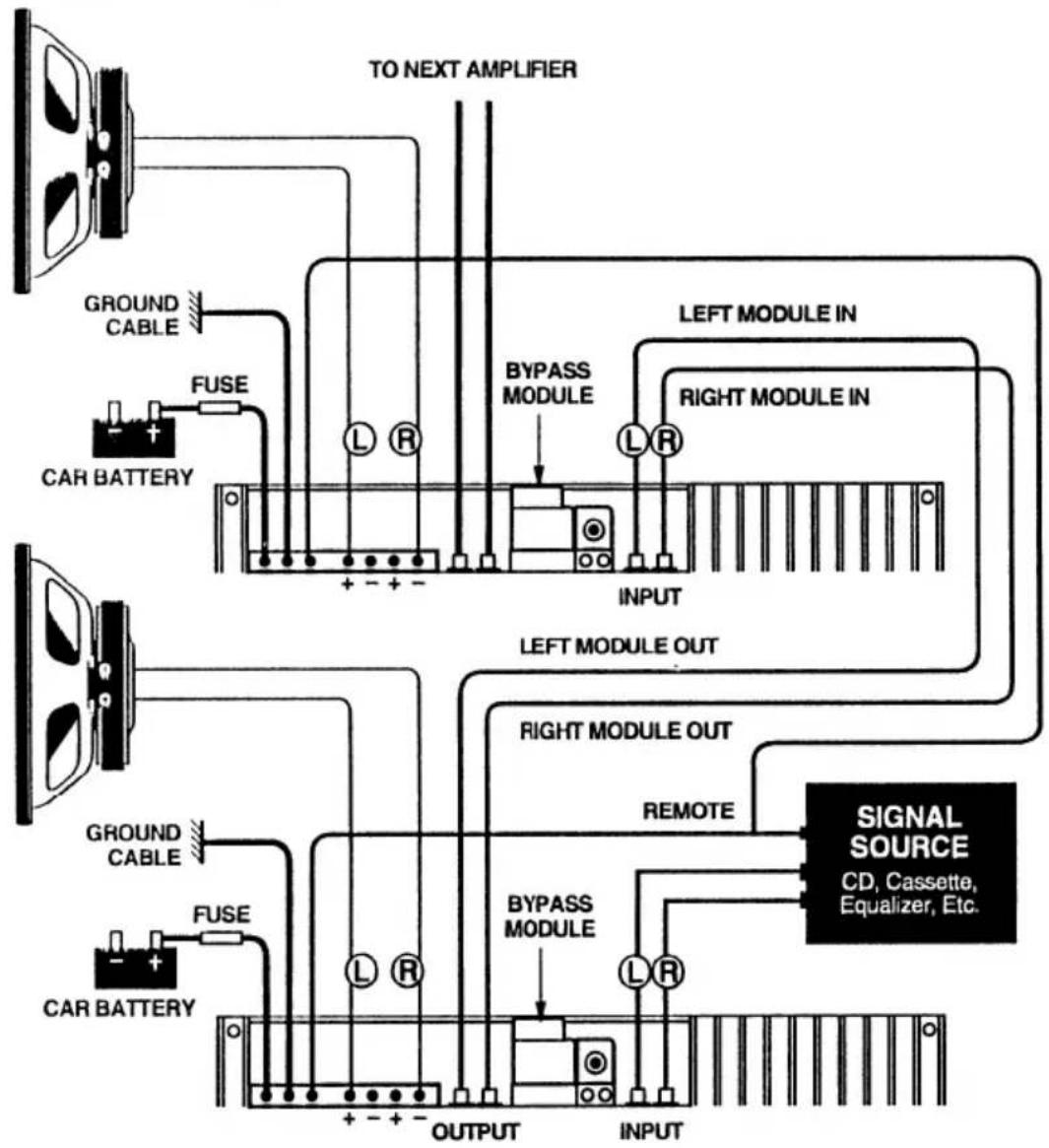
flowchart
graph TD
    A["CAR BATTERY"] --> B["FUSE"]
    B --> C["Ground Cable"]
    C --> D["TO NEXT AMPLIFIER"]
    D --> E["LEFT MODULE IN"]
    E --> F["BYPASS MODULE"]
    F --> G["INPUT"]
    G --> H["RIGHT MODULE IN"]
    H --> I["LEFT MODULE OUT"]
    I --> J["BYPASS MODULE"]
    J --> K["OUTPUT"]
    K --> L["INPUT"]
    L --> M["SIGNAL SOURCE"]
    M --> N["CD, Cassette, Equalizer, Etc."]
    style A fill:#f9f,stroke:#333
    style L fill:#ccf,stroke:#333
    style M fill:#cfc,stroke:#333
SETTING GAIN CONTROL
The gain control is provided for level matching purposes. It DOES NOT give the amplifier any more power by turning it up. Its purpose is to adjust the sensitivity of the amplifier in relation to the output level provided by the source.
Start with the amp gain set to minimum by turning the control counterclockwise. Turn the source level up until distortion is barely audible. Then turn it down slightly. This will typically be at about 75% to 85% of full volume. Raise the amplifier gain until distortion is just audible. The gain is now set correctly. Check the level with cd/tape and tuner to make sure the adjustment is correct for all sources.
OPTIONAL MODULES
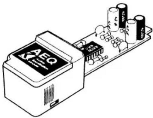
All KICKER amplifiers have a Module Docking Port, which allows the use of any KICKER Module. These modules greatly increase your amplifier's versatility, and cost very little when compared to "stand alone" units with the same functions. When not using a KICKER Module, the Bypass Module supplied with your amp must be left in place.
Active Crossover Modules:
These 2-way modules allow you to use separate amplifiers for your subwoofers, midbass drivers, midranges, or tweeters. By doing this, especially on the subwoofer, a clean and undistorted sound is available at much higher listening levels.
Each module offers a range of selectable crossover frequencies and 24dB/octave filtering.
natural_image
Illustration of an electronic circuit board with integrated components and capacitors (no text or symbols)- ASW - 60Hz, 80Hz, or 100Hz subwoofer/midbass or midrange crossover.
• AMR - 175Hz, 250Hz, or 350Hz midbass/midrange crossover. - ATW - 3500Hz or 4500Hz midrange/tweeter crossover.
Specialty Modules::
- AEE (Active Electronic Enclosure) – When used with KICKER Freeair™ woofers, this module simulates the response of KICKER Competition™ woofers in a sealed enclosure.
- AEQ (Active EQ) – Frequency Enhancement and extension module that specializes frequencies in the low bass region as well as the upper treble regions.
- ACR (Active Center/Rear Fill) – This module allows one amplifier to drive a center channel and rear speakers independently at the same time.
- ARG (Active Remote Gain) – An ideal amplifier enhancement module that provides a remote gain control function.
Consult with your authorized KICKER dealer for more information.
TROUBLE SHOOTING

Power indicator off, no output.
With a Volt Ohm Meter (VOM),
- Check +12V power terminal.
- Check GND terminal.
- Check remote turn-on terminal.

Power indicator on, no output.
- Check RCA and speaker connections.
- Test speaker outputs with known good test speaker.
- With VOM in AC volts position, check RCA for input voltage.

No output from one channel.
- Check RCA and speaker connections on that channel.
- Swap RCA connections between channels.
- Swap speaker connections between channels.

Yellow LED protection light is on and there is no output.
Case 1: Amp is very hot.
Thermal protection is engaged. Verify that speaker load impedance is not below specified minimums. Check area surrounding amplifier for objects which may restrict air flow and proper cooling. If this continues to be a problem, take vehicle to an authorized KICKER dealer for evaluation.
Case 2: Output resumes momentarily when system is turned off and then back on.
Short circuit protection is engaged. Verify that speaker load impedance is not below specified minimums. With VOM check for short between speaker positive and negative, and between speakers and chassis ground. If unable to perform task or locate problem, take vehicle to an authorized KICKER dealer for evaluation.

Alternator noise (a whining that varies with engine RPM.)
Make sure source grounds are as short as possible and connected to bare chassis metal, not to factory radio ground. Beware of dash braces. Many are not grounded to chassis. Check RCA cable for proper connections and routing. Try another cable routed in a different location in the vehicle. If unable to cure problem, take vehicle to an authorized KICKER dealer for evaluation. Do not ground amp chassis.

Stereo image is unfocused and bass is reduced.
Check system phasing by turning the balance control to the left and right speakers. If bass is more prominent when turned to either side, check speaker wiring for proper positive and negative connections. Reverse connections on one speaker if necessary.
Caution:
When jump starting the vehicle, be sure that connections made with jumper cables are correct. If improper connections are made, it can result in blown fuses in the amplifier power line as well as other systems in the vehicle.
SPECIFICATIONS
| Number of channels | 2 (Stereo) |
| Rated power/channel Into 4Ω, no more than 0.02% THD, 20Hz to 20KHz, both channels driven 12.5-16VDC | 250W |
| Rated power/channel Into 2Ω, no more than 0.02% THD, 20Hz to 20KHz, both channels driven 12.5-16VDC | 425W |
| Bridged power Into 4Ω, no more than 0.02% THD, 20Hz to 20KHZ, both channels driven, 12.5-16VDC | 850W |
| Max Current Draw, 2Ω stereo load or 4Ω bridged load | 130A |
| Frequency Response, (+0, -1dB) | 10 Hz to 28 kHz |
| Signal to Noise Ratio, unweighted, relative to rated power/channel | >100 dB |
| Input Impedance | 22 kΩ |
| Input Sensitivity range | 125mV – 2.5V |
| Slew Rate | 36Vμs |
| Damping Factor, @4Ω | >350 |
LIMITED WARRANTY
Stillwater Designs warrants this product to be free from defects in material and workmanship under normal use for a period of three (3) years from date of original purchase when installed by an Authorized KICKER Dealer or one (1) year from date of original purchase if not installed by an Authorized KICKER Dealer. If this product is labeled "B Stock", it is warranted for one (1) year from date of purchase, regardless of place of installation. Should service be necessary under this warranty for any reason due to manufacturing defect or malfunction during the warranty period, Stillwater Designs will replace or repair (at its discretion) the defective merchandise at no charge.
This warranty is valid only for the original purchaser and is not extended to owners of the product subsequent to the original purchaser. Any applicable implied warranties are limited in duration to a period of the express warranty as provided herein beginning with the date of the original purchase at retail, and no warranties, whether express or implied, shall apply to this product thereafter. Some states do not allow limitations on implied warranties, therefore these exclusions may not apply to you.
This warranty gives you specific legal rights; however you may have other rights that vary from state to state.
WHAT TO DO IF YOU NEED WARRANTY OR SERVICE
If it becomes necessary for you to send defective merchandise, package all defective items in the original container or in a package that will prevent shipping damage, and return to Stillwater Designs, 5021 North Perkins Road, Stillwater, OK 74075
Return only defective components. Non-defective items received will be returned freight collect.
Include a dated proof-of-purchase from an Authorized Dealer. Warranty expiration on items returned without proof-of-purchase will be determined from the manufacturing date code. Coverage may be invalidated if this date is greater than one (1) year previous to the date item is sent in. Freight must be prepaid; items received freight collect will be refused.
Failure to follow these steps may void your warranty. Any questions can be directed to the Warranty Department at (405)624-8510.
WHAT IS NOT COVERED?
This warranty is valid only if the product is used for the purpose for which it was designed. It does not cover:
- Products purchased from an unauthorized dealer.
• Damage due to improper installation - Damage caused by exposure to water, excessive heat, chemical cleaners, and/or UV radiation.
- Damage through negligence, misuse, accident or abuse. Repeated returns for the same damage may be considered abuse.
- Freight damage.
-
The cost of shipping product to Stillwater Designs Service.
-
Items previously repaired or modified by any unauthorized repair facility.
- Items returned from unauthorized individuals or dealers.
- Return shipping on non-defective items.
- Products with tampered or missing barcode labels.
HOW LONG WILL IT TAKE?
Stillwater Designs maintains a goal of 24-hour service for all returns. Delays may be Incurred if lack of replacement inventory or parts is encountered.
INTERNATIONAL WARRANTY
Contact your International Stillwater Designs dealer or distributor concerning specific procedures for your country's warranty policies.
P.O. Box 459 • Stillwater, Oklahoma 74076 • U.S.A. • 405 624-8510
STILLWATER Design ^®

KICKER components are capable of producing sound levels that can permanently damage your hearing! Turning up a system to a level that has audible distortion is more damaging to your ears than listening to an undistorted system at the same volume level. The threshold of pain is always an indicator that the sound level is too loud and may permanently damage your hearing. Please use common sense when controlling volume!
- CONTENTS:
- INTRODUCTION
- FEATURES & CONTROLS
- Caution:
- MOUNTING INSTRUCTIONS
- SYSTEM DIAGRAMS
- Two Channel Operation
- Bridged Operation
- Three Channel (Mixed Mono) Operation
- (Left Channel, Right Channel & Subwoofer Channel)
- DAISY CHAINING AMPLIFIERS
- SETTING GAIN CONTROL
- OPTIONAL MODULES
- Active Crossover Modules:
- Specialty Modules::
- TROUBLE SHOOTING
- Power indicator off, no output.
- With a Volt Ohm Meter (VOM),
- Power indicator on, no output.
- No output from one channel.
- Yellow LED protection light is on and there is no output.
- Case 1: Amp is very hot.
- Case 2: Output resumes momentarily when system is turned off and then back on.
- Alternator noise (a whining that varies with engine RPM.)
- Stereo image is unfocused and bass is reduced.
- LIMITED WARRANTY
- WHAT TO DO IF YOU NEED WARRANTY OR SERVICE
- WHAT IS NOT COVERED?
- HOW LONG WILL IT TAKE?
- INTERNATIONAL WARRANTY
Brand : KICKER
Model : 500SS
Category : Car radio