
FR2 - NAS AJA - Free user manual and instructions
Find the device manual for free FR2 AJA in PDF.

| Product Type | Multiple Card Frame (Video Processing) |
| Model | FR2 (also FR2-D with redundant power) |
| Dimensions | 19" W x 3.5" H x 13" D (2 RU) |
| Weight | Approx. 12 lbs (5.4 kg) |
| Power Supply | 100 Watt capacity, universal input 90-240 VAC, hot-swappable |
| Redundant Power | Optional, diode-isolated; FR2-D includes two supplies |
| Cooling | 3-fan forced-air inside removable front door |
| Module Slots | 10 (cells) |
| I/O per Slot | 9 BNC connectors |
| Reference Input | 1 BNC (frame reference) |
| Reference Distribution | Active distribution amplifier to all slots |
| Remote Monitoring | RJ45 port for power supply voltage monitoring |
| Power LEDs | PS1 and PS2 on front panel for each supply |
| Compatibility | Leitch 6800-series video cards |
| Front Door | Removable (heavy, no hinge) |
| Power Supply Replacement | Hot-swappable from front (after removing rear screw) |
| Safety Compliance | FCC Class A, CE, ICES-003, UL/CSA, VCCI |
| Warranty | 5 years from purchase date |
| Operating Temperature | 0°C to 40°C (32°F to 104°F) |
| Storage Temperature | -20°C to 70°C (-4°F to 158°F) |
Frequently Asked Questions - FR2 AJA
User questions about FR2 AJA
0 question about this device. Answer the ones you know or ask your own.
Ask a new question about this device
Download the instructions for your NAS in PDF format for free! Find your manual FR2 - AJA and take your electronic device back in hand. On this page are published all the documents necessary for the use of your device. FR2 by AJA.
USER MANUAL FR2 AJA
(Models FR1, FR1-D, FR2 and FR2-D)
Published: 7/13/10
Installation and Operation Guide
Because it matters.

Trademarks
AJA, Io, and Kona are trademarks of AJA Video, Inc. All other trademarks are the property of their respective holders.
Notice
Copyright © 2010 AJA Video, Inc. All rights reserved. All information in this manual is subject to change without notice. No part of the document may be reproduced or transmitted in any form, or by any means, electronic or mechanical, including photocopying or recording, without the express written permission of AJA Inc.
Contacting Support
To contact AJA Video for sales or support, use any of the following methods:
180 Litton Drive, Grass Valley, CA. 95945 USA
Telephone: +1.800.251.4224 or +1.530.274.2048
Fax: +1.530.274.9442
Web: http://www.aja.com
Support Email: support@aja.com
Sales Email: sales@aja.com
When calling for support, have all information on the product (serial number etc.) at hand prior to calling.
Limited Warranty
AJA Video warrants that this product will be free from defects in materials and workmanship for a period of five years from the date of purchase. If a product proves to be defective during this warranty period, AJA Video, at its option, will either repair the defective product without charge for parts and labor, or will provide a replacement in exchange for the defective product.
In order to obtain service under this warranty, you the Customer, must notify AJA Video of the defect before the expiration of the warranty period and make suitable arrangements for the performance of service. The Customer shall be responsible for packaging and shipping the defective product to a designated service center nominated by AJA Video, with shipping charges prepaid. AJA Video shall pay for the return of the product to the Customer if the shipment is to a location within the country in which the AJA Video service center is located. Customer shall be responsible for paying all shipping charges, insurance, duties, taxes, and any other charges for products returned to any other locations.
This warranty shall not apply to any defect, failure or damage caused by improper use or improper or inadequate maintenance and care. AJA Video shall not be obligated to furnish service under this warranty a) to repair damage resulting from attempts by personnel other than AJA Video representatives to install, repair or service the product, b) to repair damage resulting from improper use or connection to incompatible equipment, c) to repair any damage or malfunction caused by the use of non-AJA Video parts or supplies, or d) to service a product that has been modified or integrated with other products when the effect of such a modification or integration increases the time or difficulty of servicing the product.
THIS WARRANTY IS GIVEN BY AJA VIDEO IN LIEU OF ANY OTHER WARRANTIES, EXPRESS OR IMPLIED. AJA VIDEO AND ITS VENDORS DISCLAIM ANY IMPLIED WARRANTIES OF MERCHANTABILITY OR FITNESS FOR A PARTICULAR PURPOSE. AJA VIDEO'S RESPONSIBILITY TO REPAIR OR REPLACE DEFECTIVE PRODUCTS IS THE WHOLE AND EXCLUSIVE REMEDY PROVIDED TO THE CUSTOMER FOR ANY INDIRECT, SPECIAL, INCIDENTAL OR CONSEQUENTIAL DAMAGES IRRESPECTIVE OF WHETHER AJA VIDEO OR THE VENDOR HAS ADVANCE NOTICE OF THE POSSIBILITY OF SUCH DAMAGES.
Important Safety Information
See the Safety & Regulatory information in Appendix A at the back of this manual.
Introduction
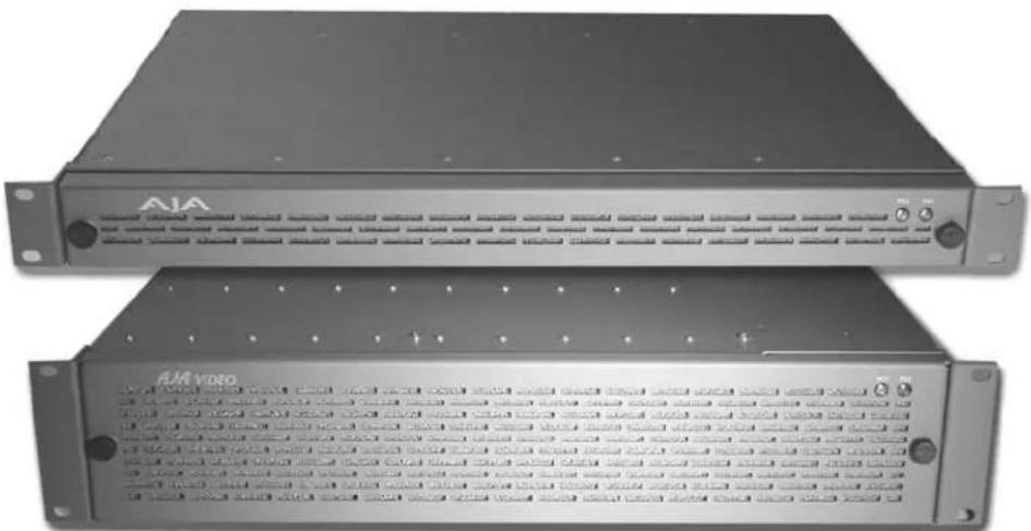
The AJA FR1 and FR2 are multiple-card frames that support both AJA's R-series video card modules and other industry standard modules. They bring high-density packaging, high capacity power supplies, and forced fan cooling to your rack—so you don't need to reserve space above or below the frames.
Model FR1
The FR1 frame offers space for four modules in a 1-RU space. AJA's own R5 and R20 modules fit into the frame, as well as industry standard modules. Color black reference can be connected at a rear panel BNC for distribution passively to all frame modules.
Model FR2
The FR2 frame provides greater space, housing up to ten modules in a 2-RU space. Like the FR1, the FR2 supports both AJA's own R-series modules as well as industry standard modules. Color black reference in the FR2 is also distributed to all modules, but it's actively distributed rather than passively. Optional redundant power supplies are available for the FR2 frame, and all power supplies are easily hot-swapped from the front of the unit (one screw on the rear panel must be removed on each power supply prior to removal).
Features
The FR1 and FR2 frames offer a variety of unique features for easy connectivity and ease of installation in any environment.
natural_image
Two black electronic equipment units labeled 'AVA' and 'AIA video', showing front panels and control knobs (no readable text beyond labels)FR1 and FR2 Frames
FR1 Features
• Dual fan forced-air cooling
- Optional redundant power supply, diode isolated
• Universal power supply is auto-ranging from 90 to 240 VAC with 50 Watts capacity
• 4 module slots (cells)
• Each module cell is provided with 9 BNC inputs or outputs
- Single frame reference BNC distributes passively to all cells
- Remote power supply monitoring via RJ45 port on rear panel
• Power LEDs on front panel show power status
- Compatible with common industry frames—video cards only (Leitch™ 6800-series)
FR2 Features
- Triple fan forced-air cooling inside removable access door
• Hot-swappable power supplies - Optional redundant power supplies, diode isolated
• Universal power supply is auto-ranging from 90 to 240 VAC with 100 Watts capacity
• 10 module slots (cells)
• Each module cell is provided with 9 BNC inputs or outputs - Single frame reference BNC distributes actively to all cells via an internal distribution amplifier
- Remote power supply monitoring via RJ45 port on rear panel
• Power LEDs on front panel show power status - Compatible with common industry frames—video cards only (Leitch™ 6800-series)
I/O Connections
FR1 Multiple Card Frame, Rear Panel Connectors

flowchart
graph TD
    A["Power Supply Sockets For Line Cords"] --> B["Frame Reference"]
    B --> C["RJ45 Cell 10 J91 to J99"]
    B --> D["Power Supply Relief Screws (must remove to replace supply)"]
    C --> E["Cell 1 J1 to J9"]
    D --> F["Cell 2 J11 to J19"]
    style A fill:#f9f,stroke:#333
    style B fill:#ccf,stroke:#333
    style C fill:#cfc,stroke:#333
    style D fill:#fcc,stroke:#333
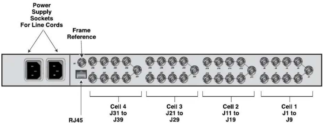
FR2 Multiple Card Frame, Rear Panel Connectors
Input/Output BNCs (groups of 9 per cell)—Each unique slot in the FR1/FR2 frames connect to a group of 9 BNCs on the frame rear panel. The actual function of the BNC connectors is dependent on the video card installed. Each group of 9 BNCs corresponds to the card installed in the same position; for example the right-most card connects to the right-most group of connectors at the position on the rear panel.
Frame Reference BNC—Both the FR1 and FR2 frames have this frame reference input BNC connector, which feeds an external reference video signal to all modules installed in the frame. How the signal is distributed differs for the FR1 and FR2 frames. Additionally, individual modules can usually be strapped as to whether external reference is distributed from the frame or directly to BNCs on the module's corresponding cell group (the 9 BNCs on the rear panel). See the "Note" below for more information on looping reference inputs in the cell group.
FR1 Frame: the external reference signal is distributed passively to all frame modules. Cards installed in the frame should have "FRAME" reference selected, and one and only one card in the frame should have "TERMINATION" set to "ON." All other cards in the frame should have TERMINATION set to "OFF."
FR2 Frame: the external reference signal is distributed by an in-frame distribution amplifier to all frame modules. This system terminates the Frame Reference input BNC and buffers the signal to all slots. Cards installed in the FR2 frame should have "FRAME" set for reference select, and all cards should have TERMINATION set to "OFF."
Note: Each cell group of 9 BNCs contain two BNCs that can be used for a looping reference connection for the corresponding card module. If this method is used, then the reference select setting on that module should be set to "LOOP" and the TERMINATION setting on the module should be set to "OFF" (no termination). Optionally, if you're using only one of the looping reference BNCs, then the TERMINATION setting should be set to "ON."
Power Supply Monitoring RJ45 Port—Standard RJ45 10BaseT-style connector offers access for monitoring power supply voltages (see pinout at back of manual) from the power supply (or supplies in the case of the FR2).
AC Power Connectors—The FR1/FR2 have one AC power connection socket; the FR1-D/FR2-D have two—one for each of their power supplies (these models offer redundant power supplies).
User Controls

natural_image
Close-up of two circular buttons labeled 'PS1' and 'PS2' with textured patterns on a surface (no readable text beyond labels)Power LEDs (2)—The PS1 and PS2 LEDs on the FR1/FR2 front door indicate which (if any) power supply is currently powered up and supplying power to the frame modules. You can tell at a glance if a supply is powered up and functional by its associated LED.
Note: If the front door is removed while power is applied, the fans in the front door and the power monitoring LEDs will not operate until the door is replaced.
Installation
Typically, installation consists of the following:
- disconnect power from the frame (remove line cord)
- remove the FR1/FR2 front panel
- install AJA R-series or other industry-standard card modules
- apply external color black reference at the frame's External Reference BNC
- replace the FR1/FR2 front panel door
- apply power to the frame by connecting a north american-style power cord from the frame to mains power (90 to 260 VAC)
Please follow all manufacturer's instructions for the video cards being installed, noting any cautions or special instructions.
Instructions for removing the front door for module installation and power supply exchange/removal (FR2 only) are provided in the following discussions.
Front Door Removal/ Installation
To remove the front door, firmly grasp both removal knobs and rotate them in opposite directions. Hang on to the knobs so that as the door releases you can hold on to the door and remove it without it falling off.

Caution!
The FR1/FR2 front fan door is heavy and is not hinged. Remove with Caution.
Power Supply Removal (FR2)
To remove an FR2 power supply, follow these steps:

Warning!
Ensure Mains Power is disconnected before installing the FR1 or FR2 frame R-series modules into the frame, or installing and removing options. If a Mains switch is not provided, the power cord(s) of this equipment provide the means of disconnection. The socket outlet must be installed near the equipment and must be easily
accessible.

Warning!
FR2 Dual Power Cord Notice—please read this. To reduce the risk of electrical shock, disconnect both power cords before servicing equipment.
- Remove the frame front panel door as explained earlier.
- Locate which of the two supplies you wish to remove. On the rear panel, remove the strain relief screw that secures the power supply to the frame, saving the screw.
- From the front of the frame, grasp the two pull handles on the front of the desired power supply and gently pull it out of the frame.
Installation of a new supply is the reverse of this removal procedure.

FR2 Power Supply Removal
Note: FR1 power supply replacement requires disassembly of the chassis frame. It is not user-serviceable; power supply replacement should be referred to a qualified AJA service center.

Warning!
Disconnect the external AC power supply line cord(s) from the mains power before moving the unit.
Specifications
FR1 Specifications
| Item Specification | |
| Capacity 4 slots, 1 Rack Unit | |
| Inputs • Group of 9 BNCs (I/O) | for each module (4 groups)• Reference Input BNC |
| Power 50 Watt Capacity | Universal Input 90-240 VAC Power SupplyOptional Redundant Power Supply, Diode-Isolated |
| Cooling Dual fan, forced-air | |
| Physical Dimensions Width: 19" | Height: 1.75"Depth: 14.75"Rack Units: 1 |
| Compatibility LeitchTM 6800-series | |
| Options FR1-PS Power Supply | Module for FR1 Frame |
| Models FR1—FR1 frame with one power supplyFR1-D—FR1 frame with two (redundant) power supplies | |
FR2 Specifications
| Item Specification | |
| Capacity 10 slots, 2 Rack Units | |
| Inputs • Group of 9 BNCs (I/O) | for each module (10 groups)• Reference Input BNC, active DA to all slots |
| Power 100 Watt Capacity | Universal Input 90-240 VAC Power SupplyOptional Redundant Power Supply, Diode-Isolated |
| Cooling 3-fan, forced-air | |
| Physical Dimensions Width: 19" | Height: 3.5"Depth: 13"Rack Units: 2 |
| Compatibility LeitchTM 6800-series | |
| Options FR2-PS Power Supply | Module for FR2 Frame |
| Models FR2—FR2 frame with one FR2-PS power supplyFR2-D—FR2 frame with dual power suppliesFR2-PS—FR2 Power supply |
FR1/FR2 Power Monitoring
The power supply outputs can be monitored via the RJ45 connector on the rear panel. The following diagram shows the pinouts where supply values can be measured.
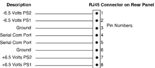
Pinout for RJ45 Connector On Rear Panel
Appendix A: Safety & Compliance
Federal Communications Commission (FCC) Compliance Notices
Class A Interference Statement
This equipment has been tested and found to comply with the limits for a Class A digital device, pursuant to Part 15, Subpart B of the FCC Rules. These limits are designed to provide reasonable protection against harmful interference in a commercial installation. This equipment generates, uses, and can radiate radio frequency energy and, if not installed and used in accordance with the instructions, may cause harmful interference to radio communications. However, there is no guarantee that interference will not occur in a particular installation. Operation of this equipment in a residential area is likely to cause harmful interference in which case the user will be required to correct the interference at his own expense. If this equipment does cause harmful interference to radio or television reception, which can be determined by turning the equipment off and on, the user is encouraged to try to correct the interference by one or more of the following measures:
- Reorient or relocate the receiving antenna.
- Increase the separation between the equipment and receiver.
- Connect the equipment into an outlet on a circuit different from that to which the receiver is connected.
- Consult the dealer or an experienced radio/TV technician for help.
FCC Caution
This device complies with Part 15 of the FCC Rules. Operation is subject to the following two conditions: (1) This device may not cause harmful interference, and (2) this device must accept any interference received, including interference that may cause undesired operation.
Canadian ICES Statement
Canadian Department of Communications Radio Interference Regulations
This digital apparatus does not exceed the Class A limits for radio-noise emissions from a digital apparatus as set out in the Radio Interference Regulations of the Canadian Department of Communications. This Class A digital apparatus complies with Canadian ICES-003.
European Union and European Free Trade Association (EFTA) Regulatory Compliance
This equipment may be operated in the countries that comprise the member countries of the European Union and the European Free Trade Association. These countries, listed in the following paragraph, are referred to as The European Community throughout this document:
AUSTRIA, BELGIUM, BULGARIA, CYPRUS, CZECH REPUBLIC, DENMARK, ESTONIA, FINLAND, FRANCE, GERMANY, GREECE, HUNGARY, IRELAND, ITALY, LATVIA, LITHUANIA, LUXEMBOURG, MALTA, NETHERLANDS, POLAND, PORTUGAL, ROMANIA, SLOVAKIA, SLOVENIA, SPAIN, SWEDEN, UNITED KINGDOM, ICELAND, LICHTENSTEIN, NORWAY, SWITZERLAND
Declaration of Conformity
Marking by this symbol indicates compliance with the Essential Requirements of the EMC Directive of the European Union 2004/108/EC.
CE
This equipment meets the following conformance standards:
Safety:
CB- IEC 60065:2001 + A1:2005
NRTL - UL 60065:2003 R11.06, CSA C22.2 NO. 60065:2003 + A1:06
GS - EN 60065:2002 + A1
Additional licenses issued for specific countries available on request.
Emissions:
EN 55103-1: 1996
EN61000-3-2:2006, EN61000-3-3:1995 +A1:2001 +A2:2005
Immunity:
EN 55103-2: 1996
EN61000-4-2:1995 + A1:1999 + A2:2001, EN61000-4-3:2006, EN61000-4-4:2004,
EN 61000-4-5: 2005, EN 610004-6:2007, EN61000-4-11:2004
The product is also licensed for additional country specific standards as required for the International Marketplace.

Warning!
This is a Class A product. In a domestic environment, this product may cause radio interference, in which case, the user may be required to take appropriate measures.
Korea KCC Compliance Statement
1) Class A ITE
| Class A(Broadcasting and Communication Equipment for Business Use) | Please note that this equipment has obtained EMC registration for business use (Class A), and it is intended to use in other than home area. |
Taiwan Compliance Statement
警告使用者:
This is a Class A product based on the standard of the Bureau of Standards, Metrology and Inspection (BSMI) CNS 13438, Class A.
Japanese Compliance Statement
- Class A ITE
This is a Class A product based on the standard of the VCCI Council (VCCI V-3/2008.04). If this equipment is used in a domestic environment, radio interference may occur, in which case, the user may be required to take corrective actions.
Translated caution statements, warning conventions and warning messages
The following caution statements, warning conventions, and warning messages apply to this product and manual.

Warning Symbol

Hazard Warning

Caution Symbol
Before operating your unit, please read the instructions in this document

Warning!
Read and follow all warning notices and instructions marked on the product or included in the documentation.
Do not use this device near water and clean only with a dry cloth.
Do not block any ventilation openings. Install in accordance with the manufacturer's instructions.
Do not install near any heat sources such as radiators, heat registers, stoves, or other apparatus (including amplifiers) that produce heat.
Refer all servicing to qualified service personnel. Servicing is required when the device has been damaged in any way, such as power-supply cord or plug is damaged, liquid has been spilled or objects have fallen into the device, the device has been exposed to rain or moisture, does not operate normally, or has been
dropped.
This device is a Class A product. Operation of this equipment in a residential area is likely to cause harmful interference, in which case users will be required to take whatever measures may be necessary to correct the interference at their own expense.
Disconnect the external AC power supply line cord(s) from the mains power before moving the unit.
High Voltage. This situation or condition can cause injury due to electric shock.
Only use attachments and accessories specified and/or sold by the manufacturer.
Ensure Mains Power is disconnected before installing the FR1 or FR2 frame R-series modules into the frame, or installing and removing options. If a Mains switch is not provided, the power cord(s) of this equipment provide the means of disconnection. The socket outlet must be installed near the equipment and must be easily
accessible.
FR2 Dual Power Cord Notice—please read this. To reduce the risk of electrical shock, disconnect both power cords before servicing equipment.
Do not defeat the safety purpose of the polarized or grounding-type plug. A polarized plug has two blades with one wider than the other. A grounding type plug has two blades and a third grounding prong. The wide blade or the third prong are provided for your safety. If the provided plug does not fit into your
outlet, consult an electrician for replacement of the obsolete outlet.
Since the Mains plug is used as the disconnection for the device, it must remain readily accessible and operable.
Protect the power cord from being walked on or pinched particularly at plugs, convenience receptacles, and the point where they exit from the device.
Unplug this device during lightning storms or when unused for long periods of time.
The FR1/FR2 front fan door is heavy and is not hinged. Remove with Caution.
- Installation and Operation Guide
- Trademarks
- Notice
- Contacting Support
- Limited Warranty
- Important Safety Information
- Introduction
- Model FR1
- Model FR2
- Features
- FR1 and FR2 Frames
- FR1 Features
- FR2 Features
- I/O Connections
- FR2 Multiple Card Frame, Rear Panel Connectors
- User Controls
- Installation
- Front Door Removal/ Installation
- Caution!
- Power Supply Removal (FR2)
- Warning!
- Specifications
- FR1/FR2 Power Monitoring
- Appendix A: Safety & Compliance
- Federal Communications Commission (FCC) Compliance Notices
- Class A Interference Statement
- FCC Caution
- Canadian ICES Statement
- European Union and European Free Trade Association (EFTA) Regulatory Compliance
- Declaration of Conformity
- CE
- Korea KCC Compliance Statement
- Taiwan Compliance Statement
- Japanese Compliance Statement
- Translated caution statements, warning conventions and warning messages
- Before operating your unit, please read the instructions in this document
Brand : AJA
Model : FR2
Category : NAS