
ST12MHDLNHK - AV Power Strip StarTech.com - Free user manual and instructions
Find the device manual for free ST12MHDLNHK StarTech.com in PDF.


| Product Type | AV Power Strip / Surge Protector |
| Model Number | ST12MHDLNHK |
| Number of Outlets | 12 |
| Input Voltage | 100-240 VAC |
| Maximum Power Rating | 1800W (15A at 120V) |
| Surge Energy Rating | 2400 Joules |
| EMI/RFI Filtering | Yes, >40 dB attenuation |
| Power Cord Length | 6 ft (1.8 m) |
| Form Factor | Horizontal, 1U rack-mountable |
| Mounting Options | Rackmount ears included; also wall-mountable |
| LED Indicators | Power On, Surge Protection Active, Ground Fault |
| Dimensions (W x D x H) | 19 x 8.5 x 1.75 inches (483 x 216 x 44 mm) |
| Weight | 3.5 lbs (1.6 kg) |
| Housing Material | Steel with black powder coat finish |
| Safety Certifications | UL listed, cUL, FCC, CE, RoHS compliant |
| Warranty | Lifetime limited warranty |
| Operating Temperature | 32°F to 104°F (0°C to 40°C) |
| Included Accessories | Mounting brackets, screws, rubber feet, power cord |
Frequently Asked Questions - ST12MHDLNHK StarTech.com
User questions about ST12MHDLNHK StarTech.com
0 question about this device. Answer the ones you know or ask your own.
Ask a new question about this device
Download the instructions for your AV Power Strip in PDF format for free! Find your manual ST12MHDLNHK - StarTech.com and take your electronic device back in hand. On this page are published all the documents necessary for the use of your device. ST12MHDLNHK by StarTech.com.
USER MANUAL ST12MHDLNHK StarTech.com
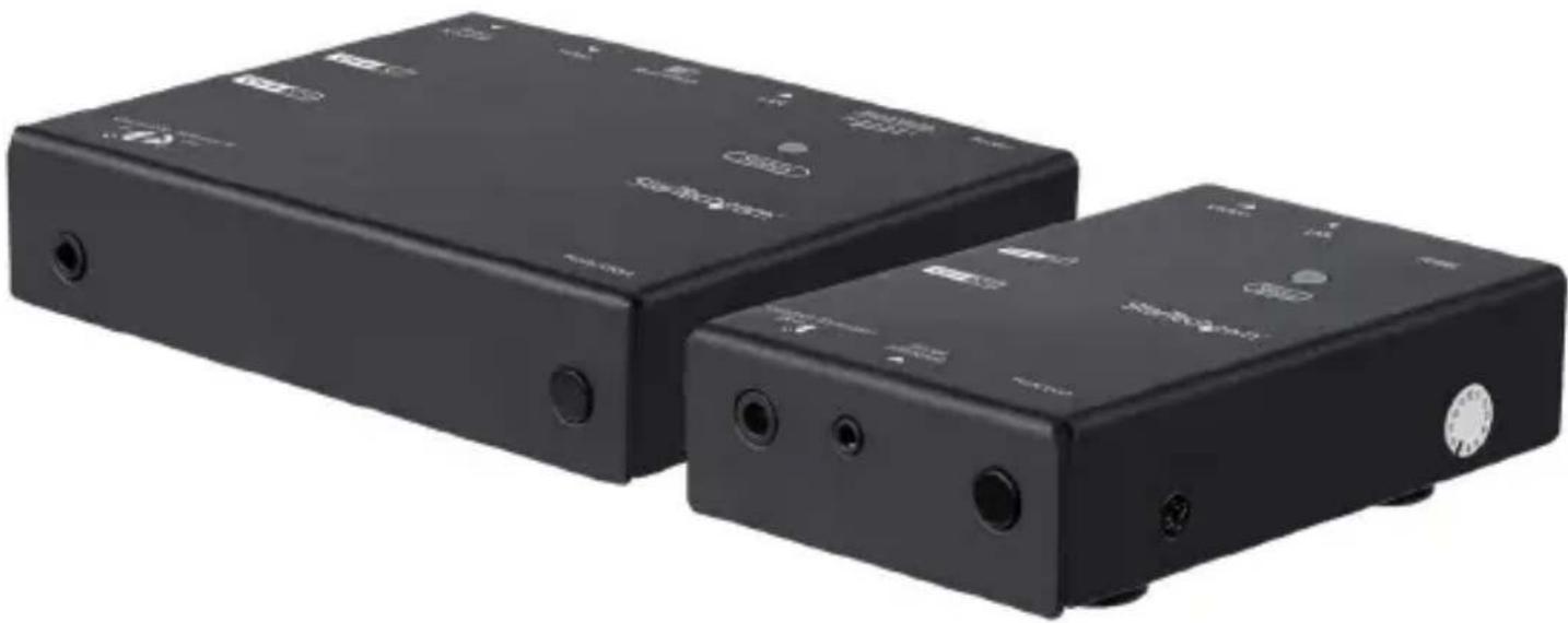
HDMI Over IP Extender Kit - 1080p
ST12MHDLNHK
ST12MHDLNHR
natural_image
Two black electronic devices with labeled ports and connectors, no visible text or symbols on the devices themselves.* actual product may vary from photos
For the latest information, technical specifications, and support for this product, please visit www.startech.com
FCC Compliance Statement
This equipment has been tested and found to comply with the limits for a Class B digital device, pursuant to part 15 of the FCC Rules. These limits are designed to provide reasonable protection against harmful interference in a residential installation. This equipment generates, uses and can radiate radio frequency energy and, if not installed and used in accordance with the instructions, may cause harmful interference to radio communications. However, there is no guarantee that interference will not occur in a particular installation. If this equipment does cause harmful interference to radio or television reception, which can be determined by turning the equipment off and on, the user is encouraged to try to correct the interference by one or more of the following measures:
- Reorient or relocate the receiving antenna.
- Increase the separation between the equipment and receiver.
- Connect the equipment into an outlet on a circuit different from that to which the receiver is connected.
- Consult the dealer or an experienced radio/TV technician for help
This device complies with part 15 of the FCC Rules. Operation is subject to the following two conditions: (1) This device may not cause harmful interference, and (2) this device must accept any interference received, including interference that may cause undesired operation.
Changes or modifications not expressly approved by StarTech.com could void the user's authority to operate the equipment.
Industry Canada Statement
This Class B digital apparatus complies with Canadian ICES-003.
This device complies with Industry Canada licence-exempt RSS standard(s).
Operation is subject to the following two conditions:
(1) This device may not cause interference, and
(2) This device must accept any interference, including interference that may cause undesired operation of the device.
Use of Trademarks, Registered Trademarks, and other Protected Names and Symbols
This manual may make reference to trademarks, registered trademarks, and other protected names and/or symbols of third-party companies not related in any way to StarTech.com. Where they occur these references are for illustrative purposes only and do not represent an endorsement of a product or service by StarTech.com, or an endorsement of the product(s) to which this manual applies by the third-party company in question. Regardless of any direct acknowledgement elsewhere in the body of this document, StarTech.com hereby acknowledges that all trademarks, registered trademarks, service marks, and other protected names and/or symbols contained in this manual and related documents are the property of their respective holders.
Table of Contents
Introduction......1
Package Contents .... 1
Requirements 2
Product Diagram....3
Transmitter Front View 3
Transmitter Rear View....3
Receiver Front View 4
Receiver Rear View....4
Hardware Installation and Configuration ....5
Preparing Your Site 5
Point-to-Point Installation without a LAN Network....5
Point-to-Multipoint Installation with a LAN Network 6
Matrix with a Gigabit LAN Network....7
IP Configuration....8
Operation 10
LED Indicators....10
Push-Button Control 11
Infrared (IR) Blaster and Receiver Operation 11
IR Remote Control....12
Bandwidth Switch....12
Resolution Switch 12
Serial Control 13
Technical support....17
Warranty information....17
Introduction
Package Contents for ST12MHDLNHK
• 1 x HDMI Over IP Transmitter
• 1 x HDMI Over IP Receiver
• 2 x Universal Power Adapters (NA, EU, UK, ANZ)
- 2 x Mounting Brackets
- 2 x CAT5 Cables
- 1 x Plastic Screwdriver
- 1 x IR Remote Control
- 2 x USB-A to Mini USB-B Cable
- 1 x DB9 to 2.5 mm Serial Adapter Cable
- 1 x IR Blaster
- 1 x IR Receiver
- 8 x Rubber Feet
• 1 x Instruction Manual
Package Contents for ST12MHDLNHR
• 1 x HDMI Over IP Receiver
• 1 x Universal Power Adapters (NA, EU, UK, ANZ)
- 1 x Mounting Bracket
- 1 x CAT5 Cable
- 1 x Plastic Screwdriver
- 1 x IR Remote Control
• 1 x USB-A to Mini USB-B Cable
- 1 x DB9 to 2.5 mm Serial Adapter Cable
- 1 x IR Receiver
- 4 x Rubber Feet
• 1 x Instruction Manual
Requirements
- HDMI® Enabled Video Source Device(s) (e.g. computer, Blu-ray™ player)
- HDMI Enabled Display Device(s) (e.g. television, projector) - one for each Receiver
• AC Electrical Outlet for the Transmitter and each Receiver
• HDMI Cable for Video Source(s) and Display(s)
• 10/100 or Gigabit Networking Devices (e.g. LAN hub, router or switch)
• Network Cable (CAT5/5e/6)
Product Diagram
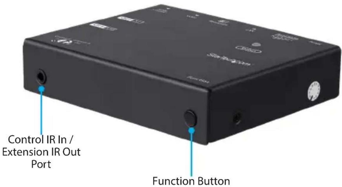
Transmitter Front View
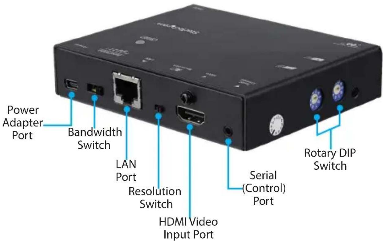
Transmitter Rear View
Receiver Front View

Receiver Rear View

Hardware Installation and Configuration
Preparing Your Site
Note: The ST12MHDLNHK HDMI Over IP Extender Kit can use a 10/100 Ethernet LAN or Gigabit LAN Network (preferred) to extend the signal. Maximum supported distance between two Ethernet devices is 100 meters.
Note: Always use the included Universal Power Adapters.
Ensure the Transmitter and Receiver(s) are all situated near an available AC Electrical Outlet.
- Determine where the HDMI Enabled Video Source (e.g. computer, Blu-ray Player) will be located and set up the device.
- Determine where the HDMI Enabled Display Device will be located and place or mount the display appropriately.
- (Optional) If using additional Receivers (ST12MHDLNHR), determine where the HDMI Enabled Display Device(s) will be located and place or mount the displays appropriately.
Point-to-Point Installation without a LAN Network
1. Install the Transmitter
a) Position the Transmitter near the HDMI Enabled Video Source Device.
b) Connect an HDMI cable from the Source Device (e.g. computer, Blu-ray Player) to the HDMI Video Input Port on the Transmitter.
c) Connect the Transmitter to an AC Electrical Outlet using the Universal Power Adapter.
2. Install the Receiver
a) Position the Receiver near the HDMI Enabled Display Device.
b) Connect an HDMI cable from the video input on the HDMI Enabled Display Device to the HDMI Video Output Port on the Receiver.
c) Connect the Receiver to an AC Electrical Outlet using the Universal Power Adapter.
Note: The Rotary DIP Switch on the Transmitter and Receiver must be set in the same position for the devices to communicate.
3. Connect the Transmitter to the Receiver
a) Connect an RJ-45 terminated CAT5/5e/6 Ethernet cable to the LAN Port on the Transmitter.
Note: If you are using surface cabling, ensure you have enough CAT5/5e/6 unshielded twisted pair (UTP) network cabling to connect the Transmitter to the Receiver's location, and that each end is terminated with an RJ-45 connector.
OR
If you are using premises cabling, ensure that the CAT5/5e/6 unshielded twisted pair (UTP) network cabling between the Transmitter and Receivers has been properly terminated in a wall outlet in each location and there is a patch cable long enough to connect the Transmitter and Receivers to their respective outlets.
b) Connect the other end of the CAT5/5e/6 cable to the RJ-45 connector on the Receiver.
4. Your source video image will now appear on the Receiver's attached video displays.
Point-to-Multipoint Installation with a LAN Network
1. Install the Transmitter
a) Position the Transmitter near the HDMI Enabled Video Source.
b) Connect an HDMI cable from the HDMI Video Input Port on the Transmitter to the video output on the Source Device (e.g. computer, Blu-ray Player).
c) Connect the Transmitter to an AC Electrical Outlet using the Universal Power Adapter.
2. Install the Receivers
a) Position the Receiver(s) near the HDMI Enabled Display Device(s).
b) Connect an HDMI cable from the video input on the HDMI Enabled Display Device to the HDMI Video Output Port on the Receiver.
c) Connect the Receivers to AC Electrical Outlets using the Universal Power Adapters.
Note: The Rotary DIP Switch on the Transmitter and Receivers must be set in the same position for the devices to communicate.
3. Connect the Devices to a LAN Network
Note: If you are using surface cabling, ensure you have enough CAT5/5e/6 unshielded twisted pair (UTP) network cabling to connect the Transmitter to the LAN hub, router, or switch.
OR
If you are using premises cabling, ensure that the CAT5/5e/6 unshielded twisted pair (UTP) network cabling between the Transmitter and LAN hub, router, or
switch has been properly terminated in a wall outlet in each location and there is a patch cable long enough to connect the Transmitter and LAN hub to their respective outlets.
a) Connect an RJ-45 terminated CAT5/5e/6 Ethernet Cable to the LAN Port (RJ-45 Connector) on the Transmitter and Receiver(s).
b) Connect the other end of the CAT5/5e/6 Cable(s), from the Transmitter and Receiver(s), to a LAN hub, router or switch.
Note: Your Router must support IGMP snooping. Refer to your network switch or router documentation to ensure IGMP snooping is supported and enabled.
c) (Optional) When adding additional Receivers (ST12MHDLNHR – sold separately), a run of CAT5/5e/6 Cable will be required from each device to the LAN hub, router or switch.
- Configure your IP address (see "IP Configuration" for detailed instructions).
- Your source video image will now appear on the Video Displays connected to the Receivers.
Matrix with a Gigabit LAN Network
Note: IGMP snooping must be enabled on your Networking Device for matrix/multicast operation.
1. Install the Transmitters
Note: The maximum number of Transmitters you can integrate into your Matrix is 99.
a) Position the Transmitters near the HDMI Enabled Video Sources.
b) Connect HDMI cables from the HDMI Video Input Ports on the Transmitters to the video output ports on the Source Devices (e.g. computer, Blu-ray Player).
c) Connect the Transmitters to AC Electrical Outlets using the Universal Power Adapters.
2. Install the Receivers
a) Position the Receivers near the HDMI Enabled Display Devices.
b) Connect HDMI cables from the HDMI Video Output Ports on the Receivers to the video inputs on the HDMI Enabled Display Devices.
c) Connect the Receivers to AC Electrical Outlets using the Universal Power Adapters.
Note: The Rotary DIP Switch on the connected Transmitters and Receivers must be set in the same position for the devices to communicate.
3. Connect the devices to a Gigabit LAN network
a) Connect an RJ-45 terminated CAT5/5e/6 Ethernet cable to the LAN Port (RJ-45 Connector) on the Transmitters and Receiver(s).
Note: If you are using surface cabling, ensure you have enough CAT5/5e/6 unshielded twisted pair (UTP) network cabling to connect the Transmitter(s) to the LAN hub, router, or switch.
OR
If you are using premises cabling, ensure that the CAT5/5e/6 unshielded twisted pair (UTP) network cabling between the Transmitters and a LAN hub, router, or switch has been properly terminated in a wall outlet in each location and there is a patch cable long enough to connect the Transmitters and LAN hub to their respective outlets.
b) Connect the other end of the CAT5/5e/6 cable run to a LAN hub, router or switch.
Note: Your router must support IGMP snooping. Refer to your network switch or router documentation to ensure IGMP snooping is supported and enabled.
c) (Optional) When connecting additional Receivers (ST12MHDLNHR – sold separately), a run of CAT5/5e/6 cable will be required from each device to the LAN hub, router or switch.
-
Configure your IP address (see "IP Configuration" for detailed instructions).
-
Your source video images will now appear on the Video Displays connected to the Receivers.
IP Configuration
Note: The default IP address of each Transmitter and Receiver will be different.
Determine if DHCP is Supported and Enabled
Discovering whether or not your networking device supports DHCP, and ensuring DHCP is enabled, will determine your next steps when configuring your IP address. If your networking device supports DHCP, and DHCP is enabled, then your hub switch or router will assign an IP address automatically. If your networking device does not support DHCP, or DHCP is not enabled, then your Transmitter and Receiver(s) will default to the factory assigned static IP address.
To check if your computer has DHCP enabled complete the following steps:
Note: Depending on your operating system these instructions may vary.
-
Open your computer's Control Panel.
-
Select View Network Connections.
-
Right-click on the network you intend to connect to and select Properties.
-
Navigate to Internet Protocol Version 4 (TCP/IPv4) and select Properties.
- DHCP is enabled if the following two options are selected: Obtain an IP address automatically and Obtain DNS server address automatically.
- DHCP is not enabled if you have configured your IP manually and the following options are selected: Use the following IP address and Use the following DNS server address.
You can now proceed to configure your IP address automatically or manually, depending upon your DHCP settings.
DHCP is Enabled on your Network Device
If you are using a hub, switch or wireless router that supports DHCP function, enable DHCP. The switch or wireless router will assign the IP address to the Transmitter and Receiver automatically.
Note: The Transmitter(s) and Receiver(s) that are being paired together must be on the same channel to communicate. Ensure the Rotary DIP Switch is set to the same channel on both the Transmitter and Receiver(s).
DHCP is not Enabled on your Network Device
If you are using a hub, switch or wireless router that does not support DHCP, then your Transmitter and Receiver(s) will default to the factory assigned static IP address. To change this IP address you will need to access the Web GUI through your web browser. You must first determine the factory assigned IP address. To do so, you must complete the hardware installation over a network device. By default, each Transmitter and Receiver will have an IP address in the range of 169.254.x.x. Your computer's IP address and Subnet mask must be in the same range to communicate with the Transmitter and Receiver(s) and to become visible on your display. Complete the following steps to configure your computer:
- Open your computer's Control Panel.
- Select View Network Connections.
- Right-click on the network you are going to connect to and select Properties.
- Navigate to Internet Protocol Version 4 (TCP/IPv4) and select Properties.
- Change the IP address to 169.254.x.x (x=number between 0 and 255).
- Change the Subnet mask to 255.255.0.0
When this is complete, and both the Transmitter and the Receiver(s) are powered on, you will see the following information on your computer screen and HDMI Enabled Display Device:
| F/W version: | 0.2.4.0.20160406 |
| RX IP address: | 169.254.4.18 |
| TX IP address: | 169.254.30.117 |
| Group ID: | CH11 |
| Device ID: | IPTV |
| Status: | Connected |
The RX IP address displays the Receiver's IP address. The TX IP address displays the Transmitter's IP address. To access the Transmitter or Receiver for configuration complete the following:
- Enter the TX IP address or RX IP address in the address bar of your web browser.
- Use the default user ID: admin and password: 123456 to log into the GUI.
- Scroll down to the Ethernet header and configure your IP address, Subnet mask, and Gateway to be in the same range for your Transmitter and Receiver(s).
Note: If you have changed your Transmitter and/or Receiver IP settings, configure your computer's IP address, Subnet mask, and Gateway to be in the same range as the new settings for your Transmitter and Receiver in order to access the Web GUI.
Configure the IP Settings for Multiple Transmitters
In order to obtain the IP settings information for multiple Transmitters, configure your Transmitter and Receiver in a one-to-one setup over a LAN. The Rotary DIP Switch on the connected Transmitter and Receiver must be set in the same position or channel for the devices to communicate.
Operation
LED Indicators
| HDMI Over IP Transmitter LED Behavior | Significance |
| Note: For HDCP signals the blue LED is replaced by a purple LED | |
| Flash green Initiating power up | |
| Flash green 1 time + flash blue 2 times Source connected, unlinked | |
| Flash blue 1 time + flash green 2 times LAN connected, unlinked | |
| Flash blue 3 times Source and LAN connected, unlinked | |
Solid green Source connected, linked
Solid blue + flash green 2 times LAN connected, linked
Solid blue + flash blue 2 times Source and LAN connected, linked
HDMI Over IP Receiver LED Behavior Significance
Note: For HDCP signals the Blue LED is replaced by a Purple LED
Flash red Initiating power up
Flash green 3 times Source connected, unlinked
Flash blue 1 time + flash green 2 times LAN and Source connected, unlinked
Solid red Source connected, linked
Solid blue + flash green 2 times LAN connected, linked
Solid blue + flash blue 2 times Source and LAN connected, linked
Solid blue + flash red 2 times EDID copy error
Push-Button Control
Unit Function Button
| HDMI Over IP Transmitter and HDMI Over IP Receiver | Press once to link or unlink the paired Transmitter(s) and Receiver(s) |
| Press and hold for 3 seconds to enter standby mode | |
| Note: Connect your EDID compliant display to the HDMI Video Port on your HDMI Over IP Transmitter and power on the display before attempting this function (Receiver only) Press and hold for 12 seconds for EDID copy function | |
| Press and hold for 24 seconds to restore factory default settings |
Infrared (IR) Blaster and Receiver Operation
Note: IR signals require direct line of sight communication between remote controls and receivers. Ensure your IR Remote Control is pointed directly at your IR Receiver. Also ensure your IR Blaster is pointing directly towards your Source Device's IR receiver. Consult your Source Device's user manual to find the exact location of the IR receiver.
Direct IR Control of the Source Device at the Transmitter
Connect the IR Receiver to the Control IR In / Extension IR Out Port on the Transmitter. Using the IR Remote Control, you can now control the HDMI over IP Transmitter.
Direct IR Control of the Display Device at the Receiver
Connect the IR Receiver to the Control IR In / Extension IR Out Port on the Receiver. Using the IR Remote Control, you can now control the HDMI over IP Receiver.
IR Extension from Receiver to Transmitter
Connect the IR Receiver to the Control IR In / Extension IR Out Port on the Receiver. Connect the IR Blaster to the Control IR In / Extension IR Out Port on the Transmitter. Using the IR Remote Control from your IR Enabled Target Device, situated on the Transmitter side, you can control the IR Device from the Receiver side.
IR Remote Control
| Special Keys Function | |
| M3 (+ Shift to control Transmitter) Channel down | |
| M5 (+ Shift to control Transmitter) Channel up | |
| 1-9 (+ Shift to control Transmitter) Select single digit channel 1~9 | |
| 1-9 +10/0 (+ Shift to control Transmitter) Select double digit channel 10~99 | |
| (Transmitter only) Shift + Video Toggle LAN output on/off | |
| (Receiver only) Video Toggle HDMI output on/off | |
Bandwidth Switch
This four-stage switch enables you to adjust the bandwidth of data that flows through the Transmitter. Toggle the Bandwidth Switch to the high "H" side when using a small number of Transmitters connected to high-definition HDMI Enabled Display Devices. Toggle the Bandwidth Switch to the low "L" side when using a large number of Transmitters connected to high-definition HDMI Enabled Display Devices. Toggle the switch to any of the settings between "H" and "L" to optimize your bandwidth, for optimal display performance when multiple Receivers are attached to one Source Device.
Resolution Switch
This two-stage switch enables you to adjust the resolution of all your HDMI Enabled Display Devices. Toggle the Resolution Switch to the right (the side displaying a small symbol) to enable 1080p resolution. Toggle the switch to the left to enable 720p resolution. Because this switch is located on the Transmitter the resolution will be
adjusted for all of your Display Devices, at all the Receiver sites that have been paired with this Transmitter.
Serial Control
The Transmitter and Receivers can be controlled by direct Serial connection.
Note: Only one Transmitter or Receiver can be controlled at any given time.
To connect either the Transmitter or Receiver(s) to your computer, connect the DB9 to 2.5 mm Serial Adapter Cable to the Serial Port on your computer and the 2.5 mm connector to the Serial (Control) Port on the Transmitter or Receiver. To control the Transmitter or Receiver via Serial, use the following configuration and commands:
Serial Configuration
| Type RS232 | |
| Baud Rate 38400 | |
| Data Bits 8 | |
| Parity None | |
| Stop Bits 1 | |
| Flow Control None |
Transmitter Command Description
| IP=n1.n2.n3.n4 IP Address | Example: n1=192, n2=168, n3=1, n4=1IP Address = 192.168.1.1 |
| NETMASK=n1.n2.n3.n4 Netmask | Example: n1=255, n2=255, n3=255,n4=0Netmask = 255.255.255.0 |
| GATEWAY=n1.n2.n3.n4 Gateway | Example: n1=192, n2=168, n3=1,n4=189Gateway = 192.168.1.189 |
| IPALL=i1.i2.i3.i4n1.n2.n3.n4g1.g2.g3.g4 | Example: i1=192,i2=168, i3=1, i4=1,n1=255, n2=255, n3=255, n4=0, g1=192,g2=168, g3=1, g4=189IP address = 192.168.1.1; Netmask:255.255.255.0; Gateway: 192.168.1.189 |
| GROUP=n Group ID, n: 0 ~ 1023 | Example: n=22, Group ID=22 |
| OBR=n,m Output Bit Rate, n=F, H, S (FHD, HD, SD),m= Bit rate (Kb) | Example: OBR=F, 8, Display in Full HD format with 8 Bit rate |
| DS=n,m Down Scale Output | n = F or H (F = FHD, H = HD), m = F, H, S(F = FHD, H = HD, S = SD ),Example: DS=F, H, Downscale from 1080p to 720pExample: n=115200, Bypass Baud Rate 115200 |
| DN=n Name Device n: ASCII String (max size - 31) | Example: DN = 0C, Device Name = 12 |
| GCID Get company ID | |
| VS View current settings | |
| PI Product information | |
| FACTORY Reset to factory default setting | |
| REBOOT Reboot device | |
| UPDATE Firmware update | |
| PAUSE=n Pause or run the firmware, n: 0 - Run,n=1 - PauseExample: PAUSE=0, Run the firmware | |
| PWD=n Power on / off, n: 0, Power on, n=1,Power offExample: PWD=1, Power off the Transmitter unit | |
| Receiver Command Description | |
| CE Copy monitor EDID to Transmitter | |
| AVOE AV output enable | |
| AVOD AV output disable | |
| MAC=n1 n2 n3 n4 n5 n6 Set MAC address | |
| DHCP=n DHCP On/Off, n : 0 - Off, 1 - OnExample: DHCP = 1, DHCP On | |
| IP=n1.n2.n3.n4 IP address | Example: n1=192, n2=168, n3=1, n4=1IP address=192.168.1.1 |
| NETMASK=n1.n2.n3.n4 Subnet mask | Example: n1=255, n2=255, n3=255,n4=0Subnet mask: 255.255.255.0 |
| GATEWAY=n1.n2.n3.n4 Gateway address | Example: n1=192, n2 =168, n3=1,n4=189Gateway address = 192.168.1.189 |
| IPALL=i1.i2.i3.i4 n1.n2.n3.n4 g1.g2.g3.g4 Example: i1=192,i2=168, i3=1, i4=1n1=255, n2=255, n3=255, n4=0,g1=192 g2=168, g3=1, g4=189,IP address=192.168.1.1; Subnetmask=255.255.255.0;Gateway: 192.168.1.189 | |
| GROUP=n Group ID, n: 0 ~ 1023 | Example: n = 22, Group ID=22 |
| BAUD=n Bypass Baud Rate, | n : 2400, 4800, 9600, 19200, 28800, 38400, 57600, 115200Example: BAUD = 115200, Bypass Baud Rate115200 |
| DN=n Name Device: n: ASCII String (max size - 31)Example: DN = 0C, Device Name = 12 | |
| GCID Get company ID | |
| VS View current settings | |
| PI Product information | |
| FACTORY Reset to factory default settings | |
| REBOOT Reboot device | |
| UPDATE Firmware update | |
| PAUSE=n Pause firmware, n: 0 - Free run, 1 - PauseExample: PAUSE=0, Run the firmware | |
Technical Support
StarTech.com's lifetime technical support is an integral part of our commitment to provide industry-leading solutions. If you ever need help with your product, visit www.startech.com/support and access our comprehensive selection of online tools, documentation, and downloads.
For the latest drivers/software, please visit www.startech.com/downloads
Warranty Information
This product is backed by a two-year warranty.
StarTech.com warrants its products against defects in materials and workmanship for the periods noted, following the initial date of purchase. During this period, the products may be returned for repair, or replacement with equivalent products at our discretion. The warranty covers parts and labor costs only. StarTech.com does not warrant its products from defects or damages arising from misuse, abuse, alteration, or normal wear and tear.
Limitation of Liability
In no event shall the liability of StarTech.com Ltd. and StarTech.com USA LLP (or their officers, directors, employees or agents) for any damages (whether direct or indirect, special, punitive, incidental, consequential, or otherwise), loss of profits, loss of business, or any pecuniary loss, arising out of or related to the use of the product exceed the actual price paid for the product. Some states do not allow the exclusion or limitation of incidental or consequential damages. If such laws apply, the limitations or exclusions contained in this statement may not apply to you.
- HDMI Over IP Extender Kit - 1080p
- FCC Compliance Statement
- Industry Canada Statement
- Use of Trademarks, Registered Trademarks, and other Protected Names and Symbols
- Table of Contents
- Introduction......1
- Product Diagram....3
- Hardware Installation and Configuration ....5
- Operation 10
- Technical support....17
- Warranty information....17
- Introduction
- Package Contents for ST12MHDLNHK
- Package Contents for ST12MHDLNHR
- Requirements
- Product Diagram
- Transmitter Front View
- Transmitter Rear View
- Receiver Front View
- Receiver Rear View
- Hardware Installation and Configuration
- Preparing Your Site
- Point-to-Point Installation without a LAN Network
- Install the Transmitter
- Install the Receiver
- Connect the Transmitter to the Receiver
- OR
- Your source video image will now appear on the Receiver's attached video displays.
- Point-to-Multipoint Installation with a LAN Network
- Install the Receivers
- Connect the Devices to a LAN Network
- Matrix with a Gigabit LAN Network
- Install the Transmitters
- Connect the devices to a Gigabit LAN network
- IP Configuration
- Determine if DHCP is Supported and Enabled
- DHCP is Enabled on your Network Device
- DHCP is not Enabled on your Network Device
- Configure the IP Settings for Multiple Transmitters
- Operation
- LED Indicators
- Infrared (IR) Blaster and Receiver Operation
- Direct IR Control of the Source Device at the Transmitter
- Direct IR Control of the Display Device at the Receiver
- IR Extension from Receiver to Transmitter
- IR Remote Control
- Bandwidth Switch
- Resolution Switch
- Serial Control
- Technical Support
- Warranty Information
- Limitation of Liability
Brand : StarTech.com
Model : ST12MHDLNHK
Category : AV Power Strip